EP0583073A1 - Cordless telephone system - Google Patents
Cordless telephone system Download PDFInfo
- Publication number
- EP0583073A1 EP0583073A1 EP93305502A EP93305502A EP0583073A1 EP 0583073 A1 EP0583073 A1 EP 0583073A1 EP 93305502 A EP93305502 A EP 93305502A EP 93305502 A EP93305502 A EP 93305502A EP 0583073 A1 EP0583073 A1 EP 0583073A1
- Authority
- EP
- European Patent Office
- Prior art keywords
- telephone
- parent
- child
- channels
- channel
- Prior art date
- Legal status (The legal status is an assumption and is not a legal conclusion. Google has not performed a legal analysis and makes no representation as to the accuracy of the status listed.)
- Granted
Links
Images


Classifications
-
- H—ELECTRICITY
- H04—ELECTRIC COMMUNICATION TECHNIQUE
- H04W—WIRELESS COMMUNICATION NETWORKS
- H04W72/00—Local resource management
- H04W72/02—Selection of wireless resources by user or terminal
-
- H—ELECTRICITY
- H04—ELECTRIC COMMUNICATION TECHNIQUE
- H04M—TELEPHONIC COMMUNICATION
- H04M1/00—Substation equipment, e.g. for use by subscribers
- H04M1/72—Mobile telephones; Cordless telephones, i.e. devices for establishing wireless links to base stations without route selection
- H04M1/725—Cordless telephones
- H04M1/72502—Cordless telephones with one base station connected to a single line
- H04M1/72505—Radio link set-up procedures
- H04M1/72511—Searching for available channels
-
- H—ELECTRICITY
- H04—ELECTRIC COMMUNICATION TECHNIQUE
- H04M—TELEPHONIC COMMUNICATION
- H04M1/00—Substation equipment, e.g. for use by subscribers
- H04M1/72—Mobile telephones; Cordless telephones, i.e. devices for establishing wireless links to base stations without route selection
- H04M1/725—Cordless telephones
- H04M1/733—Cordless telephones with a plurality of base stations connected to a plurality of lines
-
- Y—GENERAL TAGGING OF NEW TECHNOLOGICAL DEVELOPMENTS; GENERAL TAGGING OF CROSS-SECTIONAL TECHNOLOGIES SPANNING OVER SEVERAL SECTIONS OF THE IPC; TECHNICAL SUBJECTS COVERED BY FORMER USPC CROSS-REFERENCE ART COLLECTIONS [XRACs] AND DIGESTS
- Y02—TECHNOLOGIES OR APPLICATIONS FOR MITIGATION OR ADAPTATION AGAINST CLIMATE CHANGE
- Y02D—CLIMATE CHANGE MITIGATION TECHNOLOGIES IN INFORMATION AND COMMUNICATION TECHNOLOGIES [ICT], I.E. INFORMATION AND COMMUNICATION TECHNOLOGIES AIMING AT THE REDUCTION OF THEIR OWN ENERGY USE
- Y02D30/00—Reducing energy consumption in communication networks
- Y02D30/70—Reducing energy consumption in communication networks in wireless communication networks
Definitions
- the present invention relates to cordless telephones and a method of operating cordless telephones.
- CT-2 are under investigation as standards for digital cordless telephones.
- the CT-2 system there are provided 40 channels in an 800 MHz band.
- a parent telephone and a child telephone are connected by a channel and the channel is used for transmission and reception by being time shared as the transmission frame T and the reception frame R as shown in FIG. 7.
- All the prepared 40 channels are talking channels with control data transmitted and received as attached data to the speech data. Hence, there exists no independent control channel.
- the parent telephone 21 can manage both an outgoing call and an incoming call through the line wire for any of the child telephones 11 to 1j. Further, if a child telephone 11 is previously registered with a plurality of parent telephones 21 to 2i, the child telephone 11 can send a call to and receive a call from the line wire through any of the parent telephones 21 to 2i.
- the cordless telephone on the CT-2 system individually has a narrower service area than that of the cordless telephone on the general cellular system but is simpler in system structure and economical in terms of the telephone charges. Hence, if it is used within an office block or the like, it can provide means for simple communications covering up the narrowness in service area.
- any appreciable effect cannot be obtained unless the period in the sleep mode is set sufficiently longer as compared with the period in the scan mode. Further, since channels as great in number as 40 are sequentially received in the scan mode, the time required for the scan mode becomes relatively long.
- the cycle of the scan mode plus the sleep mode becomes considerably long. Then, when a request for receiving an incoming call is transmitted from a parent telephone, a long time elapses before the child telephone accepts the request for receiving a call, and therefore this method has little practicability.
- the present invention was made to address the above mentioned difficulties.
- the division is made such that: the first group has the first to tenth channels, the second group has the 11th to 20th channels, the third group has the 21st to 30th channels, and the fourth group has the 31st to 40th channels.
- one parent telephone is assigned one group, or one parent telephone uses one group such that: the first parent telephone 21 is assigned the first group, the second parent telephone 22 is assigned the second group, the third parent telephone 23 is assigned the first group, the fourth parent telephone 24 is assigned the third group,
- the connection between the parent telephone and the child telephone is achieved using a channel belonging to the group assigned to the parent telephone.
- the relationships between parent telephones and child telephones are as shown in FIG. 8.
- a cordless telephone system in which one channel is selected out of 40 channels and the selected channel is used in a time-sharing manner for transmission and reception so that speech data is transmitted and received between a parent telephone 2 and a child telephone 1, comprising the steps of: dividing the 40 channels into 4 groups; assigning one of the groups to the parent telephone 2; connecting the parent telephone 2 and the child telephone 1, when the parent telephone 2 is to be connected with the child telephone 1, using a channel belonging to the group assigned to the parent telephone 2; causing the child telephone 1, while it is on standby, to alternately repeat a mode sequentially receiving a plurality of channels of the group assigned to the parent telephone 2 with which the child telephone 1 is registered and a mode to stop operations for a predetermined period of time; and causing the child telephone 1, when there is transmitted a request for connection from the parent telephone 2 during the course of the repetition, to respond to the request for connection using the channel over which the request
- the parent telephone 2 and the child telephone 1 connect with each other using a channel selected from the channels belonging only to one group as one of the divisions into which 40 channels are divided.
- reference numeral 1 denotes a child telephone
- 2 denotes a parent telephone
- 3 denotes a telephone line (line wire).
- the child telephone 1 represents an arbitrary set chosen out of the child telephones 11 to 1n shown in FIG. 8
- the parent telephone 2 represents an arbitrary set chosen out of the parent telephones 21 to 2m shown in FIG. 8.
- 110 denotes its transmission line and 120 denotes its reception line.
- the transmission line 110 is such that transmits a speech signal St and a control signal (control data) CTRL, which are converted to an FM signal Su during the period of the transmission frame T.
- Reference numeral 111 denotes a telephone transmitter.
- the reception circuit 120 receives an FM signal Sd from the parent telephone 2 during the period of the reception frame R and demodulates therefrom a speech signal Sr and a control signal CTRL.
- the reception circuit 120 also acquires a detection signal RSSI indicating presence or absence of an FM signal Sd transmitted from the parent telephone 2 by detecting for example an intermediate signal.
- Reference numeral 129 denotes a telephone receiver.
- 100 denotes a transmit/receive antenna and 119 denotes an antenna switch circuit for switching connection of the antenna 100 to the transmission circuit 110 and the reception circuit 120 at the beginning of the transmission frame T and the reception frame R, respectively.
- Reference numerals 131a to 131n denote various operator keys such as the dial keys and talk key, 138 denotes a ringer, and 140 denotes a microcomputer for system control.
- the microcomputer 140 while the command signal CTRL transmitted from the transmission circuit 110 is generated, judgment is made as to the command signal CTRL and the detection signal RSSI acquired from the reception circuit 120. Further, permission/prohibition of transmission/reception by the transmission circuit 110 and the reception circuit 120 and channel selection are performed by the microcomputer 140.
- Reference numeral 141 denotes a ROM, in which identification code CPPID for identifying this child telephone 1 from other child telephones and, for example, processing routines 300 and 500 as shown in FIG. 3 to FIG. 6 are stored.
- reference numeral 142 denotes a nonvolatile memory constituted of a RAM backed up by a battery in this example.
- the RAM 142 stores channel data PSM indicative of the channels which the child telephone 1 monitors for reception while it is in its standby state.
- the child telephone 1 is driven by a battery.
- the parent telephone 2 has similar circuits to the circuits 100 to 142 in the child telephone 1. Having the circuits corresponding to the circuits 100 to 142 denoted by reference numerals 200 and up instead of the reference numerals 100 and up, detailed description of the same will be omitted.
- an NCU (network control unit) 239 instead of the telephone transmitter 111 and the telephone receiver 129 of the child telephone 1.
- the NCU 239 is connected with a transmission circuit 210, a reception circuit 220, and the telephone line 3.
- a ringer signal from the line wire is detected and, thereby, an incoming call is detected by the NCU 239 and the detection output is supplied to the microcomputer 240.
- the parent telephone 2 has nothing corresponding to the telephone transmitter 111, the telephone receiver 129, and the ringer 138.
- the ROM 241 stores identification code CFPID for identifying this parent telephone 2 from other parent telephones and, for example, processing routines 400 and 600 as shown in FIG. 3 to FIG. 6.
- This signal Su is supplied to the antenna 100 through the switch circuit 119 so as to be transmitted to the parent telephone 2.
- the control signal CTRL from the microcomputer 140 is supplied to the transmission circuit 110 so as to be transmitted together with the speech signal during the transmission frame T.
- the signal Su is received by the antenna 200, and the signal Su is supplied to the reception circuit 220 through the switch circuit 219 and the original speech signal St and control signal CTRL are extracted from the same.
- the speech signal St is transmitted over the telephone line 3 through the NCU 239 and the control signal CTRL is supplied to the microcomputer 240.
- the speech signal Sr from the line 3 is supplied to the transmission circuit 210 through the NCU 239 so as to be converted to the FM signal Sd being alive during the reception frame R.
- This signal Sd is supplied to the antenna 200 through the switch circuit 219 and transmitted to the child telephone 1.
- a control signal CTRL from the microcomputer 240 is supplied to the reception circuit 210 and transmitted together with the speech signal during the reception frame R.
- the signal Sd is received by the antenna 100 and this signal Sd is supplied to the reception circuit 120 through the switch circuit 119 and the original speech signal Sr and control signal CTRL are extracted therefrom.
- the speech signal Sr is supplied to the telephone receiver 129 and the control signal CTRL is supplied to the microcomputer 140.
- step 401 of the routine 400 for the parent telephone 2 one channel is selected at random out of the first to fortieth channels.
- step 402 it is determined whether or not a transmit signal Su from the child telephone 1 is transmitted over the channel selected in step 401 through checking the signal RSSI. If it is transmitted, it is checked in the following step 403 whether or not a registration key out of the keys 231a to 231n of the parent telephone 2 is depressed. When it is depressed, in the following step 404, the frame is synchronized with the transmitted signal Su.
- the control signal CTRL is extracted from the synchronized signal Su in the following step 405. Then, in the following step 406, it is checked whether or not the identification code CPPID included in the extracted control signal CTRL is the identification code of a child telephone which can be registered with its own telephone. When the identification code is not that of the child telephone which can be registered with its own telephone, the processing of the microcomputer 240 is returned to step 401.
- step 402 the processing is returned to step 401.
- the processing of the microcomputer 240 is advanced to step 409, and in this step 409, the process corresponding to the request for processing is executed and the processing is then returned to step 401.
- steps 401 to 406 are repeated while signal reception for the child telephone 1 is on standby.
- step 406 the identification code CPPID included in the extracted control signal CTRL is the identification code of a child telephone which can be registered with its own telephone
- step 411 setting is made to confirm the child telephone 1 at the other end every one second until the present routine 400 is ended.
- step 412 data indicative of the capability of the parent telephone 2 executing the present routine 400 is transmitted.
- step 413 the parent telephone 2 waits for arrival of data indicative of the capability of the child telephone 1 to which the parent telephone 2 is currently responding.
- routine 300 for the child telephone 1 has corresponding steps 301 to 309 to steps 401 to 409 for the parent telephone 2. These steps 301 to 309 are executed by the microcomputer 140.
- step 302 it is determined whether or not a transmit signal Sd from the parent telephone 2 is transmitted over the channel selected in step 301, and when it is not transmitted, the processing is advanced to step 303. When it is transmitted, the processing is returned to step 301 through a sleep mode in step 307.
- step 303 it is adapted such that, when the registration key of the child telephone 1 is operated simultaneously with or within a predetermined period of the operation of the registration key of the parent telephone 2 in its step 403, the processing is advanced to step 304. Further, in step 306, it is checked whether or not the identification code CFPID included in the extracted control signal CTRL is the identification code of the parent telephone with which its own telephone can be connected.
- step 307 the child telephone 1 is put in a sleep mode for a predetermined period of time, for example 2 seconds.
- step 306 the identification code CFPID is the identification code of the parent telephone with which its own telephone can be connected
- step 311 setting is made to confirm the parent telephone 2 at the other end every one second until the present routine 300 is ended. Then, in the following step 312, the child telephone 1 waits for the data indicative of the capability of the parent telephone 2 transmitted in step 412.
- step 312 When, in step 312, the data transmitted from the parent telephone is received, then in step 313, data indicative of the capability of the child telephone 1 executing the present routine 300 is transmitted.
- this data is received by the parent telephone in step 413.
- it is checked in the following step 414 whether or not the capability of the child telephone 1 from which the data was received is in conformity with the capability of the parent telephone 2 executing the present routine 400. When it is in conformity, the processing is advanced to step 421.
- step 314 for the child telephone 1 it is checked whether or not the capability of the parent telephone 2 received in step 312 (transmitted in step 412) is in conformity with the capability of the child telephone 1 executing the present routine 300. When it is in conformity, the processing is advanced to step 321.
- step 321 a control signal CTRL requesting for registration of its own telephone with the parent telephone 2 is transmitted, which is received in step 421.
- a control signal CTRL as a reply to the request made in step 321 is transmitted, which is received in step 322.
- step 323 an identification code CFPID of the parent telephone 2 with which the registration is requested transmitted in step 424 is received, and in the following step 324, the identification code CFPID is written into the RAM 142.
- the identification code CPPID of the child telephone 1 requesting for registration is written into the RAM 242 in the step 423 following th step 422. Thereafter, in step 424, the completion of the registration with the parent telephone 2 is transmitted.
- step 431 it is checked whether or not a sleep mode is included in the capability of the child telephone 1 received in step 413 (transmitted in step 313). If it is included, in the following step 432, data as to which group of the groups into which the 40 channels are divided is used by the parent telephone 2 is transmitted.
- the selection or change is achieved by having a predetermined key of the keys 231a to 231n operated. Or, when the steps 401 to 406 are repeated many times, a list of used channels is made out and, according to which, a group having the greatest number of empty channels, for example, is selected.
- step 331 On the side of the child telephone 1, it is checked in step 331 whether or not there is included a sleep mode in the capability of the child telephone 1 transmitted in step 313, and when it is included therein, the data indicative of the group transmitted in step 432 is received in the following step 332. Then, in the following step 333, the data of group received in step 332 and the identification code CFPID of the parent telephone 2 are written into the RAM 142. In the following step 334, a control signal CTRL indicative of confirmation is transmitted and then, in step 335, the transmission and reception are cut off and the channel between it and the parent telephone 2 is released.
- step 433 On the side of the parent telephone 2, in step 433 following step 432, the control signal CTRL as the reply transmitted in step 334 is received.
- step 434 the data of group transmitted in step 432 and the identification code CPPID of the child telephone 1 are written into the RAM 242. Then, in step 435, the transmission and reception are cut off and the channel between it and the child telephone 1 is released.
- steps 421 to 434 are skipped over.
- steps 432 to 434 are skipped over. In such case, skipping is made also from step 314 and step 331 as done from step 414 and step 431.
- the child telephone 1 is registered with the parent telephone 2 and at the same time the group of channels being used by the parent telephone 2 is registered in the child telephone 1.
- the left-hand column and the center column of FIG. 9 show an example of registration of the child telephones 11 to 1n with the parent telephones 21 to 2m, in which the child telephone 11 is registered with the parent telephones 21, 22, and 23, the child telephone 12 is registered only with the parent telephone 21, the child telephone 13 is registered with the parent telephones 21 and 23, and so on.
- the groups and channels which the child telephones 11 to 1n can use are as shown in the right-hand column of FIG. 9. For example, while the child telephone 11 is registered with three parent telephones 21, 22, and 23, the child telephone 11 can use 20 channels of 2 groups since the parent telephone 21 and the parent telephone 23 are using the same group.
- step 309 of the processing routine 300 for the microcomputer 140 another process is executed.
- the routine 500 is executed.
- the routine 600 is executed.
- step 501 of the routine 500 the data indicating the group written in the RAM 142 is read.
- step 503 the child telephone 1 is put in a sleep mode for a predetermined period of time, for example 2 seconds.
- the data specifying the k-th channel of the group read in step 501 is supplied to the transmission circuit 110 and the reception circuit 120 so that the transmitting and receiving channel is set to the k-th channel.
- step 505 it is judged whether or not a signal Sd is being received through the channel set up in step 504 by checking the signal RSSI.
- the variable k is incremented in step 506 and then the processing is returned to step 503.
- the child telephone 1 repeats the mode of checking of presence or absence of a signal Sd from the parent telephone 2 in the channels of the group assigned to the parent telephone 2 and the child telephone 1 and the sleep mode until the signal Sd from the parent telephone 2 is received. This is the state of the child telephone 1 being on standby.
- the state of the parent telephone 2 being on standby is similar to that in the conventional cordless telephone, i.e., by monitoring presence or absence of a ringer signal from the wire line, the parent telephone 2 stands by for an incoming call.
- step 604 the data specifying the k-th channel of the group read in step 601 is supplied to the transmission circuit 210 and the reception circuit 220 and the transmitting and receiving channels are set to the k-th channel.
- step 605 it is judged whether or not the channel set in step 604 is being used by checking the signal RSSI.
- the variable k is incremented in step 606 and the processing is returned to step 604.
- step 605 If, in step 605, a channel corresponding to the variable k is not used, the processing advances to step 611.
- the parent telephone when there is an incoming call, selects an empty channel in the group assigned to the parent telephone 2.
- step 611 the parent telephone 2 calls the child telephone 1. This call is detected by the child telephone 1 in its standby state in step 505 and then the processing is advanced to step 511. Then, a predetermined protocol is executed between the child telephone 1 and the parent telephone 2 and they are connected by a line. Thereafter, the party at the other end of the line wire becomes possible to talk with the user of the child telephone 1.
- Outgoing call from the child telephone 1, termination of a call by the child telephone 1, and others are performed in the same manner as in the ordinary cordless telephone or in accordance with the basic protocol in the CT-2 system.
- the channel number can be reconstructed.
- the present invention can also be applied to other systems than the CT-2 system provided that the system has a plurality of channels (four channels or above) and the channels can be divided into a plurality of groups each having two channels or above.
- the child telephone 1 can be put into a sleep mode while it is on standby, the battery for power supply can be suppressed from being consumed.
- the child telephone 1 scans only a portion of a plurality of channels, it becomes possible to make the period of sleep mode sufficiently longer than the period for the scan mode and, hence, a great power saving effect during the period of the sleep mode can be obtained. Further, since the cycle of the scan mode plus the sleep mode can be made shorter, the interval between the instant of sending request for receiving a call from the parent telephone and the instant of responding by the child telephone to the request for receiving an incoming call can accordingly be shortened.
- the parent telephone 2 is only required to control channels of one group and also the child telephone 1 is only required to control a number of channels corresponding to the parent telephone 2 with which the child telephone 1 is registered, such operations as channel selection can be made faster.
Abstract
dividing the plurality of channels into a plurality of groups;
assigning one of the groups to the parent telephone;
connecting, at the time when the parent telephone is to be connected with the child telephone, the parent telephone with the child telephone using a channel belonging to the assigned group;
alternately repeating, while the child telephone is on standby, a mode in which the child telephone sequentially receives the channels assigned to a parent telephone with which the child telephone is registered and a mode in which the child telephone stops its operation for a predetermined period of time; and
causing the child telephone, when the same receives a request for connection from the parent telephone while the repetition is being made to respond to the request for connection using the channel over which the request for connection is transmitted.
Description
- The present invention relates to cordless telephones and a method of operating cordless telephones.
- In the ETSI Committee in Europe, specifications called CT-2 are under investigation as standards for digital cordless telephones.
- In the CT-2 system, there are provided 40 channels in an 800 MHz band. For example, while talking is occurring over the telephone, a parent telephone and a child telephone are connected by a channel and the channel is used for transmission and reception by being time shared as the transmission frame T and the reception frame R as shown in FIG. 7. All the prepared 40 channels are talking channels with control data transmitted and received as attached data to the speech data. Hence, there exists no independent control channel.
- In the CT-2 system, we can use telephones more versatilely than with ordinary cordless telephones by having them previously registered. More specifically, for example as shown in FIG. 8, if a plurality of
child telephones 11 to 1j are previously registered with aparent telephone 21, theparent telephone 21 can manage both an outgoing call and an incoming call through the line wire for any of thechild telephones 11 to 1j. Further, if achild telephone 11 is previously registered with a plurality ofparent telephones 21 to 2i, thechild telephone 11 can send a call to and receive a call from the line wire through any of theparent telephones 21 to 2i. - The cordless telephone on the CT-2 system individually has a narrower service area than that of the cordless telephone on the general cellular system but is simpler in system structure and economical in terms of the telephone charges. Hence, if it is used within an office block or the like, it can provide means for simple communications covering up the narrowness in service area.
- When an outside call comes in to the above described CT-2 system, it is unknown to the child telephone which parent telephone of those, with which the child telephone is registered, will request the child telephone to receive the call and which channel the parent telephone will use. Therefore, the child telephone on standby must repeat sequential receiving of all of the 40 channels to get ready for a request from a parent telephone for receiving an incoming call.
- Then, however, the battery as power supply to the child telephone is greatly consumed and, hence, the usable period of time of a once charged battery becomes considerably short.
- Therefore, a method in which a scan mode to scan all of the channels sequentially only once and a sleep mode (to stop, for a fixed period of time, the operations of all of the circuits except the system controller) are alternately performed is considered. By so doing, the battery can be suppressed from being consumed because even the system controller consumes little power during the period in the sleep mode.
- In such case, however, any appreciable effect cannot be obtained unless the period in the sleep mode is set sufficiently longer as compared with the period in the scan mode. Further, since channels as great in number as 40 are sequentially received in the scan mode, the time required for the scan mode becomes relatively long.
- Thus, in order to effectively suppress the power consumption of the battery, the cycle of the scan mode plus the sleep mode becomes considerably long. Then, when a request for receiving an incoming call is transmitted from a parent telephone, a long time elapses before the child telephone accepts the request for receiving a call, and therefore this method has little practicability.
- Furthermore, since there are usable channels for talking as many as 40, the degree of freedom in selecting a channel becomes high for both the child telephone and the parent telephone. Accordingly, it is difficult, conversely, to select one channel out of them. Hence, a long time is taken for example in receiving an incoming call as described above.
- The present invention was made to address the above mentioned difficulties.
- Various aspects of the invention are set forth in the accompanying claims. Thus, for example, taking the case where there are channels in number as described above as an example, such that the 40 channels are divided for example into four groups, each with 10 channels.
- For example, the division is made such that:
the first group has the first to tenth channels,
the second group has the 11th to 20th channels,
the third group has the 21st to 30th channels, and
the fourth group has the 31st to 40th channels. - Further, it is arranged such that one parent telephone is assigned one group, or one parent telephone uses one group such that:
thefirst parent telephone 21 is assigned the first group,
thesecond parent telephone 22 is assigned the second group,
thethird parent telephone 23 is assigned the first group,
thefourth parent telephone 24 is assigned the third group,
When a parent telephone is connected with a child telephone, the connection between the parent telephone and the child telephone is achieved using a channel belonging to the group assigned to the parent telephone. The relationships between parent telephones and child telephones are as shown in FIG. 8. - When the child telephone is on standby, the child telephone:
- 1. sequentially receives all of a plurality of channels belonging to the group assigned to the parent telephone with which the child telephone is registered (scan mode),
- 2. goes into a power saving mode for a predetermined period of time if there is detected no request for connection from the parent telephone when the operation in
point 1. above is performed, - 3. repeats the operations in
point 1. andpoint 2. above until a request for connection from the parent telephone is detected, and - 4. responds to the request for connection when it is detected, while performing
point 3. above, using the channel over which the request was detected. - More specifically, using reference numerals of parts corresponding to those used in the later described embodiment, there is provided, in a preferred embodiment, a cordless telephone system, in which one channel is selected out of 40 channels and the selected channel is used in a time-sharing manner for transmission and reception so that speech data is transmitted and received between a
parent telephone 2 and achild telephone 1, comprising the steps of:
dividing the 40 channels into 4 groups;
assigning one of the groups to theparent telephone 2;
connecting theparent telephone 2 and thechild telephone 1, when theparent telephone 2 is to be connected with thechild telephone 1, using a channel belonging to the group assigned to theparent telephone 2;
causing thechild telephone 1, while it is on standby, to alternately repeat a mode sequentially receiving a plurality of channels of the group assigned to theparent telephone 2 with which thechild telephone 1 is registered and a mode to stop operations for a predetermined period of time; and
causing thechild telephone 1, when there is transmitted a request for connection from theparent telephone 2 during the course of the repetition, to respond to the request for connection using the channel over which the request has been transmitted. - In short, the
parent telephone 2 and thechild telephone 1 connect with each other using a channel selected from the channels belonging only to one group as one of the divisions into which 40 channels are divided. - An embodiment of the invention will now be described by way of example only, with reference to the accompanying drawings in which:
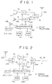
- FIG. 1 is a system diagram showing an example of a child telephone;
- FIG. 2 is a system diagram showing an example of a parent telephone;
- FIG. 3 is a flow chart showing a portion of an example of a registration routine;
- FIG. 4 is a flow chart showing a portion following the portion shown in FIG. 3;
- FIG. 5 is a flow chart showing a portion following the portion shown in FIG. 4;
- FIG. 6 is a flow chart showing an example of an incoming call receiving routine;
- FIG. 7 is a diagram showing a relationship between transmission and reception;
- FIG. 8 is a diagram showing relationships between parent telephones and child telephones; and
- FIG. 9 is a diagram showing an example of relationships between parent telephones, child telephones, and channels.
- Referring to FIG. 1 and FIG. 2,
reference numeral 1 denotes a child telephone, 2 denotes a parent telephone, and 3 denotes a telephone line (line wire). In this case, thechild telephone 1 represents an arbitrary set chosen out of thechild telephones 11 to 1n shown in FIG. 8 and theparent telephone 2 represents an arbitrary set chosen out of theparent telephones 21 to 2m shown in FIG. 8. - In the
child telephone transmission line 110 is such that transmits a speech signal St and a control signal (control data) CTRL, which are converted to an FM signal Su during the period of the transmission frame T. Reference numeral 111 denotes a telephone transmitter. - The
reception circuit 120 receives an FM signal Sd from theparent telephone 2 during the period of the reception frame R and demodulates therefrom a speech signal Sr and a control signal CTRL. Thereception circuit 120 also acquires a detection signal RSSI indicating presence or absence of an FM signal Sd transmitted from theparent telephone 2 by detecting for example an intermediate signal.Reference numeral 129 denotes a telephone receiver. - Further, in the
child telephone antenna 100 to thetransmission circuit 110 and thereception circuit 120 at the beginning of the transmission frame T and the reception frame R, respectively. - Reference numerals 131a to 131n denote various operator keys such as the dial keys and talk key, 138 denotes a ringer, and 140 denotes a microcomputer for system control. In the
microcomputer 140, while the command signal CTRL transmitted from thetransmission circuit 110 is generated, judgment is made as to the command signal CTRL and the detection signal RSSI acquired from thereception circuit 120. Further, permission/prohibition of transmission/reception by thetransmission circuit 110 and thereception circuit 120 and channel selection are performed by themicrocomputer 140. -
Reference numeral 141 denotes a ROM, in which identification code CPPID for identifying thischild telephone 1 from other child telephones and, for example, processingroutines reference numeral 142 denotes a nonvolatile memory constituted of a RAM backed up by a battery in this example. TheRAM 142 stores channel data PSM indicative of the channels which thechild telephone 1 monitors for reception while it is in its standby state. Thechild telephone 1 is driven by a battery. - The
parent telephone 2 has similar circuits to thecircuits 100 to 142 in thechild telephone 1. Having the circuits corresponding to thecircuits 100 to 142 denoted byreference numerals 200 and up instead of thereference numerals 100 and up, detailed description of the same will be omitted. - In the
parent telephone 2, however, there is provided an NCU (network control unit) 239 instead of the telephone transmitter 111 and thetelephone receiver 129 of thechild telephone 1. TheNCU 239 is connected with atransmission circuit 210, areception circuit 220, and thetelephone line 3. A ringer signal from the line wire is detected and, thereby, an incoming call is detected by theNCU 239 and the detection output is supplied to themicrocomputer 240. In the present embodiment, theparent telephone 2 has nothing corresponding to the telephone transmitter 111, thetelephone receiver 129, and theringer 138. - The
ROM 241 stores identification code CFPID for identifying thisparent telephone 2 from other parent telephones and, for example, processingroutines - Between the
child telephone 1 and theparent telephone 2, the following processes are executed and various modes are realized. - The speech signal St from the telephone transmitter 111 1s supplied to the
transmission circuit 110 and converted to the FM signal Su being alive during the transmission frame T. This signal Su is supplied to theantenna 100 through theswitch circuit 119 so as to be transmitted to theparent telephone 2. At this time, the control signal CTRL from themicrocomputer 140 is supplied to thetransmission circuit 110 so as to be transmitted together with the speech signal during the transmission frame T. - In the
parent telephone 2, the signal Su is received by theantenna 200, and the signal Su is supplied to thereception circuit 220 through theswitch circuit 219 and the original speech signal St and control signal CTRL are extracted from the same. The speech signal St is transmitted over thetelephone line 3 through theNCU 239 and the control signal CTRL is supplied to themicrocomputer 240. - On the other hand, the speech signal Sr from the
line 3 is supplied to thetransmission circuit 210 through theNCU 239 so as to be converted to the FM signal Sd being alive during the reception frame R. This signal Sd is supplied to theantenna 200 through theswitch circuit 219 and transmitted to thechild telephone 1. At this time, a control signal CTRL from themicrocomputer 240 is supplied to thereception circuit 210 and transmitted together with the speech signal during the reception frame R. - In the
child telephone 1, the signal Sd is received by theantenna 100 and this signal Sd is supplied to thereception circuit 120 through theswitch circuit 119 and the original speech signal Sr and control signal CTRL are extracted therefrom. The speech signal Sr is supplied to thetelephone receiver 129 and the control signal CTRL is supplied to themicrocomputer 140. - Thus, it is made possible to talk with the other party using the transmitter/
receiver 111, 129. During the talking or before or after the talking, necessary commands and data are transmitted and received between thechild telephone 1 and theparent telephone 2 using the control signal CTRL. - This is the case where an arbitrary child telephone 1j is registered with an arbitrary parent telephone 2i. The registration is achieved by the
microcomputer 140 executing the routine 300 and themicrocomputer 240 executing the routine 400. Through this process, data of the group used by the parent telephone 2i is registered in the registered child telephone 1j. - In
step 401 of the routine 400 for theparent telephone 2, one channel is selected at random out of the first to fortieth channels. In thefollowing step 402, it is determined whether or not a transmit signal Su from thechild telephone 1 is transmitted over the channel selected instep 401 through checking the signal RSSI. If it is transmitted, it is checked in the followingstep 403 whether or not a registration key out of thekeys 231a to 231n of theparent telephone 2 is depressed. When it is depressed, in the followingstep 404, the frame is synchronized with the transmitted signal Su. - When the synchronization for the frame is achieved, the control signal CTRL is extracted from the synchronized signal Su in the following
step 405. Then, in the followingstep 406, it is checked whether or not the identification code CPPID included in the extracted control signal CTRL is the identification code of a child telephone which can be registered with its own telephone. When the identification code is not that of the child telephone which can be registered with its own telephone, the processing of themicrocomputer 240 is returned to step 401. - Also when any signal Su is not transmitted in
step 402, the processing is returned to step 401. Further, if the requested processing is that effected by another key than the registration key instep 403, the processing of themicrocomputer 240 is advanced to step 409, and in thisstep 409, the process corresponding to the request for processing is executed and the processing is then returned to step 401. - Thus, steps 401 to 406 are repeated while signal reception for the
child telephone 1 is on standby. - When, in
step 406, the identification code CPPID included in the extracted control signal CTRL is the identification code of a child telephone which can be registered with its own telephone, then instep 411, setting is made to confirm thechild telephone 1 at the other end every one second until thepresent routine 400 is ended. In thefollowing step 412, data indicative of the capability of theparent telephone 2 executing thepresent routine 400 is transmitted. Then, in the followingstep 413, theparent telephone 2 waits for arrival of data indicative of the capability of thechild telephone 1 to which theparent telephone 2 is currently responding. - On the other hand, the routine 300 for the
child telephone 1 has correspondingsteps 301 to 309 tosteps 401 to 409 for theparent telephone 2. Thesesteps 301 to 309 are executed by themicrocomputer 140. - However, in
step 302, it is determined whether or not a transmit signal Sd from theparent telephone 2 is transmitted over the channel selected instep 301, and when it is not transmitted, the processing is advanced to step 303. When it is transmitted, the processing is returned to step 301 through a sleep mode instep 307. - In
step 303, it is adapted such that, when the registration key of thechild telephone 1 is operated simultaneously with or within a predetermined period of the operation of the registration key of theparent telephone 2 in itsstep 403, the processing is advanced to step 304. Further, instep 306, it is checked whether or not the identification code CFPID included in the extracted control signal CTRL is the identification code of the parent telephone with which its own telephone can be connected. - In
step 307, thechild telephone 1 is put in a sleep mode for a predetermined period of time, for example 2 seconds. - When, in
step 306, the identification code CFPID is the identification code of the parent telephone with which its own telephone can be connected, then, instep 311, setting is made to confirm theparent telephone 2 at the other end every one second until thepresent routine 300 is ended. Then, in the followingstep 312, thechild telephone 1 waits for the data indicative of the capability of theparent telephone 2 transmitted instep 412. - When, in
step 312, the data transmitted from the parent telephone is received, then instep 313, data indicative of the capability of thechild telephone 1 executing thepresent routine 300 is transmitted. - Then, this data is received by the parent telephone in
step 413. After it has been received, it is checked in the followingstep 414 whether or not the capability of thechild telephone 1 from which the data was received is in conformity with the capability of theparent telephone 2 executing thepresent routine 400. When it is in conformity, the processing is advanced to step 421. - In
step 314 for thechild telephone 1, it is checked whether or not the capability of theparent telephone 2 received in step 312 (transmitted in step 412) is in conformity with the capability of thechild telephone 1 executing thepresent routine 300. When it is in conformity, the processing is advanced to step 321. - In
step 321, a control signal CTRL requesting for registration of its own telephone with theparent telephone 2 is transmitted, which is received instep 421. When it has been received, in the followingstep 422, a control signal CTRL as a reply to the request made instep 321 is transmitted, which is received instep 322. When it has been received, in the followingstep 323, an identification code CFPID of theparent telephone 2 with which the registration is requested transmitted instep 424 is received, and in the followingstep 324, the identification code CFPID is written into theRAM 142. - Also on the side of the
parent telephone 2, the identification code CPPID of thechild telephone 1 requesting for registration is written into theRAM 242 in thestep 423 followingth step 422. Thereafter, instep 424, the completion of the registration with theparent telephone 2 is transmitted. - In the
following step 431, it is checked whether or not a sleep mode is included in the capability of thechild telephone 1 received in step 413 (transmitted in step 313). If it is included, in the followingstep 432, data as to which group of the groups into which the 40 channels are divided is used by theparent telephone 2 is transmitted. - Although there are various ways of dividing the 40 channels into groups, here, for simplicity, the way wherein every 10 channels is assigned to one group as described above will be considered.
- When it becomes necessary for the
parent telephone 2 to newly select a group out of the four groups or to change the selected group from one to another, the selection or change is achieved by having a predetermined key of thekeys 231a to 231n operated. Or, when thesteps 401 to 406 are repeated many times, a list of used channels is made out and, according to which, a group having the greatest number of empty channels, for example, is selected. - On the side of the
child telephone 1, it is checked instep 331 whether or not there is included a sleep mode in the capability of thechild telephone 1 transmitted instep 313, and when it is included therein, the data indicative of the group transmitted instep 432 is received in the followingstep 332. Then, in the followingstep 333, the data of group received instep 332 and the identification code CFPID of theparent telephone 2 are written into theRAM 142. In thefollowing step 334, a control signal CTRL indicative of confirmation is transmitted and then, instep 335, the transmission and reception are cut off and the channel between it and theparent telephone 2 is released. - On the side of the
parent telephone 2, instep 433 followingstep 432, the control signal CTRL as the reply transmitted instep 334 is received. In thefollowing step 434, the data of group transmitted instep 432 and the identification code CPPID of thechild telephone 1 are written into theRAM 242. Then, instep 435, the transmission and reception are cut off and the channel between it and thechild telephone 1 is released. - When, as the result of the checking as to whether or not the capability of the
child telephone 1 is in conformity with the capability of theparent telephone 2 instep 414, it is not in conformity, steps 421 to 434 are skipped over. When a sleep mode is not included in the capability of thechild telephone 1 instep 431,steps 432 to 434 are skipped over. In such case, skipping is made also fromstep 314 and step 331 as done fromstep 414 andstep 431. - In the manner as described above, the
child telephone 1 is registered with theparent telephone 2 and at the same time the group of channels being used by theparent telephone 2 is registered in thechild telephone 1. - The left-hand column and the center column of FIG. 9 show an example of registration of the
child telephones 11 to 1n with theparent telephones 21 to 2m, in which thechild telephone 11 is registered with theparent telephones child telephone 12 is registered only with theparent telephone 21, thechild telephone 13 is registered with theparent telephones - If the groups of channels assigned to (used by) the
parent telephones 21 to 2m are as described above, the groups and channels which thechild telephones 11 to 1n can use are as shown in the right-hand column of FIG. 9. For example, while thechild telephone 11 is registered with threeparent telephones child telephone 11 can use 20 channels of 2 groups since theparent telephone 21 and theparent telephone 23 are using the same group. - This is a state where the
child telephone 1 and theparent telephone 2 are in a standby state for an incoming call. This state is brought about by themicrocomputer 140 executing a routine 500. - When the registration key of the
child telephone 1 is not depressed, then instep 309 of theprocessing routine 300 for themicrocomputer 140, another process is executed. As a portion of thestep 309, the routine 500 is executed. Likewise, as a portion of thestep 409, the routine 600 is executed. - On the side of the
child telephone 1, instep 501 of the routine 500, the data indicating the group written in theRAM 142 is read. In thefollowing step 502, k = 1 is set as the variable k specifying the channel in the read group. - Then, in
step 503, thechild telephone 1 is put in a sleep mode for a predetermined period of time, for example 2 seconds. In thefollowing step 504, the data specifying the k-th channel of the group read instep 501 is supplied to thetransmission circuit 110 and thereception circuit 120 so that the transmitting and receiving channel is set to the k-th channel. - In the
following step 505, it is judged whether or not a signal Sd is being received through the channel set up instep 504 by checking the signal RSSI. When it is not received, the variable k is incremented instep 506 and then the processing is returned to step 503. However, when k becomes k = 11 as the result of increment instep 506, it is initialized to k = 1. - Thus, the
child telephone 1 repeats the mode of checking of presence or absence of a signal Sd from theparent telephone 2 in the channels of the group assigned to theparent telephone 2 and thechild telephone 1 and the sleep mode until the signal Sd from theparent telephone 2 is received. This is the state of thechild telephone 1 being on standby. - The state of the
parent telephone 2 being on standby is similar to that in the conventional cordless telephone, i.e., by monitoring presence or absence of a ringer signal from the wire line, theparent telephone 2 stands by for an incoming call. - If a call comes in from the wire line while the
parent telephone 2 and thechild telephone 1 are in their standby states, the ringer signal indicating the incoming call is detected by theNCU 239 and themicrocomputer 240 is notified of the incoming call. Then, the processing of themicrocomputer 240 is shifted to the routine 600. Instep 601 of the routine 600, the data indicating the group written in theRAM 242 is read, and in the followingstep 602, the variable k specifying the channel in the read group is set to k = 1. - In the
following step 604, the data specifying the k-th channel of the group read instep 601 is supplied to thetransmission circuit 210 and thereception circuit 220 and the transmitting and receiving channels are set to the k-th channel. - In the
following step 605, it is judged whether or not the channel set instep 604 is being used by checking the signal RSSI. When it is used, the variable k is incremented instep 606 and the processing is returned to step 604. However, when k becomes k = 11 as a result of increment instep 606, k is initialized to k = 1. - If, in
step 605, a channel corresponding to the variable k is not used, the processing advances to step 611. - Thus, the
parent telephone 2, when there is an incoming call, selects an empty channel in the group assigned to theparent telephone 2. - In
step 611, theparent telephone 2 calls thechild telephone 1. This call is detected by thechild telephone 1 in its standby state instep 505 and then the processing is advanced to step 511. Then, a predetermined protocol is executed between thechild telephone 1 and theparent telephone 2 and they are connected by a line. Thereafter, the party at the other end of the line wire becomes possible to talk with the user of thechild telephone 1. - Outgoing call from the
child telephone 1, termination of a call by thechild telephone 1, and others are performed in the same manner as in the ordinary cordless telephone or in accordance with the basic protocol in the CT-2 system. - Although the case where 40 channels are sequentially divided into the first to fourth groups each having 10 channels was described in the foregoing, each group can be assigned channels (channel numbers) for example in accordance with the following expression:

where
C: the channel number of a channel belonging to the I-th group
S: initial value, any value of S = 1 to 31
I: channel interval, any value of I = 1 to 4
k: variable, any integer of k = 1 to 9
In this case, by arranging such that the values of S and I are transmitted and received when data of the group is transmitted and received insteps 432ad 332 and written into theRAMs - Although an embodiment adapted to the CT-2 system has been described above, the present invention can also be applied to other systems than the CT-2 system provided that the system has a plurality of channels (four channels or above) and the channels can be divided into a plurality of groups each having two channels or above.
- From at least preferred embodiments of the invention the following meritorious effects can be obtained.
- Since the
child telephone 1 can be put into a sleep mode while it is on standby, the battery for power supply can be suppressed from being consumed. - Since, in that case, the
child telephone 1 scans only a portion of a plurality of channels, it becomes possible to make the period of sleep mode sufficiently longer than the period for the scan mode and, hence, a great power saving effect during the period of the sleep mode can be obtained. Further, since the cycle of the scan mode plus the sleep mode can be made shorter, the interval between the instant of sending request for receiving a call from the parent telephone and the instant of responding by the child telephone to the request for receiving an incoming call can accordingly be shortened. - Further, since the
parent telephone 2 is only required to control channels of one group and also thechild telephone 1 is only required to control a number of channels corresponding to theparent telephone 2 with which thechild telephone 1 is registered, such operations as channel selection can be made faster.
Claims (5)
- A cordless telephone system comprising the steps of:
dividing a great number of channels into a plurality of groups each thereof having a plurality of channels;
assigning each of parent telephones to each group; and
causing a child telephone registered with a specific parent telephone to transmit and receive speech data to and from the parent telephone using in a time-sharing manner one channel selected out of the plurality of channels assigned to said parent telephone. - In a cordless telephone system in which it is adapted such that one channel is selected from a plurality of channels and said selected one channel is used by a parent telephone and a child telephone for transmission and reception in a time-sharing manner to transmit and receive speech data therebetween, the improvement comprising the steps of:
dividing said plurality of channels into a plurality of groups;
assigning one of said groups to said parent telephone;
connecting, at the time when said parent telephone is to be connected with said child telephone, said parent telephone with said child telephone using a channel belonging to said assigned group;
alternately repeating, while said child telephone is on standby, a mode in which said child telephone sequentially receives the channels assigned to a parent telephone with which said child telephone is registered and a mode in which the child telephone stops its operation for a predetermined period of time; and
causing said child telephone, when the same receives a request for connection from said parent telephone while said repetition is being made to respond to the request for connection using the channel over which said request for connection is transmitted. - In a cordless telephone system in which it is adapted such that one channel is selected from a plurality of channels and said selected one channel is used by a parent telephone and a child telephone for transmission and reception in a time-sharing manner to transmit and receive speech data therebetween, the improvement comprising the steps of:
dividing said plurality of channels into a plurality of groups;
assigning one of said groups to said parent telephone;
connecting, at the time when said parent telephone is to be connected with said child telephone, said parent telephone with said child telephone using a channel belonging to said assigned group, wherein the group assigned to said parent telephone is changed when the user operates a predetermined key;
alternately repeating, while said child telephone is on standby, a mode in which said child telephone sequentially receives the channels assigned to a parent telephone with which said child telephone is registered and a mode in which the child telephone stops its operation for a predetermined period of time; and
causing said child telephone, when the same receives a request for connection from said parent telephone while said repetition is being made to respond to the request for connection using the channel over which said request for connection is transmitted. - In a cordless telephone system in which it is adapted such that one channel is selected from a plurality of channels and said selected one channel is used by a parent telephone and a child telephone for transmission and reception in a time-sharing manner to transmit and receive speech data therebetween, the improvement comprising the steps of:
dividing said plurality of channels into a plurality of groups;
assigning one of said groups to said parent telephone;
connecting, at the time when said parent telephone is to be connected with said child telephone, said parent telephone with said child telephone using a channel belonging to said assigned group, wherein the group assigned to said parent telephone is changed to a group having a larger number of empty channels when the user operates a predetermined key;
alternately repeating, while said child telephone is on standby, a mode in which said child telephone sequentially receives the channels assigned to a parent telephone with which said child telephone is registered and a mode in which the child telephone stops its operation for a predetermined period of time; and
causing said child telephone, when the same receives a request for connection from said parent telephone while said repetition is being made to respond to the request for connection using the channel over which said request for connection is transmitted. - In a cordless telephone system in which it is adapted such that a plurality of child telephones can be registered with one parent telephone, one child telephone can be registered with a plurality of parent telephones, one channel is selected from a plurality of channels, and said selected one channel is used by said parent telephone and said child telephone for transmission and reception in a time-sharing manner to transmit and receive speech data therebetween, the improvement comprising the steps of:
dividing said plurality of channels into a plurality of groups;
assigning one of said groups to said parent telephone;
connecting, at the time when said parent telephone is to be connected with said child telephone, said parent telephone with said child telephone using a channel belonging to said assigned group;
alternately repeating, while said child telephone is on standby, a mode in which said child telephone sequentially receives the channels assigned to a parent telephone with which said child telephone is registered and a mode in which the child telephone stops its operation for a predetermined period of time; and
causing said child telephone, when the same receives a request for connection from said parent telephone while said repetition is being made, to respond to the request for connection using the channel over which said request for connection is transmitted.
Applications Claiming Priority (2)
| Application Number | Priority Date | Filing Date | Title |
|---|---|---|---|
| JP222178/92 | 1992-07-29 | ||
| JP22217892A JP3166796B2 (en) | 1992-07-29 | 1992-07-29 | Cordless phone |
Publications (2)
| Publication Number | Publication Date |
|---|---|
| EP0583073A1 true EP0583073A1 (en) | 1994-02-16 |
| EP0583073B1 EP0583073B1 (en) | 1998-06-10 |
Family
ID=16778391
Family Applications (1)
| Application Number | Title | Priority Date | Filing Date |
|---|---|---|---|
| EP93305502A Expired - Lifetime EP0583073B1 (en) | 1992-07-29 | 1993-07-14 | Cordless telephone system |
Country Status (4)
| Country | Link |
|---|---|
| US (1) | US5627883A (en) |
| EP (1) | EP0583073B1 (en) |
| JP (1) | JP3166796B2 (en) |
| DE (1) | DE69319034T2 (en) |
Cited By (2)
| Publication number | Priority date | Publication date | Assignee | Title |
|---|---|---|---|---|
| WO1997020435A2 (en) * | 1995-11-28 | 1997-06-05 | International Mobile Satellite Organization | Channel allocation method and apparatus in satellite communication network |
| EP0953845A1 (en) * | 1998-04-23 | 1999-11-03 | Electrowatt Technology Innovation AG | Method by which a central unit selects a secondary unit in a transmission system |
Families Citing this family (7)
| Publication number | Priority date | Publication date | Assignee | Title |
|---|---|---|---|---|
| JPH08149546A (en) * | 1994-11-22 | 1996-06-07 | Sony Corp | Cordless telephone set |
| US5799241A (en) * | 1995-01-27 | 1998-08-25 | Matsushita Electric Industrial Co., Ltd. | Radio apparatus |
| US6073035A (en) * | 1996-08-09 | 2000-06-06 | Oki Telecom, Inc. | System unavailablity power reduction method with early failure and no rotation |
| US7457321B2 (en) * | 2003-07-11 | 2008-11-25 | Nortel Networks Limited | Method for requesting and granting a shorter slot cycle in a wireless network |
| DE102004033414A1 (en) | 2004-07-10 | 2006-02-02 | Robert Bosch Gmbh | Method for operating an internal combustion engine and device for carrying out the method |
| JP6140693B2 (en) | 2012-05-29 | 2017-05-31 | 富士通株式会社 | Wireless communication system, wireless station and base station |
| JP6407147B2 (en) * | 2013-06-07 | 2018-10-17 | 古野電気株式会社 | Wireless communication system and wireless communication method |
Citations (6)
| Publication number | Priority date | Publication date | Assignee | Title |
|---|---|---|---|---|
| US4672657A (en) * | 1985-12-17 | 1987-06-09 | Motorola, Inc. | Multichannel telephone system |
| EP0399611A2 (en) * | 1989-05-26 | 1990-11-28 | Philips Electronics Uk Limited | A communications system for data transmission over a time division duplex frequency channel |
| EP0441372A2 (en) * | 1990-02-08 | 1991-08-14 | Nec Corporation | Method of assigning optimal channel in multi-station radio communications system |
| EP0466139A2 (en) * | 1990-07-12 | 1992-01-15 | Kabushiki Kaisha Toshiba | Mobile radio communication system |
| US5134710A (en) * | 1988-10-17 | 1992-07-28 | Telefonaktiebolaget L M Ericsson | Method of transmitting call information in a short range mobile telephone system and a radio unit for carrying out the method |
| EP0513841A2 (en) * | 1991-05-17 | 1992-11-19 | Nec Corporation | Dynamic channel assignment cordless telecommunication network |
Family Cites Families (15)
| Publication number | Priority date | Publication date | Assignee | Title |
|---|---|---|---|---|
| US3906166A (en) * | 1973-10-17 | 1975-09-16 | Motorola Inc | Radio telephone system |
| JPS5952933A (en) * | 1982-09-20 | 1984-03-27 | Nec Corp | Call channel switching system |
| DE3485534D1 (en) * | 1983-12-22 | 1992-04-09 | Texas Instruments Deutschland | WIRELESS PHONE. |
| US5095531A (en) * | 1987-08-28 | 1992-03-10 | Iwatsu Electric Co., Ltd. | Mobile communication position registering method and system therefor |
| DE3734946A1 (en) * | 1987-10-15 | 1989-05-03 | Siemens Ag | HEARING DEVICE WITH POSSIBILITY TO TELEPHONE |
| JPH0329430A (en) * | 1989-06-26 | 1991-02-07 | Iwatsu Electric Co Ltd | Time divisional communication method for travelling object communication |
| US5090051A (en) * | 1990-02-22 | 1992-02-18 | Motorola, Inc. | Radio communication system and method for connecting an incoming call to a wireless telephone |
| GB2241851A (en) * | 1990-03-09 | 1991-09-11 | Philips Electronic Associated | Optimising transmitter power in a communications system |
| US5418839A (en) * | 1990-04-13 | 1995-05-23 | Phonemate, Inc. | Environmental adaptive mechanism for channel utilization in cordless telephones |
| AU636220B2 (en) * | 1990-04-17 | 1993-04-22 | Nec Corporation | Cordless key telephone system for covering multiple service areas having exclusively assigned control channels |
| US5276908A (en) * | 1990-10-25 | 1994-01-04 | Northern Telecom Limited | Call set-up and spectrum sharing in radio communication on systems with dynamic channel allocation |
| US5212831A (en) * | 1990-11-28 | 1993-05-18 | Bell Communications Research, Inc. | Method and apparatus for autonomous adaptive frequency assignment in TDMA portable radio systems |
| JP2643650B2 (en) * | 1991-05-20 | 1997-08-20 | 日本電気株式会社 | Location information notification method |
| US5210753A (en) * | 1991-10-31 | 1993-05-11 | International Business Machines Corporation | Robust scheduling mechanm for efficient band-width usage in muliticell wireless local networks |
| JP2836405B2 (en) * | 1992-11-04 | 1998-12-14 | 日本電気株式会社 | Mobile communication base station transceiver |
-
1992
- 1992-07-29 JP JP22217892A patent/JP3166796B2/en not_active Expired - Fee Related
-
1993
- 1993-07-14 EP EP93305502A patent/EP0583073B1/en not_active Expired - Lifetime
- 1993-07-14 DE DE69319034T patent/DE69319034T2/en not_active Expired - Fee Related
-
1995
- 1995-04-07 US US08/418,845 patent/US5627883A/en not_active Expired - Fee Related
Patent Citations (6)
| Publication number | Priority date | Publication date | Assignee | Title |
|---|---|---|---|---|
| US4672657A (en) * | 1985-12-17 | 1987-06-09 | Motorola, Inc. | Multichannel telephone system |
| US5134710A (en) * | 1988-10-17 | 1992-07-28 | Telefonaktiebolaget L M Ericsson | Method of transmitting call information in a short range mobile telephone system and a radio unit for carrying out the method |
| EP0399611A2 (en) * | 1989-05-26 | 1990-11-28 | Philips Electronics Uk Limited | A communications system for data transmission over a time division duplex frequency channel |
| EP0441372A2 (en) * | 1990-02-08 | 1991-08-14 | Nec Corporation | Method of assigning optimal channel in multi-station radio communications system |
| EP0466139A2 (en) * | 1990-07-12 | 1992-01-15 | Kabushiki Kaisha Toshiba | Mobile radio communication system |
| EP0513841A2 (en) * | 1991-05-17 | 1992-11-19 | Nec Corporation | Dynamic channel assignment cordless telecommunication network |
Cited By (5)
| Publication number | Priority date | Publication date | Assignee | Title |
|---|---|---|---|---|
| WO1997020435A2 (en) * | 1995-11-28 | 1997-06-05 | International Mobile Satellite Organization | Channel allocation method and apparatus in satellite communication network |
| WO1997020435A3 (en) * | 1995-11-28 | 1997-07-24 | Int Mobile Satellite Org | Channel allocation method and apparatus in satellite communication network |
| EP0953845A1 (en) * | 1998-04-23 | 1999-11-03 | Electrowatt Technology Innovation AG | Method by which a central unit selects a secondary unit in a transmission system |
| WO1999056138A1 (en) * | 1998-04-23 | 1999-11-04 | Siemens Metering Ag | Method for selecting an outstation using a control centre in a transmission system |
| US7236498B1 (en) | 1998-04-23 | 2007-06-26 | Landis+Gry Ag | Method for selecting an outstation using a control center in a transmission system |
Also Published As
| Publication number | Publication date |
|---|---|
| DE69319034D1 (en) | 1998-07-16 |
| JPH0653897A (en) | 1994-02-25 |
| DE69319034T2 (en) | 1998-10-08 |
| JP3166796B2 (en) | 2001-05-14 |
| US5627883A (en) | 1997-05-06 |
| EP0583073B1 (en) | 1998-06-10 |
Similar Documents
| Publication | Publication Date | Title |
|---|---|---|
| US5699409A (en) | Cordless telephone system for providing set-up communications between subsidiary units through a master unit | |
| US4682351A (en) | Cordless Telephone system | |
| KR100243450B1 (en) | Telecommunication method, system, and second station | |
| US6131038A (en) | Method of and apparatus for selecting a channel in a base station by determining the field intensity of radiowaves received | |
| EP0214809B1 (en) | Radio telephone system control apparatus and method | |
| AU636736B2 (en) | Cordless key telephone system capable of quickly answering incoming calls | |
| US5818918A (en) | Personal handy phone system | |
| US4744101A (en) | Cordless telephone system | |
| US4780715A (en) | Communication system capable of interruption talk during data transmission | |
| JP2561013B2 (en) | Mobile wireless communication system and device | |
| EP0583073B1 (en) | Cordless telephone system | |
| EP0563898B1 (en) | Portable radio telephone and method for selecting radio channel of cheap fee | |
| US6169905B1 (en) | Digital cordless telephone apparatus | |
| US5678181A (en) | Mobile radio communication system capable of avoiding an interference due to collision of radio signals and apparatuses used therein | |
| US5369683A (en) | Line control method and system | |
| US5293419A (en) | Simultaneous voice-call system for cordless telephone | |
| US5926766A (en) | Cordless telephone with division of channels into groups of channels | |
| JPH1175238A (en) | Method and device for controlling communication of mca system | |
| JPH0753345Y2 (en) | Wireless telephone | |
| JPS62204631A (en) | Incoming call in absence detection system | |
| JP2567755B2 (en) | Wireless phone call channel setting method | |
| KR100566997B1 (en) | Radio apparatus for terminal and base in DECT system | |
| JP2521125B2 (en) | Wireless telephone system | |
| KR960004811B1 (en) | Channel scanning method | |
| KR950004748B1 (en) | Channel scan method of the private mobile phone |
Legal Events
| Date | Code | Title | Description |
|---|---|---|---|
| PUAI | Public reference made under article 153(3) epc to a published international application that has entered the european phase |
Free format text: ORIGINAL CODE: 0009012 |
|
| AK | Designated contracting states |
Kind code of ref document: A1 Designated state(s): DE FR GB |
|
| 17P | Request for examination filed |
Effective date: 19940712 |
|
| 17Q | First examination report despatched |
Effective date: 19970313 |
|
| GRAG | Despatch of communication of intention to grant |
Free format text: ORIGINAL CODE: EPIDOS AGRA |
|
| GRAG | Despatch of communication of intention to grant |
Free format text: ORIGINAL CODE: EPIDOS AGRA |
|
| GRAH | Despatch of communication of intention to grant a patent |
Free format text: ORIGINAL CODE: EPIDOS IGRA |
|
| GRAH | Despatch of communication of intention to grant a patent |
Free format text: ORIGINAL CODE: EPIDOS IGRA |
|
| GRAA | (expected) grant |
Free format text: ORIGINAL CODE: 0009210 |
|
| AK | Designated contracting states |
Kind code of ref document: B1 Designated state(s): DE FR GB |
|
| REF | Corresponds to: |
Ref document number: 69319034 Country of ref document: DE Date of ref document: 19980716 |
|
| ET | Fr: translation filed | ||
| PLBE | No opposition filed within time limit |
Free format text: ORIGINAL CODE: 0009261 |
|
| STAA | Information on the status of an ep patent application or granted ep patent |
Free format text: STATUS: NO OPPOSITION FILED WITHIN TIME LIMIT |
|
| 26N | No opposition filed | ||
| PGFP | Annual fee paid to national office [announced via postgrant information from national office to epo] |
Ref country code: DE Payment date: 20010709 Year of fee payment: 9 |
|
| PGFP | Annual fee paid to national office [announced via postgrant information from national office to epo] |
Ref country code: FR Payment date: 20010712 Year of fee payment: 9 |
|
| REG | Reference to a national code |
Ref country code: GB Ref legal event code: IF02 |
|
| PG25 | Lapsed in a contracting state [announced via postgrant information from national office to epo] |
Ref country code: DE Free format text: LAPSE BECAUSE OF NON-PAYMENT OF DUE FEES Effective date: 20030201 |
|
| PG25 | Lapsed in a contracting state [announced via postgrant information from national office to epo] |
Ref country code: FR Free format text: LAPSE BECAUSE OF NON-PAYMENT OF DUE FEES Effective date: 20030331 |
|
| REG | Reference to a national code |
Ref country code: FR Ref legal event code: ST |
|
| PGFP | Annual fee paid to national office [announced via postgrant information from national office to epo] |
Ref country code: GB Payment date: 20030709 Year of fee payment: 11 |
|
| PG25 | Lapsed in a contracting state [announced via postgrant information from national office to epo] |
Ref country code: GB Free format text: LAPSE BECAUSE OF NON-PAYMENT OF DUE FEES Effective date: 20040714 |
|
| GBPC | Gb: european patent ceased through non-payment of renewal fee |
Effective date: 20040714 |