EP0583012A1 - Ventricular assist device - Google Patents
Ventricular assist device Download PDFInfo
- Publication number
- EP0583012A1 EP0583012A1 EP93112967A EP93112967A EP0583012A1 EP 0583012 A1 EP0583012 A1 EP 0583012A1 EP 93112967 A EP93112967 A EP 93112967A EP 93112967 A EP93112967 A EP 93112967A EP 0583012 A1 EP0583012 A1 EP 0583012A1
- Authority
- EP
- European Patent Office
- Prior art keywords
- heart
- ventricle
- cardiac
- compression
- assist device
- Prior art date
- Legal status (The legal status is an assumption and is not a legal conclusion. Google has not performed a legal analysis and makes no representation as to the accuracy of the status listed.)
- Granted
Links
Images


Classifications
-
- A—HUMAN NECESSITIES
- A61—MEDICAL OR VETERINARY SCIENCE; HYGIENE
- A61N—ELECTROTHERAPY; MAGNETOTHERAPY; RADIATION THERAPY; ULTRASOUND THERAPY
- A61N1/00—Electrotherapy; Circuits therefor
- A61N1/18—Applying electric currents by contact electrodes
- A61N1/32—Applying electric currents by contact electrodes alternating or intermittent currents
- A61N1/36—Applying electric currents by contact electrodes alternating or intermittent currents for stimulation
- A61N1/362—Heart stimulators
- A61N1/365—Heart stimulators controlled by a physiological parameter, e.g. heart potential
-
- A—HUMAN NECESSITIES
- A61—MEDICAL OR VETERINARY SCIENCE; HYGIENE
- A61M—DEVICES FOR INTRODUCING MEDIA INTO, OR ONTO, THE BODY; DEVICES FOR TRANSDUCING BODY MEDIA OR FOR TAKING MEDIA FROM THE BODY; DEVICES FOR PRODUCING OR ENDING SLEEP OR STUPOR
- A61M60/00—Blood pumps; Devices for mechanical circulatory actuation; Balloon pumps for circulatory assistance
- A61M60/10—Location thereof with respect to the patient's body
- A61M60/122—Implantable pumps or pumping devices, i.e. the blood being pumped inside the patient's body
- A61M60/165—Implantable pumps or pumping devices, i.e. the blood being pumped inside the patient's body implantable in, on, or around the heart
- A61M60/178—Implantable pumps or pumping devices, i.e. the blood being pumped inside the patient's body implantable in, on, or around the heart drawing blood from a ventricle and returning the blood to the arterial system via a cannula external to the ventricle, e.g. left or right ventricular assist devices
-
- A—HUMAN NECESSITIES
- A61—MEDICAL OR VETERINARY SCIENCE; HYGIENE
- A61M—DEVICES FOR INTRODUCING MEDIA INTO, OR ONTO, THE BODY; DEVICES FOR TRANSDUCING BODY MEDIA OR FOR TAKING MEDIA FROM THE BODY; DEVICES FOR PRODUCING OR ENDING SLEEP OR STUPOR
- A61M60/00—Blood pumps; Devices for mechanical circulatory actuation; Balloon pumps for circulatory assistance
- A61M60/20—Type thereof
- A61M60/247—Positive displacement blood pumps
- A61M60/253—Positive displacement blood pumps including a displacement member directly acting on the blood
- A61M60/258—Piston pumps
-
- A—HUMAN NECESSITIES
- A61—MEDICAL OR VETERINARY SCIENCE; HYGIENE
- A61M—DEVICES FOR INTRODUCING MEDIA INTO, OR ONTO, THE BODY; DEVICES FOR TRANSDUCING BODY MEDIA OR FOR TAKING MEDIA FROM THE BODY; DEVICES FOR PRODUCING OR ENDING SLEEP OR STUPOR
- A61M60/00—Blood pumps; Devices for mechanical circulatory actuation; Balloon pumps for circulatory assistance
- A61M60/40—Details relating to driving
- A61M60/403—Details relating to driving for non-positive displacement blood pumps
- A61M60/408—Details relating to driving for non-positive displacement blood pumps the force acting on the blood contacting member being mechanical, e.g. transmitted by a shaft or cable
- A61M60/411—Details relating to driving for non-positive displacement blood pumps the force acting on the blood contacting member being mechanical, e.g. transmitted by a shaft or cable generated by an electromotor
-
- A—HUMAN NECESSITIES
- A61—MEDICAL OR VETERINARY SCIENCE; HYGIENE
- A61M—DEVICES FOR INTRODUCING MEDIA INTO, OR ONTO, THE BODY; DEVICES FOR TRANSDUCING BODY MEDIA OR FOR TAKING MEDIA FROM THE BODY; DEVICES FOR PRODUCING OR ENDING SLEEP OR STUPOR
- A61M60/00—Blood pumps; Devices for mechanical circulatory actuation; Balloon pumps for circulatory assistance
- A61M60/50—Details relating to control
- A61M60/508—Electronic control means, e.g. for feedback regulation
- A61M60/515—Regulation using real-time patient data
-
- A—HUMAN NECESSITIES
- A61—MEDICAL OR VETERINARY SCIENCE; HYGIENE
- A61M—DEVICES FOR INTRODUCING MEDIA INTO, OR ONTO, THE BODY; DEVICES FOR TRANSDUCING BODY MEDIA OR FOR TAKING MEDIA FROM THE BODY; DEVICES FOR PRODUCING OR ENDING SLEEP OR STUPOR
- A61M60/00—Blood pumps; Devices for mechanical circulatory actuation; Balloon pumps for circulatory assistance
- A61M60/50—Details relating to control
- A61M60/508—Electronic control means, e.g. for feedback regulation
- A61M60/538—Regulation using real-time blood pump operational parameter data, e.g. motor current
-
- A—HUMAN NECESSITIES
- A61—MEDICAL OR VETERINARY SCIENCE; HYGIENE
- A61N—ELECTROTHERAPY; MAGNETOTHERAPY; RADIATION THERAPY; ULTRASOUND THERAPY
- A61N1/00—Electrotherapy; Circuits therefor
- A61N1/18—Applying electric currents by contact electrodes
- A61N1/32—Applying electric currents by contact electrodes alternating or intermittent currents
- A61N1/38—Applying electric currents by contact electrodes alternating or intermittent currents for producing shock effects
- A61N1/39—Heart defibrillators
- A61N1/3956—Implantable devices for applying electric shocks to the heart, e.g. for cardioversion
-
- A—HUMAN NECESSITIES
- A61—MEDICAL OR VETERINARY SCIENCE; HYGIENE
- A61M—DEVICES FOR INTRODUCING MEDIA INTO, OR ONTO, THE BODY; DEVICES FOR TRANSDUCING BODY MEDIA OR FOR TAKING MEDIA FROM THE BODY; DEVICES FOR PRODUCING OR ENDING SLEEP OR STUPOR
- A61M2205/00—General characteristics of the apparatus
- A61M2205/33—Controlling, regulating or measuring
- A61M2205/3303—Using a biosensor
-
- A—HUMAN NECESSITIES
- A61—MEDICAL OR VETERINARY SCIENCE; HYGIENE
- A61N—ELECTROTHERAPY; MAGNETOTHERAPY; RADIATION THERAPY; ULTRASOUND THERAPY
- A61N1/00—Electrotherapy; Circuits therefor
- A61N1/18—Applying electric currents by contact electrodes
- A61N1/32—Applying electric currents by contact electrodes alternating or intermittent currents
- A61N1/36—Applying electric currents by contact electrodes alternating or intermittent currents for stimulation
- A61N1/362—Heart stimulators
- A61N1/3627—Heart stimulators for treating a mechanical deficiency of the heart, e.g. congestive heart failure or cardiomyopathy
Definitions
- This Invention relates to a ventricular assist device and a cardiac compression assembly according to claim 1 and claim 4 respectively.
- CHF congestive heart failure
- Another, patient group potentially in need of mechanical heart assistance consists of cardiac surgery patients who otherwise would die from profound refractory heart failure after removal of cardiopulmonary bypass.
- the intra-aortic balloon has been used to assist the circulation mechanically when other therapies have failed to allow weaning from cardiopulmonary bypass.
- cardiogenic shock heart failure
- a third patient group requiring mechanical heart assistance are those tachyarrhythmia patients who are at risk of sudden death due to electrical cardiac dysfunction but who also are at risk from mechanical heart failure.
- a device designed to assist the failing heart should be able to supplement the heart's workload and also compensate for or support weakened portions of the left ventricular wall, including the apex or interventricular septum.
- Such a device might also incorporate pacemaker and implantable cardioverter/defibrillator technology for treating those patients who also suffer from such electrical dysfunctions as bradycardia or tachyarrhythmias.
- ventricular assist devices and artificial hearts have not met these needs.
- Existing devices generally feature blood flow pathways made from nonbiological materials. These materials (e.g., acrylics, Teflon, silicone rubber) often damage blood cells and blood proteins and produce clots, thereby presenting a generic risk of downstream lodgment (thromboembolism) in the circulatory system; attempts to coat plastics with heparin, an anticoagulant, have not been successful on a long-term basis.
- lodgment thromboembolism
- heparin an anticoagulant
- blood clots cause most of the deaths reported after implantation of an artificial heart or assist device.
- blood clots may cause strokes, kidney failure, death (necrosis) of the intestinal wall or peritonitis, or equally severe damage to other organs.
- VADs lack a satisfactory implantable energy source, they must be continuously powered percutaneously. This produces a high risk of infection and generates psychological problems for the patient, who must be constantly tethered to an external power source.
- Some VADs now under development may offer rechargeable implanted batteries coupled with continuous electromagnetic energy transmission through the skin, the external energy source being a series of nickel cadmium batteries placed in a vest or belt.
- Other state-of-the-research-art VADs may allow the patient to remove the vest or belt for a brief period--up to 20-30 minutes, for example.
- greater freedom from external device dependence continues to be constrained because the implantable batteries used in these devices have a limited number of recharge cycles, poor state-of-charge indicators, poor energy density, and poor energy retention, particularly at body temperature.
- Previous attempts to provide ventricular assistance have ranged from artificial hearts (e.g., the Jarvik-7), to devices which directly pump the blood via an artificial pathway inserted through the ventricular wall, to devices which exert pressure on the outside of the heart.
- pressure-exerting devices involve some form of flexible bladder within a support structure such that expansion of the bladder presses on the ventricle and facilitates expulsion of blood. See, for example, U.S. Patents 3,587,567 to Schiff; 3,371,662 to Heid et al.; 4,048,990 to Goetz; and 4,192,293 to Asrican.
- Another structurally related device (U.S. Patent 4,506,658 to Casile) envisions a truncated conical structure of sac-lined rigid panels separated by contractible and expandable sections.
- the support structure encases all or most of the heart and either pushes against or otherwise contacts the right as well as the left ventricle. This complicates ventricular assistance since most cases of heart failure are due to a failure of the left ventricle, not the right.
- the right ventricle which pumps against a pressure that is typically one-fifth of that seen by the left, is generally capable of proper function without assistance. Accordingly, these devices risk preferentially pumping blood from the right ventricle, as a consequence of which blood would accumulate in the lungs and cause pulmonary edema.
- U.S. Patent 4,536,893 to Parravicini envisions using two segmented sacs, selectively fed by a pumping fluid, to compress the ventricles separately.
- Bladder systems have additional shortcomings. These include the possibility of catastrophic bladder fluid leakage, a propensity for damaging the heart surface due to poor fixation and/or rubbing of the bladder against the heart's surface, and the unnatural convex form presented to the heart's surface during systolic bladder expansion.
- Another type of cardiac assist system is designed to compress all or part of the heart by alternately tightening and releasing a circumferential compression band.
- U.S. Patent 4,304,225 to Freeman involves a flexible strap which is fixed to a contoured plastic block and which would pass across the back of the heart.
- a motor assembly would alternately reel in and release the flexible strap, thereby forcing fluid from the subject organ.
- a pressure of between 20 and 70 mm Hg in the volume under the strap would pump blood from the right ventricle but not the left, since 70 mm Hg or more is required for blood to exit the left ventricle into the aorta.
- the bladder-type devices discussed above such a preference could lead to a buildup of blood in the lungs, producing severe pulmonary complications.
- Patent 4,583,523 to Kleinke and Freeman illustrates a heart assist mechanism with some similarities to the present invention.
- Patent 4,583,523 compresses the aorta, not the left ventricle, and it compresses during the diastolic phase of cardiac contraction instead of the systolic phase.
- it has no means to continuously control the depth of stroke.
- This invention relates to an implantable ventricular assist device which includes (1) one or more movable compression mechanisms for engaging the left ventricle of the heart; (2) an operating mechanism for cyclically actuating the movable compression mechanisms and thereby alternately ejecting blood from the ventricle and permitting the ventricle to refill; (3) a sensing means to detect adequacy of left ventricular stroke volume and/or pressure, (4) a control mechanism to assure adequate left ventricular stroke volume by regulating the compressive force of the compression mechanisms, and also to control pacemaker, cardioverter/defibrillator, and recorder subsystems; and (5) an electrical power source.
- compression mechanisms for engaging the sides of the left ventricle may be spaced triaxially.
- a typical configuration would have three compression assemblies placed in the anterior, lateral, and posterior positions with respect to the left ventricle; viewing the left ventricle from the base of the heart and positioning the midpoint of the right ventricle at 270°, typical midpoints for the three compression assemblies would be 190°, 90°, and 350°.
- Each compression mechanism includes a contoured pressure plate and a soft contact pad mounted on the interior plate surface for suturing and/or gluing the compression mechanism to the ventricle.
- An examination of explanted cardiomyopathic hearts suggests that the typical compression assembly surface should be 4-5 cm long and should be tapered (wider at the top, narrower at the bottom), thereby reflecting the shape of the ventricle.
- Each compression mechanism should cover approximately 70° of circumferential arc.
- the contact pad consists of an elastomer, such as silicone rubber, or a thermoplastic material (durometer range 30-50). To avoid edge stress, the thickness of each contact pad is progressively reduced toward its periphery. To further reduce stresses on the myocardium, bearings and axles are used to mount the pressure plates on the compression mechanism's driving arms: if the contracting heart produces a torquing force, the joint will permit the pressure plate, within specified limits, to follow the natural movement of the heart.
- the triaxial compression mechanisms may be supplemented by a fourth, smaller mechanism positioned on the right ventricle.
- a smaller apical pressure plate may be added.
- one or more compression mechanisms may cooperate with a tension band surgically placed through the interventricular muscle wall of the heart; the opposite ends of the tension band would be connected to a rigid support external to the heart, with one or more pressure plates positioned between the block and the heart.
- the tension bands would be rigidly fixed to the compression mechanisms, which, when closed by the operating means, would reduce the circumference of the band opening and thereby squeeze the heart.
- the operating mechanism for cyclically actuating the compression mechanisms, includes a motor for inducing controlled reciprocating motion plus a means for mechanically translating this motion into pressure-plate compression.
- the invention includes a brushless, battery-powered D.C. motor which utilizes an annular energizing coil and magnets to drive a roller screw.
- the roller screw engages a bellows pusher (or a similarly functioning component, such as a rolling diaphragm), which in turn is connected, via fluid-filled elastomeric tubing, with a compression housing that contains a second bellows.
- a bellows pusher or a similarly functioning component, such as a rolling diaphragm
- the fluid coupling transmits pressure to the second bellows, to which is attached a driving wedge that engages the mounted compression mechanisms and thereby aids ventricular compression.
- the fluid coupling permits the cylindrical motor housing to be implanted in a posterior mediastinum position parallel to the descending aorta, while the pumping mechanism housing is positioned in the left chest, adjacent the left ventricle.
- the motor housing and the pumping mechanism housing would form an integral unit, with the nut of the roller screw bonded to the driving wedge.
- linear movement of the roller screw mechanically governs the degree of pressure-plate movement (compression and return) in the compression axis.
- the assembly may be placed in a lubricant-filled sac. At the same time, tethering the assembly to, for example, the ventral surface of the sac would limit the degree of motion.
- the implanted, programmable control mechanism for regulating actuation of the operating mechanism, utilizes input provided in part from device motion sensors, an arterial blood pressure sensor, blood flow sensors, heart rate-sensing (R-wave sensing) electrodes, and/or ECG morphology-sensing electrodes positioned in the heart and/or on the compression mechanisms.
- the associated pacemaker unit, implantable cardioverter/defibrillator and energy storage device, transcutaneous programmer/interrogation unit, and internal biological recorder are of types known to those skilled in the art.
- transcutaneous power supply is also of a type known to those skilled in the art.
- the implanted electrical source is a pack of high-energy rechargeable batteries and a pickup coil disposed in a biocompatible casing capable of subcutaneous placement.
- device circuitry may also produce and conduct pacemaker pulses and/or cardioverting/defibrillating pulses via the abovementioned electrodes.
- a manually operated mechanism may be provided for moving at least one pressure plate to compress the left ventricle in the event of a device malfunction; sensors may be included in the control mechanism for sensing such malfunctions.
- An object of the invention is to provide a new and improved biocompatible ventricular assist device which (1) can be completely and readily implanted in the patient's body, external to the heart and to blood flow pathways; and (2) is relatively simple, light-weight, and compact.
- An additional object of the invention is to provide compression means which minimize trauma of the myocardial surface due to repeated artificial compression.
- An additional object of this ventricular assist device is to maximize the contribution of native left ventricular function, thereby maintaining the myocardium in an exercised state while increasing device efficiency and further lengthening the interval between rechargings.
- Another object of this invention is to provide such a ventricular assist device which also treats electrical dysfunctions (atrial and ventricular, bradycardic and tachyarrhythmic) to facilitate synchronous pumping, thereby assuring an adequate flow of oxygenated blood.
- electrical dysfunctions atrial and ventricular, bradycardic and tachyarrhythmic
- a further object of this invention is to consume a relatively small amount of electrical energy for mechanical operation, thereby permitting the invention to function for a relatively long period of time between transcutaneous rechargings of the implanted power source.
- Another object of the invention is to provide reliable operation over a relatively long time period, such as a minimum of 5-10 years.
- Yet an additional object of the invention is to provide reliable operation over a large number of cycles.
- An object of this invention is also to provide means for transcutaneous programming of operating parameters and transcutaneous interrogation as to prior operations.
- An additional object of the invention is to provide a failsafe mechanism whereby the compression means, in the event of device failure, does not restrict natural movement of the epicardium and whereby the device can be manually operated by the patient user or another individual.
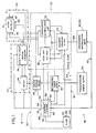
- FIG. 1 discloses a block diagram of one embodiment of a biocompatible ventricular assist and arrhythmia control device 10 in accordance with the invention, hereafter referred to as the ventricular assist device, it being understood that numerous other variations of the invention are, of course, possible.
- the ventricular assist device 10 which operates, on demand, in synchronism with a heart left ventricle 12, comprises an implantable subsystem 14 and a subsystem 16 external to, and without penetrating, a patient user's skin 18.
- the implantable subsystem 14 includes a direct cardiac pumping mechanism 20 and a motor housing 22, both outlined by alternating dashes and asterisks.
- the motor housing 22 includes a motor 24 and a rotary-to-linear motion converter 26 which mechanically initiates (directly or indirectly) the inward ventricle-assist motion of the pumping mechanism 20 when the left ventricle 12 begins to contract, limits and controls the degree of mechanical compression, and terminates the compression stroke so that the pumping mechanism 20 may return to its original outward position as the ventricle refills.
- the pumping mechanism 20 and motor housing 22 also include sensors which provide input to a device control system 28, within an electronic module 30.
- the electronic module 30 further includes a cardiac pacer unit 36 and a cardioverter/defibrillator unit 38 for arrhythmia control, in part to promote operation of the pumping mechanism 20 in synchronism with the left ventricle 12; a biological signal recorder 40; and a patient alarm device 42.
- Another feature of the implantable subsystem 14 is an emergency manual pumping mechanism 44, located outside the electronic module 30 and connected to the direct cardiac pumping mechanism 20.
- the external subsystem 16 includes a power supply 46, for charging the internal power supply 32 transcutaneously, and noninvasive combined programmer/interrogation units 48, 50.
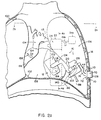
- FIGS 2a and 2b show the ventricular assist device 10, as represented by the block diagram of Figure 1, implanted in an upper portion of a human body 100 for assisting the left ventricle 12 of a heart 102 in the pumping of blood from the heart, through the aorta 104, and to the arterial system. It is to be understood that the disposition of the various parts of the ventricular assist device 10 as shown in Figures 2a, 2b and subsequent figures is merely for purposes of illustration and that other location arrangements may be used.
- the pumping mechanism 20 ( Figure 2a) engages the walls of the left ventricle 12 and is disposed in part between the left ventricle and the left lung 106.
- a manually operable button 108 of the manual pumping mechanism 44 is positioned between two adjacent ribs 110, with the button protruding under the skin 18 to facilitate emergency use by the patient user or by another person.
- the cylindrical motor housing 22 (in outline) of the ventricular assist device 10 is disposed in a posterior mediastinum position parallel to the descending aorta 112.
- the electronic module 30 and rechargeable power supply 32 are combined in a single casing 114 which may be implanted in a subcutaneous abdominal pocket or inside the rib cage, in which case an energy pickup coil 116 of the rechargeable power supply 32 may be positioned subcutaneously between two adjacent ribs 110 ( Figure 2a).
- the pumping mechanism 20 includes triaxial lateral pressure plate assemblies 118 around the heart 102, for engaging and compressing the left ventricle 12 in synchronism with native or pacemaker-initiated pumping action.
- Each pressure plate assembly 118 includes a pressure plate 120 formed of a spring-tempered, biocompatible, inert metal, such as the nickel alloy MP35NR (an alloy of nickel, cobalt, chromium, and molybdenum).
- Each pressure plate 120 is attached to a driver arm 122 or 124 by way of an axle/bearing mount 126 so that the pressure plate may follow, within specified limits, the natural movement of the heart.
- Each driver arm 122 or 124 is mounted on an actuator housing 128, pivoting on a light-weight, high-performance bearing 130, which, like the bearing in the axle/bearing mount 126, consists of a tubular lining of woven Teflon/Dacron fabric and an inner wound fiberglass epoxy resin matrix.
- the driver arms 122 and 124 and the actuator housing 128 consist of a biocompatible metal compound, such as Ti6Al4V (titanium, aluminium, and vanadium).
- Driver arms 122 and 124 are engaged by wedge followers 132, each of which includes a roller 134 mounted on a follower bearing 136 (of similar construction to arm bearing 130).
- the above pumping or compression mechanism 20 is readily adapted to varying combinations of pressure plate assemblies 118.
- triaxial lateral placement could be supplemented with a fourth, smaller plate (not shown) positioned on the right ventricle 138 ( Figure 2a), or with an apical plate (not shown) for supporting and supplying compressive force to the left ventricular apex 140.
- a pumping mechanism 20' includes triaxial lateral pressure plate assemblies 118' (only two shown in Figure 5a) around the heart, with the upper portion of each pressure plate 120' adjoining the left ventricle 12' and the lower portion extending downward into a driver arm 122' or 124' (two of the latter) to which it is fastened by a set screw 200.
- Driver arm 122' differs from driver arms 124' in that its associated pressure plate assembly 118' is shorter, while its upper extension is correspondingly longer to accommodate, wedge follower 132'.
- Driver arm 122 also differs in that its lower extension includes a six-sided rocker plate 202, which extends over housing bearings 204 (one shown) to which each driver arm 124' is also fixed.
- the pressure plates assemblies 118 are movable between solid line, positions when the left ventricle 12 expands (diastole) and broken line positions ( Figures 4b and 4c) when the left ventricle contracts (systole).
- Strain relief sensors may be incorporated on the pressure plates 120 to assure that the pumping mechanism 20 does not restrict filling of the left ventricle 12 and does not assist compression unless natural compression is inadequate.
- each pressure plate assembly 118 also includes a contact pad 142 for gluing and/or suturing the pressure plate assembly to the left ventricle 12.
- the contact pad 142 is bonded to an upper portion of each pressure plate 120 by an adhesive, with both the contact pad and the adhesive consisting of electrically insulating materials, such as a silicone rubber (reinforced with Dacron fibers, in the case of the pad) or a thermoplastic.
- the contact pad 142 has a thickness which is progressively reduced toward its periphery to avoid edge stress, and is soft enough (durometer range 30-50) to minimize the possibility that pressure from the pressure plate assemblies 118 would damage cardiac muscle or the coronary arteries, or would interfere with the muscle's blood supply. (It should be noted that most of the heart muscle's blood supply is delivered during diastole, when minimal force is exerted by the pressure plates 120.)
- Each contact pad 142 includes a rectangular electrode 144 bonded by an electrically insulating adhesive (e.g., a silicone rubber), both to the ventricle-engaging surface of the contact pad 142 and to the pressure plate 120.
- an electrically insulating adhesive e.g., a silicone rubber
- the ventricle-engaging surface of the contact pad 142 contains openings 146, as is best shown in Figure 8.
- Each electrode 144 is connected to the electronic module 30 ( Figures 3a and 3b) via conductors 148 (one shown in Figure 7) that are contained by a cable 150 bonded to one side of the pressure plate 120 and extending downward to the actuator housing 128.
- monitoring and control signals are transmitted to and from the electrodes 144, which may be formed of any suitable material, such as titanium wire mesh.
- a set of bipolar spaced electrodes 152 also is provided on at least one of the pressure plate assemblies 118.
- the electrodes 152 are supported on the pressure plate by an adhesive, such as a silicone rubber, and are connected to respective conductors of the cable 150.
- Another, J-shaped bipolar electrode 154 (Figure 2a) is implanted in or near the right atrium 156 of the heart 102 and is connected to the electronic module 30 ( Figures 3a and 3b) by insulated conductors 158 (only one shown); the connection means may include, for example, a plug 160 that mates with a socket 162 in the electronic module 30.
- the spaced bipolar electrodes 152 and 154 each have an interelectrode spacing of 1-2 centimeters and may be formed of platinum or platinum-iridium.
- contraction of the left ventricle 12 can be properly assisted by compressing the pressure plate assemblies 118 approximately 0.46-0.50 inches (1 centimeter).
- cineangiography studies indicate that the requisite compression distance is relatively independent of heart size, different heart sizes can be accommodated by increasing (or decreasing) the thickness of the contact pads 142 and by selecting larger or smaller plates 120.
- the compression mechanism 20 has been designed such that a one-centimeter stroke can be accomplished within a start-stop range of two centimeters; this permits the position of the pressure plate assemblies 118 to be adjusted to accommodate a range of heart sizes.
- the ventricular assist device 10 is particularly useful if the heart's left ventricle 12 has been damaged by scarring.
- a thin area of scar tissue 164 has formed on the ventricle's ventral wall, replacing contractile muscle. This thinning of the cardiac tissue is a common cause of weakened left ventricular function.
- the scar tissue 164 unable to contract, it may actually bulge outward during systole, absorbing the energy of contraction from the functioning muscle tissue. Accordingly, by positioning the contact pad 142 of a pressure plate assembly 118 over the scar tissue 164, outward bulging of the thin wall during systole is prevented and proper contraction is achieved.
- the motor housing 22 includes a brushless DC motor 24 that drives the pumping mechanism 20 (Figure 4a). It operates directly from rechargeable batteries 166 in the electronic module 30 ( Figures 3a and 3b) and includes an annular energizing coil 24c which surrounds an annular series of permanent magnets (not shown).
- the permanent magnets consist of neodymium, iron, and boron (Nd2Fe14B), or similar materials, for maximum efficiency and reliability as well as minimum weight.
- An energizing field is applied to the permanent magnets in sequence to drive a roller screw device 168 which converts rotary motion to linear motion.
- the roller screw device 168 may, of course, be replaced with a different type of linear actuator (e.g., a ball screw or a set of appropriate gears), if so desired.
- the brushless DC motor 24 may be of a type available on a custom design basis from Sierracin/Magnedyne, of Carlsbad, California. With such a motor, the overall system efficiency (mechanical energy to blood/electrical energy from batteries) is about 60-70% or more, which is significantly higher than the 40-50% efficiency of presently known ventricular assist devices.
- a typical set of design parameters for the motor 24 is as follows: Motor: Rated torque 5 oz-in Rated speed 3/4 radians/sec Input current 1.1 amperes Input voltage 10 volts Input power 13 watts Output power 11 watts Efficiency 85 percent Duty cycle 25-50 percent O.D. 1.25 in I.D. 0.31 in Height 0.87 in Weight 70 grams
- the roller screw device 168 is also of a known type, such as that available from Rollvis S.A. of Geneva, Switzerland. It features a rotatable outer cylinder (nut) 170 that is internally screw threaded, and a reciprocating shaft 172 that is mounted in the cylinder 170 and externally screw threaded. Deep groove ball bearings 174 permit the reciprocating shaft 172 to slide, but not to rotate; this may be accomplished, for example, by interengaging splines and grooves (not shown).
- Another set of ball bearings 176 ( Figures 4d and 4e), situated in a groove in the housing 22, are designed to absorb any torque that would otherwise be exerted on the nut 170.
- the bellows 180 like the motor housing 22, is formed from a suitable biocompatible material, such as Ti6Al4V.
- An elastomeric tube 182 extends from the end of the bellows 180, through the end of the motor housing 22, and connects to a reciprocating bellows 184 that is contained within the actuator housing 128 ( Figure 4a).
- the paired bellows 180, 184 and connecting tube 182 contain a biocompatible fluid, such as mineral oil, and together constitute a fluid coupling.
- Linear motion of the reciprocating shaft 172 causes the nut 170 to exert pressure upon the bellows 180, with the fluid coupling then transmitting pressure to the second bellows 184, to which is welded a driving wedge 186.
- the wedge 186 exerts lateral pressure on the wedge followers 132, which then cause the pressure plate assemblies 118 to pivot on the arm bearings 130 and compress the left ventricle 12 simultaneously.
- the second embodiment of the ventricular assist device 10' ( Figure 5a) is similar to the preferred first embodiment except that an actuator housing 128' and a motor housing 22' are directly joined, with a driving wedge 186' permanently bonded to and surrounding a roller screw nut 170' such that a single wedge follower 132' is directly engaged upon linear movement of a reciprocating shaft 172' (downward in Figure 5a).
- the wedge 186' which is also supported along the distal wall of the housing 22' by bearings 206 (of similar construction to bearings 130', 136', and 204), exerts lateral pressure on the wedge follower 132', which in turn causes a right pressure plate assembly 118' to compress the heart 102'.
- rocker plate 202 is forced downward, exerting pressure on housing bearing 204 and causing the driver arms 124' to pivot on their respective arm bearings 130'.
- all three pressure plate assemblies 118' compress the left ventricle 12' simultaneously.
- the coupling of a motor 24' and the roller screw shaft 172' could be achieved by a magnetic clutch so that in the event of power failure the pressure plate assemblies 118', like those of the preferred embodiment, would present no resisting force to the left ventricle 12'.
- cardiac pumping mechanism 20 or combined pumping mechanism/motor housing 20', 22'
- they may be placed in a lubricant-filled sac (not shown).
- tethering the assembly to the ventral surface of the sac would limit the degree of motion.
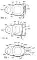
- a ventricular assist device 10'' includes a pressure plate assembly 118'' positioned on a lateral wall of a left ventricle 12'' of a heart 102''.
- an intermediate portion of a titanium or platinum tension band 300 is surgically placed in an interventricular muscle wall 302 between the left ventricle 12'' and a right ventricle 138''.
- Opposite ends of the tension band 300 are fixed to a rigid support (e.g., a curved plate) 304 implanted in adjacent body tissue so as to be essentially immovable.
- a separate defibrillating electrode 306 is mounted on the outside of the right ventricle 138'', for providing cardioverting/defibrillating current to the inner surface of the pressure plate assembly 118''.
- Figure 10 illustrates the action of the ventricular assist device 10'' when the pressure plate assembly 118'' is moved to the left by a pumping mechanism of the type shown in Figures 4a or 5a.
- the pressure plate assembly 118'' and the rigid structure 304 separate, resulting in constriction of the left ventricle 12'' during ventricular contraction.
- the advantage of this embodiment of the invention is that it compensates for weakness of the interventricular muscle wall 302 and, by encompassing the ventricle 12'', gives generalized support to the contracting ventricle.
- a ventricular assist device 10''' includes one or more encircling bands 300' (only one shown) positioned around, for example, a left ventricle 12'''.
- bands 300' are surgically implanted in an interventricular wall 302' between the left ventricle 12''' and a heart right ventricle 138'''.
- opposite ends of the bands 300' are connected to a suitable operating mechanism by being rigidly fixed (e.g., welded) to two pressure plates 120'''.
- an electrical conductor conduit or cable 188 which may be bonded to the actuator housing 128 (as in Figure 4a), includes a multipin connector 190 ( Figure 3) at its free end, which connects with a mating plug 192 that is mounted on the casing 114 of the electronic module 30.
- the conduit 188 houses all electrical conductors (e.g., 148 in Figure 7) running between the cables 150 on the pressure plate assemblies 118 and the electronic module 30.
- an electrical cable 194 connects the electrical motor housing 22 ( Figure 4d) to the electronic module 30 via a second multipin connector 196 and second mating plug 198.
- the electronic module casing 114 houses, in part, one or more electronic circuit packs 52 and the rechargeable power supply 32, the latter including four or more AA batteries 166 and the energy pickup coil 116.
- the electronic circuit packs 52 contain the various units shown in Figure 1, including the control system 28, energy storage device 34, cardiac pacer unit 36, cardioverter/defibrillator 38, biological recorder 40, and alarm device 42.
- the control system 28 may utilitze a variety of sensing strategies to provide optimal mechanical pumping assistance in any of three basic modes: normal left ventricular assist mode, ventricular arrhythmia/asystole mode, and failsafe/standby mode.
- normal assist mode the pressure plate assemblies 118 assist in ventricular compression as needed to maintain sufficient blood flow.
- cardioversion/defibrillation or pacing is attempted, as appropriate. Should cardioverting/defibrillating energy be needed, the pressure plate assemblies 118 would first compress the heart 102 so as to eject blood from the organ and thereby decrease the cardioversion/ defibrillation energy threshold.
- the pumping mechanism 20 responds by compressing the left ventricle 12 at a rate of approximately 72 beats per minute and with sufficient compression depth to maintain systolic pressure of about 90-120 mmHg.
- the pressure plate assemblies 118 in response to failure of the implanted system, would permit natural movement of the heart 102; the manual pumping mechanism 44 could then be used, if needed, by the patient user or a bystander.
- the control system 28 utilizes input from a variety of sensors. For example, data from rate-sensing electrodes 152 ( Figure 7) or 154 ( Figure 2a) enable the control system to coordinate pressure plate compressions with P-waves and to provide A-V synchrony for optimized blood flow, if desired.
- data from rate-sensing electrodes 152 ( Figure 7) or 154 ( Figure 2a) enable the control system to coordinate pressure plate compressions with P-waves and to provide A-V synchrony for optimized blood flow, if desired.
- three Hall-effect sensors (not shown) in the brushless DC motor 24, in combination with the motor's eight magnets, may be used to determine the position of the pressure plate assemblies 118 by sensing rotation of the motor's rotor, which can be translated into linear displacement of the roller screw's reciprocating shaft 172.
- exact displacement of the reciprocating shaft 172 can be determined by integrating the angular velocity of the rotor, which is directly proportional to the back electromotive force (EMF) of the motor 24.
- EMF back electromotive force
- the pressure plate closing velocity and force also can be readily controlled, if desired, by varying the torque of the motor 24 by a servo mechanism 24s (shown schematically in Figures 2a and 4d).
- the control system 28 can calculate and adjust such variables as ejection fraction, aortic blood pressure, stroke volume (cc/beat), and blood flow rate (cc/sec).
- the heart 102 may be allowed to fill to any left ventricular end diastolic volume, depending on left atrial venous return.
- the current of motor 24 can be adjusted to obtain a fixed final ejection position (end systolic volume) in the compression stroke.
- a fixed current can be applied for a given time to the motor 24, which results in a fixed torque and force to the pressure plate assemblies 118. This will result in variable end compression positions, depending, for example, on filling time and volume.
- varying levels of force can be applied to the pressure plate assemblies 118, with sensors then reading the resultant blood pressures and enabling the control system 28 to adjust the force or the end pressure plate position to maintain a programmed aortic blood pressure.
- Aortic root blood pressure may be sensed using a solid-state pressure transducer (not shown) positioned in the aortic wall.
- pressure plate work can be gradually added, as a supplement to natural heart function, until aortic systolic pressure reaches a preprogrammed level. Using servocontrol techniques, the amount of pressure plate assistance will automatically adjust to the level required by the natural heart 102 to maintain the desired aortic pressure. Stroke volume can also be assessed by measuring impedance across the electrodes 144, since impedance is related to blood volume within the heart 102.
- the control system 28 also contains various automatic self-test features. For example; each time the energy storage device 34 supplies energy to the motor 24 for assisting blood circulation or to the cardioverter/defibrillator unit 38 for tachyarrhythmia conversion, the internal voltage of the batteries 166 is compared to a threshold value in a battery test circuit 54 ( Figure 1). If the battery voltage drops below the threshold value, the battery test circuit 54 enables the patient alarm 42, which may utilize a piezoelectric crystal to produce an audio tone. The patient alarm 42 can also be enabled each time a tachyarrhythmia is detected by the control system 28, thereby warning the patient that he is about to receive a defibrillation or cardioversion pulse.
- the control system 28 also includes a real-time electrophysiology/hemodynamic (EH) evaluation mode circuit 56.
- EH electrophysiology/hemodynamic
- the EH mode in which arrhythmia detection by the bipolar electrodes 144 and 152 ( Figure 7) and/or 154 ( Figure 2a) is inhibited, is initiated by command from the programmer 48.
- the cardiac pacer unit 36 then is placed into the VVT mode (i.e., ventricular pacing, ventricular sensing, pulse triggered by sensed event), but with standard electrophysiology equipment providing simulated R-waves to the programmer 48 via a telemetry link.
- the internal recorder 40 also transmits electrocardiogram (ECG) data, ventricular motion data, and blood flow rate data to the programmer 48.
- ECG electrocardiogram
- the cardiac pacer unit 36, cardioverter/defibrillator unit 38, and biological recorder 40, as well as the energy storage device 34, are of types known to those skilled in the art.
- the cardiac pacer unit 36 is noninvasively programmable, has automatic gain control of the input stages, and provides ventricular, atrial, dual chamber, and antitachycardia pacing as required.
- the cardioverter/defibrillator unit 38 is noninvasively programmable, has automatic gain control, and is energized from the energy storage device 34 to provide synchronized defibrillation or cardioversion pulses as required.
- the cardiac pacer 36 and cardioverter/defibrillator 38 in conjunction with the control system 28 and signals from the cardiac electrodes 144 and 152 of the pressure plate pumping assemblies 118 and from the atrial cardiac electrodes 154, typically diagnose tachyarrhythmias using three criteria: rate, morphology, and rate acceleration. (Additional detection parameters can include rate stability and sustained high rate.)
- a rate-detection circuit 58 ( Figure 1) of the control system 28 counts the R-waves as detected by the bipolar electrodes 152, for example, and compares this rate with two or more programmed rate thresholds.
- a morphology-detection circuit 60 examines the shape of transcardiac signals sensed by rectangular electrodes 144 and determines when an absence of isoelectric time occurs, which is characteristic of tachyarrhythmias. Further, an acceleration-detection circuit 62 compares the rate of change of the heart rate with a programmed threshold, rapid acceleration normally being associated with treatable tachyarrhythmias. For example, during exercise-induced sinus tachycardia, rate accelerates typically at 20 beats per minute per second, whereas spontaneous ventricular tachycardia typically results in a rate acceleration of about 90 beats per minute per second.
- Tachyarrhythmias can also be detected by motion sensors because, for example, the ventricle 12 will quiver rather than contract rhythmically during ventricular fibrillation. Combinations of these criteria identify various types of arrhythmic conditions, and for each type an individual treatment sequence can be programmed into the control system 28. Also, in the event of ventricular arrhythmias that cannot be controlled by the arrhythmia-control units 36 and 38, the control system 28 can be programmed to revert to an asynchronous ventricular assist mode to ensure adequate, or at least life-supporting, blood flow.
- Bradycardia diagnosis may be accomplished using signals from the atrial bipolar electrodes 154 ( Figure 2a) and ventricular bipolar electrodes 152 ( Figure 7) on a beat-by-beat basis.
- Other rate-responsive physiological signals may also be used. These signals include venous blood temperature, oxygen content of the blood, blood pH, respiration rate, muscle activity, and QRS duration. If the heart 102 goes into bradycardia and pacing is required, one optional control mode could be to have the pacer 36 search for the optimum pacing rate as determined by measuring cardiac output versus rate.
- Output pulses to the heart 102 from the cardiac pacer unit 36 are typically in the microjoule energy range and are at rates typical of cardiac pacing (60-120 pulses per minute) for bradycardia, or at very high rates (150-1500 pulses per minute) to treat tachyarrhythmias.
- Output pulses from the cardioverter/defibrillator unit 38 are typically in the range of 0.1 joules to 50 joules, and are either asynchronous or synchronous with the R-wave.
- the control system 28 would ensure full compression of the pressure plate assemblies 118 before countershock delivery, thereby minimizing the volume of blood in the heart and achieving a lower cardioversion/defibrillation energy threshold.
- the internal biological recorder 40 records and stores electrogram events, such as tachyarrhythmia onset and conversion; device status, such as battery condition; ventricular motion; and blood flow rate.
- the recorder 40 may utilize a delta-modulation scheme to achieve analog-to-digital conversions of the signals at a typical bit/second rate of 200.
- the delta-modulated data can then be stored, for example, in a CMOS RAM.
- the recorder 40 On command of the programmer unit 48, the recorder 40 then can delta-demodulate the stored data to produce an analog voltage which can be transmitted to the interrogation unit 50 by way of a telemetry link 64.
- the recorder 40 can telemeter on-line data as well as stored data, if desired.
- the batteries 166 of the internal rechargeable power supply 32 may be four or five lithium/molybdenum/disulfide rechargeable "AA" cells (in series), such as those available from Moli Energy Limited of Vancouver, British Columbia, Canada.
- the typical characteristics of each battery 166 are as follows: Ampere-hour capacity 0.7 A Average voltage 2.0V Watt-hour capacity 1.4 W Weight 20 grams Volume 8 cc.
- Some of the important advantages of the batteries 166 over nickel cadmium batteries normally used in ventricular assist devices include an increased energy density (by a factor of about 2.5); weight reduction from 200 grams to 80-100 grams: lower internal impedance, resulting in less power loss; higher voltage per cell; an increase in energy retention by a factor of about four (10% per month versus 40% per month at body temperature), which significantly enhances system efficiency; and a reliable state-of-remaining-capacity indicator (cell voltage), whereas there is no indicator for nickel cadmium cells.
- the depth of cell discharge is accurately controlled by allowing the cell voltage to vary between two predetermined voltage limits, which in turn allows thousands of charge/discharge cycles to be achieved. This is achieved by monitoring battery voltage continuously from the control system 28, automatically activating a charging circuit (not shown) of the rechargeable power supply 32 when a preset lower voltage is reached, and automatically deactivating the charging circuit when battery voltage reaches a preset upper limit.
- a closely coupled magnetic circuit comprising a movable magnet in a coil of wire can be integrated into the driver arms 122 and 124.
- This magnetic circuit would convert into electrical energy some of the mechanical work done as the pressure plate pumping assemblies 118 are expanded during the filling phase of the ventricle 12. The electrical energy would then be supplied to the implanted rechargeable batteries 166. Further, power lost through truncation of cardioversion/defibrillation pulses, which is required for effective ventricular tachyarrhythmia conversion, can be returned to the rechargeable batteries 166 using power MOSFETS instead of SCRs in the output circuits of the cardioverter/defibrillator unit 38.
- the highly efficient batteries 166 combined with the high efficiency of the ventricular assist device 10, permit the internal power supply 32 to operate the implanted device at nominal blood flows for hours before requiring recharging. Further, because the batteries 166 do not off-gas, they can be hermetically sealed within the electronic module's titanium case 114 for enhanced long-term reliability. Thus, the patient's vest- or tether-free time is significantly increased, with a corresponding increase in quality of life.
- the external transcutaneous power supply 46 comprises about 15 power cells (not shown), such as the batteries 166, in a "C" configuration connected in series.
- the external power supply 46 which weighs about two pounds and is worn by the patient in a belt or vest (not shown), keeps the internal power supply 32 fully charged while providing power for the internal subsystem 14 for at least 10 hours without recharging.
- the transcutaneous power supply 46 can operate the internal subsystem 14 up to a day before being recharged or replaced with a fully charged new power supply belt or vest.
- Transcutaneous energy transmission from the external power supply 46 to the internal power supply 32 is accomplished by two inductively coupled concentric coils, one of which is a primary coil (not shown) in the external power supply, and the other of which is the pickup coil 116.
- the latter, secondary coil may be hermetically sealed within the electronic module case 114 (as outlined in Figures 3a and 3b) or may be implanted separately, protected by a butyl rubber coating which is then encapsulated in a polyether-based elastomeric urethane.
- Energy transmission to the secondary coil 116 can typically be performed at 150 KHz. Because of the large surface area for transcutaneous power transmission, the resulting electromagnetic radiation to the patient's tissue is low -- in the range of the earth's magnetic field.
- a telemetry link 66 permits noninvasive programming and interrogation of the internal subsystem 14, with communication from the programmer 48 to an internal device 68 in the control system 28 being accomplished with a digital radio frequency (RF) technique.
- RF radio frequency
- Communication from the internal device 68 to the programmer 48 can be by either an RF channel or an audio channel, the latter using a piezoelectric speaker (not shown). Communication on either channel can be digital for data transmission, or analog for transmission of real-time or recorded electrocardiograms, for example.
- the manual pumping mechanism 44 may be employed to maintain blood flow.
- the mechanism 44 includes, in addition to the push button 108, a cylindrical housing 70 and an annular flange 72 for maintaining the position of the housing.
- the annular flange 72 is connected to the elastomeric tube 182 (Figure 2b) of the fluid coupling between the paired bellows 180 ( Figure 4d) and 184 ( Figures 4a, b and c) by a similar flexible plastic tube 74.
- the push button 108 may be biased outward by, for example, a coil spring (not shown).
- the ventricular assist devices 10-10''' in accordance with the invention are considered advantageous in that each normally should be capable of supporting full cardiac output, if necessary.
- Each device 10-10''' is capable, for example, of supporting a failed left ventricle 12-12''' with a continuous output of 7-10 liters per minute without having to exceed a pump rate of 120 beats per minute into a mean arterial pressure of 120 mmHg (which might be associated, typically, with a peak arterial pressure of 150 mmHg,) and a maximum filling pressure of about 15 mmHg.
- the rate of pressure rise and fall due to pumping assistance will be low enough to avoid excessive blood turbulence, hemolysis, or blood cavitation.
- the pressure plate assemblies 118-118''' or resilient bands 300-300' which are external to the ventricular cavities of the heart 102-102''', do not impede venous return, compromise any organ system, or degrade blood circulation in the coronary arteries.
- the devices 10-10''' also eliminate the need, present in certain prior known ventricular assist devices, for a separate compliance chamber (displaced volume compensation for cycle changes in volume between pumping sacs and encapsulating shells), which may be compromised by fibrous tissue encapsulation and which requires periodic replacement of gas which has diffused through the compliance chamber materials.
- the invention also eliminates the need for any valves, which have inherent and well-documented problems in prior known cardiac assist devices.
- Each of the ventricular assist devices 10-10''' is also advantageous in that it reduces the total weight of all implanted components, when compared to the total weight of known prior art ventricular assist devices.
- the overall weight of the components, including batteries 166, is in a range of 400-500 grams, which represents a weight reduction by a factor of four from known prior art systems that generally weigh 1500-2000 grams.
- ventricular assist device 10 Another advantage of ventricular assist device 10 is that the fluid coupling between the bellows 180 and 184 constitutes a failsafe mechanism whereby the pumping mechanism 20, in the event of motor failure, does not restrict the natural movement of the heart 102. Additionally, several embodiments of the invention would permit separate implantation of the motor housing 22, with only the pumping mechanism 20 implanted adjacent the heart. Furthermore, for all ventricular assist devices 10-10''', the electronic module 30 need not be implanted near the pumping mechanism 20-20', but may be remotely implanted. This modular construction facilitates replacement of components, should any fail, and also allows flexibility in determining the optimum implant sites for the individual patient's physiology.
- device 10 can be completely and readily implanted in the body of a patient user, eliminating the need for tethering to an external power supply; is of relatively simple, light-weight, and compact construction; requires only a small amount of energy for reliable operation over an extended period of time; incorporates a control mechanism for determining left ventricular stroke volume and for changing compressive force, as needed, to assure an adequate supply of oxygenated blood; and includes bradycardic and tachyarrhythmic control features, which will facilitate device operation in synchronism with left ventricular contraction.
- the rechargeable power supply 32 of the device 10 can be readily recharged transcutaneously, and the device can be noninvasively programmed and interrogated.
- the device 10 places no foreign, nonbiological materials in contact with the blood flow, thereby avoiding the documented danger of clotting and associated body malfunctions.
- the device 10 also is capable of providing effective mechanical circulatory support to the ventricle 12 of the heart 102 while myocardial function recovers postoperatively.
Abstract
Description
- This Invention relates to a ventricular assist device and a cardiac compression assembly according to
claim 1 and claim 4 respectively. - The need for an improved ventricular assist device has long been apparent. The pool of patients suffering from congestive heart failure (CHF), a progressive disease often precipitated by acute myocardial infarction, continues to grow. In 1983 alone the estimated incidence of CHF, in the course of which the heart's mechanical pumping action is severely compromised, was 400,000 in the United States. Some 2.3 million or more persons suffer from varying degrees of the disease, with the estimated annual death rate from mechanical cardiac dysfunction being 165,000. Individuals with worsening CHF who otherwise would be expected to have years of productive life ahead of them, are generally regarded as candidates for a ventricular assist system. At present, however, no generally recognized safe and effective assist device is available.
- Another, patient group potentially in need of mechanical heart assistance consists of cardiac surgery patients who otherwise would die from profound refractory heart failure after removal of cardiopulmonary bypass. The intra-aortic balloon has been used to assist the circulation mechanically when other therapies have failed to allow weaning from cardiopulmonary bypass. However, half of these assisted patients die from cardiogenic shock (heart failure) despite the intra-aortic balloon. Therefore, a need exists for a more effective form of mechanical circulatory support that is capable of maintaining the systemic circulation and unloading the left ventricle while native myocardial function recovers.
- A third patient group requiring mechanical heart assistance are those tachyarrhythmia patients who are at risk of sudden death due to electrical cardiac dysfunction but who also are at risk from mechanical heart failure.
- In sum, it is estimated that a safe and effective implantable heart assist device could save the lives of 100,000 or more patients a year; some estimates go as high as 230,000.
- In most cases, the underlying causes of the heart's weakened condition are coronary artery disease and its sequelae. The majority of these patients have a normal right ventricle but a left ventricle that has been damaged in specific regions by partial or complete arterial blockages. Ideally, then, a device designed to assist the failing heart should be able to supplement the heart's workload and also compensate for or support weakened portions of the left ventricular wall, including the apex or interventricular septum. Such a device might also incorporate pacemaker and implantable cardioverter/defibrillator technology for treating those patients who also suffer from such electrical dysfunctions as bradycardia or tachyarrhythmias.
- Present ventricular assist devices (VADs) and artificial hearts have not met these needs. Existing devices generally feature blood flow pathways made from nonbiological materials. These materials (e.g., acrylics, Teflon, silicone rubber) often damage blood cells and blood proteins and produce clots, thereby presenting a generic risk of downstream lodgment (thromboembolism) in the circulatory system; attempts to coat plastics with heparin, an anticoagulant, have not been successful on a long-term basis. In fact, blood clots cause most of the deaths reported after implantation of an artificial heart or assist device. Depending on where lodgment occurs, blood clots may cause strokes, kidney failure, death (necrosis) of the intestinal wall or peritonitis, or equally severe damage to other organs.
- In addition, cardiac arrhythmias may develop during ventricular assistance and adversely affect blood flow. Present assist devices do not treat these electrical dysfunctions. Other problems with existing assist devices include their substantial weight and the fact that they displace a large volume in the patient's body, which complicates implantation and increases the risk of other complications.
- Another significant difficulty involves energy supply and consumption. Because current VADs lack a satisfactory implantable energy source, they must be continuously powered percutaneously. This produces a high risk of infection and generates psychological problems for the patient, who must be constantly tethered to an external power source. Some VADs now under development may offer rechargeable implanted batteries coupled with continuous electromagnetic energy transmission through the skin, the external energy source being a series of nickel cadmium batteries placed in a vest or belt. Other state-of-the-research-art VADs may allow the patient to remove the vest or belt for a brief period--up to 20-30 minutes, for example. However, greater freedom from external device dependence continues to be constrained because the implantable batteries used in these devices have a limited number of recharge cycles, poor state-of-charge indicators, poor energy density, and poor energy retention, particularly at body temperature.
- Previous attempts to provide ventricular assistance have ranged from artificial hearts (e.g., the Jarvik-7), to devices which directly pump the blood via an artificial pathway inserted through the ventricular wall, to devices which exert pressure on the outside of the heart. Most frequently, pressure-exerting devices involve some form of flexible bladder within a support structure such that expansion of the bladder presses on the ventricle and facilitates expulsion of blood. See, for example, U.S. Patents 3,587,567 to Schiff; 3,371,662 to Heid et al.; 4,048,990 to Goetz; and 4,192,293 to Asrican. Another structurally related device (U.S. Patent 4,506,658 to Casile) envisions a truncated conical structure of sac-lined rigid panels separated by contractible and expandable sections.
- In all of these proposed devices, the support structure encases all or most of the heart and either pushes against or otherwise contacts the right as well as the left ventricle. This complicates ventricular assistance since most cases of heart failure are due to a failure of the left ventricle, not the right. The right ventricle, which pumps against a pressure that is typically one-fifth of that seen by the left, is generally capable of proper function without assistance. Accordingly, these devices risk preferentially pumping blood from the right ventricle, as a consequence of which blood would accumulate in the lungs and cause pulmonary edema. In recognition of this difficulty, one recent proposal (U.S. Patent 4,536,893 to Parravicini) envisions using two segmented sacs, selectively fed by a pumping fluid, to compress the ventricles separately.
- Bladder systems have additional shortcomings. These include the possibility of catastrophic bladder fluid leakage, a propensity for damaging the heart surface due to poor fixation and/or rubbing of the bladder against the heart's surface, and the unnatural convex form presented to the heart's surface during systolic bladder expansion.
- Another type of cardiac assist system is designed to compress all or part of the heart by alternately tightening and releasing a circumferential compression band. For example, one proposed system for body organs (U.S. Patent 4,304,225 to Freeman) involves a flexible strap which is fixed to a contoured plastic block and which would pass across the back of the heart. In response to electrical pulses, a motor assembly would alternately reel in and release the flexible strap, thereby forcing fluid from the subject organ. One liability of this approach is that a pressure of between 20 and 70 mm Hg in the volume under the strap would pump blood from the right ventricle but not the left, since 70 mm Hg or more is required for blood to exit the left ventricle into the aorta. As with the bladder-type devices discussed above, such a preference could lead to a buildup of blood in the lungs, producing severe pulmonary complications.
- U.S. Patent 4,583,523 to Kleinke and Freeman illustrates a heart assist mechanism with some similarities to the present invention. However, there are numerous differences. For example, Patent 4,583,523 compresses the aorta, not the left ventricle, and it compresses during the diastolic phase of cardiac contraction instead of the systolic phase. Furthermore, it has no means to continuously control the depth of stroke. Specifically, there is no means to monitor the adequacy of left ventricular stroke volume.
- This invention relates to an implantable ventricular assist device which includes (1) one or more movable compression mechanisms for engaging the left ventricle of the heart; (2) an operating mechanism for cyclically actuating the movable compression mechanisms and thereby alternately ejecting blood from the ventricle and permitting the ventricle to refill; (3) a sensing means to detect adequacy of left ventricular stroke volume and/or pressure, (4) a control mechanism to assure adequate left ventricular stroke volume by regulating the compressive force of the compression mechanisms, and also to control pacemaker, cardioverter/defibrillator, and recorder subsystems; and (5) an electrical power source.
- More specifically, compression mechanisms for engaging the sides of the left ventricle may be spaced triaxially. A typical configuration would have three compression assemblies placed in the anterior, lateral, and posterior positions with respect to the left ventricle; viewing the left ventricle from the base of the heart and positioning the midpoint of the right ventricle at 270°, typical midpoints for the three compression assemblies would be 190°, 90°, and 350°.
- Each compression mechanism includes a contoured pressure plate and a soft contact pad mounted on the interior plate surface for suturing and/or gluing the compression mechanism to the ventricle. An examination of explanted cardiomyopathic hearts suggests that the typical compression assembly surface should be 4-5 cm long and should be tapered (wider at the top, narrower at the bottom), thereby reflecting the shape of the ventricle. Each compression mechanism should cover approximately 70° of circumferential arc.
- To minimize mechanical stress on the myocardial surface, including the coronary arteries, the contact pad consists of an elastomer, such as silicone rubber, or a thermoplastic material (durometer range 30-50). To avoid edge stress, the thickness of each contact pad is progressively reduced toward its periphery. To further reduce stresses on the myocardium, bearings and axles are used to mount the pressure plates on the compression mechanism's driving arms: if the contracting heart produces a torquing force, the joint will permit the pressure plate, within specified limits, to follow the natural movement of the heart.
- In those few cases where the right ventricle also needs assistance, the triaxial compression mechanisms may be supplemented by a fourth, smaller mechanism positioned on the right ventricle. As another option, a smaller apical pressure plate may be added. Alternatively, one or more compression mechanisms may cooperate with a tension band surgically placed through the interventricular muscle wall of the heart; the opposite ends of the tension band would be connected to a rigid support external to the heart, with one or more pressure plates positioned between the block and the heart. In a further variation, the tension bands would be rigidly fixed to the compression mechanisms, which, when closed by the operating means, would reduce the circumference of the band opening and thereby squeeze the heart.
- The operating mechanism, for cyclically actuating the compression mechanisms, includes a motor for inducing controlled reciprocating motion plus a means for mechanically translating this motion into pressure-plate compression. The invention includes a brushless, battery-powered D.C. motor which utilizes an annular energizing coil and magnets to drive a roller screw. The roller screw engages a bellows pusher (or a similarly functioning component, such as a rolling diaphragm), which in turn is connected, via fluid-filled elastomeric tubing, with a compression housing that contains a second bellows. When pressure is exerted on the first bellows by the roller screw, the fluid coupling transmits pressure to the second bellows, to which is attached a driving wedge that engages the mounted compression mechanisms and thereby aids ventricular compression.
- The fluid coupling permits the cylindrical motor housing to be implanted in a posterior mediastinum position parallel to the descending aorta, while the pumping mechanism housing is positioned in the left chest, adjacent the left ventricle. In a second embodiment of this invention, the motor housing and the pumping mechanism housing would form an integral unit, with the nut of the roller screw bonded to the driving wedge. In both embodiments, linear movement of the roller screw mechanically governs the degree of pressure-plate movement (compression and return) in the compression axis.
- To allow the pumping mechanism housing (first embodiment) or the integral motor/pump housing (second embodiment) to float with the natural movement of the heart, the assembly may be placed in a lubricant-filled sac. At the same time, tethering the assembly to, for example, the ventral surface of the sac would limit the degree of motion.
- The implanted, programmable control mechanism, for regulating actuation of the operating mechanism, utilizes input provided in part from device motion sensors, an arterial blood pressure sensor, blood flow sensors, heart rate-sensing (R-wave sensing) electrodes, and/or ECG morphology-sensing electrodes positioned in the heart and/or on the compression mechanisms. The associated pacemaker unit, implantable cardioverter/defibrillator and energy storage device, transcutaneous programmer/interrogation unit, and internal biological recorder are of types known to those skilled in the art.
- Further, the transcutaneous power supply is also of a type known to those skilled in the art. The implanted electrical source is a pack of high-energy rechargeable batteries and a pickup coil disposed in a biocompatible casing capable of subcutaneous placement. In addition to providing energy to the control, operating, and compression mechanisms, device circuitry may also produce and conduct pacemaker pulses and/or cardioverting/defibrillating pulses via the abovementioned electrodes.
- Also, a manually operated mechanism may be provided for moving at least one pressure plate to compress the left ventricle in the event of a device malfunction; sensors may be included in the control mechanism for sensing such malfunctions.
- An object of the invention is to provide a new and improved biocompatible ventricular assist device which (1) can be completely and readily implanted in the patient's body, external to the heart and to blood flow pathways; and (2) is relatively simple, light-weight, and compact.
- An additional object of the invention is to provide compression means which minimize trauma of the myocardial surface due to repeated artificial compression.
- An additional object of this ventricular assist device is to maximize the contribution of native left ventricular function, thereby maintaining the myocardium in an exercised state while increasing device efficiency and further lengthening the interval between rechargings.
- Another object of this invention is to provide such a ventricular assist device which also treats electrical dysfunctions (atrial and ventricular, bradycardic and tachyarrhythmic) to facilitate synchronous pumping, thereby assuring an adequate flow of oxygenated blood.
- A further object of this invention is to consume a relatively small amount of electrical energy for mechanical operation, thereby permitting the invention to function for a relatively long period of time between transcutaneous rechargings of the implanted power source.
- Another object of the invention is to provide reliable operation over a relatively long time period, such as a minimum of 5-10 years.
- Yet an additional object of the invention is to provide reliable operation over a large number of cycles.
- An object of this invention is also to provide means for transcutaneous programming of operating parameters and transcutaneous interrogation as to prior operations.
- An additional object of the invention is to provide a failsafe mechanism whereby the compression means, in the event of device failure, does not restrict natural movement of the epicardium and whereby the device can be manually operated by the patient user or another individual.
-
- Figure 1 is a schematic block diagram of a first embodiment of a ventricular assist device in accordance with the invention;
- Figure 2a is a schematic general front elevational view of the upper portion of a human body in which is implanted the first embodiment of the ventricular assist device in accordance with the invention;
- Figure 2b is a schematic general plan view as seen along the
line 2b-2b in Figure 2a; - Figure 3a is a schematic front view of an electronic module for the device;
- Figure 3b is a schematic side view of the electronic module shown in Figure 3a;
- Figure 4a is an enlarged front elevational view of a direct cardiac pumping mechanism of the first embodiment of the invention;
- Figure 4b is a separate front view of a part of the pumping mechanism shown in Figure 4a, illustrating first and second operating positions;
- Figure 4c is a top view as seen along the
line 4c-4c in Figure 4a; - Figure 4d is an enlarged cross-sectional view of a drive mechanism in accordance with the first embodiment of the invention, taken generally along the line 4d-4d in Figure 2a;
- Figure 4e is a view partially in cross-section, taken along the
line 4e-4e in Figure 4d; - Figure 4f is a cross-sectional view taken along the
line 4f-4f in Figure 4d; - Figure 5a is a cross-sectional front elevational view of a portion of a second embodiment of the invention;
- Figure 5b is a top view as seen along the
line 5b-5b in Figure 5a; - Figure 6 is a side view of an upper portion of a ventricular compression mechanism of the ventricular assist device;
- Figure 7 is a cross-sectional view of a portion of the ventricular compression mechanism shown in Figure 6, taken along the line 7-7;
- Figure 8 is an opposite-side view of a portion of the ventricular compression mechanism shown in Figure 6;
- Figure 9 is a schematic view of a third embodiment of the invention in a first operating position;
- Figure 10 is a schematic view showing the embodiment of Figure 9 in a second operating position; and
- Figure 11 is a schematic view of a fourth embodiment of the invention.
- Figure 1 discloses a block diagram of one embodiment of a biocompatible ventricular assist and
arrhythmia control device 10 in accordance with the invention, hereafter referred to as the ventricular assist device, it being understood that numerous other variations of the invention are, of course, possible. As disclosed in Figure 1, the ventricular assistdevice 10, which operates, on demand, in synchronism with a heartleft ventricle 12, comprises animplantable subsystem 14 and asubsystem 16 external to, and without penetrating, a patient user'sskin 18. Theimplantable subsystem 14 includes a directcardiac pumping mechanism 20 and amotor housing 22, both outlined by alternating dashes and asterisks. Themotor housing 22 includes amotor 24 and a rotary-to-linear motion converter 26 which mechanically initiates (directly or indirectly) the inward ventricle-assist motion of thepumping mechanism 20 when theleft ventricle 12 begins to contract, limits and controls the degree of mechanical compression, and terminates the compression stroke so that thepumping mechanism 20 may return to its original outward position as the ventricle refills. Thepumping mechanism 20 andmotor housing 22 also include sensors which provide input to adevice control system 28, within anelectronic module 30. - The
electronic module 30, as indicated in broken lines, includes, in addition to thecontrol system 28, arechargeable power supply 32 and anenergy storage device 34, which may be one or more capacitors. Theelectronic module 30 further includes acardiac pacer unit 36 and a cardioverter/defibrillator unit 38 for arrhythmia control, in part to promote operation of thepumping mechanism 20 in synchronism with theleft ventricle 12; abiological signal recorder 40; and apatient alarm device 42. Another feature of theimplantable subsystem 14 is an emergencymanual pumping mechanism 44, located outside theelectronic module 30 and connected to the directcardiac pumping mechanism 20. - The
external subsystem 16 includes apower supply 46, for charging theinternal power supply 32 transcutaneously, and noninvasive combined programmer/interrogation units 48, 50. - Figures 2a and 2b show the ventricular assist
device 10, as represented by the block diagram of Figure 1, implanted in an upper portion of ahuman body 100 for assisting theleft ventricle 12 of aheart 102 in the pumping of blood from the heart, through theaorta 104, and to the arterial system. It is to be understood that the disposition of the various parts of the ventricular assistdevice 10 as shown in Figures 2a, 2b and subsequent figures is merely for purposes of illustration and that other location arrangements may be used. - The pumping mechanism 20 (Figure 2a) engages the walls of the
left ventricle 12 and is disposed in part between the left ventricle and theleft lung 106. A manuallyoperable button 108 of themanual pumping mechanism 44 is positioned between twoadjacent ribs 110, with the button protruding under theskin 18 to facilitate emergency use by the patient user or by another person. The cylindrical motor housing 22 (in outline) of the ventricular assistdevice 10 is disposed in a posterior mediastinum position parallel to the descendingaorta 112. - As shown in Figures 3a and 3b, the
electronic module 30 andrechargeable power supply 32 are combined in asingle casing 114 which may be implanted in a subcutaneous abdominal pocket or inside the rib cage, in which case anenergy pickup coil 116 of therechargeable power supply 32 may be positioned subcutaneously between two adjacent ribs 110 (Figure 2a). - As is best shown in Figures 4a, 4b and 4c, the
pumping mechanism 20 includes triaxial lateralpressure plate assemblies 118 around theheart 102, for engaging and compressing theleft ventricle 12 in synchronism with native or pacemaker-initiated pumping action. Eachpressure plate assembly 118 includes apressure plate 120 formed of a spring-tempered, biocompatible, inert metal, such as the nickel alloy MP35NR (an alloy of nickel, cobalt, chromium, and molybdenum). Eachpressure plate 120 is attached to adriver arm bearing mount 126 so that the pressure plate may follow, within specified limits, the natural movement of the heart. Eachdriver arm actuator housing 128, pivoting on a light-weight, high-performance bearing 130, which, like the bearing in the axle/bearing mount 126, consists of a tubular lining of woven Teflon/Dacron fabric and an inner wound fiberglass epoxy resin matrix. Thedriver arms actuator housing 128 consist of a biocompatible metal compound, such as Ti6Al4V (titanium, aluminium, and vanadium).Driver arms wedge followers 132, each of which includes aroller 134 mounted on a follower bearing 136 (of similar construction to arm bearing 130). - The above pumping or
compression mechanism 20 is readily adapted to varying combinations ofpressure plate assemblies 118. For example, triaxial lateral placement could be supplemented with a fourth, smaller plate (not shown) positioned on the right ventricle 138 (Figure 2a), or with an apical plate (not shown) for supporting and supplying compressive force to theleft ventricular apex 140. - It should also be perceived that other embodiments of the
pumping mechanism 20 are possible. For example, in a second embodiment of the ventricular assist device 10', as illustrated by Figures 5a and 5b, a pumping mechanism 20' includes triaxial lateral pressure plate assemblies 118' (only two shown in Figure 5a) around the heart, with the upper portion of each pressure plate 120' adjoining the left ventricle 12' and the lower portion extending downward into a driver arm 122' or 124' (two of the latter) to which it is fastened by aset screw 200. Driver arm 122' differs from driver arms 124' in that its associated pressure plate assembly 118' is shorter, while its upper extension is correspondingly longer to accommodate, wedge follower 132'.Driver arm 122 also differs in that its lower extension includes a six-sided rocker plate 202, which extends over housing bearings 204 (one shown) to which each driver arm 124' is also fixed. - The pressure plates assemblies 118 (Figures 4a, b and c) are movable between solid line, positions when the
left ventricle 12 expands (diastole) and broken line positions (Figures 4b and 4c) when the left ventricle contracts (systole). Strain relief sensors (not shown) may be incorporated on thepressure plates 120 to assure that thepumping mechanism 20 does not restrict filling of theleft ventricle 12 and does not assist compression unless natural compression is inadequate. - Referring to Figures 6, 7, and 8, each
pressure plate assembly 118 also includes acontact pad 142 for gluing and/or suturing the pressure plate assembly to theleft ventricle 12. Thecontact pad 142 is bonded to an upper portion of eachpressure plate 120 by an adhesive, with both the contact pad and the adhesive consisting of electrically insulating materials, such as a silicone rubber (reinforced with Dacron fibers, in the case of the pad) or a thermoplastic. In addition, thecontact pad 142 has a thickness which is progressively reduced toward its periphery to avoid edge stress, and is soft enough (durometer range 30-50) to minimize the possibility that pressure from thepressure plate assemblies 118 would damage cardiac muscle or the coronary arteries, or would interfere with the muscle's blood supply. (It should be noted that most of the heart muscle's blood supply is delivered during diastole, when minimal force is exerted by thepressure plates 120.) - Each
contact pad 142 includes arectangular electrode 144 bonded by an electrically insulating adhesive (e.g., a silicone rubber), both to the ventricle-engaging surface of thecontact pad 142 and to thepressure plate 120. To enable theelectrode 144 to make direct contact with heart tissue, the ventricle-engaging surface of thecontact pad 142 containsopenings 146, as is best shown in Figure 8. Eachelectrode 144 is connected to the electronic module 30 (Figures 3a and 3b) via conductors 148 (one shown in Figure 7) that are contained by acable 150 bonded to one side of thepressure plate 120 and extending downward to theactuator housing 128. Thus monitoring and control signals are transmitted to and from theelectrodes 144, which may be formed of any suitable material, such as titanium wire mesh. - Referring again to Figure 7, for purposes of cardiac monitoring a set of bipolar spaced electrodes 152 also is provided on at least one of the
pressure plate assemblies 118. The electrodes 152 are supported on the pressure plate by an adhesive, such as a silicone rubber, and are connected to respective conductors of thecable 150. Another, J-shaped bipolar electrode 154 (Figure 2a) is implanted in or near theright atrium 156 of theheart 102 and is connected to the electronic module 30 (Figures 3a and 3b) by insulated conductors 158 (only one shown); the connection means may include, for example, aplug 160 that mates with asocket 162 in theelectronic module 30. The spacedbipolar electrodes 152 and 154 each have an interelectrode spacing of 1-2 centimeters and may be formed of platinum or platinum-iridium. - Under normal conditions, contraction of the
left ventricle 12 can be properly assisted by compressing thepressure plate assemblies 118 approximately 0.46-0.50 inches (1 centimeter). Although cineangiography studies indicate that the requisite compression distance is relatively independent of heart size, different heart sizes can be accommodated by increasing (or decreasing) the thickness of thecontact pads 142 and by selecting larger orsmaller plates 120. In addition, thecompression mechanism 20 has been designed such that a one-centimeter stroke can be accomplished within a start-stop range of two centimeters; this permits the position of thepressure plate assemblies 118 to be adjusted to accommodate a range of heart sizes. - The
ventricular assist device 10 is particularly useful if the heart'sleft ventricle 12 has been damaged by scarring. As illustrated in Figure 2a, a thin area ofscar tissue 164 has formed on the ventricle's ventral wall, replacing contractile muscle. This thinning of the cardiac tissue is a common cause of weakened left ventricular function. Not only is thescar tissue 164 unable to contract, it may actually bulge outward during systole, absorbing the energy of contraction from the functioning muscle tissue. Accordingly, by positioning thecontact pad 142 of apressure plate assembly 118 over thescar tissue 164, outward bulging of the thin wall during systole is prevented and proper contraction is achieved. - As shown in Figure 4d, the
motor housing 22 includes abrushless DC motor 24 that drives the pumping mechanism 20 (Figure 4a). It operates directly fromrechargeable batteries 166 in the electronic module 30 (Figures 3a and 3b) and includes an annular energizingcoil 24c which surrounds an annular series of permanent magnets (not shown). The permanent magnets consist of neodymium, iron, and boron (Nd2Fe14B), or similar materials, for maximum efficiency and reliability as well as minimum weight. An energizing field is applied to the permanent magnets in sequence to drive aroller screw device 168 which converts rotary motion to linear motion. Theroller screw device 168 may, of course, be replaced with a different type of linear actuator (e.g., a ball screw or a set of appropriate gears), if so desired. - The
brushless DC motor 24 may be of a type available on a custom design basis from Sierracin/Magnedyne, of Carlsbad, California. With such a motor, the overall system efficiency (mechanical energy to blood/electrical energy from batteries) is about 60-70% or more, which is significantly higher than the 40-50% efficiency of presently known ventricular assist devices. A typical set of design parameters for themotor 24 is as follows:Motor: Rated torque 5 oz-in Rated speed 3/4 radians/sec Input current 1.1 amperes Input voltage 10 volts Input power 13 watts Output power 11 watts Efficiency 85 percent Duty cycle 25-50 percent O.D. 1.25 in I.D. 0.31 in Height 0.87 in Weight 70 grams - The
roller screw device 168 is also of a known type, such as that available from Rollvis S.A. of Geneva, Switzerland. It features a rotatable outer cylinder (nut) 170 that is internally screw threaded, and areciprocating shaft 172 that is mounted in thecylinder 170 and externally screw threaded. Deepgroove ball bearings 174 permit thereciprocating shaft 172 to slide, but not to rotate; this may be accomplished, for example, by interengaging splines and grooves (not shown). Another set of ball bearings 176 (Figures 4d and 4e), situated in a groove in thehousing 22, are designed to absorb any torque that would otherwise be exerted on thenut 170. - Referring to Figures 4d and 4f, integral with the periphery of the
nut 170 are fourarms 178 which are extended between thebearings 174 and which are welded to one end of abellows pusher 180. Thebellows 180, like themotor housing 22, is formed from a suitable biocompatible material, such as Ti6Al4V. Anelastomeric tube 182 extends from the end of thebellows 180, through the end of themotor housing 22, and connects to a reciprocating bellows 184 that is contained within the actuator housing 128 (Figure 4a). The paired bellows 180, 184 and connectingtube 182 contain a biocompatible fluid, such as mineral oil, and together constitute a fluid coupling. - Linear motion of the
reciprocating shaft 172 causes thenut 170 to exert pressure upon thebellows 180, with the fluid coupling then transmitting pressure to the second bellows 184, to which is welded a drivingwedge 186. In turn, thewedge 186 exerts lateral pressure on thewedge followers 132, which then cause thepressure plate assemblies 118 to pivot on thearm bearings 130 and compress theleft ventricle 12 simultaneously. - The second embodiment of the ventricular assist device 10' (Figure 5a) is similar to the preferred first embodiment except that an actuator housing 128' and a motor housing 22' are directly joined, with a driving wedge 186' permanently bonded to and surrounding a roller screw nut 170' such that a single wedge follower 132' is directly engaged upon linear movement of a reciprocating shaft 172' (downward in Figure 5a). The wedge 186', which is also supported along the distal wall of the housing 22' by bearings 206 (of similar construction to bearings 130', 136', and 204), exerts lateral pressure on the wedge follower 132', which in turn causes a right pressure plate assembly 118' to compress the heart 102'. Collaterally, as driver arm 122' pivots on right arm bearing 130',
rocker plate 202 is forced downward, exerting pressure onhousing bearing 204 and causing the driver arms 124' to pivot on their respective arm bearings 130'. As a result, all three pressure plate assemblies 118' compress the left ventricle 12' simultaneously. It is also contemplated that the coupling of a motor 24' and the roller screw shaft 172' could be achieved by a magnetic clutch so that in the event of power failure the pressure plate assemblies 118', like those of the preferred embodiment, would present no resisting force to the left ventricle 12'. - To allow the cardiac pumping mechanism 20 (or combined pumping mechanism/motor housing 20', 22') to float with the natural movement of the heart, they may be placed in a lubricant-filled sac (not shown). At the same time, tethering the assembly to the ventral surface of the sac would limit the degree of motion.
- In the embodiment of the invention as shown in Figures 9 and 10, a ventricular assist device 10'' includes a pressure plate assembly 118'' positioned on a lateral wall of a left ventricle 12'' of a heart 102''. However, instead of the pressure plate assembly 118'' being opposed by other left ventricular pressure plate assemblies, an intermediate portion of a titanium or
platinum tension band 300 is surgically placed in aninterventricular muscle wall 302 between the left ventricle 12'' and a right ventricle 138''. Opposite ends of thetension band 300 are fixed to a rigid support (e.g., a curved plate) 304 implanted in adjacent body tissue so as to be essentially immovable. Aseparate defibrillating electrode 306 is mounted on the outside of the right ventricle 138'', for providing cardioverting/defibrillating current to the inner surface of the pressure plate assembly 118''. - Figure 10 illustrates the action of the ventricular assist device 10'' when the pressure plate assembly 118'' is moved to the left by a pumping mechanism of the type shown in Figures 4a or 5a. The pressure plate assembly 118'' and the
rigid structure 304 separate, resulting in constriction of the left ventricle 12'' during ventricular contraction. The advantage of this embodiment of the invention is that it compensates for weakness of theinterventricular muscle wall 302 and, by encompassing the ventricle 12'', gives generalized support to the contracting ventricle. - In the further embodiment of the invention shown in Figure 11, a ventricular assist device 10''' includes one or more encircling
bands 300' (only one shown) positioned around, for example, a left ventricle 12'''. As in Figures 9 and 10, intermediate portions of thebands 300' are surgically implanted in an interventricular wall 302' between the left ventricle 12''' and a heart right ventricle 138'''. Further, opposite ends of thebands 300' are connected to a suitable operating mechanism by being rigidly fixed (e.g., welded) to two pressure plates 120'''. Thus, when the pressure plates 120''' close, thebands 300' are moved from solid to broken line positions, thereby compressing the left ventricle 12'''. - With specific reference to Figures 3b, 4a, 4d, and 7, an electrical conductor conduit or
cable 188, which may be bonded to the actuator housing 128 (as in Figure 4a), includes a multipin connector 190 (Figure 3) at its free end, which connects with amating plug 192 that is mounted on thecasing 114 of theelectronic module 30. Theconduit 188 houses all electrical conductors (e.g., 148 in Figure 7) running between thecables 150 on thepressure plate assemblies 118 and theelectronic module 30. Similarly, anelectrical cable 194 connects the electrical motor housing 22 (Figure 4d) to theelectronic module 30 via a secondmultipin connector 196 andsecond mating plug 198. - Referring again to Figures 1 and 2, the functions of the
electronic module 30 will now be discussed. While the description refers primarily to the preferred embodiment of the invention, it is to be understood that the description, with certain modifications, is also applicable to other possible embodiments of the invention. - The electronic module casing 114 (Figure 3) houses, in part, one or more electronic circuit packs 52 and the
rechargeable power supply 32, the latter including four ormore AA batteries 166 and theenergy pickup coil 116. The electronic circuit packs 52 contain the various units shown in Figure 1, including thecontrol system 28,energy storage device 34,cardiac pacer unit 36, cardioverter/defibrillator 38,biological recorder 40, andalarm device 42. - The
control system 28 may utilitze a variety of sensing strategies to provide optimal mechanical pumping assistance in any of three basic modes: normal left ventricular assist mode, ventricular arrhythmia/asystole mode, and failsafe/standby mode. During normal assist mode, thepressure plate assemblies 118 assist in ventricular compression as needed to maintain sufficient blood flow. In the event of ventricular tachycardia, ventricular fibrillation, or asystole, cardioversion/defibrillation or pacing is attempted, as appropriate. Should cardioverting/defibrillating energy be needed, thepressure plate assemblies 118 would first compress theheart 102 so as to eject blood from the organ and thereby decrease the cardioversion/ defibrillation energy threshold. If this electrical therapy is unsuccessful, thepumping mechanism 20 responds by compressing theleft ventricle 12 at a rate of approximately 72 beats per minute and with sufficient compression depth to maintain systolic pressure of about 90-120 mmHg. In failsafe mode, thepressure plate assemblies 118, in response to failure of the implanted system, would permit natural movement of theheart 102; themanual pumping mechanism 44 could then be used, if needed, by the patient user or a bystander. - The
control system 28 utilizes input from a variety of sensors. For example, data from rate-sensing electrodes 152 (Figure 7) or 154 (Figure 2a) enable the control system to coordinate pressure plate compressions with P-waves and to provide A-V synchrony for optimized blood flow, if desired. Typically, three Hall-effect sensors (not shown) in thebrushless DC motor 24, in combination with the motor's eight magnets, may be used to determine the position of thepressure plate assemblies 118 by sensing rotation of the motor's rotor, which can be translated into linear displacement of the roller screw'sreciprocating shaft 172. Alternatively, exact displacement of thereciprocating shaft 172 can be determined by integrating the angular velocity of the rotor, which is directly proportional to the back electromotive force (EMF) of themotor 24. The pressure plate closing velocity and force also can be readily controlled, if desired, by varying the torque of themotor 24 by aservo mechanism 24s (shown schematically in Figures 2a and 4d). - By analyzing such information the
control system 28 can calculate and adjust such variables as ejection fraction, aortic blood pressure, stroke volume (cc/beat), and blood flow rate (cc/sec). For example, theheart 102 may be allowed to fill to any left ventricular end diastolic volume, depending on left atrial venous return. Then, based on plate position data, the current ofmotor 24 can be adjusted to obtain a fixed final ejection position (end systolic volume) in the compression stroke. As another option, a fixed current can be applied for a given time to themotor 24, which results in a fixed torque and force to thepressure plate assemblies 118. This will result in variable end compression positions, depending, for example, on filling time and volume. On the other hand, varying levels of force can be applied to thepressure plate assemblies 118, with sensors then reading the resultant blood pressures and enabling thecontrol system 28 to adjust the force or the end pressure plate position to maintain a programmed aortic blood pressure. Aortic root blood pressure may be sensed using a solid-state pressure transducer (not shown) positioned in the aortic wall. As yet another approach, over a specified number of beats pressure plate work can be gradually added, as a supplement to natural heart function, until aortic systolic pressure reaches a preprogrammed level. Using servocontrol techniques, the amount of pressure plate assistance will automatically adjust to the level required by thenatural heart 102 to maintain the desired aortic pressure. Stroke volume can also be assessed by measuring impedance across theelectrodes 144, since impedance is related to blood volume within theheart 102. - The
control system 28 also contains various automatic self-test features. For example; each time theenergy storage device 34 supplies energy to themotor 24 for assisting blood circulation or to the cardioverter/defibrillator unit 38 for tachyarrhythmia conversion, the internal voltage of thebatteries 166 is compared to a threshold value in a battery test circuit 54 (Figure 1). If the battery voltage drops below the threshold value, thebattery test circuit 54 enables thepatient alarm 42, which may utilize a piezoelectric crystal to produce an audio tone. Thepatient alarm 42 can also be enabled each time a tachyarrhythmia is detected by thecontrol system 28, thereby warning the patient that he is about to receive a defibrillation or cardioversion pulse. - The
control system 28 also includes a real-time electrophysiology/hemodynamic (EH)evaluation mode circuit 56. The EH mode, in which arrhythmia detection by thebipolar electrodes 144 and 152 (Figure 7) and/or 154 (Figure 2a) is inhibited, is initiated by command from the programmer 48. Thecardiac pacer unit 36 then is placed into the VVT mode (i.e., ventricular pacing, ventricular sensing, pulse triggered by sensed event), but with standard electrophysiology equipment providing simulated R-waves to the programmer 48 via a telemetry link. During this move, theinternal recorder 40 also transmits electrocardiogram (ECG) data, ventricular motion data, and blood flow rate data to the programmer 48. By using the EH mode, the patient's risk of arrhythmia genesis and the most effective treatment modes can be determined, and pumping settings of the ventricular assistdevice 10 can be adjusted to reduce energy requirements and optimize blood flow and/or pressure. - The
cardiac pacer unit 36, cardioverter/defibrillator unit 38, andbiological recorder 40, as well as theenergy storage device 34, are of types known to those skilled in the art. Thecardiac pacer unit 36 is noninvasively programmable, has automatic gain control of the input stages, and provides ventricular, atrial, dual chamber, and antitachycardia pacing as required. The cardioverter/defibrillator unit 38 is noninvasively programmable, has automatic gain control, and is energized from theenergy storage device 34 to provide synchronized defibrillation or cardioversion pulses as required. - The
cardiac pacer 36 and cardioverter/defibrillator 38, in conjunction with thecontrol system 28 and signals from thecardiac electrodes 144 and 152 of the pressureplate pumping assemblies 118 and from the atrialcardiac electrodes 154, typically diagnose tachyarrhythmias using three criteria: rate, morphology, and rate acceleration. (Additional detection parameters can include rate stability and sustained high rate.) For this purpose, a rate-detection circuit 58 (Figure 1) of thecontrol system 28 counts the R-waves as detected by the bipolar electrodes 152, for example, and compares this rate with two or more programmed rate thresholds. A morphology-detection circuit 60 examines the shape of transcardiac signals sensed byrectangular electrodes 144 and determines when an absence of isoelectric time occurs, which is characteristic of tachyarrhythmias. Further, an acceleration-detection circuit 62 compares the rate of change of the heart rate with a programmed threshold, rapid acceleration normally being associated with treatable tachyarrhythmias. For example, during exercise-induced sinus tachycardia, rate accelerates typically at 20 beats per minute per second, whereas spontaneous ventricular tachycardia typically results in a rate acceleration of about 90 beats per minute per second. Tachyarrhythmias can also be detected by motion sensors because, for example, theventricle 12 will quiver rather than contract rhythmically during ventricular fibrillation. Combinations of these criteria identify various types of arrhythmic conditions, and for each type an individual treatment sequence can be programmed into thecontrol system 28. Also, in the event of ventricular arrhythmias that cannot be controlled by the arrhythmia-control units control system 28 can be programmed to revert to an asynchronous ventricular assist mode to ensure adequate, or at least life-supporting, blood flow. - Bradycardia diagnosis may be accomplished using signals from the atrial bipolar electrodes 154 (Figure 2a) and ventricular bipolar electrodes 152 (Figure 7) on a beat-by-beat basis. Other rate-responsive physiological signals may also be used. These signals include venous blood temperature, oxygen content of the blood, blood pH, respiration rate, muscle activity, and QRS duration. If the
heart 102 goes into bradycardia and pacing is required, one optional control mode could be to have thepacer 36 search for the optimum pacing rate as determined by measuring cardiac output versus rate. - Output pulses to the
heart 102 from thecardiac pacer unit 36 are typically in the microjoule energy range and are at rates typical of cardiac pacing (60-120 pulses per minute) for bradycardia, or at very high rates (150-1500 pulses per minute) to treat tachyarrhythmias. Output pulses from the cardioverter/defibrillator unit 38 are typically in the range of 0.1 joules to 50 joules, and are either asynchronous or synchronous with the R-wave. In the event cardioversion/defibrillation is required, thecontrol system 28 would ensure full compression of thepressure plate assemblies 118 before countershock delivery, thereby minimizing the volume of blood in the heart and achieving a lower cardioversion/defibrillation energy threshold. - The internal
biological recorder 40 records and stores electrogram events, such as tachyarrhythmia onset and conversion; device status, such as battery condition; ventricular motion; and blood flow rate. Therecorder 40 may utilize a delta-modulation scheme to achieve analog-to-digital conversions of the signals at a typical bit/second rate of 200. The delta-modulated data can then be stored, for example, in a CMOS RAM. On command of the programmer unit 48, therecorder 40 then can delta-demodulate the stored data to produce an analog voltage which can be transmitted to the interrogation unit 50 by way of atelemetry link 64. Therecorder 40 can telemeter on-line data as well as stored data, if desired. - The
batteries 166 of the internalrechargeable power supply 32 may be four or five lithium/molybdenum/disulfide rechargeable "AA" cells (in series), such as those available from Moli Energy Limited of Vancouver, British Columbia, Canada. The typical characteristics of eachbattery 166 are as follows:Ampere-hour capacity 0.7 A Average voltage 2.0V Watt-hour capacity 1.4 W Weight 20 grams Volume 8 cc
Some of the important advantages of thebatteries 166 over nickel cadmium batteries normally used in ventricular assist devices include an increased energy density (by a factor of about 2.5); weight reduction from 200 grams to 80-100 grams: lower internal impedance, resulting in less power loss; higher voltage per cell; an increase in energy retention by a factor of about four (10% per month versus 40% per month at body temperature), which significantly enhances system efficiency; and a reliable state-of-remaining-capacity indicator (cell voltage), whereas there is no indicator for nickel cadmium cells. The absence of an indicator could result in sudden unanticipated device shutdown, placing the patient at risk. Using cell voltage as the remaining-capacity indicator, the depth of cell discharge is accurately controlled by allowing the cell voltage to vary between two predetermined voltage limits, which in turn allows thousands of charge/discharge cycles to be achieved. This is achieved by monitoring battery voltage continuously from thecontrol system 28, automatically activating a charging circuit (not shown) of therechargeable power supply 32 when a preset lower voltage is reached, and automatically deactivating the charging circuit when battery voltage reaches a preset upper limit. - To prolong the life of the implanted
power supply 32, a closely coupled magnetic circuit (not shown) comprising a movable magnet in a coil of wire can be integrated into thedriver arms plate pumping assemblies 118 are expanded during the filling phase of theventricle 12. The electrical energy would then be supplied to the implantedrechargeable batteries 166. Further, power lost through truncation of cardioversion/defibrillation pulses, which is required for effective ventricular tachyarrhythmia conversion, can be returned to therechargeable batteries 166 using power MOSFETS instead of SCRs in the output circuits of the cardioverter/defibrillator unit 38. - The highly
efficient batteries 166, combined with the high efficiency of the ventricular assistdevice 10, permit theinternal power supply 32 to operate the implanted device at nominal blood flows for hours before requiring recharging. Further, because thebatteries 166 do not off-gas, they can be hermetically sealed within the electronic module'stitanium case 114 for enhanced long-term reliability. Thus, the patient's vest- or tether-free time is significantly increased, with a corresponding increase in quality of life. - Referring again to Figure 1, the functions of the
transcutaneous power supply 46 and the programmer/interrogation units 48, 50 will now be further described. The externaltranscutaneous power supply 46 comprises about 15 power cells (not shown), such as thebatteries 166, in a "C" configuration connected in series. Theexternal power supply 46, which weighs about two pounds and is worn by the patient in a belt or vest (not shown), keeps theinternal power supply 32 fully charged while providing power for theinternal subsystem 14 for at least 10 hours without recharging. At nominal conditions, thetranscutaneous power supply 46 can operate theinternal subsystem 14 up to a day before being recharged or replaced with a fully charged new power supply belt or vest. - Transcutaneous energy transmission from the
external power supply 46 to theinternal power supply 32 is accomplished by two inductively coupled concentric coils, one of which is a primary coil (not shown) in the external power supply, and the other of which is thepickup coil 116. The latter, secondary coil may be hermetically sealed within the electronic module case 114 (as outlined in Figures 3a and 3b) or may be implanted separately, protected by a butyl rubber coating which is then encapsulated in a polyether-based elastomeric urethane. Energy transmission to thesecondary coil 116 can typically be performed at 150 KHz. Because of the large surface area for transcutaneous power transmission, the resulting electromagnetic radiation to the patient's tissue is low -- in the range of the earth's magnetic field. - A
telemetry link 66 permits noninvasive programming and interrogation of theinternal subsystem 14, with communication from the programmer 48 to aninternal device 68 in thecontrol system 28 being accomplished with a digital radio frequency (RF) technique. Communication from theinternal device 68 to the programmer 48 can be by either an RF channel or an audio channel, the latter using a piezoelectric speaker (not shown). Communication on either channel can be digital for data transmission, or analog for transmission of real-time or recorded electrocardiograms, for example. - In the event of battery depletion or failure of the
assist system manual pumping mechanism 44 may be employed to maintain blood flow. As is shown in Figures 2a and 2b, themechanism 44 includes, in addition to thepush button 108, acylindrical housing 70 and anannular flange 72 for maintaining the position of the housing. Theannular flange 72 is connected to the elastomeric tube 182 (Figure 2b) of the fluid coupling between the paired bellows 180 (Figure 4d) and 184 (Figures 4a, b and c) by a similar flexibleplastic tube 74. Thepush button 108 may be biased outward by, for example, a coil spring (not shown). When thepush button 108 is depressed, pressure is exerted on the fluid in thetubes bellows 184 in the actuator housing 128 (Figure 4a). This in turn engages the drivingwedge 186 andwedge followers 132, causing thepressure plate assemblies 118 to compress theventricle 12. It should be understood that other manual pumping designs are possible; for example, in the absence of a fluid coupling system, thepush button 108 may be connected to a flexible drive rod. - The ventricular assist devices 10-10''' in accordance with the invention are considered advantageous in that each normally should be capable of supporting full cardiac output, if necessary. Each device 10-10''' is capable, for example, of supporting a failed left ventricle 12-12''' with a continuous output of 7-10 liters per minute without having to exceed a pump rate of 120 beats per minute into a mean arterial pressure of 120 mmHg (which might be associated, typically, with a peak arterial pressure of 150 mmHg,) and a maximum filling pressure of about 15 mmHg. In addition, the rate of pressure rise and fall due to pumping assistance will be low enough to avoid excessive blood turbulence, hemolysis, or blood cavitation. Furthermore, the pressure plate assemblies 118-118''' or resilient bands 300-300', which are external to the ventricular cavities of the heart 102-102''', do not impede venous return, compromise any organ system, or degrade blood circulation in the coronary arteries. The devices 10-10''' also eliminate the need, present in certain prior known ventricular assist devices, for a separate compliance chamber (displaced volume compensation for cycle changes in volume between pumping sacs and encapsulating shells), which may be compromised by fibrous tissue encapsulation and which requires periodic replacement of gas which has diffused through the compliance chamber materials. The invention also eliminates the need for any valves, which have inherent and well-documented problems in prior known cardiac assist devices.
- Each of the ventricular assist devices 10-10''' is also advantageous in that it reduces the total weight of all implanted components, when compared to the total weight of known prior art ventricular assist devices. The overall weight of the components, including
batteries 166, is in a range of 400-500 grams, which represents a weight reduction by a factor of four from known prior art systems that generally weigh 1500-2000 grams. - Another advantage of ventricular assist
device 10 is that the fluid coupling between thebellows pumping mechanism 20, in the event of motor failure, does not restrict the natural movement of theheart 102. Additionally, several embodiments of the invention would permit separate implantation of themotor housing 22, with only thepumping mechanism 20 implanted adjacent the heart. Furthermore, for all ventricular assist devices 10-10''', theelectronic module 30 need not be implanted near the pumping mechanism 20-20', but may be remotely implanted. This modular construction facilitates replacement of components, should any fail, and also allows flexibility in determining the optimum implant sites for the individual patient's physiology. - In summary, new and improved biocompatible ventricular assist and arrhythmia control devices 10-10'' have been disclosed. For example,
device 10 can be completely and readily implanted in the body of a patient user, eliminating the need for tethering to an external power supply; is of relatively simple, light-weight, and compact construction; requires only a small amount of energy for reliable operation over an extended period of time; incorporates a control mechanism for determining left ventricular stroke volume and for changing compressive force, as needed, to assure an adequate supply of oxygenated blood; and includes bradycardic and tachyarrhythmic control features, which will facilitate device operation in synchronism with left ventricular contraction. In addition, therechargeable power supply 32 of thedevice 10 can be readily recharged transcutaneously, and the device can be noninvasively programmed and interrogated. Thedevice 10 places no foreign, nonbiological materials in contact with the blood flow, thereby avoiding the documented danger of clotting and associated body malfunctions. Thedevice 10 also is capable of providing effective mechanical circulatory support to theventricle 12 of theheart 102 while myocardial function recovers postoperatively. - It is intended that all matter contained in the above description and shown in the accompanying drawings be interpreted not in any limiting sense, but as demonstrative. It is also to be understood that the following claims are intended to cover all of the generic and specific features of the invention.
Claims (7)
- A ventricular assist device which can be implanted in a patient user exterior to the heart, which comprises:- a pumping means which includes one or more movable ventricle compression assemblies for engaging an outer surface of at least one heart ventricle;- operating means for cyclically actuating the one or more compression assemblies, such that the ventricle is, first, compressed to aid blood ejection therefrom, and second, released to permit refilling;- control means for regulating actuation of the operating means; and- an electrical power source;which also includes a means for recording data produced during the operation of said ventricular assist device, the recording means being implantable and capable of transcutaneous interrogation.
- The ventricular assist device as recited in claim 1, in which the pumping means also includes:- a rigid support member external to the heart;- at least one resilient band having an intermediate portion surgically implantable in an interventricular wall of the heart, the band having opposite ends which connect to the rigid support member; and- one or more of the movable ventricle compression assemblies positioned between the rigid support member and the resilient band.
- The ventricular assist device as recited in claim 1 or 2, in which the pumping means includes at least one resilient band having an intermediate portion surgically implanted in an interventricular wall of the heart and having end portions fixed to two movable ventricle compression assemblies such that actuation of the compression assemblies constricts the at least one resilient interventricular band and thereby compresses the ventricle.
- A cardiac compression assembly which is intended for use in a cardiac assist device and which includes:- a pressure plate;- a contact pad mounted on the cardiac compression assembly for gluing and/or suturing the assembly to at least one cardiac chamber; and- mounting means for mounting the cardiac compression assembly in a cardiac assist device.
- The cardiac compression assembly as recited in claim 4, which further includes one or more electrodes mounted thereon for sensing cardiac signals, transmitting said signals along one or more insulated electrical conductors, and/or delivering heart pacemaker or cardioverter/defibrillator pulses to the heart.
- The cardiac compression assembly as recited in claim 5, which further includes a cable that contains the one or more electrical conductors and that is itself mounted on said cardiac compression assembly.
- The cardiac compression assembly as recited in anyone of the claims 4 to 6, in which the compression plate is formed of titanium or platinum alloy.
Applications Claiming Priority (3)
| Application Number | Priority Date | Filing Date | Title |
|---|---|---|---|
| US19701 | 1987-02-27 | ||
| US07/019,701 US4925443A (en) | 1987-02-27 | 1987-02-27 | Biocompatible ventricular assist and arrhythmia control device |
| EP88102827A EP0280301B1 (en) | 1987-02-27 | 1988-02-25 | Biocompatible ventricular assist and arrhythmia control device |
Related Parent Applications (1)
| Application Number | Title | Priority Date | Filing Date |
|---|---|---|---|
| EP88102827.8 Division | 1988-02-25 |
Publications (2)
| Publication Number | Publication Date |
|---|---|
| EP0583012A1 true EP0583012A1 (en) | 1994-02-16 |
| EP0583012B1 EP0583012B1 (en) | 1996-07-10 |
Family
ID=21794592
Family Applications (2)
| Application Number | Title | Priority Date | Filing Date |
|---|---|---|---|
| EP93112967A Expired - Lifetime EP0583012B1 (en) | 1987-02-27 | 1988-02-25 | Ventricular assist device |
| EP88102827A Expired - Lifetime EP0280301B1 (en) | 1987-02-27 | 1988-02-25 | Biocompatible ventricular assist and arrhythmia control device |
Family Applications After (1)
| Application Number | Title | Priority Date | Filing Date |
|---|---|---|---|
| EP88102827A Expired - Lifetime EP0280301B1 (en) | 1987-02-27 | 1988-02-25 | Biocompatible ventricular assist and arrhythmia control device |
Country Status (4)
| Country | Link |
|---|---|
| US (1) | US4925443A (en) |
| EP (2) | EP0583012B1 (en) |
| JP (1) | JPH0614961B2 (en) |
| DE (3) | DE3850140T4 (en) |
Cited By (38)
| Publication number | Priority date | Publication date | Assignee | Title |
|---|---|---|---|---|
| WO1999044534A1 (en) * | 1998-03-05 | 1999-09-10 | The University Of Cincinnati | Device and method for restructuring heart chamber geometry |
| US6059715A (en) * | 1997-01-02 | 2000-05-09 | Myocor, Inc. | Heart wall tension reduction apparatus |
| WO2000066196A1 (en) * | 1999-05-04 | 2000-11-09 | Simon Marcus Horner | Cardiac assist method and apparatus |
| US6183411B1 (en) | 1998-09-21 | 2001-02-06 | Myocor, Inc. | External stress reduction device and method |
| US6221103B1 (en) | 1996-01-02 | 2001-04-24 | The University Of Cincinnati | Device and method for restructuring heart chamber geometry |
| US6260552B1 (en) | 1998-07-29 | 2001-07-17 | Myocor, Inc. | Transventricular implant tools and devices |
| US6261222B1 (en) | 1997-01-02 | 2001-07-17 | Myocor, Inc. | Heart wall tension reduction apparatus and method |
| US6264602B1 (en) | 1998-07-29 | 2001-07-24 | Myocor, Inc. | Stress reduction apparatus and method |
| US6332893B1 (en) | 1997-12-17 | 2001-12-25 | Myocor, Inc. | Valve to myocardium tension members device and method |
| US6343605B1 (en) | 2000-08-08 | 2002-02-05 | Scimed Life Systems, Inc. | Percutaneous transluminal myocardial implantation device and method |
| US6406420B1 (en) | 1997-01-02 | 2002-06-18 | Myocor, Inc. | Methods and devices for improving cardiac function in hearts |
| US6520904B1 (en) | 1996-01-02 | 2003-02-18 | The University Of Cincinnati | Device and method for restructuring heart chamber geometry |
| US6540659B1 (en) | 2000-11-28 | 2003-04-01 | Abiomed, Inc. | Cardiac assistance systems having bi-directional pumping elements |
| US6547716B1 (en) | 2000-11-28 | 2003-04-15 | Abiomed, Inc. | Passive cardiac restraint systems having multiple layers of inflatable elements |
| US6592619B2 (en) | 1996-01-02 | 2003-07-15 | University Of Cincinnati | Heart wall actuation device for the natural heart |
| US6602182B1 (en) | 2000-11-28 | 2003-08-05 | Abiomed, Inc. | Cardiac assistance systems having multiple fluid plenums |
| US6616596B1 (en) | 2000-11-28 | 2003-09-09 | Abiomed, Inc. | Cardiac assistance systems having multiple layers of inflatable elements |
| US6622730B2 (en) | 2001-03-30 | 2003-09-23 | Myocor, Inc. | Device for marking and aligning positions on the heart |
| US6709382B1 (en) | 1999-05-04 | 2004-03-23 | Simon Marcus Horner | Cardiac assist method and apparatus |
| US6802319B2 (en) | 1993-02-22 | 2004-10-12 | John H. Stevens | Minimally-invasive devices and methods for treatment of congestive heart failure |
| US7081084B2 (en) | 2002-07-16 | 2006-07-25 | University Of Cincinnati | Modular power system and method for a heart wall actuation system for the natural heart |
| US7213601B2 (en) | 1993-02-22 | 2007-05-08 | Heartport, Inc | Minimally-invasive devices and methods for treatment of congestive heart failure |
| WO2007066344A1 (en) * | 2005-12-07 | 2007-06-14 | Baskaran Chandrasekar | Implantable extra-cardiac compression device for left ventricular assistance in severe heart failure |
| WO2008012366A1 (en) * | 2006-07-27 | 2008-01-31 | Deutsches Zentrum für Luft- und Raumfahrt e. V. | Artificial heart |
| US7402813B2 (en) | 2005-12-13 | 2008-07-22 | Spectrum Dynamics Llc | Lens system for nuclear medicine gamma ray camera |
| US7666224B2 (en) | 2002-11-12 | 2010-02-23 | Edwards Lifesciences Llc | Devices and methods for heart valve treatment |
| US7678145B2 (en) | 2002-01-09 | 2010-03-16 | Edwards Lifesciences Llc | Devices and methods for heart valve treatment |
| WO2010042013A1 (en) * | 2008-10-10 | 2010-04-15 | Milux Holding Sa | Heart help device, system, and method |
| WO2010042018A1 (en) * | 2008-10-10 | 2010-04-15 | Milux Holding S.A. | Heart help device, system and method |
| US7766812B2 (en) | 2000-10-06 | 2010-08-03 | Edwards Lifesciences Llc | Methods and devices for improving mitral valve function |
| WO2011123789A1 (en) * | 2010-04-02 | 2011-10-06 | Sunshine Heart Company Pty Ltd | Combination heart assist systems, methods, and devices |
| US8092367B2 (en) | 2001-09-07 | 2012-01-10 | Mardil, Inc. | Method for external stabilization of the base of the heart |
| US8460173B2 (en) | 1997-01-02 | 2013-06-11 | Edwards Lifesciences, Llc | Heart wall tension reduction apparatus and method |
| US9949812B2 (en) | 2009-07-17 | 2018-04-24 | Peter Forsell | Vaginal operation method for the treatment of anal incontinence in women |
| US10219898B2 (en) | 2008-10-10 | 2019-03-05 | Peter Forsell | Artificial valve |
| EP3771473A1 (en) * | 2019-07-29 | 2021-02-03 | ETH Zurich | Cardiac assist device |
| US10952836B2 (en) | 2009-07-17 | 2021-03-23 | Peter Forsell | Vaginal operation method for the treatment of urinary incontinence in women |
| US11123171B2 (en) | 2008-10-10 | 2021-09-21 | Peter Forsell | Fastening means for implantable medical control assembly |
Families Citing this family (184)
| Publication number | Priority date | Publication date | Assignee | Title |
|---|---|---|---|---|
| USRE38119E1 (en) | 1989-01-23 | 2003-05-20 | Mirowski Family Ventures, LLC | Method and apparatus for treating hemodynamic disfunction |
| US5344385A (en) * | 1991-09-30 | 1994-09-06 | Thoratec Laboratories Corporation | Step-down skeletal muscle energy conversion system |
| US5235976A (en) * | 1991-12-13 | 1993-08-17 | Cardiac Pacemakers, Inc. | Method and apparatus for managing and monitoring cardiac rhythm using active time as the controlling parameter |
| US5251621A (en) * | 1991-12-18 | 1993-10-12 | Telectronics Pacing Systems, Inc. | Arrhythmia control pacer using skeletal muscle cardiac graft stimulation |
| US5301677A (en) * | 1992-02-06 | 1994-04-12 | Cardiac Pacemakers, Inc. | Arrhythmia detector using delta modulated turning point morphology of the ECG wave |
| US5383840A (en) * | 1992-07-28 | 1995-01-24 | Vascor, Inc. | Biocompatible ventricular assist and arrhythmia control device including cardiac compression band-stay-pad assembly |
| SE9301055D0 (en) * | 1993-03-29 | 1993-03-29 | Siemens-Elema Ab | MECHANICAL DEFIBRILLATION |
| DE4317752C2 (en) * | 1993-05-27 | 1997-10-16 | Peter Dr Feindt | Device for supporting cardiac function |
| US5500004A (en) * | 1994-11-08 | 1996-03-19 | Telectronics Pacing Systems, Inc. | Cardio myostimulation system with defibrillation |
| US5904697A (en) | 1995-02-24 | 1999-05-18 | Heartport, Inc. | Devices and methods for performing a vascular anastomosis |
| US5888247A (en) | 1995-04-10 | 1999-03-30 | Cardiothoracic Systems, Inc | Method for coronary artery bypass |
| US5716379A (en) * | 1995-08-17 | 1998-02-10 | Medtronic, Inc. | Cardiac assist device having muscle augmentation prior to defibrillation |
| US5836311A (en) | 1995-09-20 | 1998-11-17 | Medtronic, Inc. | Method and apparatus for temporarily immobilizing a local area of tissue |
| US7445594B1 (en) | 1995-09-20 | 2008-11-04 | Medtronic, Inc. | Method and apparatus for temporarily immobilizing a local area of tissue |
| US6852075B1 (en) | 1996-02-20 | 2005-02-08 | Cardiothoracic Systems, Inc. | Surgical devices for imposing a negative pressure to stabilize cardiac tissue during surgery |
| US5894843A (en) * | 1996-02-20 | 1999-04-20 | Cardiothoracic Systems, Inc. | Surgical method for stabilizing the beating heart during coronary artery bypass graft surgery |
| CA2197614C (en) * | 1996-02-20 | 2002-07-02 | Charles S. Taylor | Surgical instruments and procedures for stabilizing the beating heart during coronary artery bypass graft surgery |
| US6290644B1 (en) | 1996-02-20 | 2001-09-18 | Cardiothoracic Systems, Inc. | Surgical instruments and procedures for stabilizing a localized portion of a beating heart |
| US5728154A (en) * | 1996-02-29 | 1998-03-17 | Minnesota Mining And Manfacturing Company | Communication method for implantable medical device |
| US6110098A (en) * | 1996-12-18 | 2000-08-29 | Medtronic, Inc. | System and method of mechanical treatment of cardiac fibrillation |
| US6208894B1 (en) * | 1997-02-26 | 2001-03-27 | Alfred E. Mann Foundation For Scientific Research And Advanced Bionics | System of implantable devices for monitoring and/or affecting body parameters |
| US6164284A (en) * | 1997-02-26 | 2000-12-26 | Schulman; Joseph H. | System of implantable devices for monitoring and/or affecting body parameters |
| US7114502B2 (en) * | 1997-02-26 | 2006-10-03 | Alfred E. Mann Foundation For Scientific Research | Battery-powered patient implantable device |
| US5904646A (en) * | 1997-09-08 | 1999-05-18 | Jarvik; Robert | Infection resistant power cable system for medically implanted electric motors |
| US6969349B1 (en) * | 1997-09-17 | 2005-11-29 | Origin Medsystem, Inc. | Device to permit offpump beating heart coronary bypass surgery |
| US6338712B2 (en) * | 1997-09-17 | 2002-01-15 | Origin Medsystems, Inc. | Device to permit offpump beating heart coronary bypass surgery |
| US6390976B1 (en) | 1997-09-17 | 2002-05-21 | Origin Medsystems, Inc. | System to permit offpump beating heart coronary bypass surgery |
| US5928131A (en) * | 1997-11-26 | 1999-07-27 | Vascor, Inc. | Magnetically suspended fluid pump and control system |
| US6422990B1 (en) | 1997-11-26 | 2002-07-23 | Vascor, Inc. | Blood pump flow rate control method and apparatus utilizing multiple sensors |
| US6293901B1 (en) | 1997-11-26 | 2001-09-25 | Vascor, Inc. | Magnetically suspended fluid pump and control system |
| GB2340405B (en) * | 1997-11-26 | 2000-05-03 | Vascor Inc | A system for cardiac assist and arrhythmia treatment |
| US6086527A (en) * | 1998-04-02 | 2000-07-11 | Scimed Life Systems, Inc. | System for treating congestive heart failure |
| US6110100A (en) * | 1998-04-22 | 2000-08-29 | Scimed Life Systems, Inc. | System for stress relieving the heart muscle and for controlling heart function |
| US6099460A (en) * | 1998-04-28 | 2000-08-08 | Denker; Stephen | Electromagnetic heart assist technique and apparatus |
| DE19837913C2 (en) * | 1998-08-20 | 2000-09-28 | Implex Hear Tech Ag | Implantable device with a charging current feed arrangement having a receiving coil |
| AU758587B2 (en) | 1998-09-15 | 2003-03-27 | Medtronic, Inc. | Method and apparatus for temporarily immobilizing a local area of tissue |
| WO2000021606A1 (en) * | 1998-10-15 | 2000-04-20 | Cardio Technologies, Inc. | Passive defibrillation electrodes for use with cardiac assist device |
| US6254525B1 (en) | 1998-11-04 | 2001-07-03 | Cardio Technologies, Inc. | Cardiac assist system and method thereof |
| US7329236B2 (en) * | 1999-01-11 | 2008-02-12 | Flowmedica, Inc. | Intra-aortic renal drug delivery catheter |
| US6749598B1 (en) | 1999-01-11 | 2004-06-15 | Flowmedica, Inc. | Apparatus and methods for treating congestive heart disease |
| US7122019B1 (en) | 2000-11-28 | 2006-10-17 | Flowmedica Inc. | Intra-aortic renal drug delivery catheter |
| US7780628B1 (en) | 1999-01-11 | 2010-08-24 | Angiodynamics, Inc. | Apparatus and methods for treating congestive heart disease |
| US7481803B2 (en) * | 2000-11-28 | 2009-01-27 | Flowmedica, Inc. | Intra-aortic renal drug delivery catheter |
| WO2000042920A1 (en) | 1999-01-24 | 2000-07-27 | Genzyme Corporation | Surgical retractor and tissue stabilization device having an adjustable sled member |
| US6348036B1 (en) | 1999-01-24 | 2002-02-19 | Genzyme Corporation | Surgical retractor and tissue stabilization device |
| US6464655B1 (en) * | 1999-03-17 | 2002-10-15 | Environmental Robots, Inc. | Electrically-controllable multi-fingered resilient heart compression devices |
| US6626830B1 (en) * | 1999-05-04 | 2003-09-30 | Cardiothoracic Systems, Inc. | Methods and devices for improved tissue stabilization |
| US6231506B1 (en) * | 1999-05-04 | 2001-05-15 | Cardiothoracic Systems, Inc. | Method and apparatus for creating a working opening through an incision |
| US6283912B1 (en) * | 1999-05-04 | 2001-09-04 | Cardiothoracic Systems, Inc. | Surgical retractor platform blade apparatus |
| WO2000066008A1 (en) | 1999-05-04 | 2000-11-09 | Cardiothoracic Systems, Inc. | Surgical instruments for accessing and stabilizing a localized portion of a beating heart |
| AUPQ100699A0 (en) * | 1999-06-17 | 1999-07-08 | Northern Sydney Area Health Service | An assist device for the failing heart |
| US6258023B1 (en) | 1999-07-08 | 2001-07-10 | Chase Medical, Inc. | Device and method for isolating a surface of a beating heart during surgery |
| US6511416B1 (en) | 1999-08-03 | 2003-01-28 | Cardiothoracic Systems, Inc. | Tissue stabilizer and methods of use |
| US6471635B1 (en) | 2000-02-10 | 2002-10-29 | Obtech Medical Ag | Anal incontinence disease treatment with controlled wireless energy supply |
| US6461292B1 (en) | 1999-08-12 | 2002-10-08 | Obtech Medical Ag | Anal incontinence treatment with wireless energy supply |
| US6482145B1 (en) | 2000-02-14 | 2002-11-19 | Obtech Medical Ag | Hydraulic anal incontinence treatment |
| US6464628B1 (en) | 1999-08-12 | 2002-10-15 | Obtech Medical Ag | Mechanical anal incontinence |
| US6406424B1 (en) | 1999-09-16 | 2002-06-18 | Williamson, Iv Warren P. | Tissue stabilizer having an articulating lift element |
| US6442434B1 (en) | 1999-10-19 | 2002-08-27 | Abiomed, Inc. | Methods and apparatus for providing a sufficiently stable power to a load in an energy transfer system |
| US6702732B1 (en) | 1999-12-22 | 2004-03-09 | Paracor Surgical, Inc. | Expandable cardiac harness for treating congestive heart failure |
| US7338434B1 (en) | 2002-08-21 | 2008-03-04 | Medtronic, Inc. | Method and system for organ positioning and stabilization |
| DE60113965T2 (en) * | 2000-02-10 | 2006-07-06 | Potencia Medical Ag | TREATMENT OF HARNINE CONTINENCE WITH WIRELESS ENERGY SUPPLY |
| CN1698552B (en) | 2000-02-10 | 2010-05-12 | 厄罗洛吉卡股份公司 | Controlled urinary incontinence treatment |
| WO2001047434A2 (en) | 2000-02-10 | 2001-07-05 | Potencia Medical Ag | Mechanical impotence treatment apparatus |
| DE60136910D1 (en) * | 2000-02-11 | 2009-01-22 | Potentica Ag | DEVICE WITH ENERGY CONVERSION DEVICES FOR IMPOTENA TREATMENT |
| CA2397284C (en) | 2000-02-14 | 2010-05-18 | Potencia Medical Ag | Male impotence prosthesis apparatus with wireless energy supply |
| US7442165B2 (en) | 2000-02-14 | 2008-10-28 | Obtech Medical Ag | Penile prosthesis |
| US20030100929A1 (en) | 2000-02-14 | 2003-05-29 | Peter Forsell | Controlled penile prosthesis |
| WO2001067985A1 (en) | 2000-03-10 | 2001-09-20 | Paracor Surgical, Inc. | Expandable cardiac harness for treating congestive heart failure |
| US6537198B1 (en) | 2000-03-21 | 2003-03-25 | Myocor, Inc. | Splint assembly for improving cardiac function in hearts, and method for implanting the splint assembly |
| US6478820B1 (en) | 2000-04-25 | 2002-11-12 | The Penn State Research Foundation | Artificial heart with synchronous rectification |
| US6451055B1 (en) | 2000-04-25 | 2002-09-17 | The Penn State Research Foundation | Artificial heart data communication system |
| US6395027B1 (en) | 2000-04-25 | 2002-05-28 | The Penn State Research Foundation | Artificial heart with arrhythmia signalling |
| US6579315B1 (en) | 2000-04-25 | 2003-06-17 | The Penn State Research Foundation | Artificial heart power supply system |
| US6458164B1 (en) | 2000-04-25 | 2002-10-01 | The Penn State Research Foundation | Artificial heart with energy recovery |
| US6808483B1 (en) | 2000-10-03 | 2004-10-26 | Paul A. Spence | Implantable heart assist devices and methods |
| US6676597B2 (en) | 2001-01-13 | 2004-01-13 | Medtronic, Inc. | Method and device for organ positioning |
| US6758808B2 (en) | 2001-01-24 | 2004-07-06 | Cardiothoracic System, Inc. | Surgical instruments for stabilizing a localized portion of a beating heart |
| EP1377209A1 (en) * | 2001-04-02 | 2004-01-07 | Université de Lausanne | Cardiac stabilizers |
| US6595756B2 (en) * | 2001-09-07 | 2003-07-22 | Medtronic Minimed, Inc. | Electronic control system and process for electromagnetic pump |
| US7022063B2 (en) | 2002-01-07 | 2006-04-04 | Paracor Medical, Inc. | Cardiac harness |
| US7181272B2 (en) * | 2002-04-22 | 2007-02-20 | Medtronic, Inc. | Cardiac restraint with electrode attachment sites |
| US7850729B2 (en) | 2002-07-18 | 2010-12-14 | The University Of Cincinnati | Deforming jacket for a heart actuation device |
| US7081683B2 (en) * | 2002-07-31 | 2006-07-25 | Arie Ariav | Method and apparatus for body generation of electrical energy |
| US7494460B2 (en) | 2002-08-21 | 2009-02-24 | Medtronic, Inc. | Methods and apparatus providing suction-assisted tissue engagement through a minimally invasive incision |
| AU2003300779A1 (en) | 2002-09-20 | 2004-05-04 | Flowmedica, Inc. | Catheter system for renal therapy |
| EP1539291A4 (en) * | 2002-09-20 | 2010-03-10 | Flowmedica Inc | Method and apparatus for selective material delivery via an intra-renal catheter |
| US7063679B2 (en) | 2002-09-20 | 2006-06-20 | Flowmedica, Inc. | Intra-aortic renal delivery catheter |
| US7993325B2 (en) | 2002-09-20 | 2011-08-09 | Angio Dynamics, Inc. | Renal infusion systems and methods |
| EP1585572A4 (en) * | 2002-09-20 | 2010-02-24 | Flowmedica Inc | Method and apparatus for intra aortic substance delivery to a branch vessel |
| US20050197624A1 (en) * | 2004-03-04 | 2005-09-08 | Flowmedica, Inc. | Sheath for use in peripheral interventions |
| US7615010B1 (en) * | 2002-10-03 | 2009-11-10 | Integrated Sensing Systems, Inc. | System for monitoring the physiologic parameters of patients with congestive heart failure |
| US7931590B2 (en) | 2002-10-29 | 2011-04-26 | Maquet Cardiovascular Llc | Tissue stabilizer and methods of using the same |
| US7736299B2 (en) | 2002-11-15 | 2010-06-15 | Paracor Medical, Inc. | Introducer for a cardiac harness delivery |
| AU2002952691A0 (en) | 2002-11-15 | 2002-11-28 | Sunshine Heart Company Pty Ltd | Heart assist device utilising aortic deformation |
| US8721515B2 (en) * | 2003-01-31 | 2014-05-13 | L-Vad Technology, Inc. | Rigid body aortic blood pump implant |
| US8540618B2 (en) | 2003-01-31 | 2013-09-24 | L-Vad Technology, Inc. | Stable aortic blood pump implant |
| US20040167375A1 (en) * | 2003-02-25 | 2004-08-26 | Couvillon Lucien A. | Cardiac assist device with electroactive polymers |
| JP2006526464A (en) * | 2003-06-05 | 2006-11-24 | フローメディカ,インコーポレイテッド | System and method for performing bilateral intervention or diagnosis in a branched body lumen |
| WO2004110257A2 (en) | 2003-06-09 | 2004-12-23 | The University Of Cincinnati | Power system for a heart actuation device |
| WO2004110553A1 (en) | 2003-06-09 | 2004-12-23 | The University Of Cincinnati | Actuation mechanisms for a heart actuation device |
| US20060167437A1 (en) * | 2003-06-17 | 2006-07-27 | Flowmedica, Inc. | Method and apparatus for intra aortic substance delivery to a branch vessel |
| US7479104B2 (en) * | 2003-07-08 | 2009-01-20 | Maquet Cardiovascular, Llc | Organ manipulator apparatus |
| US7231249B2 (en) * | 2003-07-24 | 2007-06-12 | Mirowski Family Ventures, L.L.C. | Methods, apparatus, and systems for multiple stimulation from a single stimulator |
| AU2003275052A1 (en) * | 2003-08-05 | 2005-03-07 | Flowmedica, Inc. | System and method for prevention of radiocontrast induced nephropathy |
| US7491185B2 (en) * | 2003-08-21 | 2009-02-17 | Boston Scientific Scimed, Inc. | External counterpulsation device using electroactive polymer actuators |
| US20050055057A1 (en) * | 2003-09-05 | 2005-03-10 | Mirowski Famliy Ventures, L.L.C. | Method and apparatus for providing ipselateral therapy |
| US20050055058A1 (en) * | 2003-09-08 | 2005-03-10 | Mower Morton M. | Method and apparatus for intrachamber resynchronization |
| WO2005034718A2 (en) * | 2003-10-15 | 2005-04-21 | Eli Bar | Amplification-based cardiac assist device |
| AU2004284842B2 (en) | 2003-10-31 | 2010-03-04 | Nuwellis, Inc. | Synchronisation control system |
| EP1682200A4 (en) | 2003-11-11 | 2009-12-16 | Sunshine Heart Co Pty Ltd | Actuator for a heart assist device |
| US7450998B2 (en) | 2003-11-21 | 2008-11-11 | Alfred E. Mann Foundation For Scientific Research | Method of placing an implantable device proximate to neural/muscular tissue |
| US20050148824A1 (en) * | 2003-12-30 | 2005-07-07 | Morejohn Dwight P. | Transabdominal surgery system |
| US7179224B2 (en) * | 2003-12-30 | 2007-02-20 | Cardiothoracic Systems, Inc. | Organ manipulator and positioner and methods of using the same |
| DK1715902T3 (en) * | 2004-01-08 | 2016-09-05 | Sullivan Paul Joseph | Non-destructive fluid transfer device |
| US7399272B2 (en) | 2004-03-24 | 2008-07-15 | Medtronic, Inc. | Methods and apparatus providing suction-assisted tissue engagement |
| EP1750506A4 (en) * | 2004-05-14 | 2010-03-17 | Flowmedica Inc | Bi-lateral local renal delivery for treating congestive heart failure and for bnp therapy |
| US20060009672A1 (en) * | 2004-07-12 | 2006-01-12 | Sumit Verma | Atrial fibrillation treatment and method |
| US20060069323A1 (en) * | 2004-09-24 | 2006-03-30 | Flowmedica, Inc. | Systems and methods for bi-lateral guidewire cannulation of branched body lumens |
| US8333777B2 (en) | 2005-04-22 | 2012-12-18 | Benvenue Medical, Inc. | Catheter-based tissue remodeling devices and methods |
| US8083664B2 (en) | 2005-05-25 | 2011-12-27 | Maquet Cardiovascular Llc | Surgical stabilizers and methods for use in reduced-access surgical sites |
| US8298133B2 (en) * | 2005-07-15 | 2012-10-30 | Ethicon Endo-Surgery, Inc. | Gastric band composed of different hardness materials |
| US20070100199A1 (en) * | 2005-11-03 | 2007-05-03 | Lilip Lau | Apparatus and method of delivering biomaterial to the heart |
| US20070167913A1 (en) * | 2005-10-11 | 2007-07-19 | Flowmedica, Inc. | Vascular sheath with variable lumen construction |
| CN101400308B (en) * | 2006-01-27 | 2014-05-14 | 舒图尔泰克公司 | Apparatus and method for tissue closure |
| US7794387B2 (en) | 2006-04-26 | 2010-09-14 | Medtronic, Inc. | Methods and devices for stabilizing tissue |
| US7771401B2 (en) * | 2006-06-08 | 2010-08-10 | Angiodynamics, Inc. | Selective renal cannulation and infusion systems and methods |
| US7877142B2 (en) * | 2006-07-05 | 2011-01-25 | Micardia Corporation | Methods and systems for cardiac remodeling via resynchronization |
| EP2289581B1 (en) * | 2006-10-11 | 2013-11-06 | Mallinckrodt LLC | Injector having low input power |
| WO2008112563A1 (en) * | 2007-03-09 | 2008-09-18 | Flowmedica, Inc. | Acute kidney injury treatment systems and methods |
| US8903577B2 (en) | 2009-10-30 | 2014-12-02 | Lsi Industries, Inc. | Traction system for electrically powered vehicles |
| US8604709B2 (en) | 2007-07-31 | 2013-12-10 | Lsi Industries, Inc. | Methods and systems for controlling electrical power to DC loads |
| US7598683B1 (en) | 2007-07-31 | 2009-10-06 | Lsi Industries, Inc. | Control of light intensity using pulses of a fixed duration and frequency |
| US8192351B2 (en) | 2007-08-13 | 2012-06-05 | Paracor Medical, Inc. | Medical device delivery system having integrated introducer |
| WO2010042045A1 (en) | 2008-10-10 | 2010-04-15 | Milux Holding S.A. | A system, an apparatus, and a method for treating a sexual dysfunctional female patient |
| US10307597B2 (en) * | 2007-10-11 | 2019-06-04 | Peter Forsell | Method for controlling flow of urine in a patient's urethra, ureter, renal pelvis or bladder |
| US20090105799A1 (en) * | 2007-10-23 | 2009-04-23 | Flowmedica, Inc. | Renal assessment systems and methods |
| US20090177028A1 (en) * | 2008-01-04 | 2009-07-09 | Anthony John White | Non-blood contact cardiac compression device, for augmentation of cardiac function by timed cyclic tensioning of elastic cords in an epicardial location |
| US8961448B2 (en) | 2008-01-28 | 2015-02-24 | Peter Forsell | Implantable drainage device |
| EP2240138B1 (en) | 2008-01-29 | 2021-07-21 | Implantica Patent Ltd. | Apparatus for treating obesity |
| EP2349170B1 (en) | 2008-10-10 | 2023-09-27 | Implantica Patent Ltd. | Apparatus for the treatment of female sexual dysfunction |
| FR2944919B1 (en) | 2009-04-23 | 2011-07-29 | Pierre Sabin | IMPLANTABLE ELECTRICAL CONNECTION DEVICE IN THE HUMAN BODY |
| FR2944920B1 (en) | 2009-04-23 | 2011-09-02 | Pierre Sabin | SUBCUTANEOUS PERCUTANEOUS ELECTRICAL CONNECTION DEVICE |
| FR2944918B1 (en) * | 2009-04-23 | 2011-09-16 | Pierre Sabin | ELECTRICAL CONNECTION SYSTEM BETWEEN AN ELECTRICAL SUPPLY DEVICE AND AN IMPLANTED MEDICAL DEVICE |
| FR2955499B1 (en) * | 2010-01-28 | 2013-06-14 | Fineheart | "AUTONOMOUS CARDIAC PUMP AND METHOD USED IN SUCH A PUMP". |
| US9022998B2 (en) | 2010-02-26 | 2015-05-05 | Maquet Cardiovascular Llc | Blower instrument, apparatus and methods of using |
| US8594806B2 (en) | 2010-04-30 | 2013-11-26 | Cyberonics, Inc. | Recharging and communication lead for an implantable device |
| BR122020016721B8 (en) | 2010-06-14 | 2022-04-12 | Maquet Cardiovascular Llc | Cirurgical instruments |
| US8608636B2 (en) | 2010-11-12 | 2013-12-17 | Libraheart, Inc.V | Ventricular assist device cannula and ventricular assist device including the same |
| KR101249265B1 (en) * | 2010-12-16 | 2013-04-01 | 강원대학교산학협력단 | Ventricular assist device having cardioverter defibrillator |
| KR101259057B1 (en) * | 2010-11-25 | 2013-04-29 | 주식회사 리브라하트 | Ventricular assist device having cardiac pacemaker |
| WO2012087816A2 (en) | 2010-12-20 | 2012-06-28 | Abiomed, Inc. | Method and apparatus for accurately tracking available charge in a transcutaneous energy transfer system |
| US8766788B2 (en) | 2010-12-20 | 2014-07-01 | Abiomed, Inc. | Transcutaneous energy transfer system with vibration inducing warning circuitry |
| ES2731918T3 (en) | 2010-12-20 | 2019-11-19 | Abiomed Inc | Transcutaneous energy transfer system with multiple secondary coils |
| ES2927951T3 (en) | 2011-04-14 | 2022-11-14 | Abiomed Inc | Transcutaneous energy transfer coil with integrated radio frequency antenna |
| EP2717765A4 (en) | 2011-06-08 | 2015-05-06 | Nader Najafi | Implantable wireless sensor systems |
| US8764621B2 (en) | 2011-07-11 | 2014-07-01 | Vascor, Inc. | Transcutaneous power transmission and communication for implanted heart assist and other devices |
| US9002468B2 (en) | 2011-12-16 | 2015-04-07 | Abiomed, Inc. | Automatic power regulation for transcutaneous energy transfer charging system |
| US9343923B2 (en) | 2012-08-23 | 2016-05-17 | Cyberonics, Inc. | Implantable medical device with backscatter signal based communication |
| US9935498B2 (en) | 2012-09-25 | 2018-04-03 | Cyberonics, Inc. | Communication efficiency with an implantable medical device using a circulator and a backscatter signal |
| WO2014162359A1 (en) * | 2013-04-05 | 2014-10-09 | テルモ株式会社 | Extracorporeal circulation device, and control method and storage medium for extracorporeal circulation device |
| EP2796156A1 (en) * | 2013-04-24 | 2014-10-29 | ETH Zurich | Biomedical apparatus for pumping blood of a human or an animal patient through a secondary intra- or extracorporeal blood circuit |
| DE102013208038B4 (en) * | 2013-05-02 | 2016-09-08 | Michael Siegenthaler | Catheter-based cardiac assist system |
| DE102015112098A1 (en) | 2014-07-25 | 2016-01-28 | Minnetronix, Inc. | Coil parameters and control |
| DE102015112097A1 (en) | 2014-07-25 | 2016-01-28 | Minnetronix, Inc. | power scale |
| US10342908B2 (en) | 2015-01-14 | 2019-07-09 | Minnetronix, Inc. | Distributed transformer |
| DE102016100534A1 (en) | 2015-01-16 | 2016-07-21 | Vlad BLUVSHTEIN | Data transmission in a transcutaneous energy transmission system |
| DE102016106657A1 (en) | 2015-04-14 | 2016-10-20 | Minnetronix, Inc. | REPEATER RESONANCE CIRCUIT |
| ITUA20162237A1 (en) * | 2016-04-01 | 2017-10-01 | Parachute App Srl | METHOD AND SYSTEM FOR CARDIAC ARREST MONITORING DURING A PHYSICAL EXERCISE OF A USER AND CONSEQUENT ACTIVATION OF A RESCUE REQUEST |
| CN106038225A (en) * | 2016-06-29 | 2016-10-26 | 广东莱佛圣生物医学科技有限公司 | Electric cardiopulmonary resuscitator |
| EP3503940B1 (en) | 2016-08-26 | 2020-11-25 | Tc1 Llc | Prosthetic rib with integrated percutaneous connector for ventricular assist devices |
| US10894114B2 (en) | 2017-01-12 | 2021-01-19 | Tc1 Llc | Driveline bone anchors and methods of use |
| DE202017001760U1 (en) | 2017-03-29 | 2017-05-31 | Anas Aboud | Defibrillator - heart pump |
| WO2018226991A1 (en) | 2017-06-07 | 2018-12-13 | Shifamed Holdings, Llc | Intravascular fluid movement devices, systems, and methods of use |
| US11511103B2 (en) | 2017-11-13 | 2022-11-29 | Shifamed Holdings, Llc | Intravascular fluid movement devices, systems, and methods of use |
| US10722631B2 (en) | 2018-02-01 | 2020-07-28 | Shifamed Holdings, Llc | Intravascular blood pumps and methods of use and manufacture |
| JP2021518249A (en) * | 2018-03-20 | 2021-08-02 | セカンド・ハート・アシスト・インコーポレイテッド | Circulation auxiliary pump |
| US11071865B2 (en) | 2018-05-03 | 2021-07-27 | Medtronic, Inc. | Mode of operation for an implantable cardiac rhythm management device co-implanted with a ventricular assist device |
| CN109349985B (en) * | 2018-11-30 | 2022-01-28 | 重庆金山医疗技术研究院有限公司 | Capsule endoscope |
| EP3930583B1 (en) * | 2019-02-26 | 2023-11-29 | Percassist, Inc. | Systems for percutaneous pneumatic cardiac assistance |
| JP2022540616A (en) | 2019-07-12 | 2022-09-16 | シファメド・ホールディングス・エルエルシー | Intravascular blood pump and methods of manufacture and use |
| US11654275B2 (en) | 2019-07-22 | 2023-05-23 | Shifamed Holdings, Llc | Intravascular blood pumps with struts and methods of use and manufacture |
| WO2021062265A1 (en) | 2019-09-25 | 2021-04-01 | Shifamed Holdings, Llc | Intravascular blood pump systems and methods of use and control thereof |
| US11497905B2 (en) * | 2020-05-13 | 2022-11-15 | Medtronic, Inc. | Algorithm for utilizing multiple inputs to modulate the charging rate of a fully implantable system |
Citations (5)
| Publication number | Priority date | Publication date | Assignee | Title |
|---|---|---|---|---|
| US3371662A (en) * | 1965-11-22 | 1968-03-05 | Villamos Automatika Intezet | Device for automatically effecting cardiac massage |
| DE2557475A1 (en) * | 1975-12-19 | 1977-06-23 | Messerschmitt Boelkow Blohm | PUMP FOR AN ARTIFICIAL HEART |
| GB2060174A (en) * | 1979-10-02 | 1981-04-29 | Medrad Inc | Recorder with patient alarm and service request systems for use with automatic implantable defibrillator |
| US4304225A (en) * | 1979-04-30 | 1981-12-08 | Lloyd And Associates | Control system for body organs |
| US4583523A (en) * | 1984-07-02 | 1986-04-22 | Lloyd & Associates | Implantable heart assist device and method of implanting same |
Family Cites Families (8)
| Publication number | Priority date | Publication date | Assignee | Title |
|---|---|---|---|---|
| US3587567A (en) * | 1968-12-20 | 1971-06-28 | Peter Paul Schiff | Mechanical ventricular assistance assembly |
| US3668708A (en) * | 1969-12-23 | 1972-06-13 | North American Rockwell | Artificial heart |
| JPS50115379U (en) * | 1974-03-06 | 1975-09-19 | ||
| US4048990A (en) * | 1976-09-17 | 1977-09-20 | Goetz Robert H | Heart massage apparatus |
| US4167046A (en) * | 1977-12-12 | 1979-09-11 | Andros, Inc. | Blood pumping device |
| US4192293A (en) * | 1978-09-05 | 1980-03-11 | Manfred Asrican | Cardiac assist device |
| US4291707A (en) * | 1979-04-30 | 1981-09-29 | Mieczyslaw Mirowski | Implantable cardiac defibrillating electrode |
| US4731076A (en) * | 1986-12-22 | 1988-03-15 | Baylor College Of Medicine | Piezoelectric fluid pumping system for use in the human body |
-
1987
- 1987-02-27 US US07/019,701 patent/US4925443A/en not_active Expired - Lifetime
-
1988
- 1988-02-25 DE DE3850140T patent/DE3850140T4/en not_active Expired - Lifetime
- 1988-02-25 DE DE3855422T patent/DE3855422T2/en not_active Expired - Fee Related
- 1988-02-25 DE DE3850140A patent/DE3850140D1/en not_active Expired - Fee Related
- 1988-02-25 EP EP93112967A patent/EP0583012B1/en not_active Expired - Lifetime
- 1988-02-25 EP EP88102827A patent/EP0280301B1/en not_active Expired - Lifetime
- 1988-02-26 JP JP63044056A patent/JPH0614961B2/en not_active Expired - Lifetime
Patent Citations (5)
| Publication number | Priority date | Publication date | Assignee | Title |
|---|---|---|---|---|
| US3371662A (en) * | 1965-11-22 | 1968-03-05 | Villamos Automatika Intezet | Device for automatically effecting cardiac massage |
| DE2557475A1 (en) * | 1975-12-19 | 1977-06-23 | Messerschmitt Boelkow Blohm | PUMP FOR AN ARTIFICIAL HEART |
| US4304225A (en) * | 1979-04-30 | 1981-12-08 | Lloyd And Associates | Control system for body organs |
| GB2060174A (en) * | 1979-10-02 | 1981-04-29 | Medrad Inc | Recorder with patient alarm and service request systems for use with automatic implantable defibrillator |
| US4583523A (en) * | 1984-07-02 | 1986-04-22 | Lloyd & Associates | Implantable heart assist device and method of implanting same |
Cited By (67)
| Publication number | Priority date | Publication date | Assignee | Title |
|---|---|---|---|---|
| US6802319B2 (en) | 1993-02-22 | 2004-10-12 | John H. Stevens | Minimally-invasive devices and methods for treatment of congestive heart failure |
| US7213601B2 (en) | 1993-02-22 | 2007-05-08 | Heartport, Inc | Minimally-invasive devices and methods for treatment of congestive heart failure |
| US6221103B1 (en) | 1996-01-02 | 2001-04-24 | The University Of Cincinnati | Device and method for restructuring heart chamber geometry |
| US6592619B2 (en) | 1996-01-02 | 2003-07-15 | University Of Cincinnati | Heart wall actuation device for the natural heart |
| US7361191B2 (en) | 1996-01-02 | 2008-04-22 | The University Of Cincinnati | Heart wall actuation device for the natural heart |
| US6520904B1 (en) | 1996-01-02 | 2003-02-18 | The University Of Cincinnati | Device and method for restructuring heart chamber geometry |
| US6629921B1 (en) | 1997-01-02 | 2003-10-07 | Myocor, Inc. | Heart wall tension reduction apparatus and method |
| US8460173B2 (en) | 1997-01-02 | 2013-06-11 | Edwards Lifesciences, Llc | Heart wall tension reduction apparatus and method |
| US6406420B1 (en) | 1997-01-02 | 2002-06-18 | Myocor, Inc. | Methods and devices for improving cardiac function in hearts |
| US6162168A (en) * | 1997-01-02 | 2000-12-19 | Myocor, Inc. | Heart wall tension reduction apparatus |
| US6261222B1 (en) | 1997-01-02 | 2001-07-17 | Myocor, Inc. | Heart wall tension reduction apparatus and method |
| US6589160B2 (en) | 1997-01-02 | 2003-07-08 | Myocor Inc | Heart wall tension reduction apparatus |
| US6059715A (en) * | 1997-01-02 | 2000-05-09 | Myocor, Inc. | Heart wall tension reduction apparatus |
| US6332864B1 (en) | 1997-01-02 | 2001-12-25 | Myocor, Inc. | Heart wall tension reduction apparatus |
| US6332863B1 (en) | 1997-01-02 | 2001-12-25 | Myocor, Inc. | Heart wall tension reduction kit |
| US6165120A (en) * | 1997-01-02 | 2000-12-26 | Myocor, Inc. | Heart wall tension reduction apparatus and method |
| US6514194B2 (en) | 1997-01-02 | 2003-02-04 | Myocor, Inc. | Heart wall tension reduction apparatus and method |
| US6165119A (en) * | 1997-01-02 | 2000-12-26 | Myocor, Inc. | Heart wall tension reduction apparatus and method |
| US8226711B2 (en) | 1997-12-17 | 2012-07-24 | Edwards Lifesciences, Llc | Valve to myocardium tension members device and method |
| US6332893B1 (en) | 1997-12-17 | 2001-12-25 | Myocor, Inc. | Valve to myocardium tension members device and method |
| US6409760B1 (en) | 1998-03-05 | 2002-06-25 | University Of Cincinnati | Device and method for restructuring heart chamber geometry |
| WO1999044534A1 (en) * | 1998-03-05 | 1999-09-10 | The University Of Cincinnati | Device and method for restructuring heart chamber geometry |
| US6190408B1 (en) | 1998-03-05 | 2001-02-20 | The University Of Cincinnati | Device and method for restructuring the heart chamber geometry |
| US6402680B2 (en) | 1998-07-29 | 2002-06-11 | Myocor, Inc. | Stress reduction apparatus and method |
| US7981020B2 (en) | 1998-07-29 | 2011-07-19 | Edwards Lifesciences Llc | Transventricular implant tools and devices |
| US6264602B1 (en) | 1998-07-29 | 2001-07-24 | Myocor, Inc. | Stress reduction apparatus and method |
| US6260552B1 (en) | 1998-07-29 | 2001-07-17 | Myocor, Inc. | Transventricular implant tools and devices |
| US6808488B2 (en) | 1998-09-21 | 2004-10-26 | Myocor, Inc. | External stress reduction device and method |
| US6183411B1 (en) | 1998-09-21 | 2001-02-06 | Myocor, Inc. | External stress reduction device and method |
| US6402679B1 (en) * | 1998-09-21 | 2002-06-11 | Myocor, Inc. | External stress reduction device and method |
| US8579798B2 (en) | 1998-09-21 | 2013-11-12 | Edwards Lifesciences, Llc | External cardiac stress reduction method |
| WO2000066196A1 (en) * | 1999-05-04 | 2000-11-09 | Simon Marcus Horner | Cardiac assist method and apparatus |
| AU763826B2 (en) * | 1999-05-04 | 2003-07-31 | Simon Marcus Horner | Cardiac assist method and apparatus |
| US6709382B1 (en) | 1999-05-04 | 2004-03-23 | Simon Marcus Horner | Cardiac assist method and apparatus |
| US6343605B1 (en) | 2000-08-08 | 2002-02-05 | Scimed Life Systems, Inc. | Percutaneous transluminal myocardial implantation device and method |
| US7766812B2 (en) | 2000-10-06 | 2010-08-03 | Edwards Lifesciences Llc | Methods and devices for improving mitral valve function |
| US9198757B2 (en) | 2000-10-06 | 2015-12-01 | Edwards Lifesciences, Llc | Methods and devices for improving mitral valve function |
| US6602182B1 (en) | 2000-11-28 | 2003-08-05 | Abiomed, Inc. | Cardiac assistance systems having multiple fluid plenums |
| US6616596B1 (en) | 2000-11-28 | 2003-09-09 | Abiomed, Inc. | Cardiac assistance systems having multiple layers of inflatable elements |
| US6540659B1 (en) | 2000-11-28 | 2003-04-01 | Abiomed, Inc. | Cardiac assistance systems having bi-directional pumping elements |
| US6547716B1 (en) | 2000-11-28 | 2003-04-15 | Abiomed, Inc. | Passive cardiac restraint systems having multiple layers of inflatable elements |
| US6622730B2 (en) | 2001-03-30 | 2003-09-23 | Myocor, Inc. | Device for marking and aligning positions on the heart |
| US8128553B2 (en) | 2001-09-07 | 2012-03-06 | Mardil, Inc. | Method and apparatus for external stabilization of the heart |
| US8092367B2 (en) | 2001-09-07 | 2012-01-10 | Mardil, Inc. | Method for external stabilization of the base of the heart |
| US8506624B2 (en) | 2002-01-09 | 2013-08-13 | Edwards Lifesciences, Llc | Devices and methods for heart valve treatment |
| US8070805B2 (en) | 2002-01-09 | 2011-12-06 | Edwards Lifesciences Llc | Devices and methods for heart valve treatment |
| US7678145B2 (en) | 2002-01-09 | 2010-03-16 | Edwards Lifesciences Llc | Devices and methods for heart valve treatment |
| US7081084B2 (en) | 2002-07-16 | 2006-07-25 | University Of Cincinnati | Modular power system and method for a heart wall actuation system for the natural heart |
| US7666224B2 (en) | 2002-11-12 | 2010-02-23 | Edwards Lifesciences Llc | Devices and methods for heart valve treatment |
| WO2007066344A1 (en) * | 2005-12-07 | 2007-06-14 | Baskaran Chandrasekar | Implantable extra-cardiac compression device for left ventricular assistance in severe heart failure |
| US7402813B2 (en) | 2005-12-13 | 2008-07-22 | Spectrum Dynamics Llc | Lens system for nuclear medicine gamma ray camera |
| WO2008012366A1 (en) * | 2006-07-27 | 2008-01-31 | Deutsches Zentrum für Luft- und Raumfahrt e. V. | Artificial heart |
| US8177838B2 (en) | 2006-07-27 | 2012-05-15 | Deutsches Zentrum Fur Luft-Und Raumfahrt E.V. | Artificial heart |
| US10219898B2 (en) | 2008-10-10 | 2019-03-05 | Peter Forsell | Artificial valve |
| WO2010042013A1 (en) * | 2008-10-10 | 2010-04-15 | Milux Holding Sa | Heart help device, system, and method |
| WO2010042006A1 (en) * | 2008-10-10 | 2010-04-15 | Milux Holding S.A. | Heart help method |
| US11123171B2 (en) | 2008-10-10 | 2021-09-21 | Peter Forsell | Fastening means for implantable medical control assembly |
| WO2010042018A1 (en) * | 2008-10-10 | 2010-04-15 | Milux Holding S.A. | Heart help device, system and method |
| US10583234B2 (en) | 2008-10-10 | 2020-03-10 | Peter Forsell | Heart help device, system and method |
| US9364595B2 (en) | 2008-10-10 | 2016-06-14 | Peter Forsell | Heart help device, system, and method |
| US9949812B2 (en) | 2009-07-17 | 2018-04-24 | Peter Forsell | Vaginal operation method for the treatment of anal incontinence in women |
| US10952836B2 (en) | 2009-07-17 | 2021-03-23 | Peter Forsell | Vaginal operation method for the treatment of urinary incontinence in women |
| CN102939117A (en) * | 2010-04-02 | 2013-02-20 | 阳光心脏有限公司 | Combination heart assist systems, methods, and devices |
| CN102939117B (en) * | 2010-04-02 | 2015-12-02 | 阳光心脏有限公司 | Combination heart assist system, method and apparatus |
| WO2011123789A1 (en) * | 2010-04-02 | 2011-10-06 | Sunshine Heart Company Pty Ltd | Combination heart assist systems, methods, and devices |
| EP3771473A1 (en) * | 2019-07-29 | 2021-02-03 | ETH Zurich | Cardiac assist device |
| WO2021018814A1 (en) * | 2019-07-29 | 2021-02-04 | Eth Zurich | Cardiac assist device |
Also Published As
| Publication number | Publication date |
|---|---|
| EP0583012B1 (en) | 1996-07-10 |
| DE3855422T2 (en) | 1996-12-05 |
| DE3855422D1 (en) | 1996-08-14 |
| EP0280301A3 (en) | 1989-03-15 |
| EP0280301A2 (en) | 1988-08-31 |
| DE3850140D1 (en) | 1994-07-21 |
| JPS63294865A (en) | 1988-12-01 |
| DE3850140T4 (en) | 1995-08-10 |
| JPH0614961B2 (en) | 1994-03-02 |
| EP0280301B1 (en) | 1994-06-15 |
| US4925443A (en) | 1990-05-15 |
| DE3850140T2 (en) | 1995-01-05 |
Similar Documents
| Publication | Publication Date | Title |
|---|---|---|
| EP0280301B1 (en) | Biocompatible ventricular assist and arrhythmia control device | |
| US9042979B2 (en) | Combination heart assist systems, methods, and devices | |
| US6616596B1 (en) | Cardiac assistance systems having multiple layers of inflatable elements | |
| US10994145B2 (en) | Implantable cardiac monitor | |
| US6547716B1 (en) | Passive cardiac restraint systems having multiple layers of inflatable elements | |
| US6602182B1 (en) | Cardiac assistance systems having multiple fluid plenums | |
| US5676651A (en) | Surgically implantable pump arrangement and method for pumping body fluids | |
| US6540659B1 (en) | Cardiac assistance systems having bi-directional pumping elements | |
| US7614998B2 (en) | Fully-implantable cardiac recovery system | |
| US5139517A (en) | Orthotopic intraventricular heart pump | |
| CN1874821B (en) | Method and device for controlling operation of pacing heart auxiliary device | |
| US5066300A (en) | Twin replacement heart | |
| US20070185369A1 (en) | Cardiac assist device and method | |
| US8372145B2 (en) | Implantable artificial ventricle having low energy requirement | |
| US5871510A (en) | Method and apparatus for temporarily electrically forcing cardiac output as a backup for tachycardia patients | |
| EP0868206B1 (en) | Apparatus for temporarily electrically forcing cardiac output as a backup for tachycardia patients | |
| Fischetti | Biomedical engineering: The quest for the ultimate artificial heart: The Salt Lake City achievement is only the beginning; in the offing are smaller, lighter systems, and eventually a fully implantable electrohydraulic heart | |
| AU2015202686A1 (en) | Combination heart assist systems, methods, and devices | |
| JPH0614967B2 (en) | Assembly and manufacturing method thereof |
Legal Events
| Date | Code | Title | Description |
|---|---|---|---|
| PUAI | Public reference made under article 153(3) epc to a published international application that has entered the european phase |
Free format text: ORIGINAL CODE: 0009012 |
|
| 17P | Request for examination filed |
Effective date: 19930910 |
|
| AC | Divisional application: reference to earlier application |
Ref document number: 280301 Country of ref document: EP |
|
| AK | Designated contracting states |
Kind code of ref document: A1 Designated state(s): DE FR GB NL |
|
| 17Q | First examination report despatched |
Effective date: 19950301 |
|
| GRAH | Despatch of communication of intention to grant a patent |
Free format text: ORIGINAL CODE: EPIDOS IGRA |
|
| GRAH | Despatch of communication of intention to grant a patent |
Free format text: ORIGINAL CODE: EPIDOS IGRA |
|
| GRAA | (expected) grant |
Free format text: ORIGINAL CODE: 0009210 |
|
| AC | Divisional application: reference to earlier application |
Ref document number: 280301 Country of ref document: EP |
|
| AK | Designated contracting states |
Kind code of ref document: B1 Designated state(s): DE FR GB NL |
|
| REF | Corresponds to: |
Ref document number: 3855422 Country of ref document: DE Date of ref document: 19960814 |
|
| ET | Fr: translation filed | ||
| PGFP | Annual fee paid to national office [announced via postgrant information from national office to epo] |
Ref country code: FR Payment date: 19970130 Year of fee payment: 10 |
|
| PGFP | Annual fee paid to national office [announced via postgrant information from national office to epo] |
Ref country code: GB Payment date: 19970206 Year of fee payment: 10 |
|
| PGFP | Annual fee paid to national office [announced via postgrant information from national office to epo] |
Ref country code: DE Payment date: 19970227 Year of fee payment: 10 |
|
| PGFP | Annual fee paid to national office [announced via postgrant information from national office to epo] |
Ref country code: NL Payment date: 19970228 Year of fee payment: 10 |
|
| PLBE | No opposition filed within time limit |
Free format text: ORIGINAL CODE: 0009261 |
|
| STAA | Information on the status of an ep patent application or granted ep patent |
Free format text: STATUS: NO OPPOSITION FILED WITHIN TIME LIMIT |
|
| 26N | No opposition filed | ||
| PG25 | Lapsed in a contracting state [announced via postgrant information from national office to epo] |
Ref country code: GB Free format text: LAPSE BECAUSE OF NON-PAYMENT OF DUE FEES Effective date: 19980225 |
|
| PG25 | Lapsed in a contracting state [announced via postgrant information from national office to epo] |
Ref country code: FR Free format text: THE PATENT HAS BEEN ANNULLED BY A DECISION OF A NATIONAL AUTHORITY Effective date: 19980228 |
|
| PG25 | Lapsed in a contracting state [announced via postgrant information from national office to epo] |
Ref country code: NL Free format text: LAPSE BECAUSE OF NON-PAYMENT OF DUE FEES Effective date: 19980901 |
|
| GBPC | Gb: european patent ceased through non-payment of renewal fee |
Effective date: 19980225 |
|
| NLV4 | Nl: lapsed or anulled due to non-payment of the annual fee |
Effective date: 19980901 |
|
| PG25 | Lapsed in a contracting state [announced via postgrant information from national office to epo] |
Ref country code: DE Free format text: LAPSE BECAUSE OF NON-PAYMENT OF DUE FEES Effective date: 19981103 |
|
| REG | Reference to a national code |
Ref country code: FR Ref legal event code: ST |