EP0580485A1 - System for the inspection of canalisation, especially of steel, jacketed or not - Google Patents
System for the inspection of canalisation, especially of steel, jacketed or not Download PDFInfo
- Publication number
- EP0580485A1 EP0580485A1 EP93401851A EP93401851A EP0580485A1 EP 0580485 A1 EP0580485 A1 EP 0580485A1 EP 93401851 A EP93401851 A EP 93401851A EP 93401851 A EP93401851 A EP 93401851A EP 0580485 A1 EP0580485 A1 EP 0580485A1
- Authority
- EP
- European Patent Office
- Prior art keywords
- coils
- signal
- equations
- interfaces
- transmitter
- Prior art date
- Legal status (The legal status is an assumption and is not a legal conclusion. Google has not performed a legal analysis and makes no representation as to the accuracy of the status listed.)
- Withdrawn
Links
Images

Classifications
-
- G—PHYSICS
- G01—MEASURING; TESTING
- G01N—INVESTIGATING OR ANALYSING MATERIALS BY DETERMINING THEIR CHEMICAL OR PHYSICAL PROPERTIES
- G01N27/00—Investigating or analysing materials by the use of electric, electrochemical, or magnetic means
- G01N27/72—Investigating or analysing materials by the use of electric, electrochemical, or magnetic means by investigating magnetic variables
- G01N27/82—Investigating or analysing materials by the use of electric, electrochemical, or magnetic means by investigating magnetic variables for investigating the presence of flaws
- G01N27/90—Investigating or analysing materials by the use of electric, electrochemical, or magnetic means by investigating magnetic variables for investigating the presence of flaws using eddy currents
- G01N27/9046—Investigating or analysing materials by the use of electric, electrochemical, or magnetic means by investigating magnetic variables for investigating the presence of flaws using eddy currents by analysing electrical signals
Definitions
- the present invention relates to the field of devices for monitoring the condition of pipelines.
- the present invention applies in particular, but not exclusively, to the control of bare or coated steel pipes, in particular coated with prestressed concrete, such as the pipes used to convey water.
- the object of the present invention is to detect possible corrosion of said pipes.
- the most conventional technique for controlling the quality of non-metallic pipelines is to use a radar type system.
- the present invention now aims to provide a system for monitoring the condition of metal pipes, especially steel pipes.
- the electromagnetic sensor comprises two coils with coplanar axes serving respectively as transmitting and receiving elements.
- variable signal applied to the transmitter element is a sinusoidal electrical signal.
- a device comprising a transmitting coil receiving a variable electrical signal, generally sinusoidal, and a receiving coil, in order to detect massive conductive mineralizations located at depths varying from a few meters to a few hundred meters approximately.
- the known system for archaeological prosepction comprises two coils with parallel axes, oblique to the interfaces to be controlled, with a distance "a", between the transmitting coil and the receiving coil, equal to 1.50m.
- the present invention applies in particular to the control of the condition of steel pipes coated with concrete, in order to detect possible corrosion of the pipes.
- the steel wall of the pipe is referenced 10 and the prestressed concrete coatings placed on the inside and on the outside of the steel casing 10 are referenced respectively.
- the layers " tabular "of prestressed concrete 20, 30 placed respectively on the inside and on the outside of the steel pipe 10, have a thickness typically of the order of 4 to 5 cm, while the steel pipe typically has a thickness of around 4mm.
- the receiving body that is to say the medium surrounding the pipeline, is referenced 40 in FIG. 1.
- the structure thus formed to be studied can therefore be considered at device level as a structure tabular with five layers, including the air located inside the concrete layer 20, when the pipeline is out of service.
- each medium The physical characteristics of each medium are called: ⁇ i : electrical conductivity, ⁇ i : magnetic permeability, ⁇ i : dielectric permittivity, with index i: o: for the air layer located inside the concrete layer 20, 1: for the internal layer of concrete 20, 2: for steel pipe 10, 3: for the outer layer of concrete 30, 4: for the environment 40.
- the control system comprises a sensor device 100 designed to be placed preferably inside the pipe.
- This device 100 preferably comprises two coils 110, 120.
- the two coils 110, 120 preferably have axes 112, 122 coplanar.
- the arrangement of the two coils 110, 120 can be the subject of a large number of configurations.
- the arrangement of the coils 110, 120 is chosen from one of the five arrangements shown in FIG. 2.
- the axes 112, 122 of the coils are coplanar.
- the two coils 110, 120 are of identical structure. They are multispire.
- the two coils 110, 120 can be produced for example by winding a fine copper wire on a coreless support produced on the basis of plastic material for example or on a support with magnetic core.
- the coils 110, 120 typically have a diameter of 1 to 4 cm. Their height is also typically of the order of 1 to 4 cm.
- the distance between the two coils 110, 120 is typically of the order of 5 to 20 cm, very advantageously of the order of ten cm.
- the distance a between the two coils 110, 120 is typically from 1 to 5 times, the distance separating the sensor 100 from the pipe wall 10 to be checked, ie in this case from 1 to 5 times, the thickness L1 of the inner layer of concrete 20, plus the distance h between the device 100 and the internal surface 22 of the internal concrete layer 20.
- the sensor device 100 is made waterproof when it is placed in a pipe under load, in particular in water.
- the coil 110 receives a variable electrical signal from a generator shown diagrammatically under the reference 114 in FIG. 1.
- the electrical signal from the generator 114 and applied to the emitting coil 110 is preferably a sinusoidal signal having a frequency between 1 and 1000Hz.
- the electrical signal coming from the generator 114 may be of the niche or step type, or any other similar form provided that the range of times or frequencies is adapted.
- the electric current applied by the generator 114 to the coil 110 creates in the air and in the surrounding non-conducting medium, an alternating magnetic field in phase with the primary current called primary field Hp.
- This primary field variable in time, creates by induction in the highly conductive steel 10 and in the surrounding medium possibly conductive 40, variable electric currents, which themselves create a secondary magnetic field Hs.
- the receiving coil 120 makes it possible to measure the axial component of the total magnetic field Ht, that is to say the superposition of the primary field and the secondary field.
- the system according to the present invention further comprises an element 124 for measuring the signal generated at the terminals of the receiving coil 120 and a means 126 for processing the signal measured by the means 124.
- the processing means 126 is adapted to determine the electrical conductivity or the conductance of the wall 10 as well as the magnetic permeability thereof by solving the non-linear equations of the system giving the total field as a function of the conductance and the permeability of the pipeline. This resolution is carried out by an iterative method, such as the Newton-Raphson method described in the document "Ortega J. and Rheniboldt W., 1970, Iterative Solution of Non Linear Equations in Several Variables New York, Academic Press".
- the equations solved by the means 126 involve the physical characteristics of the media (concrete 20, 30, metallic pipe 10 and box 40), as well as the measured quantities H.
- the means 126 solves an equation which corresponds to a combination of the above equations.
- Hz is the component of the field perpendicular to the interface to be controlled
- Hx is a component of the field parallel to the interface referenced with respect to the transmitter
- m is the time of the transmitter in Axm2
- h is the distance between the plane of the device 100 and the surface 22 of the inner layer of concrete 20
- ⁇ is an integration constant which varies from - ⁇ to + ⁇ .
- J0 ( ⁇ a) and J1 ( ⁇ a) are the Bessel functions of order 0 and order 1.
- the magnitudes measured in mV across the terminals of the secondary coil 120 are transformed into magnetic field values in A / m.
- the means 126 separates the real component of the measured signal, that is to say the component of this signal in phase with the signal from the generator 114 and the imaginary component of the signal measured, ie the component of this signal in quadrature with the signal from the generator 114, to form a system with two nonlinear equations.
- the generator 114 applies two frequencies between 1 and 1000 Hz to the transmitting coil 110, different, but close.
- the measurement of the signals induced at the terminals of the secondary coil 120 then makes it possible to solve a system of four equations if the real component and the imaginary component of the measured signal are separated for each of the two frequencies and if each is taken into account of these two real components and two imaginary components.
- two excitation frequencies can be used, but only exploit the real parts or the imaginary parts of the signals measured, which leads to a system with two equations.
- the system delivers the permeability and conductance values for each position of the device. If the device moves along the circumference and along a diameter or preferably if several devices allow simultaneous measurements along a circumference and the whole moves along the pipes, two cards can be issued.
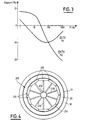
- FIG. 3 The evolution of the real part of the secondary field and the imaginary part of the secondary field, as a percentage of the primary field, for a given distance "a", as a function of the frequency, is shown in FIG. 3 attached.
- the curves in FIG. 3 make it possible to choose the frequency as a function of the sensitivity sought and of the geometry of the device.
- the system is placed on a robot 200 designed to continuously osculate the circumference of the pipe.
- the robot 200 preferably comprises several pads 210 fixed by generally radial arms 220 on a central pad holder 230, which pads 210 are applied along a circumference on the internal surface of the pipe.
- Each shoe 210 has one or more measurement sensors 110, 120.
- Each coil 110 carried by a shoe 210 is connected to the generator 114 placed on the shoe holder 230.
- each coil 120 carried by a pad 210 is connected to the measurement means 124 and to the storage and processing means 126 placed on the central pad holder 230.
- the generator 114 placed at the level of the pad holder 230 generates the electrical excitation signal continuously.
- slightly different frequencies are chosen for each of the devices so that simultaneous measurements can be made with all the devices located on the circumference.
- the robot 200 is moved slowly along the pipeline, for example of the order of 1m per second. The movement can be controlled manually or automatically by a motorized system.
- the present invention can also be applied for the control of pipes under load, on condition that the robot 200 can support it and for the control of bare steel pipes.
Landscapes
- Chemical & Material Sciences (AREA)
- Chemical Kinetics & Catalysis (AREA)
- Electrochemistry (AREA)
- Physics & Mathematics (AREA)
- Health & Medical Sciences (AREA)
- Life Sciences & Earth Sciences (AREA)
- Analytical Chemistry (AREA)
- Biochemistry (AREA)
- General Health & Medical Sciences (AREA)
- General Physics & Mathematics (AREA)
- Immunology (AREA)
- Pathology (AREA)
- Investigating Or Analyzing Materials By The Use Of Magnetic Means (AREA)
- Investigating Or Analyzing Materials By The Use Of Electric Means (AREA)
Abstract
Description
La présente invention concerne le domaine des dispositifs de contrôle de l'état de canalisations.The present invention relates to the field of devices for monitoring the condition of pipelines.
Plus précisément, la présente invention s'applique notamment, mais non exclusivement, au contrôle des canalisations en acier nu ou enrobé, notamment enrobé de béton précontraint, telles que les canalisations utilisées pour véhiculer de l'eau.More specifically, the present invention applies in particular, but not exclusively, to the control of bare or coated steel pipes, in particular coated with prestressed concrete, such as the pipes used to convey water.
La présente invention a pour but de détecter une éventuelle corrosion desdites canalisations.The object of the present invention is to detect possible corrosion of said pipes.
La technique la plus classique pour contrôler la qualité de canalisations non métalliques est d'utiliser un système de type radar.The most conventional technique for controlling the quality of non-metallic pipelines is to use a radar type system.
En revanche à ce jour, il n'existe aucun système industriel apte à contrôler l'état d'une canalisation métallique. En effet, la technique connue à base de radar ne permet pas le contrôle de canalisations en métal, notamment en acier, dans la mesure où celui-ci se montre trop bon réflecteur à l'égard des ondes électromagnétique générées par le système radar. De ce fait, à la connaissance de la Demanderesse, il n'existe pas à ce jour de système permettant de déceler des zones éventuelles de corrosion sur des conduites métalliques.However, to date, there is no industrial system capable of controlling the condition of a metal pipeline. Indeed, the known technique based on radar does not allow the control of metal pipes, in particular steel, insofar as the latter is too good a reflector with respect to the electromagnetic waves generated by the radar system. Therefore, to the knowledge of the Applicant, to date there is no system for detecting possible areas of corrosion on metal pipes.
La présente invention a maintenant pour but de proposer un système permettant de contrôler l'état de canalisations métalliques, notamment de canalisations en acier.The present invention now aims to provide a system for monitoring the condition of metal pipes, especially steel pipes.
Ce but est atteint selon la présente invention grâce à un système de contrôle comprenant :
- un dispositif électromagnétique par induction comportant un élément émetteur et un élément récepteur,
- un générateur électrique apte à appliquer un signal variable à l'élément émetteur,
- un moyen de mesure sensible au signal généré aux bornes de l'élément récepteur, et
- un moyen de traitement du signal mesuré aux bornes de l'élément récepteur, apte à déterminer la perméabilité magnétique de la canalisation et la conductivité ou la conductance électrique de celle-ci, par résolution à l'aide d'une méthode itérative d'un système d'équations non linéaires qui décrivent le comportement des composantes du champ magnétique.
- an electromagnetic induction device comprising a transmitter element and a receiver element,
- an electric generator capable of applying a variable signal to the transmitter element,
- a measurement means sensitive to the signal generated at the terminals of the receiving element, and
- a means of processing the signal measured at the terminals of the receiving element, capable of determining the magnetic permeability of the pipe and the conductivity or the electrical conductance of the latter, by resolution using an iterative method of a system of non-linear equations which describe the behavior components of the magnetic field.
Selon une caractéristique avantageuse de la présente invention, le capteur électromagnétique comprend deux bobines à axes coplanaires servant respectivement d'élément émetteur et d'élément récepteur.According to an advantageous characteristic of the present invention, the electromagnetic sensor comprises two coils with coplanar axes serving respectively as transmitting and receiving elements.
Selon une autre caractéristique avantageuse de la présente invention, le signal variable appliqué à l'élément émetteur est un signal électrique sinusoïdal.According to another advantageous characteristic of the present invention, the variable signal applied to the transmitter element is a sinusoidal electrical signal.
Il a déjà été proposé pour des procédés de prospection géophysique d'utiliser un dispositif comprenant une bobine émettrice recevant un signal électrique variable, généralement sinusoïdal, et une bobine réceptrice, afin de détecter des minéralisations massives conductrices situées à des profondeurs variant de quelques mètres à quelques centaines de mètres environ.It has already been proposed for geophysical prospecting methods to use a device comprising a transmitting coil receiving a variable electrical signal, generally sinusoidal, and a receiving coil, in order to detect massive conductive mineralizations located at depths varying from a few meters to a few hundred meters approximately.
Cette technique est connue pour la prospection géophysique sous le nom de procédé SLINGRAM et décrite dans tous les traites de géophysique appliquéeThis technique is known for geophysical prospecting under the name of SLINGRAM process and described in all treaties of applied geophysics
Selon la technique connue décrite dans ce document, on tente d'extraire, à partir des grandeurs mesurées aux bornes de la bobine réceptrice, la conductivité vraie (σi) de chaque formation géologique au voisinage du dispositif ou sa conductance (Ci=σi.ei, où ei représente son épaisseur), lorsqu'il s'agit d'une formation très conductrice et peu épaisse. Pour arriver à cette fin, dans le cas d'un sous-sol complexe, on utilise des signaux émetteurs de fréquence différentes couvrant une large gamme si l'on travaille dans le domaine fréquentiel (1, 2, 3, 4 décades ou plus) ; si l'on travaille dans le domaine temporel, on doit couvrir des phénomènes transitoires qui couvrent également plusieurs décades (de quelques microsecondes à quelques millisecondes).According to the known technique described in this document, an attempt is made to extract, from the quantities measured at the terminals of the receiving coil, the true conductivity (σ i ) of each geological formation in the vicinity of the device or its conductance (C i = σ i .e i , where e i represents its thickness), when the formation is very conductive and not very thick. To achieve this end, in the case of a complex basement, we use transmitter signals of different frequency covering a wide range if we work in the frequency domain (1, 2, 3, 4 or more decades) ; if one working in the time domain, we must cover transient phenomena which also cover several decades (from a few microseconds to a few milliseconds).
On a décrit par ailleurs dans le document "Parchas C. and Tabbagh A. 1978, Simultaneous measurements of electrical conductivity and magnetic susceptibility of the ground in electromagnetic prospecting, Archaeo - Physika 10, 682-691'', un dispositif semblable adapté pour la prospection archéologique. Le système décrit dans ce document, détermine simultanément deux caractéristiques physiques du sous-sol, la conductivité σ (en Siemens) et la perméabilité magnétique µ (en Henry/m). Pour des raisons de simplicité, l'équipement actuel mettant en oeuvre le principe décrit dans le document précité, travaille dans le domaine fréquentiel.We have also described in the document "Parchas C. and Tabbagh A. 1978, Simultaneous measurements of electrical conductivity and magnetic susceptibility of the ground in electromagnetic prospecting, Archaeo - Physika 10, 682-691 '', a similar device suitable for the Archaeological prospecting. The system described in this document simultaneously determines two physical characteristics of the subsoil, the conductivity σ (in Siemens) and the magnetic permeability µ (in Henry / m). implementing the principle described in the aforementioned document, works in the frequency domain.
La fréquence unique choisie est telle que les équations de diffusion de champ électromagnétique se simplifient. Ils travaillent dans le domaine asymptotique dit "des faibles nombres d'onde d'induction". Cette notion sera développée dans la partie théorique ci-après. Dans ce domaine, où les équations sont simples, comme il a été mentionné ci-dessus :
- la perméabilité magnétique (H) est extraite de la mesure de la Partie Réelle ou Partie en Phase de la composante du champ magnétique secondaire mesuré, tandis que
- la conductivité électrique (σ) est extraite de la mesure de la Partie Imaginaire ou Partie en Quadrature.
- the magnetic permeability (H) is extracted from the measurement of the Real Part or Phase Part of the component of the measured secondary magnetic field, while
- the electrical conductivity (σ) is extracted from the measurement of the Imaginary Part or Quadrature Part.
Plus précisément, le système connu pour prosepction archéologique comprend deux bobines à axes parallèles, obliques par rapport aux interfaces à contrôler, avec une distance "a", entre la bobine émettrice et la bobine réceptrice, égale à 1,50m. La fréquence utilisée est de 8040Hz. Cette fréquence conduit au domaine asymptotique des faibles nombres d'onde.
En effet, soit µ=µo=4π.10⁻⁷H/m
σ=10⁻¹S
on obtient |ka|=a(2πFµσ)1/2=0,12.More specifically, the known system for archaeological prosepction comprises two coils with parallel axes, oblique to the interfaces to be controlled, with a distance "a", between the transmitting coil and the receiving coil, equal to 1.50m. The frequency used is 8040Hz. This frequency leads to the asymptotic domain of low wave numbers.
Indeed, let µ = µo = 4π.10⁻⁷H / m
σ = 10⁻¹S
we get | ka | = a (2πFµσ) 1/2 = 0.12.
Cependant, on ne peut travailler dans le domaine asymptotique, tel que |ka|<1, pour le contrôle de canalisations métalliques, par exemple en acier.However, one cannot work in the asymptotic field, such as | ka | <1, for the control of metallic pipes, for example steel.
En effet, pour une canalisation en acier dont les caractéristiques sont déterminantes face à celles du béton et de l'encaissant soit
σ=10⁷S
µ=4π.10⁻⁵H/m
et en prenant des valeurs
a=10⁻²m
e=4.10⁻³m
qui seraient compatibles avec le contrôle de l'état de canalisations,
pour avoir |ka|=1, sachant que ka=(2πFµσea)1/²,
on obtient : F=3Hz.Indeed, for a steel pipe, the characteristics of which are decisive compared to those of the concrete and the casing, either
σ = 10⁷S
µ = 4π.10⁻⁵H / m
and taking values
a = 10⁻²m
e = 4.10⁻³m
which would be compatible with checking the condition of pipes,
to have | ka | = 1, knowing that ka = (2πFµσea) 1 / ²,
we get: F = 3Hz.
Une telle très basse fréquence de 3Hz n'est pas compatible avec le contrôle de canalisations. D'une part, elle exigerait pour permettre une sensibilité suffisante, un diamètre de bobine important, incompatible avec un écart a=10⁻²m entre les bobines. D'autre part, elle exigerait un temps de mesure inacceptable.Such a very low frequency of 3Hz is not compatible with the control of pipelines. On the one hand, it would require, to allow sufficient sensitivity, a large coil diameter, incompatible with a difference a = 10⁻²m between the coils. On the other hand, it would require an unacceptable measurement time.
Pour ces raisons, l'homme de l'art ne pouvait envisager de transposer la technique de prospection dite SLINGRAM et précisée par Pachas et Tabbagh au contrôle de canalisations métalliques.For these reasons, those skilled in the art could not envisage transposing the prospecting technique known as SLINGRAM and specified by Pachas and Tabbagh to the control of metal pipes.
D'autres caractéristiques, buts et avantages de la présente invention apparaîtront à la lecture de la description détaillée qui va suivre, et en regard des dessins annexés donnés à titre d'exemples non limitatifs et sur lesquels :
- la figure 1 représente une vue schématique d'un système conforme à la présente invention placé en regard d'une paroi de canalisation à contrôler,
- la figure 2 représente schématiquement cinq configurations possibles de bobines du dispositif capteur conforme à la présente invention,
- la figure 3 représente l'évolution de la partie réelle et de la partie imaginaire du champ magnétique secondaire rapportées au champ primaire pour l'une des configurations représentées figure 2 et pour les valeurs des paramètres donnés précédemment, en fonction de la fréquence d'excitation utilisée, et
- la figure 4 représente une vue schématique en coupe transversale, selon l'axe d'une canalisation, d'un système conforme à un mode de réalisation préférentiel de la présente invention.
- FIG. 1 represents a schematic view of a system according to the present invention placed opposite a pipe wall to be checked,
- FIG. 2 schematically represents five possible configurations of coils of the sensor device according to the present invention,
- FIG. 3 represents the evolution of the real part and the imaginary part of the secondary magnetic field related to the primary field for one of the configurations represented in FIG. 2 and for the values of the parameters given above, as a function of the excitation frequency used, and
- FIG. 4 represents a schematic view in transverse section, along the axis of a pipe, of a system according to a preferred embodiment of the present invention.
Comme on l'a indiqué précédemment et comme représenté sur la figure 1 annexée, la présente invention s'applique notamment au contrôle de l'état de canalisations en acier revêtu de béton, afin de détecter une éventuelle corrosion des canalisations.As indicated above and as shown in FIG. 1 attached, the present invention applies in particular to the control of the condition of steel pipes coated with concrete, in order to detect possible corrosion of the pipes.
Sur la figure 1 annexée, on a référencé 10 la paroi en acier de la canalisation et on a référencé respectivement 20 et 30 les enrobages de béton précontraint placés sur l'intérieur et sur l'extérieur du tubage d'acier 10. Les couches "tabulaires" de béton précontraints 20, 30 placées respectivement sur l'intérieur et sur l'extérieur de la canalisation en acier 10, ont une épaisseur typiquement de l'ordre de 4 à 5cm, tandis que la canalisation en acier a typiquement une épaisseur de l'ordre de 4mm.In the appended FIG. 1, the steel wall of the pipe is referenced 10 and the prestressed concrete coatings placed on the inside and on the outside of the
L'encaissant, c'est-à-dire le milieu environnant la canalisation est référencé 40 sur la figure 1.The receiving body, that is to say the medium surrounding the pipeline, is referenced 40 in FIG. 1.
La structure ainsi formée à étudier peut donc être considérée à l'échelle de dispositif comme une structure tabulaire à cinq couches, dont l'air situé à l'intérieur de la couche de béton 20, lorsque la canalisation est hors service.The structure thus formed to be studied can therefore be considered at device level as a structure tabular with five layers, including the air located inside the
Les caractéristiques physiques de chaque milieu sont appelées :
σi : conductivité électrique,
µi : perméabilité magnétique,
εi : permittivité diélectrique,
avec pour indice i :
o : pour la couche d'air située à l'intérieur de la couche de béton 20,
1 : pour la couche interne de béton 20,
2 : pour la canalisation en acier 10,
3 : pour la couche externe de béton 30,
4 : pour l'environnement 40.The physical characteristics of each medium are called:
σ i : electrical conductivity,
µ i : magnetic permeability,
ε i : dielectric permittivity,
with index i:
o: for the air layer located inside the
1: for the internal layer of
2: for
3: for the outer layer of
4: for the
Comme évoqué précédemment et comme montré sur la figure 1, le système de contrôle conforme à la présente invention comprend un dispositif capteur 100 conçu pour être placé de préférence à l'intérieur de la canalisation. Ce dispositif 100 comporte de préférence deux bobines 110, 120. Les deux bobines 110, 120, ont de préférence des axes 112, 122 coplanaires. La disposition des deux bobines 110, 120 peut faire l'objet d'un grand nombre de configurations.As mentioned above and as shown in FIG. 1, the control system according to the present invention comprises a
De préférence, la disposition des bobines 110, 120 est choisie dans l'une des cinq dispositions représentées sur la figure 2.Preferably, the arrangement of the
Plus précisément, ces cinq dispositions des deux bobines 110, 120, sont les suivantes sachant que émetteur et récepteur sont interchangeables du fait du théorème de réciprocité :
- Figure 2a :
bobines l'une émettrice 110ayant son axe 112 parallèle aux interfaces à contrôler et l'autre réceptrice 120, ayantson axe 122 perpendiculaire auxdites interfaces à contrôler, - Figure 2b :
bobines chacune son axe - Figure 2c :
bobines - Figure 2d : bobines 110, 120 ayant leurs axes 112, 122 parallèles entre eux et parallèles aux interfaces à contrôler,
- Figure 2e : bobines 110, 120 ayant leurs axes 112, 122 parallèles entre eux et obliques par rapport aux interfaces à contrôler.
- Figure 2a: coils 110, 120 perpendicular to each other, one
transmitter 110 having itsaxis 112 parallel to the interfaces to be controlled and theother receiver 120, having itsaxis 122 perpendicular to said interfaces to be checked, - FIG. 2b: coils 110, 120 each having its
axis - FIG. 2c:
coaxial coils axes - FIG. 2d: coils 110, 120 having their
axes - Figure 2e: coils 110, 120 having their
axes
Le mode de réalisation représenté sur la figure 2e peut être considéré comme une combinaison des modes de réalisation représentés sur les figures 2a à 2c.The embodiment shown in Figure 2e can be considered as a combination of the embodiments shown in Figures 2a to 2c.
Comme indiqué précédemment, de préférence dans toutes les configurations, les axes 112, 122 des bobines sont coplanaires.As indicated above, preferably in all configurations, the
De préférence, les deux bobines 110, 120 sont de structure identique. Elles sont multispires. Les deux bobines 110, 120 peuvent être réalisées par exemple par bobinage d'un fil fin de cuivre sur un support sans noyau réalisé à base de matière plastique par exemple ou sur un support avec noyau magnétique.Preferably, the two
Les bobines 110, 120 ont typiquement un diamètre de 1 à 4cm. Leur hauteur est également typiquement de l'ordre de 1 à 4cm.The
La distance entre les deux bobines 110, 120, est typiquement de l'ordre de 5 à 20cm, très avantageusement de l'ordre d'une dizaine de cm.The distance between the two
La distance a entre les deux bobines 110, 120, est typiquement de 1 à 5 fois, la distance séparant le capteur 100 de la paroi de canalisation 10 à contrôler, soit en l'espèce de 1 à 5 fois, l'épaisseur L1 de la couche intérieure de béton 20, additionnée de la distance h entre le dispositif 100 et la surface interne 22 de la couche intérieure de béton 20.The distance a between the two
Le dispositif capteur 100 est rendu étanche, lorsqu'il est placé dans une canalisation en charge, notamment dans de l'eau.The
La bobine 110 reçoit un signal électrique variable en provenance d'un générateur schématisé sous la référence 114 sur la figure 1. Le signal électrique issu du générateur 114 et appliqué à la bobine émettrice 110 est de préférence un signal sinusoïdal possèdant une fréquence comprise entre 1 et 1000Hz.The
En variante, le signal électrique issu du générateur 114 peut être du type créneau ou échelon, ou toute autre forme similaire pourvu que la gamme des temps ou des fréquences soit adaptée.As a variant, the electrical signal coming from the
Le courant électrique appliqué par le générateur 114 à la bobine 110 crée dans l'air et dans le milieu environnant non conducteur, un champ magnétique alternatif en phase avec le courant primaire dit champ primaire Hp.The electric current applied by the
Ce champ primaire, variable dans le temps, crée par induction dans l'acier très conducteur 10 et dans le milieu environnant éventuellement conducteur 40, des courants électriques variables, qui eux-mêmes créent un champ magnétique secondaire Hs.This primary field, variable in time, creates by induction in the highly
Ce champ magnétique secondaire Hs va dépendre de la corrosion de la canalisation 10, du fait que cette corrosion diminue la conductivité σ (Siemens/m) et l'épaisseur e (mm), donc la conductance C = σ.e (millisiemens). La corrosion de la canalisation affecte également la perméabilité magnétique de l'acier.This secondary magnetic field Hs will depend on the corrosion of the
La bobine réceptrice 120 permet de mesurer la composante axiale du champ magnétique total Ht, c'est-à-dire la superposition du champ primaire et du champ secondaire.The receiving
Le système conforme à la présente invention comprend en outre un élément 124 de mesure du signal généré aux bornes de la bobine réceptrice 120 et un moyen 126 de traitement du signal mesuré par le moyen 124.The system according to the present invention further comprises an
Le moyen de traitement 126 est adapté pour déterminer la conductivité électrique ou la conductance de la paroi 10 ainsi que la perméabilité magnétique de celle-ci par résolution des équations non linéaires du système donnant le champ total en fonction de la conductance et de la perméabilité de la canalisation. Cette résolution est opérée par une méthode itérative, telle que de la méthode de Newton-Raphson décrite dans le document "Ortega J. and Rheniboldt W. , 1970, Iterative Solution of Non Linear Equations in Several Variables New York, Academic Press".The processing means 126 is adapted to determine the electrical conductivity or the conductance of the
Dans l'étude des phénomènes électromagnétiques, on définit, le nombre d'onde Ki dans chaque formation tel que![]()
pour un signal sinusoïdal de pulsation ω=2πF où F est la fréquence.In the study of electromagnetic phenomena, we define the wave number K i in each formation such that ![]()
for a sinusoidal signal of pulsation ω = 2πF where F is the frequency.
Dans la gamme de fréquence dans laquelle nous travaillons : ωε<<σ si bien que :![]()
![]()
On définit la constante de propagation qui, compte-tenu de la symétrie, se réduit à :![]()
où λ est une constante dite d'intégration qui varie de -∞ à +∞.We define the propagation constant which, taking into account the symmetry, is reduced to: ![]()
where λ is a so-called integration constant which varies from -∞ to + ∞.
Les équations résolues par le moyen 126 font intervenir les caractéristiques physiques des milieux (béton 20, 30, canalisation métallique 10 et encaissant 40), ainsi que les grandeurs mesurées H.The equations solved by the
Les équations correspondantes pour les cinq configurations représentées sur les figures 2a à 2d sont les suivantes :The corresponding equations for the five configurations shown in Figures 2a to 2d are the following :


Pour la configuration sur la figure 2e, le moyen 126 résoud une équation qui correspond à une combinaison des équations ci-dessus.For the configuration in FIG. 2e, the
Dans les équations qui précèdent :
Hz est la composante du champ perpendiculaire à l'interface à contrôler,
Hx est une composante du champ parallèle à l'interface référencée par rapport à l'émetteur,
m est le moment de l'émetteur en Axm²
a est la distance émetteur 110 et récepteur 120
h est la distance entre le plan du dispositif 100 et la surface 22 de la couche intérieure de béton 20
λ est une constante d'intégration qui varie de -∞ à +∞.In the above equations:
Hz is the component of the field perpendicular to the interface to be controlled,
Hx is a component of the field parallel to the interface referenced with respect to the transmitter,
m is the time of the transmitter in Axm²
a is the distance from
h is the distance between the plane of the
λ is an integration constant which varies from -∞ to + ∞.
Ces intégrales ne peuvent être calculées que numériquement avec un pas en λ choisi en fonction de la précision souhaitée.
J₀ (λa) et J₁ (λa) sont les fonctions de Bessel d'ordre 0 et d'ordre 1.
rTE est le coefficient de réflexion caractéristique de la structure tabulaire à étudier ; il se calcule par une formule de récurrence à partir des caractéristiques de chaque formation :![]()
avec![]()
![]()
et![]()
dans l'encaissant 40These integrals can only be calculated numerically with a step in λ chosen as a function of the desired precision.
J₀ (λa) and J₁ (λa) are the Bessel functions of
r TE is the characteristic reflection coefficient of the tabular structure to be studied; it is calculated by a recurrence formula from the characteristics of each formation: ![]()
with ![]()
![]()
and ![]()
in
La résolution numérique des équations ci-dessus à l'aide de la méthode de Newton-Raphson, pour extraire la conductivité σ₂ de l'acier 10 et la perméabilité magnétique µ₂ de l'acier 10, requiert de connaitre les caractéristiques σi, µi, et ei de l'air, du béton et de l 'encaissant.The numerical resolution of the above equations using the Newton-Raphson method, to extract the conductivity σ₂ of
Ces caractéristiques peuvent être connues par expérience ou par des mesures in situ préalables.These characteristics can be known by experience or by prior in situ measurements.
On a typiquement :
σ₀ = 0
µ₀ = 4 π. 10⁻⁷ H/m
10⁻⁴ S < σ₁=σ₃ < 10⁻² S
µ₁ = µ₂ = µ₀
10⁻³ S < σ₄ < 10⁻¹S
µ₄ = µ₀
e₁ = e₃ = 4cm
e₂ = 4 mm
e₄ → ∞We typically have:
σ₀ = 0
µ₀ = 4 π. 10⁻⁷ H / m
10⁻⁴ S <σ₁ = σ₃ <10⁻² S
µ₁ = µ₂ = µ₀
10⁻³ S <σ₄ <10⁻¹S
µ₄ = µ₀
e₁ = e₃ = 4cm
e₂ = 4 mm
e₄ → ∞
Les caractéristiques de l'émetteur 100 sont connues :
m = n.S.I
n représentant le nombre de spires de la bobine 110
S représentant la surface de la bobine 110 et
I représentant l'intensité du courant appliqué à la bobine émettrice 110
a = 5 à 20 cmThe characteristics of the
m = nSI
n representing the number of turns of the
S representing the surface of the
I representing the intensity of the current applied to the emitting
a = 5 to 20 cm
Les grandeurs mesurées en mV aux bornes de la bobine secondaire 120 sont transformées en valeurs de champ magnétique en A/m.The magnitudes measured in mV across the terminals of the
Lorsque le signal appliqué à la bobine émettrice 110 comprend une seule fréquence, le moyen 126 sépare la composante réelle du signal mesurée, c'est à dire la composante de ce signal en phase avec le signal issu du générateur 114 et la composante imaginaire du signal mesuré, c'est à dire la composante de ce signal en quadrature avec le signal issu du générateur 114, pour former un système à deux équations non linéaires.When the signal applied to the emitting
Plus précisément encore, de préférence, selon la présente invention, le générateur 114 applique à la bobine émettrice 110 deux fréquences comprises entre 1 et 1000Hz, différentes, mais proches.More precisely still, preferably, according to the present invention, the
La mesure des signaux induits aux bornes de la bobine secondaire 120 permet alors de résoudre un système de quatre équations si l'on sépare la composante réelle et la composante imaginaire du signal mesuré pour chacune des deux fréquences et si l'on tient compte de chacune de ces deux composantes réelles et deux composantes imaginaires.The measurement of the signals induced at the terminals of the
En variante on peut utiliser deux fréquences d'excitation, mais n'exploiter que les parties réelles ou les parties imaginaires des signaux mesuré, ce qui conduit à un système à deux équations.As a variant, two excitation frequencies can be used, but only exploit the real parts or the imaginary parts of the signals measured, which leads to a system with two equations.
En résumé, le processus de traitement mis en oeuvre par le moyen 126 est de préférence le suivant :
- introduction, dans les équations, des caractéristiques connues de l'environnement (conductivité et perméabilité magnétique de l'environnement) et des caractéristiques du champ primaire,
- introduction des valeurs mesurées, par exemple 4 valeurs ReHf₁, ImHf₁, ReHf₂, ImHf₂, si l'on utilise 2 fréquences f₁, f₂ et si l'on sépare partie réelle Re et partie imaginaire Im,
- résolution des équations pour calculer la conductance de la canalisation à contrôler et sa perméabilité.
- introduction, into the equations, of the known characteristics of the environment (conductivity and magnetic permeability of the environment) and of the characteristics of the primary field,
- introduction of the measured values, for example 4 values ReHf₁, ImHf₁, ReHf₂, ImHf₂, if 2 frequencies f₁, f₂ are used and if the real part Re and imaginary part Im are separated,
- solving equations to calculate the conductance of the pipe to be checked and its permeability.
Une fois les équations ainsi résolues, le système délivre pour chaque position du dispositif les valeurs de la perméabilité et de la conductance. Si le dispositif se déplace le long de la circonférence et le long d'un diamètre ou préférentiellement si plusieurs dispositifs permettent des mesures simultanées le long d'une circonférence et que l'ensemble se déplace le long des canalisations, on peut délivrer deux cartes de la canalisation contrôlée : une carte de conductance (c=σ.e exprimé en millisiemens) et une carte de perméabilité magnétique relative (µ).Once the equations have thus been resolved, the system delivers the permeability and conductance values for each position of the device. If the device moves along the circumference and along a diameter or preferably if several devices allow simultaneous measurements along a circumference and the whole moves along the pipes, two cards can be issued. the controlled pipeline: a conductance map (c = σ.e expressed in millisiemens) and a relative magnetic permeability map (µ).
Toute anomalie de la conductance et/ou de la perméabilité magnétique est un indice de corrosion.Any abnormality in conductance and / or magnetic permeability is an indication of corrosion.
On a représenté sur la figure 3 annexée l'évolution de la partie réelle du champ secondaire et de la partie imaginaire du champ secondaire, en pourcentage du champ primaire, pour une distance "a" donnée, en fonction de la fréquence. Les courbes de la figure 3 permettent de choisir la fréquence en fonction de la sensibilité recherchée et de la géométrie du dispositif.The evolution of the real part of the secondary field and the imaginary part of the secondary field, as a percentage of the primary field, for a given distance "a", as a function of the frequency, is shown in FIG. 3 attached. The curves in FIG. 3 make it possible to choose the frequency as a function of the sensitivity sought and of the geometry of the device.
Selon un mode de mise en oeuvre préférentiel illustré schématiquement sur la figure 4, le système est placé sur un robot 200 conçu pour osculter de manière continue la circonférence de la canalisation.According to a preferred embodiment illustrated schematically in Figure 4, the system is placed on a
A cette fin, le robot 200 comprend de préférence plusieurs patins 210 fixés par des bras 220 généralement radiaux sur un porte-patins central 230, lesquels patins 210 s'appliquent suivant une circonférence sur la surface interne de la canalisation. Chaque patin 210 comporte un ou plusieurs capteurs de mesure 110, 120. Chaque bobine 110 portée par un patin 210 est reliée au générateur 114 placé sur le porte patins 230.To this end, the
De même chaque bobine 120 portée par un patin 210 est reliée aux moyens de mesure 124 et aux moyens 126 de mémorisation et de traitement placés sur le porte-patins central 230.Similarly, each
Le générateur 114 placé au niveau du porte-patins 230 génère le signal électrique d'excitation de façon continue. Préférentiellement, des fréquences légèrement différentes sont choisies pour chacun des dispositifs de façon à pouvoir effectuer des mesures simultanées avec tous les dispositifs situés sur la circonférence. Le robot 200 est déplacé lentement le long de la canalisation, par exemple de l'ordre de 1m par seconde. Le déplacement peut être commandé manuellement ou automatiquement par un système motorisé.The
Bien entendu la présente invention n'est pas limitée au mode de réalisation particulier qui vient d'être décrit mais s'étend à toute variante conforme à son esprit.Of course the present invention is not limited to the particular embodiment which has just been described but extends to any variant in accordance with its spirit.
Par exemple, on peut envisager de remplacer le capteur à deux bobines précédememnt décrit en regard de la figure 1, par un capteur à bobine unique, en mesurant les variations d'impédance de ladite bobine.For example, it is conceivable to replace the sensor with two coils previously described with reference to FIG. 1, by a sensor with a single coil, by measuring the variations in impedance of said coil.
On peut aussi appliquer la présente invention pour le contrôle des canalisations en charge, à la condition que le robot 200 puisse le supporter et pour le contrôle de canalisations en acier nu.The present invention can also be applied for the control of pipes under load, on condition that the
Claims (15)


Hx est le champ parallèle à l'interface à contrôler,
m est le moment de l'émetteur en Axm²,
a est la distance émetteur (110) et récepteur (120),
h est la distance entre le plan du dispositif (100) et la surface (22) de la couche intérieure de béton (20),
λ est une constante d'intégration qui varie de -∞ à +∞,
Jo (λa) et Ji (λa) sont les fonctions de Bessel d'ordre 0 et d'ordre 1,
rTE est le coefficient de réflexion caractéristique de la structure tabulaire à étudier calculé par une formule de récurrence à partir des caractéristiques de chaque formation :
Hx is the field parallel to the interface to control,
m is the time of the transmitter in Axm²,
a is the transmitter (110) and receiver (120) distance,
h is the distance between the plane of the device (100) and the surface (22) of the inner layer of concrete (20),
λ is an integration constant which varies from -∞ to + ∞,
Jo (λa) and Ji (λa) are the Bessel functions of order 0 and order 1,
r TE is the characteristic reflection coefficient of the tabular structure to be studied calculated by a recurrence formula from the characteristics of each formation:
Applications Claiming Priority (2)
| Application Number | Priority Date | Filing Date | Title |
|---|---|---|---|
| FR9208941A FR2693797B1 (en) | 1992-07-20 | 1992-07-20 | Pipeline control system, especially of bare or coated steel pipes. |
| FR9208941 | 1992-07-20 |
Publications (1)
| Publication Number | Publication Date |
|---|---|
| EP0580485A1 true EP0580485A1 (en) | 1994-01-26 |
Family
ID=9432064
Family Applications (1)
| Application Number | Title | Priority Date | Filing Date |
|---|---|---|---|
| EP93401851A Withdrawn EP0580485A1 (en) | 1992-07-20 | 1993-07-19 | System for the inspection of canalisation, especially of steel, jacketed or not |
Country Status (4)
| Country | Link |
|---|---|
| EP (1) | EP0580485A1 (en) |
| JP (1) | JPH06317562A (en) |
| CA (1) | CA2100822A1 (en) |
| FR (1) | FR2693797B1 (en) |
Cited By (3)
| Publication number | Priority date | Publication date | Assignee | Title |
|---|---|---|---|---|
| FR2724019A1 (en) * | 1994-08-31 | 1996-03-01 | Intercontrole Sa | Digital analysis technique esp. for monitoring by Foucault currents and digital demodulation |
| WO2000042425A1 (en) * | 1999-01-13 | 2000-07-20 | Rock Solid Research Pty. Ltd. | A subsurface pipeline inspection probe |
| WO2002061412A2 (en) * | 2001-01-29 | 2002-08-08 | Pure Technologies Ltd. | Electromagnetic analysis of concrete tensioning strands |
Families Citing this family (3)
| Publication number | Priority date | Publication date | Assignee | Title |
|---|---|---|---|---|
| DE69122801T2 (en) * | 1990-04-24 | 1997-03-20 | Nippon Denso Co | AC generator having a plurality of independent three-phase windings |
| JP4982075B2 (en) * | 2005-11-26 | 2012-07-25 | マークテック株式会社 | Eddy current testing probe |
| JP5188088B2 (en) * | 2007-03-30 | 2013-04-24 | 川崎重工業株式会社 | Failure prediction devices such as reducers |
Citations (4)
| Publication number | Priority date | Publication date | Assignee | Title |
|---|---|---|---|---|
| EP0260355A1 (en) * | 1985-03-29 | 1988-03-23 | Nippon Kokan Kabushiki Kaisha | Apparatus for detecting inner surface flaw of each pipe constituting pipeline |
| EP0370691A1 (en) * | 1988-11-16 | 1990-05-30 | Nnc Limited | Non-destructive examination using eddy current |
| EP0392295A1 (en) * | 1989-04-13 | 1990-10-17 | Siemens Aktiengesellschaft | Eddy current probe for testing tubes in a steam generator |
| EP0449753A1 (en) * | 1990-03-26 | 1991-10-02 | Vallourec Industries | Method and apparatus for inspecting metallic pipes by means of eddy currents |
Family Cites Families (1)
| Publication number | Priority date | Publication date | Assignee | Title |
|---|---|---|---|---|
| JPS63124209A (en) * | 1986-11-12 | 1988-05-27 | Sanyo Electric Co Ltd | Inspecting method for characteristics of magnetic head |
-
1992
- 1992-07-20 FR FR9208941A patent/FR2693797B1/en not_active Expired - Fee Related
-
1993
- 1993-07-19 CA CA 2100822 patent/CA2100822A1/en not_active Abandoned
- 1993-07-19 JP JP17837893A patent/JPH06317562A/en active Pending
- 1993-07-19 EP EP93401851A patent/EP0580485A1/en not_active Withdrawn
Patent Citations (4)
| Publication number | Priority date | Publication date | Assignee | Title |
|---|---|---|---|---|
| EP0260355A1 (en) * | 1985-03-29 | 1988-03-23 | Nippon Kokan Kabushiki Kaisha | Apparatus for detecting inner surface flaw of each pipe constituting pipeline |
| EP0370691A1 (en) * | 1988-11-16 | 1990-05-30 | Nnc Limited | Non-destructive examination using eddy current |
| EP0392295A1 (en) * | 1989-04-13 | 1990-10-17 | Siemens Aktiengesellschaft | Eddy current probe for testing tubes in a steam generator |
| EP0449753A1 (en) * | 1990-03-26 | 1991-10-02 | Vallourec Industries | Method and apparatus for inspecting metallic pipes by means of eddy currents |
Non-Patent Citations (1)
| Title |
|---|
| PATENT ABSTRACTS OF JAPAN vol. 12, no. 380 (P-769)12 Octobre 1988 & JP-A-63 124 209 ( SANYO ) 27 Mai 1988 * |
Cited By (9)
| Publication number | Priority date | Publication date | Assignee | Title |
|---|---|---|---|---|
| FR2724019A1 (en) * | 1994-08-31 | 1996-03-01 | Intercontrole Sa | Digital analysis technique esp. for monitoring by Foucault currents and digital demodulation |
| WO2000042425A1 (en) * | 1999-01-13 | 2000-07-20 | Rock Solid Research Pty. Ltd. | A subsurface pipeline inspection probe |
| US6573721B1 (en) | 1999-01-13 | 2003-06-03 | Rock Solid Research Pty. Ltd. | Time domain electromagnetic analysis and inspection system for conduits |
| US7042223B2 (en) | 1999-01-13 | 2006-05-09 | Rock Solid Research Pty. Ltd. | Time domain electromagnetic analysis and inspection system for conduits |
| WO2002061412A2 (en) * | 2001-01-29 | 2002-08-08 | Pure Technologies Ltd. | Electromagnetic analysis of concrete tensioning strands |
| WO2002061412A3 (en) * | 2001-01-29 | 2004-07-08 | Pure Technologies Ltd | Electromagnetic analysis of concrete tensioning strands |
| US6781369B2 (en) | 2001-01-29 | 2004-08-24 | Pure Technologies Ltd. | Electromagnetic analysis of concrete tensioning wires |
| US6791318B2 (en) | 2001-01-29 | 2004-09-14 | Pure Technologies Ltd. | Electromagnetic analysis of concrete tensioning wires |
| EP2458376A3 (en) * | 2001-01-29 | 2012-10-03 | Pure Technologies Ltd | Electromagnetic analysis of concrete tensioning wires |
Also Published As
| Publication number | Publication date |
|---|---|
| CA2100822A1 (en) | 1994-01-21 |
| FR2693797B1 (en) | 1994-10-21 |
| FR2693797A1 (en) | 1994-01-21 |
| JPH06317562A (en) | 1994-11-15 |
Similar Documents
| Publication | Publication Date | Title |
|---|---|---|
| EP0608230B1 (en) | Dynamic and contactless measurement of displacement or permittivity using a capacitive sensor | |
| EP0215695A1 (en) | Process for localizing an object and determining its orientation in space, and apparatus therefor | |
| CA1322395C (en) | Microwave transmitting-receiving device for use in buried object imaging | |
| FR2569859A1 (en) | METHOD AND DEVICE FOR DIAGRAPHY FOR ACOUSTIC INSPECTION OF A SURFACE WITH TUBING | |
| FR2654214A1 (en) | EDGE EDGE IMAGE FORMATION USING A PHASE DIFFERENCE DETECTION. | |
| WO2005096020A1 (en) | Method and apparatus for deriving a calibration filter for electromagnetic data | |
| JP2009539086A (en) | Method for determining film thickness of conductive coating on conductive substrate | |
| FR2734058A1 (en) | AMMETER | |
| EP0290513B1 (en) | Method for detecting thickness variations in the wall of a current conducting tubular body | |
| FR2633971A1 (en) | DEVICE AND METHOD FOR DETERMINING IN DRILLING AND AZIMUT OF A DISCONTINUOUS LAYER IN A HOMOGENEOUS ENVIRONMENT | |
| EP0580485A1 (en) | System for the inspection of canalisation, especially of steel, jacketed or not | |
| FR2795521A1 (en) | Study of resistivity of geological formation around borehole with metal casing, comprises applying current to casing, shunting current, and deducing leakage current from difference of voltage drops | |
| EP1666923A1 (en) | Procedure for locating mobile magnetic targets | |
| WO2011091932A1 (en) | Method for estimating defects in an object and device for implementing same | |
| FR2550628A1 (en) | METHOD AND DEVICE FOR MEASURING THE INITIAL PERMEABILITY OF FERRIIMAGNETIC MATERIALS IN A BROADBAND OF FREQUENCIES | |
| RU2733095C2 (en) | Method of three-dimensional objects searching by tm-polarization geoelectrics methods | |
| EP0441074B1 (en) | Inductive sensor and device for measuring displacements of a movable object | |
| EP0722096B1 (en) | Device for mapping a medium by induction measurement | |
| EP0422985B1 (en) | Process and device for the detection of earth magnetic field inversions by measurements in a borehole | |
| FR3044780A1 (en) | ||
| FR2740168A1 (en) | METHOD AND DEVICE FOR MEASURING GEOMETRIC CHARACTERISTICS OF A WELL, IN PARTICULAR A WELL OF HYDROCARBON | |
| WO2002001145A1 (en) | Method for measuring the thickness of a hollow vane wall | |
| EP0200619B1 (en) | Apparatus for measuring the level of electrically conductive material within a container, and applications thereof | |
| Lemistre et al. | Electromagnetic localization of defects in carbon epoxy composite materials | |
| FR2476831A1 (en) | DEVICE FOR NON-DESTRUCTIVE MEASUREMENT OF THE THICKNESS OF A SURFACE LAYER OF A BODY SUBJECT TO A TREATMENT MODIFYING THE STRUCTURE OF THIS SURFACE |
Legal Events
| Date | Code | Title | Description |
|---|---|---|---|
| PUAI | Public reference made under article 153(3) epc to a published international application that has entered the european phase |
Free format text: ORIGINAL CODE: 0009012 |
|
| AK | Designated contracting states |
Kind code of ref document: A1 Designated state(s): DE ES FR GB IT NL |
|
| 17P | Request for examination filed |
Effective date: 19940530 |
|
| 17Q | First examination report despatched |
Effective date: 19960201 |
|
| GRAG | Despatch of communication of intention to grant |
Free format text: ORIGINAL CODE: EPIDOS AGRA |
|
| GRAH | Despatch of communication of intention to grant a patent |
Free format text: ORIGINAL CODE: EPIDOS IGRA |
|
| STAA | Information on the status of an ep patent application or granted ep patent |
Free format text: STATUS: THE APPLICATION IS DEEMED TO BE WITHDRAWN |
|
| 18D | Application deemed to be withdrawn |
Effective date: 19970424 |