EP0576276A1 - Prepayment water supply system - Google Patents
Prepayment water supply system Download PDFInfo
- Publication number
- EP0576276A1 EP0576276A1 EP93304918A EP93304918A EP0576276A1 EP 0576276 A1 EP0576276 A1 EP 0576276A1 EP 93304918 A EP93304918 A EP 93304918A EP 93304918 A EP93304918 A EP 93304918A EP 0576276 A1 EP0576276 A1 EP 0576276A1
- Authority
- EP
- European Patent Office
- Prior art keywords
- valve
- token
- signals
- memory
- water
- Prior art date
- Legal status (The legal status is an assumption and is not a legal conclusion. Google has not performed a legal analysis and makes no representation as to the accuracy of the status listed.)
- Granted
Links
Images
Classifications
-
- G—PHYSICS
- G07—CHECKING-DEVICES
- G07F—COIN-FREED OR LIKE APPARATUS
- G07F7/00—Mechanisms actuated by objects other than coins to free or to actuate vending, hiring, coin or paper currency dispensing or refunding apparatus
- G07F7/08—Mechanisms actuated by objects other than coins to free or to actuate vending, hiring, coin or paper currency dispensing or refunding apparatus by coded identity card or credit card or other personal identification means
- G07F7/0866—Mechanisms actuated by objects other than coins to free or to actuate vending, hiring, coin or paper currency dispensing or refunding apparatus by coded identity card or credit card or other personal identification means by active credit-cards adapted therefor
-
- F—MECHANICAL ENGINEERING; LIGHTING; HEATING; WEAPONS; BLASTING
- F16—ENGINEERING ELEMENTS AND UNITS; GENERAL MEASURES FOR PRODUCING AND MAINTAINING EFFECTIVE FUNCTIONING OF MACHINES OR INSTALLATIONS; THERMAL INSULATION IN GENERAL
- F16K—VALVES; TAPS; COCKS; ACTUATING-FLOATS; DEVICES FOR VENTING OR AERATING
- F16K29/00—Arrangements for movement of valve members other than for opening and closing the valve, e.g. for grinding-in, for preventing sticking
-
- G—PHYSICS
- G07—CHECKING-DEVICES
- G07F—COIN-FREED OR LIKE APPARATUS
- G07F15/00—Coin-freed apparatus with meter-controlled dispensing of liquid, gas or electricity
-
- G—PHYSICS
- G07—CHECKING-DEVICES
- G07F—COIN-FREED OR LIKE APPARATUS
- G07F17/00—Coin-freed apparatus for hiring articles; Coin-freed facilities or services
- G07F17/0014—Coin-freed apparatus for hiring articles; Coin-freed facilities or services for vending, access and use of specific services not covered anywhere else in G07F17/00
-
- G—PHYSICS
- G07—CHECKING-DEVICES
- G07F—COIN-FREED OR LIKE APPARATUS
- G07F7/00—Mechanisms actuated by objects other than coins to free or to actuate vending, hiring, coin or paper currency dispensing or refunding apparatus
- G07F7/08—Mechanisms actuated by objects other than coins to free or to actuate vending, hiring, coin or paper currency dispensing or refunding apparatus by coded identity card or credit card or other personal identification means
- G07F7/0873—Details of the card reader
Definitions
- This invention relates to prepayment water supply systems, and is more particularly but not exclusively concerned with prepayment water metering systems based upon the prepayment systems disclosed in our United Kingdom Patents Nos. 2 153 573 and 2 191 622.
- the prepayment systems described in our United Kingdom Patent Nos 2 153 573 and 2 191 622 allow access to a metered commodity, and comprise a prepayment token in the form of key having a memory, a receptacle for the key (the receptacle typically forming part of a meter arranged to meter the commodity), and a circuit (also typically forming part of the meter) for allowing access to the commodity only when authorised by predetermined data read from the key memory.
- the data in the key memory is typically entered into the memory by inserting the key into a receptacle in a vending machine, typically located at the commodity supplier's premises, the machine then entering the data in return for payment, eg via a coin or bank note accepting unit forming part of the machine.
- the data typically includes credit data representative of the monetary amount paid, and data representative of tariff information and one or more unique identification codes.
- the circuit in the meter reads the data from the key, and permits the supply of the commodity to continue until the credit represented by the credit data is exhausted, at which point it discontinues the supply.
- a prepayment water supply system comprising a prepayment token having a memory, and supply control means including an electrically-operable valve for controlling the supply of the water, a receptacle for receiving the token, and a circuit coupled to the receptacle and to the valve and responsive to credit data read from the token memory to close the valve when an amount of water or a time period determined by said credit data has been supplied or has elapsed, the circuit being operative during the period prior to the insertion of a token having fresh credit data in its memory into the receptacle (during which period the valve is closed or supposed to be closed) to send from time to time a pair of signals to respectively re-open and substantially immediately reclose the valve.
- the pairs of signals may be sent at predetermined time intervals, in which case they serve primarily to reduce the possibility of the valve becoming stuck in its closed state when this closed state would otherwise last for a prolonged period.
- the supply control means includes a metering unit for metering the water
- such a pair of signals may be sent in response to the detection by the metering unit of a predetermined non-zero flow, since such detection is indicative of possibly fraudulent re-opening of the valve.
- the circuit preferably includes means for storing a signal representative of such detection as an indication of possible fraud, and subsequent such pairs of signals are preferably sent at preselected time intervals if said flow continues to be detected (rather than in direct response to subsequent detections of the flow).
- a prepayment water supply system comprising a prepayment token having a memory, and supply control means including an electrically-operable valve for controlling the supply of the water, a receptacle for receiving the token, and a circuit coupled to the receptacle and to the valve and responsive to credit data read from the token memory to close the valve when an amount of water or a time period determined by said credit data has been supplied or has elapsed, the circuit being operative when the valve has remained in one of its states for more than a given amount of time to send a pair of signals to respectively switch the valve to its other state and substantially immediately switch it back to said one state.
- such a pair of signals is typically sent if the valve remains in one state for more than seven days.
- the prepayment water metering system shown in the drawing is intended for installation in a water consumer's premises, and is closely based on the system described in our United Kingdom Patent No. 2 191 622 (which was in turn a development of the system described in our United Kingdom Patent No. 2 153 573).
- the system comprises a key 10, known as a customer key, containing a non-volatile memory such as an EEPROM, and a prepayment unit 12 having a receptacle 14 for receiving the key 10.
- a key 10 known as a customer key
- a prepayment unit 12 having a receptacle 14 for receiving the key 10.
- the physical form of the key 10 and the receptacle 12 can be as described in our United Kingdom Patent No. 2 191 883.
- a key interface circuit 16 coupled to a microprocessor 18.
- the microprocessor 18 is coupled in turn to another non-volatile memory 20 in the form of an EEPROM, to a clock 22 and to a display 23, all forming part of the unit 12.
- the microprocessor 18 is also coupled to a flow meter 24 connected in the main water inlet pipe 26 to the consumer's premises, and to a solenoid-operated valve 28 also connected in the pipe 26.
- the meter 24 and the valve 28 are preferably mounted in a common housing (not shown), and are connected to the unit 12 via an electrical cable.
- the system operates substantially as described in our United Kingdom Patents Nos. 2 153 574 and 2 191 622.
- the consumer takes the key 10 to a vending machine, typically located in or at a post office or other readily accessible premises, and inserts the key 10 into a receptacle, similar to the receptacle 14, in the machine.
- the consumer then inserts coins or bank notes into the machine, which, having read the key memory, responds by writing credit data representative of the amount of credit purchased into the key memory, along with tariff data representative of the current water supply tariff or tariffs and pass number data indicative of how many times the key has been used.
- the key memory typically already contains identification data uniquely identifying the key, the meter or prepayment unit with which it is to be used and the consumer, all of which identification data was entered when the key 10 was first issued to the consumer.
- the consumer Having charged the key 10 with credit, the consumer returns home and inserts the key into the receptacle 14.
- the microprocessor 18 also writes the current reading or readings of the meter 24, which are stored in the memory 20, along with the time and date to which the readings relate, into the key memory, substantially as described in United Kingdom Patent No 2 191 622.
- the microprocessor 18 is additionally programmed to periodically produce, in the period after the closure of the valve 28 and before the insertion of a key 10 containing fresh credit (ie the period when the valve is closed or supposed to be closed), a pair of signals which respectively re-open and then substantially immediately re-close the valve, typically at predetermined time intervals. This tends to ensure that the valve 28 does not become stuck in its closed state when that closed state would otherwise be of prolonged duration, eg more than seven days.
- the microprocessor 18 is further programmed to produce such a pair of signals in response to the production by the meter 24 of a predetermined number of flow pulses in a given time, indicating a predetermined non-zero flow, during the aforementioned period when the valve 28 is closed or supposed to be closed, since such pulse production is an indication that the valve may have been fraudulently caused to re-open (ie without the insertion of a key 10 containing fresh credit).
- the predetermined non-zero flow is selected to be just above the maximum flow which can pass through the by-pass conduit 30, since it will be appreciated that the by-pass flow is in fact metered by the meter 24.
- Such pairs of signals are preferably produced by the microprocessor 18 at predetermined time intervals rather than in response to the subsequent production by the meter 24 of another set of the predetermined number of flow pulses, since this enables the number of such pairs of signals to be kept to a predetermined, relatively low level, thus avoiding excessive power consumption where the unit 12 is battery powered (as is normally the case in a water metering context).
- the microprocessor 18 When the microprocessor 18 detects the existence of the predetermined non-zero flow in the circumstances outlined above, it additionally produces and stores in the EEPROM 20 a signal indicating a possible fraud.
- microprocessor 18 is also programmed such that, if the valve 28 remains in its open state for more than seven days, the microprocessor sends a pair of signals which respectively close it and then substantially immediately re-open it, so reducing the possibility of the valve sticking in its open state.
- the by-pass conduit 30 can be replaced by a conduit formed in the body of the valve 28, or even in the valve closure member of the valve 28.
- the by-pass conduit 30 can by-pass the meter 24 as well as the valve 28, in which case the predetermined non-zero flow which the microprocessor 18 is programmed to detect can be lower, ie close to zero.
- the by-pass conduit 30 can be omitted altogether, especially if a relatively long duration emergency facility is provided.
- the key 10 need not have the physical form of a key, but can instead be constituted for example by a so-called "smart card” or by a magnetic card.
- the water supply can be pre-paid for on a timed basis, rather than on a metered basis (ie a given amount of credit permits supply for say a week or a month).
- the metering function can still be retained, with the clock 22 and the microprocessor 18 serving additionally to provide the necessary timing function, and with the meter readings still being entered in the key 10 along with time and date information.
- the metering function can be omitted altogether, eg by omitting the flow meter 24. But even in this case, it may still be desired to store information generated in or by the consumer's part of the system in the key 10, eg the aforementioned signal stored in the EEPROM 20 and indicating a possible fraud.
Abstract
Description
- This invention relates to prepayment water supply systems, and is more particularly but not exclusively concerned with prepayment water metering systems based upon the prepayment systems disclosed in our United Kingdom Patents Nos. 2 153 573 and 2 191 622.
- The prepayment systems described in our United Kingdom Patent Nos 2 153 573 and 2 191 622 allow access to a metered commodity, and comprise a prepayment token in the form of key having a memory, a receptacle for the key (the receptacle typically forming part of a meter arranged to meter the commodity), and a circuit (also typically forming part of the meter) for allowing access to the commodity only when authorised by predetermined data read from the key memory. The data in the key memory is typically entered into the memory by inserting the key into a receptacle in a vending machine, typically located at the commodity supplier's premises, the machine then entering the data in return for payment, eg via a coin or bank note accepting unit forming part of the machine. The data typically includes credit data representative of the monetary amount paid, and data representative of tariff information and one or more unique identification codes. In use, the circuit in the meter reads the data from the key, and permits the supply of the commodity to continue until the credit represented by the credit data is exhausted, at which point it discontinues the supply.
- It is an object of the present invention to render the systems of the preceding paragraph particularly suitable for water metering.
- According to one aspect of the present invention, there is provided a prepayment water supply system comprising a prepayment token having a memory, and supply control means including an electrically-operable valve for controlling the supply of the water, a receptacle for receiving the token, and a circuit coupled to the receptacle and to the valve and responsive to credit data read from the token memory to close the valve when an amount of water or a time period determined by said credit data has been supplied or has elapsed, the circuit being operative during the period prior to the insertion of a token having fresh credit data in its memory into the receptacle (during which period the valve is closed or supposed to be closed) to send from time to time a pair of signals to respectively re-open and substantially immediately reclose the valve.
- The pairs of signals may be sent at predetermined time intervals, in which case they serve primarily to reduce the possibility of the valve becoming stuck in its closed state when this closed state would otherwise last for a prolonged period. Alternatively or additionally, where the supply control means includes a metering unit for metering the water, such a pair of signals may be sent in response to the detection by the metering unit of a predetermined non-zero flow, since such detection is indicative of possibly fraudulent re-opening of the valve. In this latter case, the circuit preferably includes means for storing a signal representative of such detection as an indication of possible fraud, and subsequent such pairs of signals are preferably sent at preselected time intervals if said flow continues to be detected (rather than in direct response to subsequent detections of the flow).
- According to another aspect of the present invention, there is provided a prepayment water supply system comprising a prepayment token having a memory, and supply control means including an electrically-operable valve for controlling the supply of the water, a receptacle for receiving the token, and a circuit coupled to the receptacle and to the valve and responsive to credit data read from the token memory to close the valve when an amount of water or a time period determined by said credit data has been supplied or has elapsed, the circuit being operative when the valve has remained in one of its states for more than a given amount of time to send a pair of signals to respectively switch the valve to its other state and substantially immediately switch it back to said one state.
- In either aspect of the invention, such a pair of signals is typically sent if the valve remains in one state for more than seven days.
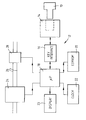
- The invention will now be described, by way of example only, with reference to the accompanying drawing, which is a simplified block diagram of a prepayment water metering system in accordance with the present invention.
- The prepayment water metering system shown in the drawing is intended for installation in a water consumer's premises, and is closely based on the system described in our United Kingdom Patent No. 2 191 622 (which was in turn a development of the system described in our United Kingdom Patent No. 2 153 573).
- Thus the system comprises a
key 10, known as a customer key, containing a non-volatile memory such as an EEPROM, and aprepayment unit 12 having areceptacle 14 for receiving thekey 10. The physical form of thekey 10 and thereceptacle 12 can be as described in our United Kingdom Patent No. 2 191 883. - Associated with the
receptacle 14, within theunit 12, is akey interface circuit 16 coupled to amicroprocessor 18. Themicroprocessor 18 is coupled in turn to anothernon-volatile memory 20 in the form of an EEPROM, to aclock 22 and to adisplay 23, all forming part of theunit 12. Themicroprocessor 18 is also coupled to aflow meter 24 connected in the mainwater inlet pipe 26 to the consumer's premises, and to a solenoid-operatedvalve 28 also connected in thepipe 26. Themeter 24 and thevalve 28 are preferably mounted in a common housing (not shown), and are connected to theunit 12 via an electrical cable. - The system operates substantially as described in our United Kingdom Patents Nos. 2 153 574 and 2 191 622. In particular, the consumer takes the
key 10 to a vending machine, typically located in or at a post office or other readily accessible premises, and inserts thekey 10 into a receptacle, similar to thereceptacle 14, in the machine. The consumer then inserts coins or bank notes into the machine, which, having read the key memory, responds by writing credit data representative of the amount of credit purchased into the key memory, along with tariff data representative of the current water supply tariff or tariffs and pass number data indicative of how many times the key has been used. The key memory typically already contains identification data uniquely identifying the key, the meter or prepayment unit with which it is to be used and the consumer, all of which identification data was entered when thekey 10 was first issued to the consumer. - Having charged the
key 10 with credit, the consumer returns home and inserts the key into thereceptacle 14. This causes themicroprocessor 18 to read the contents of the key memory, to perform checks to see if these contents indicate a valid key as described in United Kingdom Patent No. 2 153 173, and if they do, to write them into thememory 20. Themicroprocessor 18 also writes the current reading or readings of themeter 24, which are stored in thememory 20, along with the time and date to which the readings relate, into the key memory, substantially as described in United Kingdom Patent No 2 191 622. - One difference between the system of the present invention and the system of our earlier United Kingdom Patents Nos. 2 153 573 and 2 191 622 (aside from the storage of monetary credit and tariff information in the key memory rather than an amount of water purchased) lies in what happens when the credit entered into the
unit 12 is exhausted. - In systems so far manufactured and sold by the Applicant under the aforementioned patents, which systems have primarily been for use in connection with the supply of electricity, the supply of electricity is discontinued when the credit entered into the
unit 12 is exhausted (although an emergency supply facility, allowing access to a predetermined amount of electricity or providing a predetermined amount of credit, is always incorporated). However, where the commodity being supplied is water, a complete discontinuance of the supply could perhaps have adverse health implications. In the system shown in the drawing, therefore, a small by-pass conduit 30, capable of permitting a flow of about two litres per hour, is arranged in parallel with thevalve 28. This flow is sufficient to provide drinking water and to fill lavatory cisterns (albeit rather slowly), but is nevertheless sufficiently inconvenient as to provide a powerful incentive to the consumer to purchase fresh credit by way of thekey 10. - However, the main difference between the system of the present invention and those of our earlier patents lies in the programming of the
microprocessor 18. Thus themicroprocessor 18 is additionally programmed to periodically produce, in the period after the closure of thevalve 28 and before the insertion of akey 10 containing fresh credit (ie the period when the valve is closed or supposed to be closed), a pair of signals which respectively re-open and then substantially immediately re-close the valve, typically at predetermined time intervals. This tends to ensure that thevalve 28 does not become stuck in its closed state when that closed state would otherwise be of prolonged duration, eg more than seven days. - The
microprocessor 18 is further programmed to produce such a pair of signals in response to the production by themeter 24 of a predetermined number of flow pulses in a given time, indicating a predetermined non-zero flow, during the aforementioned period when thevalve 28 is closed or supposed to be closed, since such pulse production is an indication that the valve may have been fraudulently caused to re-open (ie without the insertion of akey 10 containing fresh credit). - The predetermined non-zero flow is selected to be just above the maximum flow which can pass through the by-pass conduit 30, since it will be appreciated that the by-pass flow is in fact metered by the
meter 24. Subsequently such pairs of signals are preferably produced by themicroprocessor 18 at predetermined time intervals rather than in response to the subsequent production by themeter 24 of another set of the predetermined number of flow pulses, since this enables the number of such pairs of signals to be kept to a predetermined, relatively low level, thus avoiding excessive power consumption where theunit 12 is battery powered (as is normally the case in a water metering context). - When the
microprocessor 18 detects the existence of the predetermined non-zero flow in the circumstances outlined above, it additionally produces and stores in the EEPROM 20 a signal indicating a possible fraud. - Finally, the
microprocessor 18 is also programmed such that, if thevalve 28 remains in its open state for more than seven days, the microprocessor sends a pair of signals which respectively close it and then substantially immediately re-open it, so reducing the possibility of the valve sticking in its open state. - Many modifications can be made to the described embodiment of the invention. For example, the by-pass conduit 30 can be replaced by a conduit formed in the body of the
valve 28, or even in the valve closure member of thevalve 28. Alternatively, the by-pass conduit 30 can by-pass themeter 24 as well as thevalve 28, in which case the predetermined non-zero flow which themicroprocessor 18 is programmed to detect can be lower, ie close to zero. In the limit, the by-pass conduit 30 can be omitted altogether, especially if a relatively long duration emergency facility is provided. - Additionally, the key 10 need not have the physical form of a key, but can instead be constituted for example by a so-called "smart card" or by a magnetic card. And finally, the water supply can be pre-paid for on a timed basis, rather than on a metered basis (ie a given amount of credit permits supply for say a week or a month). In this case, the metering function can still be retained, with the
clock 22 and themicroprocessor 18 serving additionally to provide the necessary timing function, and with the meter readings still being entered in thekey 10 along with time and date information. However, in the limit, the metering function can be omitted altogether, eg by omitting theflow meter 24. But even in this case, it may still be desired to store information generated in or by the consumer's part of the system in thekey 10, eg the aforementioned signal stored in the EEPROM 20 and indicating a possible fraud.
Claims (7)
- A prepayment water supply system comprising a prepayment token having a memory, and supply control means including an electrically-operable valve for controlling the supply of the water, a receptacle for receiving the token, and a circuit coupled to the receptacle and to the valve and responsive to credit data read from the token memory to close the valve when an amount of water or a time period determined by said credit data has been supplied or has elapsed, the circuit being operative during the period prior to the insertion of a token having fresh credit data in its memory into the receptacle (during which period the valve is closed or supposed to be closed) to send from time to time a pair of signals to respectively re-open and substantially immediately re-close the valve.
- A system as claimed in claim 1, wherein the pairs of signals are sent at predetermined time intervals so as to reduce the possibility of the valve becomibg stuck in its closed state when this closed state would otherwise last for a prolonged period.
- A system as claimed in claim 1 or claim 2, wherein the supply control means includes a metering unit for metering the water, and such a pair of signals is sent in response to the detection by the meter of a predetermined non-zero flow.
- A system as claimed in claim 3, wherein the circuit includes means for storing a signal representative of such detection as an indication of possible fraud.
- A system as claimed in claim 4, wherein subsequent such pairs of signals are sent at preselected time intervals if said flow continues to be detected.
- A prepayment water supply system comprising a prepayment token having a memory, and supply control means including an electrically-operable valve for controlling the supply of the water, a receptacle for receiving the token, and a circuit coupled to the receptacle and to the valve and responsive to credit data read from the token memory to close the valve when an amount of water or a time period determined by said credit data has been supplied or has elapsed, the circuit being operative when the valve has remained in one of its states for more than a given amount of time to send a pair of signals to respectively switch the valve to its other state and substantially immediately switch it back to said one state.
- A system as claimed in any preceding claim, wherein such a pair of signals is sent if the valve remains in one state for more than seven days.
Applications Claiming Priority (4)
| Application Number | Priority Date | Filing Date | Title |
|---|---|---|---|
| GB929213635A GB9213635D0 (en) | 1991-11-30 | 1992-06-26 | Prepayment water metering systems |
| GB9213635 | 1992-06-26 | ||
| GB9221137A GB2268302B (en) | 1992-06-26 | 1992-10-08 | Prepayment water supply systems |
| GB9221137 | 1992-10-08 |
Publications (2)
| Publication Number | Publication Date |
|---|---|
| EP0576276A1 true EP0576276A1 (en) | 1993-12-29 |
| EP0576276B1 EP0576276B1 (en) | 1997-03-12 |
Family
ID=26301135
Family Applications (1)
| Application Number | Title | Priority Date | Filing Date |
|---|---|---|---|
| EP93304918A Expired - Lifetime EP0576276B1 (en) | 1992-06-26 | 1993-06-23 | Prepayment water supply system |
Country Status (5)
| Country | Link |
|---|---|
| EP (1) | EP0576276B1 (en) |
| AT (1) | ATE150196T1 (en) |
| DE (1) | DE69308656T2 (en) |
| ES (1) | ES2101954T3 (en) |
| GR (1) | GR3023710T3 (en) |
Cited By (5)
| Publication number | Priority date | Publication date | Assignee | Title |
|---|---|---|---|---|
| WO1997010575A1 (en) * | 1995-09-14 | 1997-03-20 | Francisco Mathieu | Prepaid rated utility supply controller device |
| FR2746941A1 (en) * | 1996-03-29 | 1997-10-03 | Schneider Electric Sa | Energy pre-payment control system with automatic test facility |
| WO1999042963A1 (en) * | 1998-02-10 | 1999-08-26 | Whitehead, John, Anthony, Bailie | Apparatus for prepayment water management |
| WO2000036233A1 (en) * | 1998-12-13 | 2000-06-22 | Bermad | Water control device |
| US6950730B1 (en) * | 1999-11-12 | 2005-09-27 | Bouwhuis Egbert A J | System for certified use of electrical energy |
Citations (5)
| Publication number | Priority date | Publication date | Assignee | Title |
|---|---|---|---|---|
| GB2153573A (en) * | 1984-01-25 | 1985-08-21 | Schlumberger Electronics | A prepayment system |
| GB2191622A (en) * | 1986-06-16 | 1987-12-16 | Schlumberger Electronics | Commodity metering system |
| GB2191883A (en) * | 1986-06-16 | 1987-12-23 | Schlumberger Electronics | Electronic token |
| GB2208955A (en) * | 1987-08-19 | 1989-04-19 | Gen Electric Plc | Prepayment systems for supply of a commodity |
| FR2665504A1 (en) * | 1990-08-01 | 1992-02-07 | Tilhet Daniel | System for enabling the operation of a controlled element, especially of a solenoid valve for dispensing flushing water |
-
1993
- 1993-06-23 DE DE69308656T patent/DE69308656T2/en not_active Expired - Fee Related
- 1993-06-23 AT AT93304918T patent/ATE150196T1/en not_active IP Right Cessation
- 1993-06-23 ES ES93304918T patent/ES2101954T3/en not_active Expired - Lifetime
- 1993-06-23 EP EP93304918A patent/EP0576276B1/en not_active Expired - Lifetime
-
1997
- 1997-06-09 GR GR970401351T patent/GR3023710T3/en unknown
Patent Citations (5)
| Publication number | Priority date | Publication date | Assignee | Title |
|---|---|---|---|---|
| GB2153573A (en) * | 1984-01-25 | 1985-08-21 | Schlumberger Electronics | A prepayment system |
| GB2191622A (en) * | 1986-06-16 | 1987-12-16 | Schlumberger Electronics | Commodity metering system |
| GB2191883A (en) * | 1986-06-16 | 1987-12-23 | Schlumberger Electronics | Electronic token |
| GB2208955A (en) * | 1987-08-19 | 1989-04-19 | Gen Electric Plc | Prepayment systems for supply of a commodity |
| FR2665504A1 (en) * | 1990-08-01 | 1992-02-07 | Tilhet Daniel | System for enabling the operation of a controlled element, especially of a solenoid valve for dispensing flushing water |
Cited By (6)
| Publication number | Priority date | Publication date | Assignee | Title |
|---|---|---|---|---|
| WO1997010575A1 (en) * | 1995-09-14 | 1997-03-20 | Francisco Mathieu | Prepaid rated utility supply controller device |
| FR2746941A1 (en) * | 1996-03-29 | 1997-10-03 | Schneider Electric Sa | Energy pre-payment control system with automatic test facility |
| WO1999042963A1 (en) * | 1998-02-10 | 1999-08-26 | Whitehead, John, Anthony, Bailie | Apparatus for prepayment water management |
| WO2000036233A1 (en) * | 1998-12-13 | 2000-06-22 | Bermad | Water control device |
| US6701956B1 (en) | 1998-12-13 | 2004-03-09 | Bermad | Water control device |
| US6950730B1 (en) * | 1999-11-12 | 2005-09-27 | Bouwhuis Egbert A J | System for certified use of electrical energy |
Also Published As
| Publication number | Publication date |
|---|---|
| DE69308656D1 (en) | 1997-04-17 |
| ES2101954T3 (en) | 1997-07-16 |
| ATE150196T1 (en) | 1997-03-15 |
| GR3023710T3 (en) | 1997-09-30 |
| DE69308656T2 (en) | 1997-11-13 |
| EP0576276B1 (en) | 1997-03-12 |
Similar Documents
| Publication | Publication Date | Title |
|---|---|---|
| US4908769A (en) | Commodity metering systems | |
| US4240030A (en) | Intelligent electric utility meter | |
| US5734150A (en) | Electronic funds acceptor for vending machines | |
| US5003520A (en) | Time accounting system, in particular for parking subject to charge | |
| US4777354A (en) | System for controlling the supply of utility services to consumers | |
| IL98880A (en) | System for monitoring parked vehicles | |
| GB2208955A (en) | Prepayment systems for supply of a commodity | |
| EP0419106A1 (en) | Commodity metering systems | |
| EP0534803B1 (en) | Prepayment system | |
| EP0063893B1 (en) | Energy controller | |
| EP0545550B1 (en) | Prepayment water supply systems | |
| EP0576276B1 (en) | Prepayment water supply system | |
| EP0092436A2 (en) | Improved apparatus for the collection of payments for commodities | |
| EP0545549A1 (en) | Prepayment systems | |
| GB2312772A (en) | Prepayment commodity supply system | |
| WO1996003720A1 (en) | Apparatus for metering and dispensing a commodity | |
| EP0354975B1 (en) | Commodity meters | |
| GB2268302A (en) | Prepayment water supply systems | |
| GB2279516A (en) | Electricity supply control systems | |
| WO1993022743A1 (en) | Encoding of machine readable cards and secure systems | |
| JPH0755530A (en) | Liquid supplying device | |
| JPH06331410A (en) | Liquid supplying device | |
| JPH0565917B2 (en) | ||
| JPH0783697A (en) | Liquid supply system | |
| JPH02300889A (en) | Fare card system |
Legal Events
| Date | Code | Title | Description |
|---|---|---|---|
| PUAI | Public reference made under article 153(3) epc to a published international application that has entered the european phase |
Free format text: ORIGINAL CODE: 0009012 |
|
| AK | Designated contracting states |
Kind code of ref document: A1 Designated state(s): AT BE DE DK ES FR GR IE IT NL PT |
|
| 17P | Request for examination filed |
Effective date: 19940614 |
|
| 17Q | First examination report despatched |
Effective date: 19951212 |
|
| GRAG | Despatch of communication of intention to grant |
Free format text: ORIGINAL CODE: EPIDOS AGRA |
|
| GRAH | Despatch of communication of intention to grant a patent |
Free format text: ORIGINAL CODE: EPIDOS IGRA |
|
| GRAH | Despatch of communication of intention to grant a patent |
Free format text: ORIGINAL CODE: EPIDOS IGRA |
|
| GRAA | (expected) grant |
Free format text: ORIGINAL CODE: 0009210 |
|
| AK | Designated contracting states |
Kind code of ref document: B1 Designated state(s): AT BE DE DK ES FR GR IE IT NL PT |
|
| PG25 | Lapsed in a contracting state [announced via postgrant information from national office to epo] |
Ref country code: NL Free format text: LAPSE BECAUSE OF FAILURE TO SUBMIT A TRANSLATION OF THE DESCRIPTION OR TO PAY THE FEE WITHIN THE PRESCRIBED TIME-LIMIT Effective date: 19970312 Ref country code: DK Effective date: 19970312 Ref country code: BE Effective date: 19970312 Ref country code: AT Effective date: 19970312 |
|
| REF | Corresponds to: |
Ref document number: 150196 Country of ref document: AT Date of ref document: 19970315 Kind code of ref document: T |
|
| REF | Corresponds to: |
Ref document number: 69308656 Country of ref document: DE Date of ref document: 19970417 |
|
| ITF | It: translation for a ep patent filed |
Owner name: BARZANO' E ZANARDO MILANO S.P.A. |
|
| PG25 | Lapsed in a contracting state [announced via postgrant information from national office to epo] |
Ref country code: PT Effective date: 19970612 |
|
| REG | Reference to a national code |
Ref country code: ES Ref legal event code: FG2A Ref document number: 2101954 Country of ref document: ES Kind code of ref document: T3 |
|
| ET | Fr: translation filed | ||
| NLV1 | Nl: lapsed or annulled due to failure to fulfill the requirements of art. 29p and 29m of the patents act | ||
| REG | Reference to a national code |
Ref country code: GR Ref legal event code: FG4A Free format text: 3023710 |
|
| PLBE | No opposition filed within time limit |
Free format text: ORIGINAL CODE: 0009261 |
|
| STAA | Information on the status of an ep patent application or granted ep patent |
Free format text: STATUS: NO OPPOSITION FILED WITHIN TIME LIMIT |
|
| 26N | No opposition filed | ||
| PGFP | Annual fee paid to national office [announced via postgrant information from national office to epo] |
Ref country code: FR Payment date: 19990505 Year of fee payment: 7 |
|
| PGFP | Annual fee paid to national office [announced via postgrant information from national office to epo] |
Ref country code: DE Payment date: 19990803 Year of fee payment: 7 |
|
| PG25 | Lapsed in a contracting state [announced via postgrant information from national office to epo] |
Ref country code: FR Free format text: LAPSE BECAUSE OF NON-PAYMENT OF DUE FEES Effective date: 20010228 |
|
| REG | Reference to a national code |
Ref country code: FR Ref legal event code: ST |
|
| PG25 | Lapsed in a contracting state [announced via postgrant information from national office to epo] |
Ref country code: DE Free format text: LAPSE BECAUSE OF NON-PAYMENT OF DUE FEES Effective date: 20010403 |
|
| PGFP | Annual fee paid to national office [announced via postgrant information from national office to epo] |
Ref country code: IE Payment date: 20020625 Year of fee payment: 10 |
|
| REG | Reference to a national code |
Ref country code: FR Ref legal event code: GC |
|
| PG25 | Lapsed in a contracting state [announced via postgrant information from national office to epo] |
Ref country code: IE Free format text: LAPSE BECAUSE OF NON-PAYMENT OF DUE FEES Effective date: 20030623 |
|
| REG | Reference to a national code |
Ref country code: IE Ref legal event code: MM4A |
|
| REG | Reference to a national code |
Ref country code: FR Ref legal event code: DG |
|
| PGFP | Annual fee paid to national office [announced via postgrant information from national office to epo] |
Ref country code: GR Payment date: 20050524 Year of fee payment: 13 |
|
| PG25 | Lapsed in a contracting state [announced via postgrant information from national office to epo] |
Ref country code: IT Free format text: LAPSE BECAUSE OF NON-PAYMENT OF DUE FEES;WARNING: LAPSES OF ITALIAN PATENTS WITH EFFECTIVE DATE BEFORE 2007 MAY HAVE OCCURRED AT ANY TIME BEFORE 2007. THE CORRECT EFFECTIVE DATE MAY BE DIFFERENT FROM THE ONE RECORDED. Effective date: 20050623 |
|
| PGFP | Annual fee paid to national office [announced via postgrant information from national office to epo] |
Ref country code: ES Payment date: 20050728 Year of fee payment: 13 |
|
| PG25 | Lapsed in a contracting state [announced via postgrant information from national office to epo] |
Ref country code: ES Free format text: LAPSE BECAUSE OF NON-PAYMENT OF DUE FEES Effective date: 20060624 |
|
| REG | Reference to a national code |
Ref country code: ES Ref legal event code: FD2A Effective date: 20060624 |
|
| PG25 | Lapsed in a contracting state [announced via postgrant information from national office to epo] |
Ref country code: GR Free format text: LAPSE BECAUSE OF NON-PAYMENT OF DUE FEES Effective date: 20070104 |