EP0575678B1 - Medium-earth-altitude satellite-based cellular telecommunications system - Google Patents
Medium-earth-altitude satellite-based cellular telecommunications system Download PDFInfo
- Publication number
- EP0575678B1 EP0575678B1 EP92308604A EP92308604A EP0575678B1 EP 0575678 B1 EP0575678 B1 EP 0575678B1 EP 92308604 A EP92308604 A EP 92308604A EP 92308604 A EP92308604 A EP 92308604A EP 0575678 B1 EP0575678 B1 EP 0575678B1
- Authority
- EP
- European Patent Office
- Prior art keywords
- satellite
- satellites
- telecommunications system
- coverage
- cellular telecommunications
- Prior art date
- Legal status (The legal status is an assumption and is not a legal conclusion. Google has not performed a legal analysis and makes no representation as to the accuracy of the status listed.)
- Revoked
Links
- 230000001413 cellular effect Effects 0.000 title claims description 50
- 239000002131 composite material Substances 0.000 claims description 4
- 230000001934 delay Effects 0.000 claims description 2
- 230000001174 ascending effect Effects 0.000 description 3
- 230000007704 transition Effects 0.000 description 3
- 230000005855 radiation Effects 0.000 description 2
- 230000006978 adaptation Effects 0.000 description 1
- 230000005540 biological transmission Effects 0.000 description 1
- 238000009434 installation Methods 0.000 description 1
- 238000012986 modification Methods 0.000 description 1
- 230000004048 modification Effects 0.000 description 1
Images

Classifications
-
- H—ELECTRICITY
- H04—ELECTRIC COMMUNICATION TECHNIQUE
- H04B—TRANSMISSION
- H04B7/00—Radio transmission systems, i.e. using radiation field
- H04B7/14—Relay systems
- H04B7/15—Active relay systems
- H04B7/185—Space-based or airborne stations; Stations for satellite systems
- H04B7/195—Non-synchronous stations
-
- B—PERFORMING OPERATIONS; TRANSPORTING
- B64—AIRCRAFT; AVIATION; COSMONAUTICS
- B64G—COSMONAUTICS; VEHICLES OR EQUIPMENT THEREFOR
- B64G1/00—Cosmonautic vehicles
- B64G1/10—Artificial satellites; Systems of such satellites; Interplanetary vehicles
- B64G1/1007—Communications satellites
-
- B—PERFORMING OPERATIONS; TRANSPORTING
- B64—AIRCRAFT; AVIATION; COSMONAUTICS
- B64G—COSMONAUTICS; VEHICLES OR EQUIPMENT THEREFOR
- B64G1/00—Cosmonautic vehicles
- B64G1/10—Artificial satellites; Systems of such satellites; Interplanetary vehicles
- B64G1/1085—Swarms and constellations
-
- B—PERFORMING OPERATIONS; TRANSPORTING
- B64—AIRCRAFT; AVIATION; COSMONAUTICS
- B64G—COSMONAUTICS; VEHICLES OR EQUIPMENT THEREFOR
- B64G1/00—Cosmonautic vehicles
- B64G1/22—Parts of, or equipment specially adapted for fitting in or to, cosmonautic vehicles
- B64G1/24—Guiding or controlling apparatus, e.g. for attitude control
- B64G1/242—Orbits and trajectories
Definitions
- This invention relates generally to cellular telecommunications systems and, more particularly, to satellite-based cellular telecommunications systems comprising the features of the pre-charactizing portion of claim 1.
- Such a system is disclosed in the Application of TRW Inc. to the Federal Communications Commission of the USA for authority to construct a communications satellite system "Odyssey (SM)" dated May 31, 1991.
- SM communications satellite system
- a typical cellular telephone systems includes a grid of service zones or cells, with each cell having a base station situated near its center. A mobile telephone user located in a particular cell is connected to that cell's base station through low-power radio frequency (rf) transmissions. Each base station is connected by trunk lines to a gateway station, which is connected by trunk lines to a local and long distance telephone network.
- rf radio frequency
- the cellular telecommunications systems in use today are generally land-based systems that have been installed in large metropolitan areas. Small towns and rural areas cannot economically justify the installation and operation of one of these relatively costly systems.
- satellite-based cellular telecommunications systems have been proposed which would provide world-wide cellular telephone service.
- These proposed cellular telephone systems typically include a large constellation of telecommunications satellites in low earth orbit at an altitude of between approximately 740 and 1850 km (400 and 1000 nautical miles), which is just below the Van Allen radiation belt. At these low altitudes, as many as 50 to 80 satellites are required to provide adequate coverage of the entire earth.
- AIAA 92-2060 "Odyssey, A Constellation For Personal Communications" by Roger J. Rusch et al, 14th AIAA International Communication Satellite Systems Conference & Exhibit, March 22-26 1992 Washington, DC, discloses on page 4, left col. first para., that at any time most of the satellites provide primary service to these regions. Additional satellites are used for the transition before a satellite moves on to the next assigned region. Traffic builds up on the approaching satellite while traffic wanes on the receding satellite.
- the problem underlying the present invention is the reduction of the likelihood of dropouts.
- the present invention includes several features which essentially eliminate beam-to-beam and satellite-to-satellite handovers, thus dramatically reducing the likelihood of dropouts.
- One of these important features is an assignment of each satellite to a sequence of fixed service regions (rather than a continuously varying coverage area) during each satellite's orbit. The boresight of the satellite's antennas remains centered on a given assigned service region during the entire time the service region is visible to the satellite. This results in an essentially fixed beam pattern thus practically eliminating beam-to-beam handovers.
- Another one of these important features is a provision for overlap in the coverage of each service region by two successive satellites during the transition in service from one satellite to another. All calls that are placed during the overlap interval are assigned to the arriving satellite. Therefore, only calls placed prior to the overlap interval and extending beyond the overlap interval are subjected to satellite-to-satellite handovers when the departing satellite is reoriented to its new service region.
- a constellation of nine satellites provides complete global coverage of the earth by at least one satellite at all times with a minimum elevation angle of 10°.
- the constellation includes three inclined circular orbital planes which are evenly spaced about the earth with ascending nodes at 120° intervals about the equator. Three satellites are placed in each orbit and evenly spaced at 120° intervals at an altitude of 10360 km (5600 nautical miles). Each orbital plane is inclined at an angle of 55° relative to the equatorial plane.
- a constellation of twelve satellites provides global coverage of the earth by at least two satellites at all times with a minimum elevation angle of 10°.
- the constellation includes three inclined circular orbital planes with the same characteristics as the nine satellite constellation, except that four satellites are placed in each orbit, evenly spaced at 90° intervals.
- the present invention is embodied in a satellite-based cellular telecommunications system employing a constellation of telecommunications satellites in medium earth orbit to provide multibeam radio frequency (rf) communications links for world-wide cellular telephone service with a minimum number of satellites.
- the telecommunications satellites are placed in a plurality of inclined orbits about the earth at an altitude of between approximately 10360 km and 18500 km (5600 and 10,000 nautical miles).
- the characteristics of the orbits are tailored to maximize the coverage area of the satellites and their related line-of-sight elevation angles, while minimizing propagation time delays, the number of beam-to-beam and satellite-to-satellite handovers, and the total number of satellites.
- the present invention also includes several additional features which essentially eliminate beam-to-beam and satellite-to-satellite handovers, thus dramatically reducing the likelihood of dropouts.
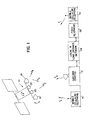
- FIG. 1 illustrates a satellite-based cellular telecommunications system in accordance with the present invention.
- the cellular telecommunications system includes a constellation of telecommunications satellites 10 in medium earth orbit, a gateway station 12 situated in each region serviced by the satellites and a plurality of mobile cellular telephones 14 located in the service region of the satellite 10.
- the mobile cellular telephones 14 can also include mobile facsimile machines and modem-equipped computers.
- the telecommunications satellite 10 provides a multibeam rf communications link with the mobile cellular telephones 14 using two multibeam antennas 16, 18 and an rf communications link with the gateway station 12 using two antennas 20, 22.
- Multibeam antenna 16 receives rf signals from the mobile cellular telephones 14 on frequency band F 1 .
- the satellite 10 then amplifies, translates and transmits the rf signals down to the gateway station 12 on frequency band F 2 using antenna 20.
- the gateway station 12 is connected by trunk lines to a local and long distance telephone network 24, which provides connections to a fixed telephone 26.
- Rf signals are transmitted from the gateway station 12 back to the telecommunications satellite 10 on frequency band F 3 and received using antenna 22.
- the satellite 10 then amplifies, translates and transmits the rf signals back down to the mobile cellular telephones 14 on frequency band F 4 using multibeam antenna 18.
- a mobile telephone user can communicate with another mobile telephone user in the same service region of the satellite 10 or in the service region of another satellite 10, or with a fixed telephone user located anywhere in the world. If in communication with another mobile telephone user in the same service region, the rf signals are transmitted up from the mobile cellular telephone 14 to the satellite 10, then down to the gateway station 12, then back up to the satellite 10, and then down to the other mobile cellular telephone 14, and vice verse.
- This type of connection requires a double hop, which doubles the propagation time delay.
- the rf signals are transmitted up from the mobile cellular telephone 14 to the satellite 10, then down to the gateway station 12, then through the local and long distance network 24, as necessary, to the gateway station 12 responsible for the other service region, then up to the satellite 10 responsible for the other service region, and then down to the other mobile cellular telephone 14, and vice verse.
- This type of connection also requires a double hop.
- the rf signals are transmitted up from the mobile cellular telephone 14 to the satellite 10, then down to the gateway station 12, and then through the local and long distance network 24, as necessary, to the fixed telephone 26, and vice verse. This type of connection requires only a single hop.
- the satellite 10 performs the function of the gateway station 12 for communications between mobile telephone users located in the same service region, thus requiring only a single hop.
- the rf signals are transmitted up from the mobile cellular telephone 14 to the satellite 10, the satellite 10 then performs signal processing on the rf signals to provide any necessary switching between the multiple beams, and then the rf signals are transmitted back down to the other mobile cellular telephone 14, and vice verse.
- the propagation time delay depends on the altitude of the telecommunications satellite 10 and the location of the mobile cellular telephones 14 in the service region.
- the time delay from the satellite 10 to the ground and vice verse is limited to 60 msec. Therefore, the single hop time delay is limited to 120 msec.
- the one hop time delay between two mobile cellular telephones 14 located directly below the satellite 10 is 69 msec., while the one hop time delay between two mobile cellular telephones 14 spaced apart at the minimum elevation angle of 10° is 96 msec.
- the relationship between station to station propagation time and satellite altitude for a single hop from a station on the ground up to the satellite and back down to the station at maximum range, which occurs when the satellite is at a minimum elevation of 10°, may be shown as follows: Satellite Altitude Maximum Station to Satellite Propagation Range Maximum Station to Station Propagation Time km (nmi) km (nmi) msec. 10175 (5500) 14163 (7656) 91 11100 (6000) 15153 (8191) 101 12025 (6500) 16139 (8724) 108 12950 (7000) 17122 (9255) 115 13875 (7500) 18096 (9782) 121
- the mobile cellular telephones 14 and the gateway station 12 are within view of the satellite 10 at all times at an elevation angle of at least 10°. As the satellite 10 moves out of view of the mobile cellular telephones 14 in a particular service region, another satellite 10 from the constellation comes into view. Each satellite 10 has a relatively narrow antenna footprint that is considerably smaller than the total area of visibility of the satellite. This is because it is 5 not practical to serve the entire area of visibility due to power and complexity constraints.
- the service region actually covered by the satellite 10 is determined by the composite coverage of the multibeam antennas 16, 18 has 19 beams for a composite footprint coverage of about 23°.
- Another ring of feeds can be added to the multibeam antenna to provide 37 beams for a composite footprint coverage of about 35°.
- Each beam has field of view (FOV) of about 5° and is capable of operating with a 1/2 W mobile cellular telephone 14 having an omnidirectional antenna.
- FOV field of view
- the present invention also includes several additional features which essentially eliminate beam-to-beam and satellite-to-satellite handovers, thus dramatically reducing the likelihood of dropouts.
- One of these important features is an assignment of each satellite to a sequence of fixed service regions during each satellite's orbit.
- the boresight of the satellite's antennas 16, 18 remains centered on the assigned service region is visible to the satellite with respect to antennas 20, 22 they are gimballed to point to the appropriate gateway station.
- the resulting nearly-fixed antenna beam pattern practically eliminates beam-to-beam handovers.
- the antenna boresight remains centered on the service region either by adjusting the attitude of the spacecraft 10 or by rotating gimballed antennas.
- Another one of the important features of the present invention is a provision for overlap in the coverage of each service region by two successive satellites during the transition in service from one satellite to another. All calls that are placed during the overlap interval are assigned to the arriving satellite. Therefore, only calls placed prior to the overlap interval and extending beyond the overlap interval are subjected to satellite-to-satellite handovers when the departing satellite is reoriented to its new service region.
- the constellation of telecommunications satellites 10 has three inclined orbital planes which are evenly spaced about the earth with ascending nodes at 120° intervals about the equator.
- the satellites 10 are placed in medium earth orbit at an altitude of between 10360 km and 18500 km (5600 and 10,000 nautical miles). This range of altitudes is above the Van Allen radiation belt, but substantially below the altitude for geosynchronous orbit. This provides good visibility with a minimum number of satellites without excessive power requirements.
- At least one of the telecommunications satellites 10 is visible at all times from each mobile cellular telephone 14 and gateway station 12 at an elevation angle of at least 10° to prevent shadowing.
- Figure 2 shows a constellation of nine satellites which provides global coverage of the earth by at least one satellite 10 at all times with a minimum elevation angle of 10°.
- the nine satellites are arranged in three circular orbital planes P 1 , P 2 , P 3 , with three satellites 30a-30c located in orbital plane P 1 , three satellites 32a-32c located in orbital plane P 2 and three satellites 34a-34c located in orbital plane P 3 .
- the satellites are evenly spaced at 120° intervals in each orbital plane at an altitude of 10360 km [5600 nautical miles].
- Each orbital plane is inclined at an angle of 55° relative to the equatorial plane.
- the relative phase angles between the satellites in different orbital planes is 80°. Therefore, before one satellite in the constellation disappears from a user's view, at least one additional satellite comes into view above an elevation angle of 10°.
- Figure 3 shows a constellation of twelve satellites which provides global coverage of the earth by at least two satellites at all times with a minimum elevation angle of 10°.
- the twelve satellites are arranged in the three circular orbital planes P 1 , P 2 , P 3 , with four satellites 30a-30d located in orbital plane P 1 , four satellites 32a-32d located in orbital plane P 2 and four satellites 34a-34d located in orbital plane P 3 .
- the satellites are evenly spaced at 90° intervals in each orbital plane at an altitude of 10360 km (5600 nautical miles).
- Each orbital plane is inclined at an angle of 55° relative to the equatorial plane.
- the relative phase angles between satellites in different orbital planes is 90°.
- the constellations providing single satellite coverage can be initially formed and then the coverage expanded later to provide double coverage by the addition of only three satellites. Conversely, the constellations providing double coverage allow for the failure of one satellite in each orbital plane without the loss of full service. The position of the remaining satellites in the orbital plane can be adjusted to provide single coverage until the satellite is repaired or replaced.
Landscapes
- Engineering & Computer Science (AREA)
- Remote Sensing (AREA)
- Aviation & Aerospace Engineering (AREA)
- Physics & Mathematics (AREA)
- Astronomy & Astrophysics (AREA)
- General Physics & Mathematics (AREA)
- Computer Networks & Wireless Communication (AREA)
- Signal Processing (AREA)
- Chemical & Material Sciences (AREA)
- Combustion & Propulsion (AREA)
- Radar, Positioning & Navigation (AREA)
- Radio Relay Systems (AREA)
- Mobile Radio Communication Systems (AREA)
Description
- This invention relates generally to cellular telecommunications systems and, more particularly, to satellite-based cellular telecommunications systems comprising the features of the pre-charactizing portion of claim 1. Such a system is disclosed in the Application of TRW Inc. to the Federal Communications Commission of the USA for authority to construct a communications satellite system "Odyssey (SM)" dated May 31, 1991.
- The use of mobile cellular telephones has proliferated in the many large metropolitan areas in which cellular telecommunications systems have been installed. Cellular telecommunications systems provide voice communications between a mobile telephone user and fixed telephone users or to other mobile telephone users, as well as data communications for mobile facsimile machines and modem-equipped computers. A typical cellular telephone systems includes a grid of service zones or cells, with each cell having a base station situated near its center. A mobile telephone user located in a particular cell is connected to that cell's base station through low-power radio frequency (rf) transmissions. Each base station is connected by trunk lines to a gateway station, which is connected by trunk lines to a local and long distance telephone network.
- The cellular telecommunications systems in use today are generally land-based systems that have been installed in large metropolitan areas. Small towns and rural areas cannot economically justify the installation and operation of one of these relatively costly systems. To provide cellular telephone service for these areas, satellite-based cellular telecommunications systems have been proposed which would provide world-wide cellular telephone service. These proposed cellular telephone systems typically include a large constellation of telecommunications satellites in low earth orbit at an altitude of between approximately 740 and 1850 km (400 and 1000 nautical miles), which is just below the Van Allen radiation belt. At these low altitudes, as many as 50 to 80 satellites are required to provide adequate coverage of the entire earth. This results in an extremely costly and complex system with a large number of rapidly changing crosslinks and a large number of beam-to-beam and satellite-to-satellite handovers. Accordingly, there has been a need for a less costly and complex satellite-based cellular telecommunications system. The present invention clearly fulfils this need.
- AIAA 92-2060 "Odyssey, A Constellation For Personal Communications" by Roger J. Rusch et al, 14th AIAA International Communication Satellite Systems Conference & Exhibit, March 22-26 1992 Washington, DC, discloses on page 4, left col. first para., that at any time most of the satellites provide primary service to these regions. Additional satellites are used for the transition before a satellite moves on to the next assigned region. Traffic builds up on the approaching satellite while traffic wanes on the receding satellite.
- On page 5, left col. third para., it is mentioned that, in making a circuit request, a user terminal transmits requests to overhead satellites. The user will be assigned to the beam that provides the strongest signal to the base station.
- The problem underlying the present invention is the reduction of the likelihood of dropouts.
- To solve this problem, the above described system is further characterized by the features of the characterizing portion of claim 1.
- The present invention includes several features which essentially eliminate beam-to-beam and satellite-to-satellite handovers, thus dramatically reducing the likelihood of dropouts. One of these important features is an assignment of each satellite to a sequence of fixed service regions (rather than a continuously varying coverage area) during each satellite's orbit. The boresight of the satellite's antennas remains centered on a given assigned service region during the entire time the service region is visible to the satellite. This results in an essentially fixed beam pattern thus practically eliminating beam-to-beam handovers. Another one of these important features is a provision for overlap in the coverage of each service region by two successive satellites during the transition in service from one satellite to another. All calls that are placed during the overlap interval are assigned to the arriving satellite. Therefore, only calls placed prior to the overlap interval and extending beyond the overlap interval are subjected to satellite-to-satellite handovers when the departing satellite is reoriented to its new service region.
- In one preferred embodiment of the present invention, a constellation of nine satellites provides complete global coverage of the earth by at least one satellite at all times with a minimum elevation angle of 10°. The constellation includes three inclined circular orbital planes which are evenly spaced about the earth with ascending nodes at 120° intervals about the equator. Three satellites are placed in each orbit and evenly spaced at 120° intervals at an altitude of 10360 km (5600 nautical miles). Each orbital plane is inclined at an angle of 55° relative to the equatorial plane. In another preferred embodiment of the invention, a constellation of twelve satellites provides global coverage of the earth by at least two satellites at all times with a minimum elevation angle of 10°. The constellation includes three inclined circular orbital planes with the same characteristics as the nine satellite constellation, except that four satellites are placed in each orbit, evenly spaced at 90° intervals.
- It will be appreciated from the foregoing that the present invention represents a significant advance in the field of satellite-based cellular telecommunications systems. Other features and advantages of the present invention will become apparent from the following more detailed description, taken in conjunction with the accompanying drawings, which illustrate, by way of example, the principles of the invention.
-
- Figure 1 is a schematic illustration of a satellite-based cellular telecommunications system in accordance with the present invention;
- Figure 2 is a schematic illustration of a constellation of telecommunication satellites providing single global coverage of the earth; and
- Figure 3 is a schematic illustration of a constellation of telecommunication satellites providing double global coverage of the earth.
- As shown in the drawings for purposes of illustration, the present invention is embodied in a satellite-based cellular telecommunications system employing a constellation of telecommunications satellites in medium earth orbit to provide multibeam radio frequency (rf) communications links for world-wide cellular telephone service with a minimum number of satellites. The telecommunications satellites are placed in a plurality of inclined orbits about the earth at an altitude of between approximately 10360 km and 18500 km (5600 and 10,000 nautical miles). The characteristics of the orbits, including the number of orbits, the inclination of each orbit, the number of satellites in each orbit and the altitude of the satellites, are tailored to maximize the coverage area of the satellites and their related line-of-sight elevation angles, while minimizing propagation time delays, the number of beam-to-beam and satellite-to-satellite handovers, and the total number of satellites. The present invention also includes several additional features which essentially eliminate beam-to-beam and satellite-to-satellite handovers, thus dramatically reducing the likelihood of dropouts.
- Figure 1 illustrates a satellite-based cellular telecommunications system in accordance with the present invention. The cellular telecommunications system includes a constellation of
telecommunications satellites 10 in medium earth orbit, a gateway station 12 situated in each region serviced by the satellites and a plurality of mobilecellular telephones 14 located in the service region of thesatellite 10. The mobilecellular telephones 14 can also include mobile facsimile machines and modem-equipped computers. Thetelecommunications satellite 10 provides a multibeam rf communications link with the mobilecellular telephones 14 using twomultibeam antennas antennas Multibeam antenna 16 receives rf signals from the mobilecellular telephones 14 on frequency band F1. Thesatellite 10 then amplifies, translates and transmits the rf signals down to the gateway station 12 on frequency band F2 using antenna 20. The gateway station 12 is connected by trunk lines to a local and longdistance telephone network 24, which provides connections to a fixedtelephone 26. Rf signals are transmitted from the gateway station 12 back to thetelecommunications satellite 10 on frequency band F3 and received usingantenna 22. Thesatellite 10 then amplifies, translates and transmits the rf signals back down to the mobilecellular telephones 14 on frequency band F4 usingmultibeam antenna 18. - Various types of connections are possible between the different users of the cellular telecommunications system of the present invention. A mobile telephone user can communicate with another mobile telephone user in the same service region of the
satellite 10 or in the service region of anothersatellite 10, or with a fixed telephone user located anywhere in the world. If in communication with another mobile telephone user in the same service region, the rf signals are transmitted up from the mobilecellular telephone 14 to thesatellite 10, then down to the gateway station 12, then back up to thesatellite 10, and then down to the other mobilecellular telephone 14, and vice verse. This type of connection requires a double hop, which doubles the propagation time delay. If in communication with another mobile telephone user in a different service region, the rf signals are transmitted up from the mobilecellular telephone 14 to thesatellite 10, then down to the gateway station 12, then through the local andlong distance network 24, as necessary, to the gateway station 12 responsible for the other service region, then up to thesatellite 10 responsible for the other service region, and then down to the other mobilecellular telephone 14, and vice verse. This type of connection also requires a double hop. If in communication with a fixed telephone user, the rf signals are transmitted up from the mobilecellular telephone 14 to thesatellite 10, then down to the gateway station 12, and then through the local andlong distance network 24, as necessary, to the fixedtelephone 26, and vice verse. This type of connection requires only a single hop. - In an alternative embodiment of the present invention, the
satellite 10 performs the function of the gateway station 12 for communications between mobile telephone users located in the same service region, thus requiring only a single hop. In this type of connection, the rf signals are transmitted up from the mobilecellular telephone 14 to thesatellite 10, thesatellite 10 then performs signal processing on the rf signals to provide any necessary switching between the multiple beams, and then the rf signals are transmitted back down to the other mobilecellular telephone 14, and vice verse. - The propagation time delay depends on the altitude of the
telecommunications satellite 10 and the location of the mobilecellular telephones 14 in the service region. In the present invention, at an altitude of between 10360 km and 18500 km (5600 and 10,000 nautical miles), the time delay from thesatellite 10 to the ground and vice verse is limited to 60 msec. Therefore, the single hop time delay is limited to 120 msec. At an altitude of 10360 km (5600 nautical miles), the one hop time delay between two mobilecellular telephones 14 located directly below thesatellite 10 is 69 msec., while the one hop time delay between two mobilecellular telephones 14 spaced apart at the minimum elevation angle of 10° is 96 msec. - The relationship between station to station propagation time and satellite altitude for a single hop from a station on the ground up to the satellite and back down to the station at maximum range, which occurs when the satellite is at a minimum elevation of 10°, may be shown as follows:
Satellite Altitude Maximum Station to Satellite Propagation Range Maximum Station to Station Propagation Time km (nmi) km (nmi) msec. 10175 (5500) 14163 (7656) 91 11100 (6000) 15153 (8191) 101 12025 (6500) 16139 (8724) 108 12950 (7000) 17122 (9255) 115 13875 (7500) 18096 (9782) 121 - The mobile
cellular telephones 14 and the gateway station 12 are within view of thesatellite 10 at all times at an elevation angle of at least 10°. As thesatellite 10 moves out of view of the mobilecellular telephones 14 in a particular service region, anothersatellite 10 from the constellation comes into view. Eachsatellite 10 has a relatively narrow antenna footprint that is considerably smaller than the total area of visibility of the satellite. This is because it is 5 not practical to serve the entire area of visibility due to power and complexity constraints. - The service region actually covered by the
satellite 10 is determined by the composite coverage of themultibeam antennas cellular telephone 14 having an omnidirectional antenna. - The present invention also includes several additional features which essentially eliminate beam-to-beam and satellite-to-satellite handovers, thus dramatically reducing the likelihood of dropouts. One of these important features is an assignment of each satellite to a sequence of fixed service regions during each satellite's orbit. The boresight of the satellite's
antennas antennas spacecraft 10 or by rotating gimballed antennas. - Another one of the important features of the present invention is a provision for overlap in the coverage of each service region by two successive satellites during the transition in service from one satellite to another. All calls that are placed during the overlap interval are assigned to the arriving satellite. Therefore, only calls placed prior to the overlap interval and extending beyond the overlap interval are subjected to satellite-to-satellite handovers when the departing satellite is reoriented to its new service region.
- In the preferred embodiments of the present invention, the constellation of
telecommunications satellites 10 has three inclined orbital planes which are evenly spaced about the earth with ascending nodes at 120° intervals about the equator. Thesatellites 10 are placed in medium earth orbit at an altitude of between 10360 km and 18500 km (5600 and 10,000 nautical miles). This range of altitudes is above the Van Allen radiation belt, but substantially below the altitude for geosynchronous orbit. This provides good visibility with a minimum number of satellites without excessive power requirements. At least one of thetelecommunications satellites 10 is visible at all times from each mobilecellular telephone 14 and gateway station 12 at an elevation angle of at least 10° to prevent shadowing. - Figure 2 shows a constellation of nine satellites which provides global coverage of the earth by at least one
satellite 10 at all times with a minimum elevation angle of 10°. The nine satellites are arranged in three circular orbital planes P1, P2, P3, with threesatellites 30a-30c located in orbital plane P1, threesatellites 32a-32c located in orbital plane P2 and three satellites 34a-34c located in orbital plane P3. The satellites are evenly spaced at 120° intervals in each orbital plane at an altitude of 10360 km [5600 nautical miles]. Each orbital plane is inclined at an angle of 55° relative to the equatorial plane. The relative phase angles between the satellites in different orbital planes is 80°. Therefore, before one satellite in the constellation disappears from a user's view, at least one additional satellite comes into view above an elevation angle of 10°. - Figure 3 shows a constellation of twelve satellites which provides global coverage of the earth by at least two satellites at all times with a minimum elevation angle of 10°. The twelve satellites are arranged in the three circular orbital planes P1, P2, P3, with four
satellites 30a-30d located in orbital plane P1, foursatellites 32a-32d located in orbital plane P2 and four satellites 34a-34d located in orbital plane P3. The satellites are evenly spaced at 90° intervals in each orbital plane at an altitude of 10360 km (5600 nautical miles). Each orbital plane is inclined at an angle of 55° relative to the equatorial plane. The relative phase angles between satellites in different orbital planes is 90°.Coverage Global Single Double Number of Satellites 9 12 Number Orbital Planes 3 3 Satellites per Plane 3 4 Apogee Altitude (nm) 5600 5600 Perigee Altitude (nm) 5600 5600 Inclination Angle 55° 55° Ascending Node Spacing 120° 120° Argument of Perigee 0° 0° Relative Phase Angle 80° 90° Minimum Elevation Angle 10° 10° - The constellations providing single satellite coverage can be initially formed and then the coverage expanded later to provide double coverage by the addition of only three satellites. Conversely, the constellations providing double coverage allow for the failure of one satellite in each orbital plane without the loss of full service. The position of the remaining satellites in the orbital plane can be adjusted to provide single coverage until the satellite is repaired or replaced.
- From the foregoing, it will be appreciated that the present invention represents a significant advance in the field of satellite-based cellular telecommunications systems. Although several preferred embodiments of the invention have been shown and described, it will be apparent that other adaptations and modifications can be made without departing from the scope of the invention. Accordingly, the invention is not to be limited, except as by the following claims.
Claims (6)
- A satellite-based cellular telecommunications system comprising:- at least one hand held mobile cellular telephone station (14) having an omnidirectional antenna for transceiving RF;- at least one gateway station (12);- said mobile cellular telephone station (14) and said gateway station (12) being spaced from one another within a predetermined region of the earth;- satellite constellation means (P1, P2, P3; 30a-30c, 32a-32c, 34a-34c) located in space over the earth for providing an RF frequency (rf) translation communication link with said mobile cellular telephone station (14) and said gateway station (12);- said satellite constellation means comprising a plurality of telecommunications satellites (30a-30c, 32a-32c, 34a-34c),- each of said satellites (30a-30c, 32a-32c, 34a-34c) including RF transceiving means having multiple RF output beams (16, 18), whereby a communications path may be established between said mobile cellular telephone station (14) and said gateway station (12);- said satellites (30a-30c, 32a-32c, 34a-34c) being spaced and moving in a plurality of orbits (P1, P2, P3) inclined at a predetermined angle relative to the equatorial plane of the earth at an altitude of between approximately 10360 km (5600 nmi) and 18500 km (10000 nmi);- wherein the characteristics of these orbits (P1, P2, P3), includingthe number of orbits (P1, P2, P3),the inclination of each orbit (P1, P2, P3),the number of satellites (30a-30c, 32a-32c, 34a-34c) in each orbit (P1, P2, P3) andthe altitude of the satellites (30a-30c, 32a-32c, 34a-34c) are tailored to maximize the coverage area of the satellites (30a-30c, 32a-32c, 34a-34c) and their related line-of-sight elevation angles, while minimizing
propagation time delays,the number of beam-to-beam and satellite-to-satellite handovers and the number of satellites (30a-30c, 32a-32c, 34a-34c); and- wherein the number of beam-to-beam handovers is further reduced by assigning each satellite a fixed service region and maintaining the antenna boresight of the satellite centered on said service region during the time the service region is visible to the satellite; and- wherein a portion of a coverage portion of a departing satellite overlaps a portion of a coverage portion of an arriving satellite, characterized in that all calls placed to or from a user located within the coverage overlap region are assigned to said arriving satellite. - The satellite-based cellular telecommunications system as set forth in claim 1, wherein the attitude of the satellites (30a-30c, 32a-32c, 34a-34c) is adjusted to maintain the antenna boresight centered on the service region.
- The satellite-based cellular telecommunications system as set forth in claim 1, wherein the antenna (16, 18) is gimballed and the antenna is rotated to maintain the antenna boresight centered on the service region.
- The satellite-based cellular telecommunications system as set forth in claim 1, wherein the orbits (P1, P2, P3) are approximately circular.
- The satellite-based cellular telecommunications system as set forth in claim 1, wherein the elevation angles are always at least 10°.
- The satellite-based cellular telecommunications system according to claim 1, wherein the transceiving means having multiple RF output beams for a composite foot print coverage of about 35°.
Priority Applications (2)
| Application Number | Priority Date | Filing Date | Title |
|---|---|---|---|
| DE9218851U DE9218851U1 (en) | 1992-05-28 | 1992-09-22 | Satellite-based cellular telecommunications system for medium earth orbits |
| EP96115571A EP0752762A3 (en) | 1992-05-28 | 1992-09-22 | Medium-earth-altitude satellite-based cellular telecommunications system |
Applications Claiming Priority (2)
| Application Number | Priority Date | Filing Date | Title |
|---|---|---|---|
| US89051092A | 1992-05-28 | 1992-05-28 | |
| US890510 | 1992-05-28 |
Related Child Applications (2)
| Application Number | Title | Priority Date | Filing Date |
|---|---|---|---|
| EP96115571A Division EP0752762A3 (en) | 1992-05-28 | 1992-09-22 | Medium-earth-altitude satellite-based cellular telecommunications system |
| EP96115571.0 Division-Into | 1992-09-22 |
Publications (2)
| Publication Number | Publication Date |
|---|---|
| EP0575678A1 EP0575678A1 (en) | 1993-12-29 |
| EP0575678B1 true EP0575678B1 (en) | 1997-01-08 |
Family
ID=25396777
Family Applications (2)
| Application Number | Title | Priority Date | Filing Date |
|---|---|---|---|
| EP96115571A Ceased EP0752762A3 (en) | 1992-05-28 | 1992-09-22 | Medium-earth-altitude satellite-based cellular telecommunications system |
| EP92308604A Revoked EP0575678B1 (en) | 1992-05-28 | 1992-09-22 | Medium-earth-altitude satellite-based cellular telecommunications system |
Family Applications Before (1)
| Application Number | Title | Priority Date | Filing Date |
|---|---|---|---|
| EP96115571A Ceased EP0752762A3 (en) | 1992-05-28 | 1992-09-22 | Medium-earth-altitude satellite-based cellular telecommunications system |
Country Status (3)
| Country | Link |
|---|---|
| EP (2) | EP0752762A3 (en) |
| JP (1) | JP2706600B2 (en) |
| DE (3) | DE9218851U1 (en) |
Cited By (1)
| Publication number | Priority date | Publication date | Assignee | Title |
|---|---|---|---|---|
| US6763240B1 (en) | 1996-11-20 | 2004-07-13 | Inmarsat Ltd. | High margin notification method and apparatus |
Families Citing this family (15)
| Publication number | Priority date | Publication date | Assignee | Title |
|---|---|---|---|---|
| US5439190A (en) * | 1991-04-22 | 1995-08-08 | Trw Inc. | Medium-earth-altitude satellite-based cellular telecommunications |
| US5666648A (en) * | 1993-11-09 | 1997-09-09 | Leo One Ip, L.L.C. | Polar relay system for satellite communication |
| TW239242B (en) * | 1994-03-28 | 1995-01-21 | Leo One Ip L L C | Satellite system using equatorial & polar orbit relays |
| GB2293725B (en) | 1994-07-22 | 1999-02-10 | Int Maritime Satellite Organiz | Satellite communication method and apparatus |
| DE69519523T2 (en) * | 1994-10-12 | 2001-04-05 | Leo One Ip L L C | TRANSMISSION ARRANGEMENT WITH LOW-HEIGHT SATELLITES AND OPTIMAL EARTH LIGHTING FOR A TELECOMMUNICATION NETWORK WITH STORAGE AND CIRCUIT |
| FR2729025B1 (en) * | 1995-01-02 | 1997-03-21 | Europ Agence Spatiale | METHOD AND SYSTEM FOR TRANSMITTING RADIO SIGNALS VIA A SATELLITE NETWORK BETWEEN A FIXED EARTH STATION AND MOBILE USER TERMINALS |
| US5845206A (en) * | 1995-03-24 | 1998-12-01 | Virtual Geosatellite Holdings, Inc. | Elliptical satellite system which emulates the characteristics of geosynchronous satellites |
| FR2735303A1 (en) * | 1995-06-12 | 1996-12-13 | Alcatel Espace | Telecommunication system |
| US6223019B1 (en) * | 1996-03-14 | 2001-04-24 | Sirius Satellite Radio Inc. | Efficient high latitude service area satellite mobile broadcasting systems |
| FR2741493B1 (en) * | 1996-12-03 | 1998-08-21 | Europ Agence Spatiale | METHOD AND SYSTEM FOR TRANSMITTING RADIO SIGNALS VIA A SATELLITE NETWORK BETWEEN A FIXED EARTH STATION AND MOBILE USER TERMINALS |
| DE69702308T2 (en) | 1997-07-11 | 2000-12-28 | Ico Services Ltd | Web access for users in a vehicle |
| BR112018010780B1 (en) * | 2015-11-27 | 2023-04-11 | Telesat Canada | SATELLITE SYSTEM FOR GLOBAL COVERAGE, METHOD OF OPERATION FOR A SATELLITE SYSTEM AND SATELLITE BASE STATION |
| US10889388B2 (en) | 2016-02-26 | 2021-01-12 | Space Systems/Loral, Llc | Inclined geosynchronous orbit spacecraft constellations |
| CN113078935B (en) * | 2020-01-03 | 2022-12-23 | 大唐移动通信设备有限公司 | Method for switching satellite base station, terminal, satellite base station and storage medium |
| CN114513246B (en) * | 2022-01-30 | 2024-04-16 | 北京天路砺成科技发展中心(有限合伙) | Medium orbit relay communication networking satellite system and communication method |
Citations (1)
| Publication number | Priority date | Publication date | Assignee | Title |
|---|---|---|---|---|
| EP0510789A1 (en) * | 1991-04-22 | 1992-10-28 | Trw Inc. | Cellular telephone satellite system |
Family Cites Families (2)
| Publication number | Priority date | Publication date | Assignee | Title |
|---|---|---|---|---|
| JPH0295291A (en) * | 1988-09-30 | 1990-04-06 | Nec Corp | Moving body satellite communication and position measurement system |
| IL91529A0 (en) * | 1988-10-28 | 1990-04-29 | Motorola Inc | Satellite cellular telephone and data communication system |
-
1992
- 1992-09-14 JP JP4245048A patent/JP2706600B2/en not_active Expired - Fee Related
- 1992-09-22 DE DE9218851U patent/DE9218851U1/en not_active Expired - Lifetime
- 1992-09-22 DE DE69216595T patent/DE69216595T4/en not_active Expired - Lifetime
- 1992-09-22 EP EP96115571A patent/EP0752762A3/en not_active Ceased
- 1992-09-22 EP EP92308604A patent/EP0575678B1/en not_active Revoked
- 1992-09-22 DE DE69216595A patent/DE69216595D1/en not_active Revoked
Patent Citations (1)
| Publication number | Priority date | Publication date | Assignee | Title |
|---|---|---|---|---|
| EP0510789A1 (en) * | 1991-04-22 | 1992-10-28 | Trw Inc. | Cellular telephone satellite system |
Non-Patent Citations (4)
| Title |
|---|
| AIAA 92-2060 "Odyssey, A Constellation For Personal Communications", by Rusch et al; 14th AIAA International Communication Satellite Systems Conference & Exhibit, March 22-26 1992, Washington, D.C. * |
| Before the Federal Communications Commission, Washington, D.C. 20554 "Application of TRW Inc. for authority to construct a new Communications Satellite System Odyssey(sm)" dated 31st May 1991 and laid open to public inspection on 24th October 1991 * |
| Before the Federal Communications Commission, Washington, D.C. 20554 "Federal Communications Commission Record DA 91-1308, 6 FCC Red No 22, Public Notice, Report No. DS-1134", pages 6002 and 6003, published 24th October 1991 * |
| pages 198 - 204 D.WADSWORTH 'Longitude-reuse plan doubles communication satellite capacity of geostationary arc' * |
Cited By (2)
| Publication number | Priority date | Publication date | Assignee | Title |
|---|---|---|---|---|
| US6763240B1 (en) | 1996-11-20 | 2004-07-13 | Inmarsat Ltd. | High margin notification method and apparatus |
| US6954642B2 (en) | 1996-11-20 | 2005-10-11 | Inmarsat, Ltd. | High margin notification method and apparatus |
Also Published As
| Publication number | Publication date |
|---|---|
| EP0752762A3 (en) | 2002-03-06 |
| JP2706600B2 (en) | 1998-01-28 |
| DE69216595T4 (en) | 1997-07-10 |
| JPH06120878A (en) | 1994-04-28 |
| EP0575678A1 (en) | 1993-12-29 |
| EP0752762A2 (en) | 1997-01-08 |
| DE69216595D1 (en) | 1997-02-20 |
| DE69216595T2 (en) | 1997-05-15 |
| DE9218851U1 (en) | 1995-10-05 |
Similar Documents
| Publication | Publication Date | Title |
|---|---|---|
| US5433726A (en) | Medium-earth-altitude satellite-based cellular telecommunications system | |
| EP0648027B1 (en) | Medium-earth-altitude satellite based cellular telecommunications | |
| EP0575678B1 (en) | Medium-earth-altitude satellite-based cellular telecommunications system | |
| US5736959A (en) | Earth-fixed cell beam management for satellite communication system using dielectic lens-focused scanning beam antennas | |
| Evans | Satellite systems for personal communications | |
| US6195037B1 (en) | Method and apparatus for increased system capacity using antenna beamforming | |
| US7480506B2 (en) | Satellite communication system | |
| Caini et al. | A spectrum-and power-efficient EHF mobile satellite system to be integrated with terrestrial cellular systems | |
| US7027769B1 (en) | GEO stationary communications system with minimal delay | |
| JP2003507951A (en) | General-purpose replacement communication satellite | |
| US20130062471A1 (en) | Inclined orbit satellite communication system | |
| EP0790714A2 (en) | Handset signalling time slot assignment plan for satellite mobile communication | |
| EP0767992B1 (en) | Radiocommunication system using geostationary and non-geostationary satellites | |
| Agnew et al. | The AMSC mobile satellite system | |
| Kimura et al. | Satellite constellation of low-earth-orbit (LEO) satellite global communication network using optical intersatellite links | |
| WO1999063680A2 (en) | Method and system for providing satellite service through multi-orbit constellations | |
| Baird et al. | Odyssey system overview | |
| Gedney et al. | ACTS: Technology Description and Results | |
| Johannsen et al. | Trends in mobile satellite communication | |
| Thompson et al. | Intelsat VI. A new satellite generation for 1986–2000 | |
| Bagwell et al. | The role of technology in influencing future civil communications satellites | |
| EP1030466A1 (en) | Communications apparatus and method using different satellites for uplink and downlink | |
| Kawamoto | A design of 30/20 GHz flight communications experiment for NASA | |
| Kiesling | Land mobile satellite system requirements | |
| Markovic | Satellites in Non-Geostationary Orbits |
Legal Events
| Date | Code | Title | Description |
|---|---|---|---|
| PUAI | Public reference made under article 153(3) epc to a published international application that has entered the european phase |
Free format text: ORIGINAL CODE: 0009012 |
|
| AK | Designated contracting states |
Kind code of ref document: A1 Designated state(s): DE FR GB IT |
|
| 17P | Request for examination filed |
Effective date: 19940510 |
|
| 17Q | First examination report despatched |
Effective date: 19950801 |
|
| GRAG | Despatch of communication of intention to grant |
Free format text: ORIGINAL CODE: EPIDOS AGRA |
|
| GRAH | Despatch of communication of intention to grant a patent |
Free format text: ORIGINAL CODE: EPIDOS IGRA |
|
| GRAH | Despatch of communication of intention to grant a patent |
Free format text: ORIGINAL CODE: EPIDOS IGRA |
|
| GRAA | (expected) grant |
Free format text: ORIGINAL CODE: 0009210 |
|
| AK | Designated contracting states |
Kind code of ref document: B1 Designated state(s): DE FR GB IT |
|
| XX | Miscellaneous (additional remarks) |
Free format text: TEILANMELDUNG 96115571.0 EINGEREICHT AM 27/09/96. |
|
| REF | Corresponds to: |
Ref document number: 69216595 Country of ref document: DE Date of ref document: 19970220 |
|
| ITF | It: translation for a ep patent filed |
Owner name: INTERPATENT ST.TECN. BREV. |
|
| ET | Fr: translation filed | ||
| PLBI | Opposition filed |
Free format text: ORIGINAL CODE: 0009260 |
|
| PLBQ | Unpublished change to opponent data |
Free format text: ORIGINAL CODE: EPIDOS OPPO |
|
| PLBI | Opposition filed |
Free format text: ORIGINAL CODE: 0009260 |
|
| PLBQ | Unpublished change to opponent data |
Free format text: ORIGINAL CODE: EPIDOS OPPO |
|
| PLAB | Opposition data, opponent's data or that of the opponent's representative modified |
Free format text: ORIGINAL CODE: 0009299OPPO |
|
| 26 | Opposition filed |
Opponent name: ICO GLOBAL COMMUNICATION HOLDINGS B.V. Effective date: 19971006 |
|
| 26 | Opposition filed |
Opponent name: ICO SERVICES LTD. Effective date: 19971007 Opponent name: ICO GLOBAL COMMUNICATION HOLDINGS B.V. Effective date: 19971006 |
|
| PLBF | Reply of patent proprietor to notice(s) of opposition |
Free format text: ORIGINAL CODE: EPIDOS OBSO |
|
| R26 | Opposition filed (corrected) |
Opponent name: ICO GLOBAL COMMUNICATION HOLDINGS B.V. * 971007 IC Effective date: 19971006 |
|
| PLBF | Reply of patent proprietor to notice(s) of opposition |
Free format text: ORIGINAL CODE: EPIDOS OBSO |
|
| PLBQ | Unpublished change to opponent data |
Free format text: ORIGINAL CODE: EPIDOS OPPO |
|
| PLAB | Opposition data, opponent's data or that of the opponent's representative modified |
Free format text: ORIGINAL CODE: 0009299OPPO |
|
| R26 | Opposition filed (corrected) |
Opponent name: ICO GLOBAL COMMUNICATION HOLDINGS B.V. * 19971007 Effective date: 19971006 |
|
| PGFP | Annual fee paid to national office [announced via postgrant information from national office to epo] |
Ref country code: GB Payment date: 19990806 Year of fee payment: 8 |
|
| PGFP | Annual fee paid to national office [announced via postgrant information from national office to epo] |
Ref country code: FR Payment date: 19990901 Year of fee payment: 8 |
|
| PGFP | Annual fee paid to national office [announced via postgrant information from national office to epo] |
Ref country code: DE Payment date: 19990927 Year of fee payment: 8 |
|
| RDAH | Patent revoked |
Free format text: ORIGINAL CODE: EPIDOS REVO |
|
| RDAG | Patent revoked |
Free format text: ORIGINAL CODE: 0009271 |
|
| STAA | Information on the status of an ep patent application or granted ep patent |
Free format text: STATUS: PATENT REVOKED |
|
| 27W | Patent revoked |
Effective date: 19991125 |
|
| GBPR | Gb: patent revoked under art. 102 of the ep convention designating the uk as contracting state |
Free format text: 991125 |
|
| REG | Reference to a national code |
Ref country code: FR Ref legal event code: TP Ref country code: FR Ref legal event code: CD |
|
| PGFP | Annual fee paid to national office [announced via postgrant information from national office to epo] |
Ref country code: IT Payment date: 20060930 Year of fee payment: 15 |