EP0575013A1 - System for the contactless exchange of data, and responder for use in such a system - Google Patents
System for the contactless exchange of data, and responder for use in such a system Download PDFInfo
- Publication number
- EP0575013A1 EP0575013A1 EP93201767A EP93201767A EP0575013A1 EP 0575013 A1 EP0575013 A1 EP 0575013A1 EP 93201767 A EP93201767 A EP 93201767A EP 93201767 A EP93201767 A EP 93201767A EP 0575013 A1 EP0575013 A1 EP 0575013A1
- Authority
- EP
- European Patent Office
- Prior art keywords
- microwave
- data
- responder
- data carrier
- antenna device
- Prior art date
- Legal status (The legal status is an assumption and is not a legal conclusion. Google has not performed a legal analysis and makes no representation as to the accuracy of the status listed.)
- Withdrawn
Links
Images


Classifications
-
- G—PHYSICS
- G06—COMPUTING; CALCULATING OR COUNTING
- G06K—GRAPHICAL DATA READING; PRESENTATION OF DATA; RECORD CARRIERS; HANDLING RECORD CARRIERS
- G06K19/00—Record carriers for use with machines and with at least a part designed to carry digital markings
- G06K19/06—Record carriers for use with machines and with at least a part designed to carry digital markings characterised by the kind of the digital marking, e.g. shape, nature, code
- G06K19/067—Record carriers with conductive marks, printed circuits or semiconductor circuit elements, e.g. credit or identity cards also with resonating or responding marks without active components
- G06K19/07—Record carriers with conductive marks, printed circuits or semiconductor circuit elements, e.g. credit or identity cards also with resonating or responding marks without active components with integrated circuit chips
- G06K19/0723—Record carriers with conductive marks, printed circuits or semiconductor circuit elements, e.g. credit or identity cards also with resonating or responding marks without active components with integrated circuit chips the record carrier comprising an arrangement for non-contact communication, e.g. wireless communication circuits on transponder cards, non-contact smart cards or RFIDs
- G06K19/0724—Record carriers with conductive marks, printed circuits or semiconductor circuit elements, e.g. credit or identity cards also with resonating or responding marks without active components with integrated circuit chips the record carrier comprising an arrangement for non-contact communication, e.g. wireless communication circuits on transponder cards, non-contact smart cards or RFIDs the arrangement being a circuit for communicating at a plurality of frequencies, e.g. for managing time multiplexed communication over at least two antennas of different types
-
- G—PHYSICS
- G06—COMPUTING; CALCULATING OR COUNTING
- G06K—GRAPHICAL DATA READING; PRESENTATION OF DATA; RECORD CARRIERS; HANDLING RECORD CARRIERS
- G06K19/00—Record carriers for use with machines and with at least a part designed to carry digital markings
- G06K19/06—Record carriers for use with machines and with at least a part designed to carry digital markings characterised by the kind of the digital marking, e.g. shape, nature, code
- G06K19/067—Record carriers with conductive marks, printed circuits or semiconductor circuit elements, e.g. credit or identity cards also with resonating or responding marks without active components
- G06K19/07—Record carriers with conductive marks, printed circuits or semiconductor circuit elements, e.g. credit or identity cards also with resonating or responding marks without active components with integrated circuit chips
- G06K19/0723—Record carriers with conductive marks, printed circuits or semiconductor circuit elements, e.g. credit or identity cards also with resonating or responding marks without active components with integrated circuit chips the record carrier comprising an arrangement for non-contact communication, e.g. wireless communication circuits on transponder cards, non-contact smart cards or RFIDs
-
- G—PHYSICS
- G06—COMPUTING; CALCULATING OR COUNTING
- G06K—GRAPHICAL DATA READING; PRESENTATION OF DATA; RECORD CARRIERS; HANDLING RECORD CARRIERS
- G06K7/00—Methods or arrangements for sensing record carriers, e.g. for reading patterns
- G06K7/0008—General problems related to the reading of electronic memory record carriers, independent of its reading method, e.g. power transfer
Definitions
- the invention relates to a system for the contactless exchange of data between a transmitter/receiver device and a responder.
- the invention further relates to a responder for use in such a system.
- responders are also designated by other terms, such as, for instance, transponder, data carrier, label, electronic pass, chip card, etc.
- the transmitter/receiver device too, various other designations are used, such as, for instance, interrogator or reader. Further, it is not strictly necessary for the transmitter, which can generate an interrogation field, to be combined into a single unit together with the receiver device.
- the terms as used hereinafter should be interpreted in the sense indicated hereinabove.
- Applicant's Dutch patent 176,404 describes a system comprising a passive responder, i.e., a responder which does not possess a battery of its own and which draws the supply energy required for the functioning of the active electronic components of the responder circuit from the electromagnetic interrogation field, by means of which digital information stored in the responder can be detected. Similar systems, where the responders do comprise a battery, are also known. Further, systems are known which provide the possibility of contactless modification of data stored in the memory of a responder. Such reprogramming of responders can be effected with the interrogator device employed for normal use, adapted for that purpose, or with a special writing device or reprogramming device.
- a reprogrammable responder may also comprise one or more sensors which can observe a physical parameter and store the value thereof in the memory of the responder.
- a reprogrammable responder may also comprise one or more sensors which can observe a physical parameter and store the value thereof in the memory of the responder.
- Such a system is disclosed in applicant's European patent application 0,395,188.
- Applicant's Dutch patent application 9,002,683 discloses an identification system operative in the microwave range, with a microwave responder with retroreflective properties.
- Microwave systems have an advantage over inductively operating responder systems in that a relatively large detection distance between transmitter/receiver and responder and a higher velocity of motion of the object to be identified are possible utilizing relatively small antenna dimensions.
- a drawback is that microwave apparatus is relatively complex.
- portable readers and portable programming devices for the responders are difficult to make.
- Portable inductively operating readers and programming devices are simpler to realize than comparable microwave devices.
- a system of the above-described type is characterized in that at least one of the responders is designed to exchange data via a microwave connection, with a transmitter/receiver device operating in the microwave range and to exchange data via an inductive coupling, with an inductively operating transmitter/receiver device.
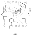
- Fig. 1 shows the basic concept of the invention.
- a microwave reader M comprising a reader unit 1, sometimes referred to as interrogator unit or transmitter/receiver device, and an antenna array 2, emits in operation an electromagnetic wave 4 in the direction of a responder 5.
- the responder 5 comprises means for modulating a received microwave signal with information from a data carrier (not shown separately), which is part of the responder.
- the data carrier comprises at least a binary memory section, while, further, associated digital circuits for feeding data to the memory section and reading the content of the memory section or particular memory locations thereof are provided.
- the responder further comprises means 12 for reflecting a modulated electromagnetic wave 3 in the direction of the reader M.
- the responder further comprises means 16 for exchanging data with the responder by means of an inductive read/write station which may or may not be portable.
- the drawing shows a portable, inductively operating transmitter/receiver device H, comprising a read/write unit 6 and an antenna device 7 by means of which an inductive coupling (indicated at 8a) between the device H and the responder 5, in particular the means 16, can be effected.
- a fixedly arranged inductive read/write station I comprising an antenna 10 and a read/write unit 9 can in operation exchange data with the responder via an inductive coupling 8b.
- Fig. 2 illustrates the operation of a microwave system and in particular a system based on the retroreflective principle, which system makes a long identification path possible, so that objects with a high velocity of motion can be identified as well.
- the data speed across the connection can yet be low and be in agreement with the data speed associated with inductive systems.
- a microwave reader with an interrogator unit 1 and an antenna array 2 emits in operation an electromagnetic wave 4 which forms a broad beam in the plane of the expected motion of the object and forms a narrow beam in a plane perpendicular thereto.
- Such a substantially fan-shaped beam with a large range can be generated without the necessity of large antennas.
- the responder is shown in two positions, indicated by 5 and 5', and comprises means for modulating the received wave with information from a data carrier and for reflecting it, as indicated at 37, in the direction of the antenna array 2 of the interrogator station.
- Fig. 3 schematically shows an arrangement with an inductively operating identification system.
- the interrogation antenna 10 or assembly of antennas of the inductive identification system should have dimensions A, at least in the direction of motion of the objects 5, of the order of the length of the identification path 11, which is necessary to enable identification of fast moving objects with a certain data speed.
- this drawback can be obviated according to the invention by using a microwave interrogator unit as indicated in Figs. 1 and 2, in combination with a responder which can be identified or read and optionally programmed both in the conventional inductive manner and by means of microwaves.
- a microwave interrogator unit as indicated in Figs. 1 and 2
- a responder which can be identified or read and optionally programmed both in the conventional inductive manner and by means of microwaves.
- the possibility of reading and programming with a read/write unit is maintained by the integration of both interface techniques in the responder.
- Fig. 4 schematically shows an exemplary embodiment of an integrated microwave/inductive responder 40 without a battery.
- the responder 40 comprises a microwave interface 12, formed preferably by a patch antenna array, which provides for the relay of a received microwave signal to a demodulator/modulator unit 13.
- the received microwave signal has been modulated in the transmitter/receiver device with a frequency which is suitable for use in an inductively operating identification system.
- this frequency may also be the clock frequency of the digital electronic part of the responder.
- the demodulator/modulator unit 13 provides for the detection of the clock signal, for the modulation of the signal to be reflected with data, supplied via a line 46 from an electronic data carrier 14, forming part of the responder, and for the retroreflection of the now modulated received microwave energy in the direction of the interrogator station.
- the clock signal obtained by demodulation is applied to the data carrier via a line 42, 43 and also to an AC/DC converter 15 via a line 44, which converter 15 forms a DC supply voltage from the clock signal provided and feeds it to the data carrier 14 via line 45.
- the inductive interface 16 preferably comprising an air-cored coil or a coil wound onto a ferrite rod, supplies the energy induced in the coil by a transmitter/receiver device I, which energy, to advantage, again has a frequency equal to the clock frequency for the data carrier 14, to the data carrier 14 via line 48, 43, and further to an AC/DC converter 17 and a modulator 18.
- the modulator 18 modulates the induced energy in the inductive interface 16 with information obtained via a line 49 from the data carrier, enabling transfer of information from the data carrier to a portable read/write unit or fixed inductive interrogator station.
- a modulated supply voltage for the data carrier is formed, which modulation is demodulated by means of a detector 50 and is translated into data which is stored in the data carrier.
- the coil of the inductive interface may be tuned to a predetermined frequency corresponding to a frequency of the interrogation field, by means of a capacitor. However, this is not strictly necessary.
- the data carrier can also be programmed by using the (clock) signal modulated on the microwave signal as auxiliary carrier wave for the data to be written in the data carrier, reaching the detector 50 via line 45.
- Fig. 5 schematically shows an exemplary embodiment of an integrated microwave/inductive responder provided with battery supply.
- the responder again comprises a microwave interface 12, preferably a patch antenna array, which provides for the relay of a microwave signal preferably modulated with the clock frequency for the electronic part, to a demodulator/modulator unit 13.
- the received microwave energy may be smaller by one order than in the responder of Fig. 4, so that the transmitting power of the interrogation station can be small.
- the demodulator/modulator unit 13 provides for the detection of the clock signal and for the modulation of the received microwave energy with information supplied from the data carrier via a line 51 and for the (retro)reflection of the modulated received microwave energy in the direction of the interrogator unit.
- the demodulated clock signal is supplied via a line 52 to an amplifier 19, which brings the clock signal to a level suitable for use by the data carrier 14.
- the amplifier 19 is an amplifier with a very low energy consumption, so that it is possible for this amplifier to be continuously connected with the energy source 20.
- the energy source 20 can for instance be a lithium battery or a solar cell.
- An integrator 21 integrates and filters the amplified clock signal and will, if the clock signal is present sufficiently long, operate a DC voltage switch 22, for instance a suitable FET or CMOS gate, which connects the energy source 20 via line 53 with the data carrier 14.
- a DC voltage switch 22 for instance a suitable FET or CMOS gate, which connects the energy source 20 via line 53 with the data carrier 14.
- the received clock signal accordingly functions as a "wake-up" signal for the responder.
- the inductive interface 16 preferably comprising a tuned or non-tuned air-cored coil or a coil wound onto a ferrite rod, supplies the energy induced by the inductive transmitter/receiver device, which energy may again advantageously have a frequency equal to the clock frequency for the data carrier 14, to an AC/DC converter 17 and demodulator 18.
- the AC/DC converter 17 again supplies a DC voltage for the data carrier.
- the modulator 18 modulates the induced energy in the inductive interface 16 with data from the data carrier 14, which enables transfer of data from the data carrier to a read/write unit or fixedly arranged inductive interrogation station.
- converter 17 By modulation of the induced energy originating from a fixed or portable read/write unit, there is formed via converter 17 a modulated supply voltage for the data carrier, which demodulates this modulation by means of detector 5 and translates it into data which is stored in the data carrier.
- Fig. 6 schematically shows an exemplary embodiment of an integrated microwave/inductive responder, where the data carrier is removable from the responder.
- the removable data carrier can be coupled with the responder via contacts but is preferably inductively coupled with the responder.
- the integrated responder 5 shown comprises a conductive interface, schematically indicated at 16, a microwave interface 12, a battery 20 and/or a plurality of solar cells 23 and a slot 24 via which a removable data carrier 25 can be slipped into the responder housing 61.
- the insert unit 25 comprises its own inductive interface 26 formed by an antenna coil conventional for inductively operating responders, which antenna coil may optionally be part of a tuned circuit with a predetermined resonant frequency.
- the data carrier After insertion of a removable unit 25, which contains the data carrier, and in the presence of an electromagnetic wave 4, modulated with a clock signal, the data carrier will yield information to, or receive information from, the integrated responder 5 via the inductive coupling 8.
- the information from the data carrier of the insert unit 25 will be modulated on the received microwave energy 4 by the modulator 13 (see Fig. 4 or 5) and be (retro)reflected in the direction of the interrogator unit M, which comprises a transmitter/receiver antenna 2 and a transmitter/receiver unit 1.
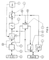
- Fig. 7 schematically shows in more detail an embodiment of an integrated microwave/inductive responder, supplied by a battery and/or solar cell, the data carrier of this responder being removable.
- the removable data carrier is constructed as insert unit 25 and comprises the data carrier proper 14 with a control and storage function, an AC/DC converter 17, which may be a conventional rectifier, a modulator 18 and an inductive interface 26, preferably comprising an air-cored coil or a tuned or non-tuned coil wound onto a ferrite rod.
- the insert unit couples contactlessly via the magnetic field 8 with the inductive interface 16 of the integrated responder 5.
- the responder further comprises a microwave interface 12, preferably designed with a patch antenna array, which provides for the relay of the microwave signal, modulated with a predetermined frequency, to a demodulator/modulator unit 13.
- the predetermined frequency again, can advantageously be equal to the clock frequency of the data carrier, but may also have a value such that the clock frequency can be derived therefrom relatively simply. This also applies to the previously described examples.
- the received microwave energy can be smaller by one order than with the passive responder shown in Fig. 4, so that the transmitting power of the interrogator station can be small.
- the demodulator/modulator unit 13 provides for the detection of the clock signal and for the modulation of the received microwave energy with information provided by the removable insert unit 25 via the inductive interface 26, 8, 16, and for the (retro)reflection of the thus modulated microwave energy in the direction of the interrogator unit.
- the detected clock signal is applied to an amplifier 19 which brings the clock signal to a level suitable for driving a second amplifier 27.
- the second amplifier provides the inductive interface 26, via an adapter filter 28 and coil 16, with sufficient energy to activate the insert unit 25.
- the amplifier 19 is an amplifier with a very low energy consumption, so that this amplifier can be allowed to be continuously connected with the energy source 20.
- the energy source 20 preferably consists a lithium battery or one or more solar cells 23 (see Fig. 6).
- the integrator 21 integrates and filters the received clock signal and will, if the clock signal is present sufficiently long, operate a DC voltage switch 22, which connects the energy source 20 with a threshold detector 29, the amplifier 27 and an encoder 30, so as to limit the energy consumption of the responder in the "sleep" mode as much as possible.
- the received clock signal accordingly functions as "wake-up" signal for the responder and also as interrogation or read signal for the insert unit.
- the inductive interface 16 preferably consisting of an air-cored coil or a coil wound onto a ferrite rod, delivers the clock signal modulated by the removable insert unit to a detector 31.
- filter 32 After filtering by filter 32, which filters out the carrier wave frequency (clock signal frequency) and limits the band width, the output signal of the detector is applied to a threshold detector 29, which makes the amplitude and flanks of the received data suitable for driving the encoder 30.
- This encoder modulates the data on a subcarrier wave, which is derived from the received signal, which is directed via a line 60 from the output of the amplifier 19 to the encoder 30.
- the subcarrier wave may for instance have a frequency which is half the frequency of the clock signal.
- This modulated subcarrier wave is modulated on the received microwave energy by the demodulator/modulator 13 and, via the microwave interface 12, (retro)reflected in the direction of the interrogating station.
- the insert unit can be programmed in the simplest manner by bringing the loose unit into the field of a suitable inductive read/write device.
- the insert unit can also be programmed via the microwave interface 12 (by modulation of the clock signal) while the insert unit is situated in the integrated responder. It is even conceivable that the insert unit in inserted condition is programmed via the inductive interface.
- a loose insert unit In the case of a loose insert unit, it may be passive and designed to draw supply energy from the interrogation field, but it is also possible to provide the loose insert unit with its own energy source, for instance a battery. This increases the possibilities of using the insert unit independently, i.e., at a distance from the housing of the responder with the microwave part and the inductive interface 16.
- the described system with integrated or combined responder assembly adequately provides for the need to make it possible for an inductive data carrier (such as a pass, a credit card, a smart card, etc.) which is used, for instance, for automatic admission to buildings or the like, to be used as well for identification at larger distances and/or for identification of objects moving at a relatively high velocity or persons located in such objects.
- an inductive data carrier such as a pass, a credit card, a smart card, etc.
- Examples in point include admission systems for parking lots or multi-story parking garages, toll systems and the like.
- the microwave frequency can, for instance, be between 1 GHz and 100 GHz.
- the frequency for inductive coupling lies in the radio-frequency range and may for instance be about 120 kHz.
- the same frequency can be used for modulation of the interrogation signal emitted by the microwave transmitter/receiver device.
- the auxiliary carrier wave on which the data is modulated by the encoder 30 can for instance be 60 kHz or another submultiple of the frequency used for the inductive coupling.
Landscapes
- Engineering & Computer Science (AREA)
- Physics & Mathematics (AREA)
- General Physics & Mathematics (AREA)
- Theoretical Computer Science (AREA)
- Computer Networks & Wireless Communication (AREA)
- Computer Hardware Design (AREA)
- Microelectronics & Electronic Packaging (AREA)
- Artificial Intelligence (AREA)
- Computer Vision & Pattern Recognition (AREA)
- Near-Field Transmission Systems (AREA)
- Radar Systems Or Details Thereof (AREA)
- Materials For Photolithography (AREA)
Abstract
Disclosed is a system for the contactless exchange of data between one or more transmitter/receiver devices and a plurality of responders. According to the invention, at least one of the responders is designed to exchange data via a microwave connection with a transmitter/receiver device operating in the microwave range, and to exchange data via an inductive coupling with an inductively operating transmitter/receiver device.
Description
- The invention relates to a system for the contactless exchange of data between a transmitter/receiver device and a responder. The invention further relates to a responder for use in such a system. In practice, such responders are also designated by other terms, such as, for instance, transponder, data carrier, label, electronic pass, chip card, etc.
- For the transmitter/receiver device, too, various other designations are used, such as, for instance, interrogator or reader. Further, it is not strictly necessary for the transmitter, which can generate an interrogation field, to be combined into a single unit together with the receiver device. The terms as used hereinafter should be interpreted in the sense indicated hereinabove.
- Systems for the contactless exchange of data are known in different designs and types. Applicant's Dutch patent 176,404, for instance, describes a system comprising a passive responder, i.e., a responder which does not possess a battery of its own and which draws the supply energy required for the functioning of the active electronic components of the responder circuit from the electromagnetic interrogation field, by means of which digital information stored in the responder can be detected. Similar systems, where the responders do comprise a battery, are also known. Further, systems are known which provide the possibility of contactless modification of data stored in the memory of a responder. Such reprogramming of responders can be effected with the interrogator device employed for normal use, adapted for that purpose, or with a special writing device or reprogramming device. Such a system is for instance described in applicant's European patent 0,242,906. A reprogrammable responder may also comprise one or more sensors which can observe a physical parameter and store the value thereof in the memory of the responder. Such a system is disclosed in applicant's European patent application 0,395,188.
- Applicant's Dutch patent application 9,002,683 discloses an identification system operative in the microwave range, with a microwave responder with retroreflective properties. Microwave systems have an advantage over inductively operating responder systems in that a relatively large detection distance between transmitter/receiver and responder and a higher velocity of motion of the object to be identified are possible utilizing relatively small antenna dimensions. However, a drawback is that microwave apparatus is relatively complex. In particular, portable readers and portable programming devices for the responders are difficult to make. Portable inductively operating readers and programming devices are simpler to realize than comparable microwave devices. On the other hand, a drawback of inductively operating systems is that although it is very well possible to read and program responders at a relatively short distance, an increase of the identification path with a view to identifying (fast) moving objects is very troublesome. For this purpose, antennas must be used which have dimensions of the order of magnitude of the desired identification path. This is in contrast with what is the case with microwave identification systems.
- For a number of applications, a random example being the logistic handling of product flows, there is a need for an identification system which combines the advantages of a microwave system with the advantages of an inductive system. The object of the present invention is to provide for this need. To that end, according to the invention, a system of the above-described type is characterized in that at least one of the responders is designed to exchange data via a microwave connection, with a transmitter/receiver device operating in the microwave range and to exchange data via an inductive coupling, with an inductively operating transmitter/receiver device.
- Hereinafter, the invention will be further described with reference to the accompanying drawings of some exemplary embodiments.
- Fig. 1 schematically shows an example of a system according to the invention;
- Fig. 2 illustrates the operation of a microwave system for contactless data exchange;
- Fig. 3 illustrates the operation of an inductively operating system for contactless data exchange;
- Fig. 4 shows a block diagram of an exemplary embodiment of a responder for a system according to the invention;
- Fig. 5 shows a block diagram of a second exemplary embodiment of a responder for a system according to the invention;
- Fig. 6 schematically shows a system according to the invention comprising a special responder; and
- Fig. 7 shows a block diagram of a responder according to Fig. 6.
- Fig. 1 shows the basic concept of the invention. A microwave reader M, comprising a
reader unit 1, sometimes referred to as interrogator unit or transmitter/receiver device, and anantenna array 2, emits in operation anelectromagnetic wave 4 in the direction of aresponder 5. Theresponder 5 comprises means for modulating a received microwave signal with information from a data carrier (not shown separately), which is part of the responder. The data carrier comprises at least a binary memory section, while, further, associated digital circuits for feeding data to the memory section and reading the content of the memory section or particular memory locations thereof are provided. The responder further comprises means 12 for reflecting a modulatedelectromagnetic wave 3 in the direction of the reader M. The responder further comprises means 16 for exchanging data with the responder by means of an inductive read/write station which may or may not be portable. - The drawing shows a portable, inductively operating transmitter/receiver device H, comprising a read/write
unit 6 and anantenna device 7 by means of which an inductive coupling (indicated at 8a) between the device H and theresponder 5, in particular themeans 16, can be effected. - A fixedly arranged inductive read/write station I, comprising an
antenna 10 and a read/writeunit 9 can in operation exchange data with the responder via aninductive coupling 8b. - Fig. 2 illustrates the operation of a microwave system and in particular a system based on the retroreflective principle, which system makes a long identification path possible, so that objects with a high velocity of motion can be identified as well. The data speed across the connection, however, can yet be low and be in agreement with the data speed associated with inductive systems.
- A microwave reader with an
interrogator unit 1 and anantenna array 2 emits in operation anelectromagnetic wave 4 which forms a broad beam in the plane of the expected motion of the object and forms a narrow beam in a plane perpendicular thereto. Such a substantially fan-shaped beam with a large range can be generated without the necessity of large antennas. With an inductive coupling, a comparable range could only be realized by using an antenna coil with dimensions of the order of magnitude of the object to be identified. The responder is shown in two positions, indicated by 5 and 5', and comprises means for modulating the received wave with information from a data carrier and for reflecting it, as indicated at 37, in the direction of theantenna array 2 of the interrogator station. By using a responder with retroreflective properties, anidentification path 11 of extended length is created, so that the responder, in spite of its high velocity of motion V, can yet be read at a relatively low data speed. - Fig. 3, for comparison, schematically shows an arrangement with an inductively operating identification system. The
interrogation antenna 10 or assembly of antennas of the inductive identification system should have dimensions A, at least in the direction of motion of theobjects 5, of the order of the length of theidentification path 11, which is necessary to enable identification of fast moving objects with a certain data speed. - As will be explained in more detail hereinafter, this drawback can be obviated according to the invention by using a microwave interrogator unit as indicated in Figs. 1 and 2, in combination with a responder which can be identified or read and optionally programmed both in the conventional inductive manner and by means of microwaves. The possibility of reading and programming with a read/write unit is maintained by the integration of both interface techniques in the responder.
- Fig. 4 schematically shows an exemplary embodiment of an integrated microwave/
inductive responder 40 without a battery. Theresponder 40 comprises amicrowave interface 12, formed preferably by a patch antenna array, which provides for the relay of a received microwave signal to a demodulator/modulator unit 13. The received microwave signal has been modulated in the transmitter/receiver device with a frequency which is suitable for use in an inductively operating identification system. Advantageously, this frequency may also be the clock frequency of the digital electronic part of the responder. The demodulator/modulator unit 13 provides for the detection of the clock signal, for the modulation of the signal to be reflected with data, supplied via aline 46 from anelectronic data carrier 14, forming part of the responder, and for the retroreflection of the now modulated received microwave energy in the direction of the interrogator station. The clock signal obtained by demodulation is applied to the data carrier via aline DC converter 15 via aline 44, which converter 15 forms a DC supply voltage from the clock signal provided and feeds it to thedata carrier 14 vialine 45. - In inductive operation, the
inductive interface 16, preferably comprising an air-cored coil or a coil wound onto a ferrite rod, supplies the energy induced in the coil by a transmitter/receiver device I, which energy, to advantage, again has a frequency equal to the clock frequency for thedata carrier 14, to thedata carrier 14 vialine DC converter 17 and amodulator 18. The AC/DC converter 17, for instance a rectifier, again supplies a DC supply voltage for thedata carrier 14 via aline 47. Themodulator 18 modulates the induced energy in theinductive interface 16 with information obtained via aline 49 from the data carrier, enabling transfer of information from the data carrier to a portable read/write unit or fixed inductive interrogator station. Through modulation of the induced energy originating from the fixed or portable read/write unit, a modulated supply voltage for the data carrier is formed, which modulation is demodulated by means of adetector 50 and is translated into data which is stored in the data carrier. The coil of the inductive interface may be tuned to a predetermined frequency corresponding to a frequency of the interrogation field, by means of a capacitor. However, this is not strictly necessary. - In principle, the data carrier can also be programmed by using the (clock) signal modulated on the microwave signal as auxiliary carrier wave for the data to be written in the data carrier, reaching the
detector 50 vialine 45. - Fig. 5 schematically shows an exemplary embodiment of an integrated microwave/inductive responder provided with battery supply. The responder again comprises a
microwave interface 12, preferably a patch antenna array, which provides for the relay of a microwave signal preferably modulated with the clock frequency for the electronic part, to a demodulator/modulator unit 13. Because of the battery supply, the received microwave energy may be smaller by one order than in the responder of Fig. 4, so that the transmitting power of the interrogation station can be small. - The demodulator/
modulator unit 13 provides for the detection of the clock signal and for the modulation of the received microwave energy with information supplied from the data carrier via aline 51 and for the (retro)reflection of the modulated received microwave energy in the direction of the interrogator unit. The demodulated clock signal is supplied via aline 52 to anamplifier 19, which brings the clock signal to a level suitable for use by thedata carrier 14. Theamplifier 19 is an amplifier with a very low energy consumption, so that it is possible for this amplifier to be continuously connected with theenergy source 20. Theenergy source 20 can for instance be a lithium battery or a solar cell. - An
integrator 21 integrates and filters the amplified clock signal and will, if the clock signal is present sufficiently long, operate aDC voltage switch 22, for instance a suitable FET or CMOS gate, which connects theenergy source 20 vialine 53 with thedata carrier 14. Thus, the energy consumption of the responder in the "sleep" mode can be limited as much as possible. The received clock signal accordingly functions as a "wake-up" signal for the responder. - During inductive operation, the
inductive interface 16, preferably comprising a tuned or non-tuned air-cored coil or a coil wound onto a ferrite rod, supplies the energy induced by the inductive transmitter/receiver device, which energy may again advantageously have a frequency equal to the clock frequency for thedata carrier 14, to an AC/DC converter 17 anddemodulator 18. The AC/DC converter 17 again supplies a DC voltage for the data carrier. Similarly to the embodiment of Fig. 4, themodulator 18 modulates the induced energy in theinductive interface 16 with data from thedata carrier 14, which enables transfer of data from the data carrier to a read/write unit or fixedly arranged inductive interrogation station. - By modulation of the induced energy originating from a fixed or portable read/write unit, there is formed via converter 17 a modulated supply voltage for the data carrier, which demodulates this modulation by means of
detector 5 and translates it into data which is stored in the data carrier. - Fig. 6 schematically shows an exemplary embodiment of an integrated microwave/inductive responder, where the data carrier is removable from the responder. The removable data carrier can be coupled with the responder via contacts but is preferably inductively coupled with the responder. The
integrated responder 5 shown comprises a conductive interface, schematically indicated at 16, amicrowave interface 12, abattery 20 and/or a plurality ofsolar cells 23 and aslot 24 via which aremovable data carrier 25 can be slipped into theresponder housing 61. Theinsert unit 25 comprises its owninductive interface 26 formed by an antenna coil conventional for inductively operating responders, which antenna coil may optionally be part of a tuned circuit with a predetermined resonant frequency. - After insertion of a
removable unit 25, which contains the data carrier, and in the presence of anelectromagnetic wave 4, modulated with a clock signal, the data carrier will yield information to, or receive information from, theintegrated responder 5 via theinductive coupling 8. - The information from the data carrier of the
insert unit 25 will be modulated on the receivedmicrowave energy 4 by the modulator 13 (see Fig. 4 or 5) and be (retro)reflected in the direction of the interrogator unit M, which comprises a transmitter/receiver antenna 2 and a transmitter/receiver unit 1. - Fig. 7 schematically shows in more detail an embodiment of an integrated microwave/inductive responder, supplied by a battery and/or solar cell, the data carrier of this responder being removable. The removable data carrier is constructed as
insert unit 25 and comprises the data carrier proper 14 with a control and storage function, an AC/DC converter 17, which may be a conventional rectifier, amodulator 18 and aninductive interface 26, preferably comprising an air-cored coil or a tuned or non-tuned coil wound onto a ferrite rod. Via theinterface 26, the insert unit couples contactlessly via themagnetic field 8 with theinductive interface 16 of theintegrated responder 5. The responder further comprises amicrowave interface 12, preferably designed with a patch antenna array, which provides for the relay of the microwave signal, modulated with a predetermined frequency, to a demodulator/modulator unit 13. The predetermined frequency, again, can advantageously be equal to the clock frequency of the data carrier, but may also have a value such that the clock frequency can be derived therefrom relatively simply. This also applies to the previously described examples. The received microwave energy can be smaller by one order than with the passive responder shown in Fig. 4, so that the transmitting power of the interrogator station can be small. During microwave operation in the manner described, the demodulator/modulator unit 13 provides for the detection of the clock signal and for the modulation of the received microwave energy with information provided by theremovable insert unit 25 via theinductive interface amplifier 19 which brings the clock signal to a level suitable for driving asecond amplifier 27. The second amplifier provides theinductive interface 26, via anadapter filter 28 andcoil 16, with sufficient energy to activate theinsert unit 25. Theamplifier 19 is an amplifier with a very low energy consumption, so that this amplifier can be allowed to be continuously connected with theenergy source 20. Theenergy source 20 preferably consists a lithium battery or one or more solar cells 23 (see Fig. 6). - The
integrator 21 integrates and filters the received clock signal and will, if the clock signal is present sufficiently long, operate aDC voltage switch 22, which connects theenergy source 20 with athreshold detector 29, theamplifier 27 and anencoder 30, so as to limit the energy consumption of the responder in the "sleep" mode as much as possible. - The received clock signal accordingly functions as "wake-up" signal for the responder and also as interrogation or read signal for the insert unit. The
inductive interface 16, preferably consisting of an air-cored coil or a coil wound onto a ferrite rod, delivers the clock signal modulated by the removable insert unit to adetector 31. After filtering byfilter 32, which filters out the carrier wave frequency (clock signal frequency) and limits the band width, the output signal of the detector is applied to athreshold detector 29, which makes the amplitude and flanks of the received data suitable for driving theencoder 30. This encoder modulates the data on a subcarrier wave, which is derived from the received signal, which is directed via aline 60 from the output of theamplifier 19 to theencoder 30. In a practical situation, the subcarrier wave may for instance have a frequency which is half the frequency of the clock signal. This modulated subcarrier wave is modulated on the received microwave energy by the demodulator/modulator 13 and, via themicrowave interface 12, (retro)reflected in the direction of the interrogating station. - The insert unit can be programmed in the simplest manner by bringing the loose unit into the field of a suitable inductive read/write device. In principle, the insert unit can also be programmed via the microwave interface 12 (by modulation of the clock signal) while the insert unit is situated in the integrated responder. It is even conceivable that the insert unit in inserted condition is programmed via the inductive interface.
- It is observed that after the foregoing, various modifications will readily occur to a person of ordinary skill in the art. It has already been mentioned that it is possible to effect the inductive couplings by means of coils that may or may not be tuned. Further, in the foregoing, there was presumed an inductive interrogation field provided by a portable or non-portable inductive read/write unit or the like, or, in the case of an insert unit, by the inductive interface of the responder, the frequency of which is equal to the clock frequency required for the data carrier. However, the clock frequency could also be derived from the frequency of the interrogation field, for instance by frequency division or multipication. Nor is it strictly necessary that the frequency modulated on the interrogating microwave signal is equal to the clock frequency of the data carrier.
- In the case of a loose insert unit, it may be passive and designed to draw supply energy from the interrogation field, but it is also possible to provide the loose insert unit with its own energy source, for instance a battery. This increases the possibilities of using the insert unit independently, i.e., at a distance from the housing of the responder with the microwave part and the
inductive interface 16. - The described system with integrated or combined responder assembly adequately provides for the need to make it possible for an inductive data carrier (such as a pass, a credit card, a smart card, etc.) which is used, for instance, for automatic admission to buildings or the like, to be used as well for identification at larger distances and/or for identification of objects moving at a relatively high velocity or persons located in such objects. Examples in point include admission systems for parking lots or multi-story parking garages, toll systems and the like.
- The microwave frequency can, for instance, be between 1 GHz and 100 GHz. The frequency for inductive coupling lies in the radio-frequency range and may for instance be about 120 kHz. The same frequency can be used for modulation of the interrogation signal emitted by the microwave transmitter/receiver device. The auxiliary carrier wave on which the data is modulated by the
encoder 30 can for instance be 60 kHz or another submultiple of the frequency used for the inductive coupling. - An additional advantage of the use of a combined responder is that if in embodiments as shown, for instance, in Figs. 4, 5, 6 and 7, the
battery 20 is empty, it remains possible to read out the data carrier via the inductive route. The above-mentioned and similar modifications are understood to fall within the scope of the invention.
Claims (22)
- A system for the contactless exchange of data between one or more transmitter/receiver devices and a plurality of responders, characterized in that at least one of the responders is designed to exchange data via a microwave connection with a transmitter/receiver device operating in the microwave range and to exchange data via an inductive coupling with an inductively operating transmitter/receiver device.
- A system according to claim 1, characterized in that the at least one responder comprises a microwave antenna device, an inductively operating antenna device, and a data carrier, in which data is stored, whilst between the data carrier and the microwave antenna device means are connected for modulating a received microwave signal with data stored in the data carrier, and between the data carrier and the inductively operating antenna device means are connected for modulating an inductively received signal with data stored in the data carrier.
- A system according to claim 2, characterized in that the microwave antenna device is designed for retroreflection of microwave energy.
- A system according to claim 2 or 3, characterized in that the microwave antenna device is connected with a demodulator, which can demodulate a signal modulated on a received microwave signal and can apply the signal obtained after demodulation to the data carrier.
- A system according to claim 4, characterized in that the signal obtained after demodulation is converted via a first AC/DC converter into supply voltage for the responder.
- A system according to any one of claims 2-5, characterized in that the microwave antenna device is connected with a modulator, which is further connected with the data carrier and which can modulate data provided by the data carrier on microwave energy received by the microwave antenna device.
- A system according to any one of claims 2-6, characterized in that the inductively operating antenna device is connected with a second AC/DC converter, which in operation converts energy received by the antenna device into a DC supply voltage for the responder.
- A system according to claims 4 and 7, characterized in that, of the first and the second AC/DC converters, at least the second AC/DC converter is connected with a detector, which can demodulate data modulated on the supply voltage and can store the data in the data carrier.
- A system according to any one of the preceding claims, characterized in that an inductive transmitter/receiver device, belonging to the system, is designed to generate an electromagnetic field with a predetermined frequency and that a microwave transmitter/receiver device, belonging to the system, is designed to emit a microwave signal on which a signal with the same frequency as the said predetermined frequency or with a frequency from which the predetermined frequency can simply be derived, has been modulated.
- A system according to claim 9, characterized in that, of the inductive transmitter/receiver devices and the microwave transmitter/receiver devices, at least a number of inductive transmitter/receiver devices are designed for modulating the predetermined frequency with a data signal.
- A system according to any one of claims 4-10, characterized in that the demodulator connected with the microwave antenna device is connected with a switching means via at least an integrator, which switching means, if the voltage built up by the integrator achieves a predetermined threshold value, connects an internal supply source provided in the responder with at least the data carrier.
- A system according to claim 11, characterized in that between the demodulator and the integrator an amplifier with a low energy consumption is connected, which is permanently connected with the supply source.
- A system according to any one of the preceding claims, characterized in that the data carrier is provided on a separate insert unit, which can be removably placed in a purposely formed receiving space of the housing of the responder.
- A system according to claim 13, characterized in that the insert unit is provided with its own antenna coil device for contactless inductive coupling with the inductively operating antenna device of the associated responder.
- A system according to claim 14, characterized in that the insert unit comprises a memory section, a modulator and a demodulator for modulating and demodulating, respectively, energy induced in the antenna coil device.
- A system according to claim 15, characterized in that the insert unit is provided with its own internal energy source.
- A system according to any one of claims 13-16, characterized in that the means for modulating a received microwave signal comprise an encoder which receives data provided by the data carrier and modulates it on an auxiliary carrier wave and applies the modulated auxiliary carrier wave to a modulator connected with the microwave antenna device, which modulator in operation modulates a received microwave signal with the modulated auxiliary carrier wave.
- A system according to claim 17, characterized in that the data from the data carrier reaches the encoder via a filter and a threshold detector.
- A system according to any one of claims 13-18, characterized in that the insert unit is constructed as a card.
- A system according to any one of claims 11-19, characterized in that the internal supply source comprises one or more solar cells.
- A responder for use in a system according to any one of the preceding claims.
- An insert unit for use in a system according to any one of claims 13-20.
Applications Claiming Priority (2)
| Application Number | Priority Date | Filing Date | Title |
|---|---|---|---|
| NL9201072 | 1992-06-18 | ||
| NL9201072A NL9201072A (en) | 1992-06-18 | 1992-06-18 | INTEGRATED MICROWAVE / INDUCTIVE TRANSPONDER. |
Publications (1)
| Publication Number | Publication Date |
|---|---|
| EP0575013A1 true EP0575013A1 (en) | 1993-12-22 |
Family
ID=19860939
Family Applications (1)
| Application Number | Title | Priority Date | Filing Date |
|---|---|---|---|
| EP93201767A Withdrawn EP0575013A1 (en) | 1992-06-18 | 1993-06-18 | System for the contactless exchange of data, and responder for use in such a system |
Country Status (4)
| Country | Link |
|---|---|
| US (1) | US5426667A (en) |
| EP (1) | EP0575013A1 (en) |
| CA (1) | CA2098790A1 (en) |
| NL (1) | NL9201072A (en) |
Cited By (6)
| Publication number | Priority date | Publication date | Assignee | Title |
|---|---|---|---|---|
| FR2779847A1 (en) * | 1998-06-16 | 1999-12-17 | Regie Autonome Transports | PORTABLE OBJECT FOR CONTACTLESS COMMUNICATION FOLLOWING TWO WAYS OF COMMUNICATION, INDUCTIVE AND HERTZIAN |
| NL1014126C2 (en) * | 2000-01-20 | 2001-07-23 | Nedap Nv | Detection system recognizes passage of persons or goods through gate, combines advantages of inductive electromagnetic loop method with those of short wave radio method |
| FR2824943A1 (en) * | 2001-05-21 | 2002-11-22 | Siemens Automotive Sa | Badge to vehicle communication procedure for hands free unlocking |
| WO2006136212A2 (en) * | 2005-06-22 | 2006-12-28 | Siemens Schweiz Ag | Method, electronic cover, and access unit for providing access to a zone by means of a card |
| EP1804220A1 (en) | 2005-12-29 | 2007-07-04 | AXSionics AG | Method for authorised provision of a service and portable device for the implementation thereof |
| EP2058750A1 (en) * | 2007-11-09 | 2009-05-13 | Unified Packet Systems Corp. | Microwave control system |
Families Citing this family (33)
| Publication number | Priority date | Publication date | Assignee | Title |
|---|---|---|---|---|
| FI103820B (en) * | 1993-11-30 | 1999-09-30 | Valmet Paper Machinery Inc | Procedures for drying a paper web and drying parts for paper machine |
| DE29514235U1 (en) * | 1995-09-05 | 1996-06-05 | Siemens Ag | Device for the contactless transmission of data to mobile data carriers with proximity protection |
| SE9600015D0 (en) * | 1996-01-02 | 1996-01-02 | Tagmaster Ab | Device and system with three data carriers |
| US5834756A (en) * | 1996-06-03 | 1998-11-10 | Motorola, Inc. | Magnetically communicative card |
| JPH1091866A (en) | 1996-09-18 | 1998-04-10 | Hitachi Ltd | Electronic money transaction system |
| US5815020A (en) * | 1996-09-24 | 1998-09-29 | Motorola, Inc. | Balance differential receiver |
| US5812942A (en) * | 1996-09-24 | 1998-09-22 | Motorola, Inc. | Balanced differential radio receiver and method of operation |
| US6243012B1 (en) | 1996-12-31 | 2001-06-05 | Lucent Technologies Inc. | Inexpensive modulated backscatter reflector |
| US6130623A (en) * | 1996-12-31 | 2000-10-10 | Lucent Technologies Inc. | Encryption for modulated backscatter systems |
| US5784686A (en) * | 1996-12-31 | 1998-07-21 | Lucent Technologies Inc. | IQ combiner technology in modulated backscatter system |
| US6184841B1 (en) | 1996-12-31 | 2001-02-06 | Lucent Technologies Inc. | Antenna array in an RFID system |
| US6046683A (en) * | 1996-12-31 | 2000-04-04 | Lucent Technologies Inc. | Modulated backscatter location system |
| US5952922A (en) * | 1996-12-31 | 1999-09-14 | Lucent Technologies Inc. | In-building modulated backscatter system |
| US6456668B1 (en) | 1996-12-31 | 2002-09-24 | Lucent Technologies Inc. | QPSK modulated backscatter system |
| FR2776407B1 (en) * | 1998-03-20 | 2001-06-08 | Gemplus Card Int | SYSTEM AND METHOD FOR PERFORMING PARTICULAR FUNCTIONS IN CONTACTLESS LABELS |
| US6879809B1 (en) | 1998-04-16 | 2005-04-12 | Motorola, Inc. | Wireless electrostatic charging and communicating system |
| US6282407B1 (en) * | 1998-04-16 | 2001-08-28 | Motorola, Inc. | Active electrostatic transceiver and communicating system |
| US6275681B1 (en) * | 1998-04-16 | 2001-08-14 | Motorola, Inc. | Wireless electrostatic charging and communicating system |
| DE19913093C2 (en) | 1999-03-23 | 2001-06-21 | Giesecke & Devrient Gmbh | Data carrier with a battery and a display |
| DE60006370T2 (en) * | 1999-03-26 | 2004-09-09 | Isis Innovation Ltd., Summertown | TRANSPONDERS |
| GB0003150D0 (en) * | 2000-02-12 | 2000-04-05 | Univ Newcastle | Navigation and routing system |
| US6369710B1 (en) | 2000-03-27 | 2002-04-09 | Lucent Technologies Inc. | Wireless security system |
| US6496121B2 (en) * | 2001-02-14 | 2002-12-17 | Ncr Corporation | Methods and apparatus for an electronic shelf label communication system |
| AU2003224365A1 (en) * | 2002-05-27 | 2003-12-12 | Koninklijke Philips Electronics N.V. | Passive data carrier with signal evaluation means for evaluating information of a self-clocking signal |
| CA2494175C (en) | 2002-08-08 | 2008-10-28 | Bnc Ip Switzerland Gmbh | Multi-frequency identification device |
| JP3979246B2 (en) * | 2002-09-30 | 2007-09-19 | ブラザー工業株式会社 | Communication system interrogator and interrogator |
| DE10253920A1 (en) * | 2002-11-19 | 2004-06-09 | Infineon Technologies Ag | Device for supplying a data transmission unit with energy |
| EP1641685A1 (en) * | 2003-07-04 | 2006-04-05 | Storsackeurea technology GmbH | Transport bag |
| US7482969B2 (en) * | 2006-06-14 | 2009-01-27 | Board Of Trustees Of The University Of Illinois | Material movement sensing techniques |
| US8508367B2 (en) | 2009-09-21 | 2013-08-13 | Checkpoint Systems, Inc. | Configurable monitoring device |
| MX2012003457A (en) | 2009-09-21 | 2012-08-03 | Checkpoint Systems Inc | Retail product tracking system, method, and apparatus. |
| US8099877B2 (en) | 2009-11-06 | 2012-01-24 | Hexagon Metrology Ab | Enhanced position detection for a CMM |
| DE102010042428A1 (en) * | 2010-10-13 | 2012-04-19 | E.G.O. Elektro-Gerätebau GmbH | Circuit for switching on and / or off an electrical consumer |
Citations (4)
| Publication number | Priority date | Publication date | Assignee | Title |
|---|---|---|---|---|
| EP0159539A1 (en) * | 1984-04-04 | 1985-10-30 | Siemens Aktiengesellschaft | Chip card system |
| EP0420180A1 (en) * | 1989-09-27 | 1991-04-03 | Nippon Soken, Inc. | Transponder for vehicle identification device |
| EP0446519A2 (en) * | 1990-03-13 | 1991-09-18 | Mitsubishi Denki Kabushiki Kaisha | Noncontact integrated circuit card |
| EP0459477A2 (en) * | 1990-05-30 | 1991-12-04 | MICO-DATA ELEKTRONISCHE STEUEREINRICHTUNGEN GmbH | Data carrier |
Family Cites Families (8)
| Publication number | Priority date | Publication date | Assignee | Title |
|---|---|---|---|---|
| US3689885A (en) * | 1970-09-15 | 1972-09-05 | Transitag Corp | Inductively coupled passive responder and interrogator unit having multidimension electromagnetic field capabilities |
| US3898565A (en) * | 1971-03-05 | 1975-08-05 | Mishima Kosan Co Ltd | Magnetic wave communication system |
| NL8601021A (en) * | 1986-04-22 | 1987-11-16 | Nedap Nv | PROGRAMMABLE RESPONDER. |
| JPH01236737A (en) * | 1988-03-16 | 1989-09-21 | Seiko Instr & Electron Ltd | Data gathering system |
| US5070500A (en) * | 1988-08-30 | 1991-12-03 | Tokyo Keiki Company Ltd. | Memory package system utilizing inductive coupling between memory module and read/write unit |
| JPH02249319A (en) * | 1989-03-22 | 1990-10-05 | Tokyo Keiki Co Ltd | Data communication system |
| NL8901079A (en) * | 1989-04-28 | 1990-11-16 | Nedap Nv | PASSIVE ELECTRONIC RECORDER. |
| FR2662320B1 (en) * | 1990-05-18 | 1994-05-13 | Cemagref | CONTACTLESS CONNECTION DEVICE FOR CONNECTING SERIES BUS LINES. |
-
1992
- 1992-06-18 NL NL9201072A patent/NL9201072A/en not_active Application Discontinuation
-
1993
- 1993-06-17 US US08/077,521 patent/US5426667A/en not_active Expired - Fee Related
- 1993-06-18 CA CA002098790A patent/CA2098790A1/en not_active Abandoned
- 1993-06-18 EP EP93201767A patent/EP0575013A1/en not_active Withdrawn
Patent Citations (4)
| Publication number | Priority date | Publication date | Assignee | Title |
|---|---|---|---|---|
| EP0159539A1 (en) * | 1984-04-04 | 1985-10-30 | Siemens Aktiengesellschaft | Chip card system |
| EP0420180A1 (en) * | 1989-09-27 | 1991-04-03 | Nippon Soken, Inc. | Transponder for vehicle identification device |
| EP0446519A2 (en) * | 1990-03-13 | 1991-09-18 | Mitsubishi Denki Kabushiki Kaisha | Noncontact integrated circuit card |
| EP0459477A2 (en) * | 1990-05-30 | 1991-12-04 | MICO-DATA ELEKTRONISCHE STEUEREINRICHTUNGEN GmbH | Data carrier |
Non-Patent Citations (3)
| Title |
|---|
| PATENT ABSTRACTS OF JAPAN vol. 13, no. 480 (P-952)31 October 1989 & JP-A-01 189 791 ( NEW JAPAN RADIO CO LTD ) 28 July 1989 * |
| PATENT ABSTRACTS OF JAPAN vol. 15, no. 509 (M-1195)24 December 1991 & JP-A-03 224 799 ( SONY CORP ) 3 October 1991 * |
| PATENT ABSTRACTS OF JAPAN vol. 17, no. 149 (P-1509)24 March 1993 & JP-A-04 319 791 ( NIPPONDENSO CO LTD ) 10 November 1992 * |
Cited By (12)
| Publication number | Priority date | Publication date | Assignee | Title |
|---|---|---|---|---|
| FR2779847A1 (en) * | 1998-06-16 | 1999-12-17 | Regie Autonome Transports | PORTABLE OBJECT FOR CONTACTLESS COMMUNICATION FOLLOWING TWO WAYS OF COMMUNICATION, INDUCTIVE AND HERTZIAN |
| WO1999066451A1 (en) * | 1998-06-16 | 1999-12-23 | Regie Autonome Des Tranports Parisiens (Ratp) | Portable object with contactless communication through two communication channels, inductive and radio wave |
| NL1014126C2 (en) * | 2000-01-20 | 2001-07-23 | Nedap Nv | Detection system recognizes passage of persons or goods through gate, combines advantages of inductive electromagnetic loop method with those of short wave radio method |
| FR2824943A1 (en) * | 2001-05-21 | 2002-11-22 | Siemens Automotive Sa | Badge to vehicle communication procedure for hands free unlocking |
| WO2002095690A1 (en) * | 2001-05-21 | 2002-11-28 | Siemens Vdo Automotive S.A.S. | Communication method between a badge and a motor vehicle |
| US6958682B2 (en) | 2001-05-21 | 2005-10-25 | Siemens Vdo Automotive | Communication method between a badge and a motor vehicle |
| WO2006136212A2 (en) * | 2005-06-22 | 2006-12-28 | Siemens Schweiz Ag | Method, electronic cover, and access unit for providing access to a zone by means of a card |
| EP1739630A1 (en) * | 2005-06-22 | 2007-01-03 | Siemens Schweiz AG | Method, electronic card holding device and access control system to grant access to an area by means of a card |
| WO2006136212A3 (en) * | 2005-06-22 | 2007-09-13 | Siemens Schweiz Ag | Method, electronic cover, and access unit for providing access to a zone by means of a card |
| EP2040225A1 (en) | 2005-06-22 | 2009-03-25 | Siemens Schweiz AG | Electronic casing for granting access to a zone with a card |
| EP1804220A1 (en) | 2005-12-29 | 2007-07-04 | AXSionics AG | Method for authorised provision of a service and portable device for the implementation thereof |
| EP2058750A1 (en) * | 2007-11-09 | 2009-05-13 | Unified Packet Systems Corp. | Microwave control system |
Also Published As
| Publication number | Publication date |
|---|---|
| CA2098790A1 (en) | 1993-12-19 |
| NL9201072A (en) | 1994-01-17 |
| US5426667A (en) | 1995-06-20 |
Similar Documents
| Publication | Publication Date | Title |
|---|---|---|
| US5426667A (en) | System for the contactless exchange of data, and responder for use in such a system | |
| US9767331B2 (en) | Methods and apparatus for preserving privacy in an RFID system | |
| US7023342B2 (en) | Continuous wave (CW)—fixed multiple frequency triggered, radio frequency identification (RFID) tag and system and method employing same | |
| CN103210597B (en) | Transponder, rfid system and method for operation | |
| JP2968351B2 (en) | Portable, field-programmable detection plate | |
| US6738025B2 (en) | Antenna matching circuit | |
| US20030017804A1 (en) | RFID tag having combined battery and passive power source | |
| KR100730745B1 (en) | Rfid system and controlling method thereof | |
| EP1290618A2 (en) | Remote communication system | |
| EP1290619A2 (en) | Multi-frequency communication system and method | |
| WO2006083078A1 (en) | Intelligent rfid system for low powered reader-tag commnication and method thereof | |
| JPH06204922A (en) | Two-way communication system | |
| US6118367A (en) | Data carrier system | |
| KR20070056818A (en) | Rfid system | |
| Flor et al. | RFID: The integration of contactless identification technology and mobile computing | |
| KR20010075050A (en) | A contactless capacitive data transmission system and method | |
| KR100701124B1 (en) | RFID devices and system for integrated wireless terminal | |
| FI116650B (en) | Procedure for improving the power of a remote identifier | |
| KR20020015245A (en) | Contactless IC Card Reader of ISO-14443 Type B | |
| KR100434824B1 (en) | Apparatus for identification of dual-band radio frequency | |
| JPH0750621A (en) | Identification system | |
| Harish | Radio frequency identification technology overview | |
| CA2142498A1 (en) | Short-range microwave identification system | |
| JP2005354500A (en) | Radio type data carrier system provided with portable receiver | |
| JP2005328433A (en) | Wireless data carrier system |
Legal Events
| Date | Code | Title | Description |
|---|---|---|---|
| PUAI | Public reference made under article 153(3) epc to a published international application that has entered the european phase |
Free format text: ORIGINAL CODE: 0009012 |
|
| AK | Designated contracting states |
Kind code of ref document: A1 Designated state(s): DE FR GB IT NL SE |
|
| 17P | Request for examination filed |
Effective date: 19940121 |
|
| STAA | Information on the status of an ep patent application or granted ep patent |
Free format text: STATUS: THE APPLICATION HAS BEEN WITHDRAWN |
|
| 18W | Application withdrawn |
Withdrawal date: 19950505 |