EP0574886A2 - Milieu d'enregistrement et méthode de réproduction pour ceci - Google Patents
Milieu d'enregistrement et méthode de réproduction pour ceci Download PDFInfo
- Publication number
- EP0574886A2 EP0574886A2 EP93109547A EP93109547A EP0574886A2 EP 0574886 A2 EP0574886 A2 EP 0574886A2 EP 93109547 A EP93109547 A EP 93109547A EP 93109547 A EP93109547 A EP 93109547A EP 0574886 A2 EP0574886 A2 EP 0574886A2
- Authority
- EP
- European Patent Office
- Prior art keywords
- signal
- recording medium
- track
- data
- optical recording
- Prior art date
- Legal status (The legal status is an assumption and is not a legal conclusion. Google has not performed a legal analysis and makes no representation as to the accuracy of the status listed.)
- Granted
Links
Images


Classifications
-
- G—PHYSICS
- G11—INFORMATION STORAGE
- G11B—INFORMATION STORAGE BASED ON RELATIVE MOVEMENT BETWEEN RECORD CARRIER AND TRANSDUCER
- G11B7/00—Recording or reproducing by optical means, e.g. recording using a thermal beam of optical radiation by modifying optical properties or the physical structure, reproducing using an optical beam at lower power by sensing optical properties; Record carriers therefor
- G11B7/08—Disposition or mounting of heads or light sources relatively to record carriers
- G11B7/09—Disposition or mounting of heads or light sources relatively to record carriers with provision for moving the light beam or focus plane for the purpose of maintaining alignment of the light beam relative to the record carrier during transducing operation, e.g. to compensate for surface irregularities of the latter or for track following
- G11B7/0901—Disposition or mounting of heads or light sources relatively to record carriers with provision for moving the light beam or focus plane for the purpose of maintaining alignment of the light beam relative to the record carrier during transducing operation, e.g. to compensate for surface irregularities of the latter or for track following for track following only
-
- G—PHYSICS
- G11—INFORMATION STORAGE
- G11B—INFORMATION STORAGE BASED ON RELATIVE MOVEMENT BETWEEN RECORD CARRIER AND TRANSDUCER
- G11B7/00—Recording or reproducing by optical means, e.g. recording using a thermal beam of optical radiation by modifying optical properties or the physical structure, reproducing using an optical beam at lower power by sensing optical properties; Record carriers therefor
- G11B7/007—Arrangement of the information on the record carrier, e.g. form of tracks, actual track shape, e.g. wobbled, or cross-section, e.g. v-shaped; Sequential information structures, e.g. sectoring or header formats within a track
- G11B7/00745—Sectoring or header formats within a track
-
- G—PHYSICS
- G11—INFORMATION STORAGE
- G11B—INFORMATION STORAGE BASED ON RELATIVE MOVEMENT BETWEEN RECORD CARRIER AND TRANSDUCER
- G11B7/00—Recording or reproducing by optical means, e.g. recording using a thermal beam of optical radiation by modifying optical properties or the physical structure, reproducing using an optical beam at lower power by sensing optical properties; Record carriers therefor
- G11B7/08—Disposition or mounting of heads or light sources relatively to record carriers
- G11B7/09—Disposition or mounting of heads or light sources relatively to record carriers with provision for moving the light beam or focus plane for the purpose of maintaining alignment of the light beam relative to the record carrier during transducing operation, e.g. to compensate for surface irregularities of the latter or for track following
- G11B7/0938—Disposition or mounting of heads or light sources relatively to record carriers with provision for moving the light beam or focus plane for the purpose of maintaining alignment of the light beam relative to the record carrier during transducing operation, e.g. to compensate for surface irregularities of the latter or for track following servo format, e.g. guide tracks, pilot signals
-
- G—PHYSICS
- G11—INFORMATION STORAGE
- G11B—INFORMATION STORAGE BASED ON RELATIVE MOVEMENT BETWEEN RECORD CARRIER AND TRANSDUCER
- G11B7/00—Recording or reproducing by optical means, e.g. recording using a thermal beam of optical radiation by modifying optical properties or the physical structure, reproducing using an optical beam at lower power by sensing optical properties; Record carriers therefor
- G11B7/12—Heads, e.g. forming of the optical beam spot or modulation of the optical beam
- G11B7/14—Heads, e.g. forming of the optical beam spot or modulation of the optical beam specially adapted to record on, or to reproduce from, more than one track simultaneously
Definitions
- the present invention relates to an optical recording medium such as an optical disc, magneto-optical disc, information card or the like where data are recorded with pits formed in tracks on its recording surface, and also to a method for playback of such recording medium.
- an optical recording medium such as an optical disc, magneto-optical disc, information card or the like where data are recorded with pits formed in tracks on its recording surface
- a pit format on an optical recording medium such as an optical disc rotated at a predetermined constant angular velocity (CAV) is so formed as shown in Fig. 1 for example.
- CAV constant angular velocity
- pits 71 each having a width of 0.5 ⁇ m and a length of 0.86 ⁇ m are formed on tracks arrayed at a pitch of 1.6 ⁇ m in the radial direction.
- Such dimensions are set on the basis of restrictions in manufacture, and the size of a playback beam spot 72 and so forth on the recording surface of an optical recording medium.
- pit signifies any of physically shaped pits such as an embossed one on a read-only optical disc, a bubble-like one on a write-only optical disc, or any of those represented by changes of the reflectivity on a phase-change type optical disc, or a pit optically detectable by utilizing the Kerr effect as on a magneto-optical disc.
- the spot size of the light beam is proportional to the wavelength of the beam and is in inverse proportion to the numerical aperture (NA) of an objective lens
- NA numerical aperture
- an optical recording medium with tracks each comprising wobble pits formed at positions deviated from the track center and a multiplicity of pits formed exactly on the track center.
- the wobble pits and the multiple pits are positioned successively on each track, and the pitch of the tracks is so determined that at least two tracks are scanned simultaneously by a spot of a light beam irradiated onto the surface of the recording medium.
- signal-data are recorded on the tracks of the optical recording medium in such a manner that the data can be detected on the basis of a push-pull signal and a sum signal obtained when the light beam irradiated onto the recording surface scans a preceding track and a following track adjacent thereto.
- a method for playback of an optical recording medium where tracks having a multiplicity of pits are formed at such a pitch that at least two tracks are scanned simultaneously by a spot of a light beam irradiated onto the recording surface.
- This playback method comprises the procedure of first irradiating a light beam onto the recording surface in such a manner as to simultaneously scan a preceding track and a following adjacent track on the optical recording medium; then receiving the reflected light beam from the optical recording medium; subsequently generating a difference signal corresponding to the difference between detection signals obtained from first and second light receiving areas of an optical detector divided along the tangential direction of the tracks on the optical recording medium, and also generating a sum signal corresponding to the sum of the detection signals obtained from the first and second light receiving areas; and reproducing the data by combining and calculating the difference signal and the sum signal.
- an improved optical recording medium with an enhanced recording density and a playback method thereof can be provided by the use of a novel technique other than the known means of shortening the wavelength of a laser light source.
- Fig. 2A there are typically shown embossed pits 11 and a beam spot 12 irradiated from a playback apparatus to the recording surface of an optical disc.
- the track pitch is set with respect to the diameter of the beam spot 12 in such a manner that two mutually adjacent tracks #n and #n+1 are scanned simultaneously.
- the pits 11 formed on each track include nonwobble pits (A) positioned exactly on the track center, wobble pits (B) positioned with a deviation from the track center in the direction + ⁇ , and wobble pits (C) positioned with a deviation from the track center in the direction - ⁇ .
- mirror portions (M) without any of the pits 11 are formed to thereby represent 4-value data.
- the data to be recorded on the tracks of the optical disc are modulated to four values in accordance with the data classes (A, B, C, M) on the preceding track, so that a total of 16-value data are reproduced in the patterns P1 - P16.
- each pit 11 has a width of 0.5 ⁇ m and a length of 0.86 ⁇ m.
- the track pitch is set to 0.8 ⁇ m which is substantially half the size or diameter (1.5 to 1.6 ⁇ m) of the scanning beam spot 12.
- the beam spot 12 is controlled for tracking at the intermediate position between the mutually adjacent tracks. Then the data on the tracks #1 and #2 are read out by a scan R1, and similarly the data on the tracks #2 and #3 are read out by a scan R2, and subsequently the data on the tracks #3 and #4 are read out by a scan R3.
- the data represented on the tracks #1 - #4 are denoted by A, B, C, M as shown in Fig. 3B.
- Fig. 3C shows 16 values of the patterns P1 - P16 extracted by the scans R1, R2, R3 as combinations of the data in Fig. 3D.
- the data (A, B) obtained from the tracks #1, #2 by the scan R1 are reproduced as a pattern P2
- the data (M, M) are reproduced as a pattern P16. Consequently the storage capacity of this optical disc can be remarkably increased in comparison with that of the conventional optical disc where binary values "1" and "0" are expressed merely by the presence and absence of pits.
- the record data consisting of A, B, C, M may be produced in such a manner that the data A, B, C, M correspond respectively to the record data "11", “10", “01”, “00", or 4-bit data correspond to a pair of mutually adjacent tracks (i.e., patterns P1 - P16).
- the processes for manufacture of read-only optical discs are broadly divided into a mastering process and a replication process.
- the mastering process is executed for completing a stamper to be used in the subsequent replication process.
- the replication process is executed for mass production of optical discs which are replications of the stamper.
- a polished glass substrate is coated with a photoresist, and the light sensitive film thus formed is exposed to a laser beam to thereby record the data.
- the data to be recorded here need to be prepared, and the preparatory process for such data is termed "premastering".
- premastering Upon termination of the data recording operation, predetermined steps for development and so forth are executed, and then the data are transferred onto the metallic surface by electroforming or the like, thereby producing a stamper which is required for replication of optical discs.
- the medium recording method of the present invention is applied to the premastering and the cutting mentioned above.
- the cutting apparatus comprises, as shown in Fig. 4 for example, an optical unit 40, a driving unit 50 and a signal processing unit 60.
- the optical unit 40 a laser beam is irradiated to the glass substrate 41 coated with the photoresist to perform the cutting.
- the driving unit 50 drives the glass substrate 41 to rotate the same.
- the signal processing unit 60 converts the input data to record data while controlling both the optical unit 40 and the driving unit 50.
- the optical unit 40 comprises a laser light source 42, an optical modulator 43A, an optical deflector 43B, a prism 44 and an objective lens 45.
- the laser light source 42 consists of, e.g., a He-Cd laser.
- the optical modulator 43A is of acoustic type for modulating the output light of the laser light source 42 by switching on or off the same in accordance with the record data.
- the optical deflector 43b is also of acoustic type for deflecting the output light of the laser light source 42 in accordance with the record data.
- the prism 44 deviates the optical axis of the modulated beam obtained from the optical deflector 43B, and the objective lens 45 condenses the modulated beam reflected through the prism 44 and irradiates the beam onto the photoresist surface of the glass substrate 41.
- the driving unit 50 comprises a motor 51, a frequency generator 52, a slide motor 53 and a servo controller 54.
- the motor 51 drives the glass substrate 41 to rotate the same at a predetermined constant angular velocity.
- the frequency generator 52 generates FG pulses for detecting the rotation speed of the motor 51.
- the slide motor 53 displaces the glass substrate 41 in the radial direction thereof.
- the servo controller 54 controls the rotation speeds of the motor 51 and the slide motor 53 and also the focusing of the objective lens 45.
- the signal processing unit 60 comprises an encoder 61, a logic calculator 62, a driver 63, a clock generator 64 and a system controller 65.
- the encoder 61 forms input data by adding an error correction code and so forth to the source data received from, e.g., a computer.
- the logic calculator 62 executes a predetermined logic calculation of the input data from the encoder 61 to thereby form record data.
- the driver 63 serves to drive both the optical modulator 43A and the optical deflector 43B in accordance with the recording data inputted from the logic calculator 62.
- the clock generator 64 supplies clock pulses to the logic calculator 62 and so forth.
- the system controller 65 serves to control the servo controller 54 and so forth in accordance with the clock pulses supplied thereto.
- the servo controller 54 drives the motor 51 to rotate the glass substrate 41 at a constant angular velocity while driving the slide motor 53 to displace the glass substrate 41 at a rate of 0.8 ⁇ m per rotation, i.e., in a manner to attain a track pitch of 0.8 ⁇ m.
- the light emitted from the laser light source 42 is converted via the optical modulator 43A and the optical deflector 43B into a modulated beam based on the record data, and then such modulated beam is irradiated from the objective lens 45 onto the photoresist surface of the glass substrate 41.
- the photoresist is exposed in conformity with the record data.
- the logic calculator 62 includes a memory having a capacity to store the record data of at least one track. More specifically, the logic calculator 62 stores in its memory the 4-value data A, B, C, M recorded on the preceding track and executes a predetermined logic calculation with respect to such stored record data and the input data. As a result, the data to be recorded on the next track, i.e., the 4-value data A, B, C, M are formed in the logic calculator 62.
- the record data is supplied to the driver 63, which then controls the optical modulator 43A in its on-state at the bit timing when the record data is A, B or C, or controls the optical modulator 43A in its off-state at the bit timing when the record data is M.
- the driver 63 further controls the optical deflector 43B in such a manner that the deflection thereof is turned in the direction + ⁇ or - ⁇ at the bit timing when the record data is B or C.
- Denoted by 23 is an objective lens for focusing the collimated light beam, which is obtained through the collimator lens 22, on the recording surface of the optical disc 1.
- a beam splitter 24 is provided for splitting the input into the light beam emitted from the laser light source 21 and the light beam reflected from the recording surface of the optical disc 1.
- a detector 25 receives the light beam reflected from the recording surface of the optical disc 1. The light receiving surface of the detector 25 is divided into four areas 25a, 25b, 25c, 25d as illustrated in Fig. 6.
- the boundary between the light receiving areas 25a and 25b, and the boundary between the areas 25c and 25d are directionally coincident with the tracks of the optical disc 1 or the tangential direction of the tracks.
- Denoted by 26 is a condenser lens for focusing on the optical detector 25 the light beam separated by the beam splitter 24 and reflected from the optical disc 1.
- a cylindrical focus error detecting lens is disposed between the condenser lens 26 and the optical detector 25.
- An optical head 20 is constituted of the above-described laser light source 21, collimator lens 22, objective lens 23, beam splitter 24, optical detector 25 and condenser lens 26. The optical head 20 is moved by an unshown feed mechanism in the radial direction of the optical disc 1.
- the objective lens 23 is driven by an unshown actuator, which is incorporated in the optical head 20, in the focusing direction or the tracking direction.
- the spot of the light beam emitted to be focused on the recording surface of the optical disc 1 through the objective lens has a diameter of 1.6 ⁇ m on the recording surface. Since the track pitch of the optical disc 1 is 0.8 ⁇ m as mentioned, the mutually adjacent tracks on the optical disc 1 are scanned simultaneously.
- Denoted by 27 is a calculator/amplifier to which the output of the detector 25 is supplied.
- the calculator/amplifier 27 generates a focusing signal by the astigmatism in accordance with the output signal of the detector 25.
- the calculator/amplifier 27 also generates a tracking error signal and supplies the same to a servo controller 33 together with the focusing error signal.
- the calculator/amplifier 27 further generates an RF signal, i.e., a sum signal which corresponds to the sum of the detection signals obtained respectively from the light receiving areas 25a, 25b, 25c, 25d of the detector 25, and a push-pull signal, i.e., a difference signal which corresponds to the difference between the sum of the detection signals from the light receiving areas 25a, 25d and the sum of the detection signals from the light receiving areas 25b, 25c.
- a discriminator 31 receives both the RF signal and the push-pull signal from the calculator/amplifier 27 and reproduces the 16-value data in accordance with such RF signal and push-pull signal.
- a PLL circuit 32 is provided for reproducing the clock pulses included in the RF signal obtained from the calculator/amplifier 27.
- a servo controller 33 receives the focusing error signal and the tracking error signal from the calculator/amplifier 27 and generates a focus control signal and a tracking control signal in accordance with the focusing error signal and the tracking error signal. The focus control signal and the tracking control signal thus obtained are then supplied to a coil 20a of the actuator to execute focus and tracking servo control actions with respect to the objective lens 23.
- the servo controller 33 drives the feed mechanism in response to a track jump command from an undermentioned system controller 34 to thereby displace the optical head 20 in the radial direction of the optical disc 1.
- the system controller 34 receives the clock pulses from the PLL circuit 32 and controls the operations of both the servo controller 33 and the signal discriminator 31 in accordance with the clock pulses.
- Denoted by 35 is a spindle motor for rotating the optical disc 1 at a constant angular velocity (CAV).
- Fig. 6 shows the constitution of principal components in the calculator/amplifier 27 and the signal discriminator 31 for generating 16-value data and a tracking error signal.
- adders 27a, 27b and 27c receives detection signals SA and SD from the light receiving areas 25a and 25d respectively.
- the adder 27b receives detection signals SB and SC from the light receiving areas 25B and 25C; and the adder 27c receives output signals I1 and I2 from the adders 27a and 27b respectively.
- Denoted by 27d is a subtracter supplied with the output signals I1 and I2 of the adders 27a and 27b.
- the subtracter 27d subtracts the output signal I2 of the adder 27b from the output signal I1 of the adder 27a (i.e., I1 - I2) and delivers the resultant difference signal as a push-pull signal.
- sample-hold circuits 27e and 27g for sampling the output RF signal of the adder 27c at a predetermined timing.
- 27f is a tracking error signal generator which, as will be described rater, generates a tracking error signal in response to the output of the sample-hold circuit 27e.
- analog-to-digital (A-D) converters 31a, 31b and a 16-value converter 31c are shown.
- the A-D converter 31a receives the RF signal from the adder 27c, while the A-D converter 31b receives the push-pull signal from the subtracter 27d.
- the 16-value converter 31c has a conversion table therein to discriminate the data on the basis of the RF signal and the push-pull signal.
- the RF signal outputted from the adder 27c is sampled at a predetermined timing in the sample-hold circuit 27e and then is supplied to the signal generator 27f, which generates a tracking error signal in accordance with the RF signal sampled and held in the circuit 27e.
- the RF signal outputted from the adder 27c is supplied also to the sample-hold circuit 27g and is sampled therein at a predetermined timing. And the output of the sample-hold circuit 27g is supplied as clock data to the PLL circuit 32.
- the RF signal outputted from the adder 27c is converted to digital data by the A-D converter 31a and then is supplied to the 16-value converter 31c.
- the push-pull signal outputted from the subtracter 27d is converted to digital data by the A-D converter 31b and then is supplied also to the 16-value converter 31c.
- a matrix calculation is executed with respect to the digital RF signal and the digital push-pull signal supplied from the A-D converters 31a and 31b respectively, so that the aforementioned 16-value data (P1 - P16) are discriminated.
- Fig. 7 shows the mirror portion M1 and the pits A1, B1, C1 with respect to the beam spot 12, and the mirror portion M2 and the pits A2, B2, C2 are existent on the track #n+1.
- the diffraction level I1 obtained by the light receiving areas 25a, 25b of the detector 25 and the diffraction level I2 obtained by the light receiving areas 25b, 25c of the detector 25 correspond respectively to 0, ⁇ , 2 ⁇ , 3 ⁇ as shown in Fig. 7.
- Fig. 2C shows the diffraction levels I1 and I2 with regard to the patterns P1 - P16.
- the diffraction level relative to the RF signal has a distribution ranging from 0 to -6 in conformity with the patterns P1 - P16 as shown in Fig. 2D.
- the push-pull signal obtained through a subtraction of I1 - I2 has a diffraction level distribution ranging from -3 to +3 in conformity with the patterns P1 - P16 as shown in Fig. 2E.
- Figs. 8A and 8B graphically show such level distributions relative to the RF signal (modulation degree) and the push-pull signal, wherein the ordinate represents the values calculated on the basis of 0.0 as a mirror level, and the abscissa represents the beam positions when the beam spot 12 is displaced in the scanning direction during the playback mode with the point 0.0 taken as a pit center. Therefore, by executing extraction of the data in accordance with the clock pulse corresponding to the beam position 0.0, the data relative to the RF signal can be extracted in a level range of 0 to -0.65, and the data relative to the push-pull signal can be extracted in a level range of -0.3 to +0.3.
- the result is discriminated as a pattern P7, and the data on the track #n is reproduced as the data B of the + ⁇ wobble pit, while the data on the track #n+1 is reproduced as the data C of the - ⁇ wobble pit.
- any of the patterns P1 - P16 can be discriminated on the basis of the RF signal value and the push-pull signal value. For the purpose of achieving such discrimination, it is necessary to determine, as shown in Fig. 10, threshold values SL R1 - SL R6 for deciding the RF signal value as a level in a range of 0 to 6, and also threshold values SL P1 - SL P6 for deciding the push-pull signal value as a level in a range of -3 to +3.
- the threshold values SL R1 - SL R6 and SL P1 - SL P6 may be determined on the basis of experimental data or the like and may be stored in advance. Practically, however, the reflectivities are slightly different from one another on the individual optical discs, and the RF and push-pull signal values based on the data A, B, C, M may be varied by some intercode interference.
- the 16-pattern data shown in Fig. 2A are stored previously as reference data in a predetermined area of a predetermined period (e.g., in a servo area in the sampled servo system) on the optical disc 1.
- optimal ones of the threshold values SL R1 - SL R6 and SL P1 - SL P6 are calculated from the RF signal value and the push-pull signal value obtained by reproducing each pattern in such reference data.
- optimal threshold values selected out of the values SL R1 - SL R6 - SL P1 - SL P6 are stored in the memory incorporated in the 16-value converter 31c, whereby it is rendered possible to attain exact 16-value discrimination.
- tracking servo data by previously recording such reference data in a servo area in the sampled servo system, e.g., in the first area of each segment within a sector which divides the track.
- the beam spot 12 is controlled at an intermediate position between a pair of mutually adjacent tracks.
- the tracking control is realized by the RF signal value sampled at the reproduction timing of the patterns P1, P4 and P13 (wobble pits 11 representing the data A) in Fig. 2A.
- Fig. 11 shows, with regard to tracks #i to #Ci+1, patterns P1, P4 and P13 (servo pits 11S) recorded in the servo area SA as a portion of the reference data or separately therefrom.
- pattern P1 is disposed at position PS A , pattern P13 at position PS B , and pattern P4 at position PS C , respectively.
- pattern P4 is disposed at position PS A , pattern P1 at position PS B , and pattern P13 at position PS C , respectively.
- pattern P13 is disposed at position PS A , pattern P4 at position PS B , and pattern P1 at position PS C , respectively.
- servo pits 11S are formed similarly to the above.
- DA is a data area provided in succession to the servo area SA.
- the RF signal is outputted from the adder 27c incorporated in the calculator/amplifier 27 shown in Fig. 6, the RF signal is supplied to the sample-hold circuits 27e and 27g. Then in the circuit 27g, the RF signal is sampled at the reproduction timing of the position PS A for example and is supplied as clock data to the PLL circuit 32.
- the tracking error signal generator 27f comprises differential amplifiers 80a, 80b, 80c, a multiplexer 81, comparators 82a, 82b, 82c, and a logic calculator 83.
- the differential amplifiers 80a, 80b, 80c calculate the mutual differences among the RF signals RFA, RFB, RFC outputted from the sample-hold circuit 27e.
- the multiplexer 81 selectively switches the output signals of the differential amplifiers 80a, 80b, 80c in accordance with the output of the logic calculator 83.
- the comparators 82a, 82b, 82c receive the output signals of the differential amplifiers 80a, 80b, 80c respectively and detect the polarities of such output signals supplied.
- the logic calculator 83 receives the output signals PA, PB, PC of the comparators 82a, 82b, 82c and executes an undermentioned logic calculation for each of such output signals PA, PB, PC to thereby generate a control signal for controlling the multiplexer 81.
- the differential amplifier 80a subtracts the RF signal RFB from the RF signal RFC to thereby generate a tracking error signal TRA
- the differential amplifier 80b subtracts the RF signal RFC from the RF signal RFA to thereby generate a tracking error signal TRB
- the differential amplifier 80c subtracts the RF signal RFA from the RF signal RFB to thereby generate a tracking error signal TRC. Therefore such tracking error signals TRA, TRB, TRC are composed of sinusoidal waves having a phase difference of 120° from one another and also having a phase lead of 90° to the RF signals RFA, RFB, RFC respectively.
- the tracking error signals TRA, TRB, TRC thus generated are supplied to the multiplexer 81 and the comparators 82a, 82b, 82c.
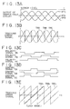
- the comparators 82a, 82b, 82c detect the polarities of the tracking error signals TRA, TRB, TRC respectively as shown in Fig. 13C, then generates polarity signals PA, PB, PC which become "1" at a positive level for example, and supply such signals to the logic calculator 83. Subsequently the logic calculator 83 executes undermentioned calculations of Eqs. (1) to (3) to generate control signals CA, CB, CC of which phases are mutually different by 120° as shown in Fig. 13D.
- the multiplexer 81 is controlled by the control signals CA, CB, CC in such a manner as to select the tracking error signal TRA when the control signal CA is “1", or to select the tracking error signal TRB when the control signal CB is “1", or to select the tracking error signal TRC when the control signal CC is "1".
- CA PC ⁇ INV (PB) (1)
- CB PA ⁇ INV (PC) (2)
- CC PB ⁇ INV (PA) (3)
- " ⁇ " and "INV ( )" denote a logical product and a negative logic, respectively.
- the multiplexer 81 generates a tracking error signal where, as indicated by a solid line in Fig. 13B, the three-phase tracking error signals TRA, TRB, TRC having mutually different phases are periodically switched.
- the tracking error signal thus outputted from the multiplexer 81 is processed in the servo loop for phase compensation and then is supplied to the actuator incorporated in the optical head, so that the objective lens 23 is displaced by the actuator in the radial direction of the optical disc 1 in a manner to reduce the tracking error signal to zero.
- the intermediate position between the paired adjacent tracks is regarded as a tracking center, and a scan for playback is executed to thereby read the 16-value pattern data from the paired tracks.
- wobble pits 11 are provided as data B or data C, it is possible, by utilizing such wobble pits 11, to perform tracking in a detrack state with a slight deviation from the tracking center.
- servo pits 11S composed of the aforementioned nonwobble pits are provided as a portion of the reference data or separately therefrom, and servo pits 11Sw+, 11Sw- are formed of wobble pits in the servo area SA.
- servo pits 11Sw+ are provided at positions PS A+ , PS B+ , PS C+ by using the patterns P6, P8, P14 of the wobble pits having a deviation + ⁇ to represent the data B.
- servo pits 11Sw- are provided at positions PS A- , PS B- , PS C- by using the patterns P11, P12, P15 of wobble pits having a deviation - ⁇ to represent the data C.
- tracking control is performed with a deviation - ⁇ from the original tracking center indicated by a one-dot chained line.
- tracking control is performed with a deviation - ⁇ from the original tracking center.
- data A is read as data B so that the actual pattern P1 (A1, A2) is discriminated as the pattern P6 (B1, B2). And the actual pattern P3 (A1, C2) is discriminated as the pattern P5 (B1, A2) since data A is read as data B, and data C is read as data A.
- a defocus state for example, there may occur a case where the modulation degree is lowered (with the level of pattern P10 changed from 6 to 5) or is raised (with the level of pattern P7 changed from 2 to 3) while the push-pull signal of patterns P1, P7, P16, P10 remains unchanged.
- a data map can be formed by + ⁇ F and - ⁇ F defocus states, which may be utilized similarly to the above.
- a scan for playback is executed as denoted by R1, R2 .... and so forth in Fig. 3A, whereby each track is scanned twice for playback.
- the operation for verification can be performed with reference to the data obtained by the preceding scan.
- 4-value data reproduced from the track #2 by a scan R1 is stored temporarily in the 16-value converter 31c. And in response to input of next 4-value data reproduced from the track #2 by a following scan R2, such input data is compared with the stored data obtained by the preceding scan R1. And after verifying a coincidence therebetween, the reproduced data of the track #2 is completely decided.
- the reproduced data of the track #3 is decided on the basis of the data obtained from the track #3 by a scan R2 and the data obtained therefrom by a following scan R3. After verifying proper extraction of the stored data in this manner, the 16-value data is reproduced according to the data map. Such verification is effective to diminish or eliminate any data reproduction error.
- any harmful influence of the crosstalk from the adjacent track #3 can be reduced by executing a scan R1 in a + ⁇ detrack state (using the + ⁇ detrack data maps).
- any harmful influence of the crosstalk from the adjacent track #1 can be reduced by executing a scan R2 in a - ⁇ detrack state (using the - ⁇ detrack data map).
- the embodiment described hereinabove is concerned with an exemplary case of setting deviations ⁇ relative to wobble pits.
- the signal-to-noise ratio is sufficiently high, other wobble pits having deviations ⁇ and ⁇ may also be provided in addition to the wobble pits having the deviations ⁇ .
- the data represented on the track comprises, for example, 8 values including a nonwobble pit (the said data A), ⁇ wobble pits (the said data B, C), a mirror portion M, ⁇ wobble pits (data D, E) and ⁇ wobble pits (the said data F, G).
- data are recorded in the shape of embossed pits.
- the present invention is applicable also to another type where data are represented by grooves.
- three or more values are represented by the use of wobbling grooves having deviations of ⁇ and so forth from an on-track groove.
- the recording medium is not limited merely to an optical disc alone, and the present invention is applicable to any of card-like recording media as well.
Landscapes
- Physics & Mathematics (AREA)
- Optics & Photonics (AREA)
- Optical Recording Or Reproduction (AREA)
Applications Claiming Priority (3)
| Application Number | Priority Date | Filing Date | Title |
|---|---|---|---|
| JP17888792 | 1992-06-15 | ||
| JP178887/92 | 1992-06-15 | ||
| JP17888792A JP3166322B2 (ja) | 1992-06-15 | 1992-06-15 | 再生方法、再生装置 |
Publications (3)
| Publication Number | Publication Date |
|---|---|
| EP0574886A2 true EP0574886A2 (fr) | 1993-12-22 |
| EP0574886A3 EP0574886A3 (fr) | 1994-01-26 |
| EP0574886B1 EP0574886B1 (fr) | 2000-11-02 |
Family
ID=16056439
Family Applications (1)
| Application Number | Title | Priority Date | Filing Date |
|---|---|---|---|
| EP93109547A Expired - Lifetime EP0574886B1 (fr) | 1992-06-15 | 1993-06-15 | Milieu d'enregistrement et méthode de réproduction pour ceci |
Country Status (4)
| Country | Link |
|---|---|
| US (3) | US5416766A (fr) |
| EP (1) | EP0574886B1 (fr) |
| JP (1) | JP3166322B2 (fr) |
| DE (1) | DE69329605T2 (fr) |
Cited By (5)
| Publication number | Priority date | Publication date | Assignee | Title |
|---|---|---|---|---|
| EP0696796A1 (fr) * | 1994-08-10 | 1996-02-14 | Nippon Telegraph And Telephone Corporation | Dispositif et procédé pour la lecture des données utilisant des faisceaux optiques |
| EP0801382A2 (fr) * | 1996-04-11 | 1997-10-15 | Matsushita Electric Industrial Co., Ltd. | Appareil et méthode d'enregistrement et/ou de reproduction optique d'information |
| WO1998049679A2 (fr) * | 1997-04-25 | 1998-11-05 | Koninklijke Philips Electronics N.V. | Appareil et unite de detection permettant de balayer un support d'enregistrement pour lecture optique |
| WO2000034947A1 (fr) * | 1998-12-07 | 2000-06-15 | Sony Corporation | Support d'enregistrement optique, dispositif et procede d'enregistrement de support d'enregistrement optique, et dispositif et procede de reproduction de support d'enregistrement optique |
| WO2006043356A1 (fr) | 2004-10-19 | 2006-04-27 | Matsushita Electric Industrial Co., Ltd. | Procede d’enregistrement/de reproduction de support d’enregistrement optique, support d’enregistrement optique et dispositif d’enregistrement/de reproduction pour ce meme support |
Families Citing this family (27)
| Publication number | Priority date | Publication date | Assignee | Title |
|---|---|---|---|---|
| EP0829855B1 (fr) * | 1992-02-19 | 2001-11-14 | Sony Corporation | Support d'enregistrement optique, méthode d'enregistrement et de reproduction, et méthode pour produire des signaux d'erreur de suivi |
| US5633854A (en) * | 1992-02-19 | 1997-05-27 | Sony Corporation | Methods and apparatus for reproducing data recorded on an optical recording medium |
| JP3166322B2 (ja) * | 1992-06-15 | 2001-05-14 | ソニー株式会社 | 再生方法、再生装置 |
| US5638354A (en) * | 1993-07-16 | 1997-06-10 | Ricoh Company, Ltd. | Optical information recording medium |
| JP3240762B2 (ja) * | 1993-07-26 | 2001-12-25 | ソニー株式会社 | 光記録媒体の再生方法及び再生装置 |
| US5654948A (en) * | 1993-09-07 | 1997-08-05 | Sony Corporation | Disc apparatus for recording/reproducing with zone constant angular velocity |
| US5602690A (en) * | 1994-01-20 | 1997-02-11 | Sony Corporation | Clock signal generating device and clock signal generating method |
| JPH07254156A (ja) * | 1994-03-15 | 1995-10-03 | Pioneer Electron Corp | 光ディスク及び光ディスク再生装置の信号処理回路 |
| WO1995031806A1 (fr) * | 1994-05-17 | 1995-11-23 | Sony Corporation | Servomecanisme de poursuite de piste et dispositif de comptage de pistes |
| DE69528574T2 (de) * | 1994-08-25 | 2003-05-22 | Sony Corp | Optische platte und optisches plattenantriebsgerät |
| US6215758B1 (en) | 1996-10-04 | 2001-04-10 | Sony Corporation | Recording medium |
| US6023447A (en) * | 1996-07-05 | 2000-02-08 | Sony Corporation | Optical disk, recording method and apparatus for canceling intercode interference |
| JP3511464B2 (ja) * | 1997-05-08 | 2004-03-29 | パイオニア株式会社 | トラッキングエラー信号生成方法及びトラッキングエラー信号生成装置 |
| JP3833787B2 (ja) * | 1997-08-07 | 2006-10-18 | 富士通株式会社 | 基地局の送受信装置 |
| RU2248622C2 (ru) * | 1998-12-07 | 2005-03-20 | Сони Корпорейшн | Оптический носитель записи, способ и устройство записи для оптического носителя записи, а также способ и устройство воспроизведения для оптического носителя записи |
| JP3690177B2 (ja) | 1999-02-22 | 2005-08-31 | 三菱電機株式会社 | ディスク装置 |
| JP4419041B2 (ja) * | 2001-06-19 | 2010-02-24 | ソニー株式会社 | 光信号記録装置及び光信号記録方法 |
| TW200403635A (en) * | 2002-07-24 | 2004-03-01 | Matsushita Electric Ind Co Ltd | Optical disc drive and method of controlling write operation performed by optical disc drive |
| US20070242593A1 (en) * | 2003-11-05 | 2007-10-18 | Koninklijke Philips Electronics N.V. | Method and device for reading information from optical disc |
| EP1745475A1 (fr) * | 2004-04-30 | 2007-01-24 | Koninklijke Philips Electronics N.V. | Dispositif de lecture/ecriture optique dote d'un faisceau de suivi de mise au point specialise |
| KR20070029791A (ko) * | 2004-06-03 | 2007-03-14 | 코닌클리케 필립스 일렉트로닉스 엔.브이. | 롬 마크를 포함하는 기록매체와 이 롬 마크를 검색하는재생장치 |
| KR100694102B1 (ko) * | 2005-04-11 | 2007-03-12 | 삼성전자주식회사 | 다층 기록 매체 및 그 기록 및/또는 재생을 위한 광픽업장치 |
| JP2012243363A (ja) * | 2011-05-20 | 2012-12-10 | Sony Corp | 再生方法、再生装置 |
| US10134438B2 (en) | 2013-06-28 | 2018-11-20 | Sony Corporation | Optical medium reproduction apparatus and method of reproducing optical medium |
| JP6167918B2 (ja) | 2013-08-14 | 2017-07-26 | ソニー株式会社 | 光媒体再生装置および光媒体再生方法 |
| WO2015022767A1 (fr) | 2013-08-14 | 2015-02-19 | ソニー株式会社 | Dispositif de reproduction de support optique et procédé de reproduction de support optique |
| EP3044724B1 (fr) * | 2013-10-29 | 2022-09-07 | Sony Corporation of America | Lecteur organisé en rangée et lecture en rangée de supports optiques |
Citations (7)
| Publication number | Priority date | Publication date | Assignee | Title |
|---|---|---|---|---|
| EP0037673A1 (fr) * | 1980-04-03 | 1981-10-14 | AMP INCORPORATED (a New Jersey corporation) | Mécanisme unitaire pour outils |
| EP0111006A1 (fr) * | 1982-05-31 | 1984-06-20 | Sony Corporation | Generateur de signaux de commande de tete optique |
| JPS59207433A (ja) * | 1983-05-12 | 1984-11-24 | Sony Corp | 高密度記録再生方式 |
| JPH01134728A (ja) * | 1987-11-20 | 1989-05-26 | Nec Corp | 光ディスク装置の記録読出方式 |
| EP0376626A2 (fr) * | 1988-12-27 | 1990-07-04 | Canon Kabushiki Kaisha | Support d'enregistrement d'information optique avec partie séparatrice entre les pistes d'information |
| EP0463728A2 (fr) * | 1990-06-29 | 1992-01-02 | Quantum Corporation | Augmentation de la densité d'emmagasinage des milieux d'emmagasinage d'informations |
| EP0502582A1 (fr) * | 1991-03-07 | 1992-09-09 | Koninklijke Philips Electronics N.V. | Système de lecture d'information ainsi que support d'enregistrement et dispositif de lecture destinés à être utilisés dans un tel système |
Family Cites Families (6)
| Publication number | Priority date | Publication date | Assignee | Title |
|---|---|---|---|---|
| CA1258909A (fr) * | 1985-03-29 | 1989-08-29 | Hideki Hosoya | Support d'enregistrement optique et methode d'enregistrement et de lecture d'informations sur ce support |
| JP2612329B2 (ja) * | 1988-12-27 | 1997-05-21 | シャープ株式会社 | 光メモリ素子並びに光メモリ再生装置 |
| US5193081A (en) * | 1989-02-28 | 1993-03-09 | Kabushiki Kaisha Toshiba | Track-accessing controller for optical disks |
| US5214629A (en) * | 1990-02-27 | 1993-05-25 | Hitachi Maxell, Ltd. | Optical disc having a high-speed access capability and reading apparatus therefor |
| JPH05242512A (ja) * | 1991-12-19 | 1993-09-21 | Matsushita Electric Ind Co Ltd | 光ディスク装置 |
| JP3166322B2 (ja) * | 1992-06-15 | 2001-05-14 | ソニー株式会社 | 再生方法、再生装置 |
-
1992
- 1992-06-15 JP JP17888792A patent/JP3166322B2/ja not_active Expired - Fee Related
-
1993
- 1993-06-11 US US08/075,828 patent/US5416766A/en not_active Expired - Fee Related
- 1993-06-15 EP EP93109547A patent/EP0574886B1/fr not_active Expired - Lifetime
- 1993-06-15 DE DE69329605T patent/DE69329605T2/de not_active Expired - Fee Related
-
1994
- 1994-09-15 US US08/306,457 patent/US5553046A/en not_active Expired - Fee Related
- 1994-09-15 US US08/306,651 patent/US5557600A/en not_active Expired - Fee Related
Patent Citations (7)
| Publication number | Priority date | Publication date | Assignee | Title |
|---|---|---|---|---|
| EP0037673A1 (fr) * | 1980-04-03 | 1981-10-14 | AMP INCORPORATED (a New Jersey corporation) | Mécanisme unitaire pour outils |
| EP0111006A1 (fr) * | 1982-05-31 | 1984-06-20 | Sony Corporation | Generateur de signaux de commande de tete optique |
| JPS59207433A (ja) * | 1983-05-12 | 1984-11-24 | Sony Corp | 高密度記録再生方式 |
| JPH01134728A (ja) * | 1987-11-20 | 1989-05-26 | Nec Corp | 光ディスク装置の記録読出方式 |
| EP0376626A2 (fr) * | 1988-12-27 | 1990-07-04 | Canon Kabushiki Kaisha | Support d'enregistrement d'information optique avec partie séparatrice entre les pistes d'information |
| EP0463728A2 (fr) * | 1990-06-29 | 1992-01-02 | Quantum Corporation | Augmentation de la densité d'emmagasinage des milieux d'emmagasinage d'informations |
| EP0502582A1 (fr) * | 1991-03-07 | 1992-09-09 | Koninklijke Philips Electronics N.V. | Système de lecture d'information ainsi que support d'enregistrement et dispositif de lecture destinés à être utilisés dans un tel système |
Non-Patent Citations (2)
| Title |
|---|
| PATENT ABSTRACTS OF JAPAN vol. 13, no. 387 (P-924)28 August 1989 & JP-A-01 134 728 (NEC CORP.) * |
| PATENT ABSTRACTS OF JAPAN vol. 9, no. 76 (P-346)5 April 1985 & JP-A-59 207 433 (SONY KK) * |
Cited By (13)
| Publication number | Priority date | Publication date | Assignee | Title |
|---|---|---|---|---|
| EP0696796A1 (fr) * | 1994-08-10 | 1996-02-14 | Nippon Telegraph And Telephone Corporation | Dispositif et procédé pour la lecture des données utilisant des faisceaux optiques |
| US5619487A (en) * | 1994-08-10 | 1997-04-08 | Nippon Telegraph And Telephone Corporation | Optical data readout with two beams on three tracks |
| US6044051A (en) * | 1996-04-11 | 2000-03-28 | Matsushita Electric Industrial Co., Ltd. | Optical information recording/reproducing device and method for recording, reproducing and erasing information on an optical information recording medium utilizing light beam radiation |
| EP0801382A3 (fr) * | 1996-04-11 | 1998-07-22 | Matsushita Electric Industrial Co., Ltd. | Appareil et méthode d'enregistrement et/ou de reproduction optique d'information |
| EP0801382A2 (fr) * | 1996-04-11 | 1997-10-15 | Matsushita Electric Industrial Co., Ltd. | Appareil et méthode d'enregistrement et/ou de reproduction optique d'information |
| WO1998049679A2 (fr) * | 1997-04-25 | 1998-11-05 | Koninklijke Philips Electronics N.V. | Appareil et unite de detection permettant de balayer un support d'enregistrement pour lecture optique |
| WO1998049679A3 (fr) * | 1997-04-25 | 1999-02-04 | Koninkl Philips Electronics Nv | Appareil et unite de detection permettant de balayer un support d'enregistrement pour lecture optique |
| WO2000034947A1 (fr) * | 1998-12-07 | 2000-06-15 | Sony Corporation | Support d'enregistrement optique, dispositif et procede d'enregistrement de support d'enregistrement optique, et dispositif et procede de reproduction de support d'enregistrement optique |
| US6801490B1 (en) * | 1998-12-07 | 2004-10-05 | Sony Corporation | Optical recording medium, device and method for recording optical recording medium, and device and method for reproducing optical recorded medium |
| WO2006043356A1 (fr) | 2004-10-19 | 2006-04-27 | Matsushita Electric Industrial Co., Ltd. | Procede d’enregistrement/de reproduction de support d’enregistrement optique, support d’enregistrement optique et dispositif d’enregistrement/de reproduction pour ce meme support |
| EP1806744A1 (fr) * | 2004-10-19 | 2007-07-11 | Matsushita Electric Industrial Co., Ltd. | Procede d"enregistrement/de reproduction de support d"enregistrement optique, support d"enregistrement optique et dispositif d"enregistrement/de reproduction pour ce meme support |
| EP1806744A4 (fr) * | 2004-10-19 | 2009-08-05 | Panasonic Corp | Procede d"enregistrement/de reproduction de support d"enregistrement optique, support d"enregistrement optique et dispositif d"enregistrement/de reproduction pour ce meme support |
| US7701813B2 (en) | 2004-10-19 | 2010-04-20 | Panasonic Corporation | Method for recording to and reproducing from an optical recording medium, optical recording medium, and recording and reproduction apparatus for the same |
Also Published As
| Publication number | Publication date |
|---|---|
| JPH05347026A (ja) | 1993-12-27 |
| DE69329605D1 (de) | 2000-12-07 |
| US5553046A (en) | 1996-09-03 |
| US5416766A (en) | 1995-05-16 |
| DE69329605T2 (de) | 2001-03-01 |
| EP0574886A3 (fr) | 1994-01-26 |
| JP3166322B2 (ja) | 2001-05-14 |
| US5557600A (en) | 1996-09-17 |
| EP0574886B1 (fr) | 2000-11-02 |
Similar Documents
| Publication | Publication Date | Title |
|---|---|---|
| EP0574886B1 (fr) | Milieu d'enregistrement et méthode de réproduction pour ceci | |
| US4507763A (en) | Optical information recording and/or reproducing apparatus and optical record medium for use in such apparatus | |
| US6493296B1 (en) | Optical disc inclination detecting method, optical pickup device, and optical disc device | |
| JP3033864B2 (ja) | 情報記録方法及びその情報再生装置 | |
| US5402411A (en) | Constant amplitude of tracking error signals generated from a head guide track and a performed track | |
| EP0570235A2 (fr) | Disque optique | |
| JPH06103537B2 (ja) | 情報媒体のトラック走査用光ビームのフォーカシング制御信号生成装置及び方法 | |
| US5557602A (en) | Optical recording medium, recording and reproducing method and tracking error generating method | |
| US5684783A (en) | Reproducing apparatus having a detector for simultaneously scanning adjacent tracks of an optical recording medium | |
| JP3225668B2 (ja) | 光記録媒体、その記録方法および再生方法 | |
| JP2001307359A (ja) | 光ディスク傾き検出方法、光学ピックアップ装置および光ディスク装置 | |
| JP3196440B2 (ja) | 光記録媒体のデータ記録方法、光記録媒体のデータ記録装置及び光記録媒体のデータ再生装置 | |
| JP3227803B2 (ja) | 光記録媒体の再生方法 | |
| JPH1186310A (ja) | 光ディスク装置 | |
| JPH06333246A (ja) | 光記録媒体のデータ記録方法及び光記録媒体のデータ記録装置 | |
| JPH05342586A (ja) | 情報記録媒体再生装置 | |
| JPH10162384A (ja) | ランドグルーブ位置検出方式及び方法 | |
| JPH1186424A (ja) | 光ディスク装置の制御装置およびその制御方法 | |
| JPH0473222B2 (fr) | ||
| JP2000155963A (ja) | 光学ピックアップ装置およびこれを具備する光記録再生装置 | |
| JPS62125541A (ja) | 光ピツクアツプヘツドの回折格子取付位置調整方法 | |
| JPH0991702A (ja) | 光学的情報記録装置 | |
| JPH0478073A (ja) | トラック間位置検出方式 | |
| JPH0636339A (ja) | 光学式再生装置 |
Legal Events
| Date | Code | Title | Description |
|---|---|---|---|
| PUAI | Public reference made under article 153(3) epc to a published international application that has entered the european phase |
Free format text: ORIGINAL CODE: 0009012 |
|
| PUAL | Search report despatched |
Free format text: ORIGINAL CODE: 0009013 |
|
| AK | Designated contracting states |
Kind code of ref document: A2 Designated state(s): DE FR GB |
|
| AK | Designated contracting states |
Kind code of ref document: A3 Designated state(s): DE FR GB |
|
| 17P | Request for examination filed |
Effective date: 19940624 |
|
| 17Q | First examination report despatched |
Effective date: 19960930 |
|
| GRAG | Despatch of communication of intention to grant |
Free format text: ORIGINAL CODE: EPIDOS AGRA |
|
| GRAG | Despatch of communication of intention to grant |
Free format text: ORIGINAL CODE: EPIDOS AGRA |
|
| GRAH | Despatch of communication of intention to grant a patent |
Free format text: ORIGINAL CODE: EPIDOS IGRA |
|
| GRAH | Despatch of communication of intention to grant a patent |
Free format text: ORIGINAL CODE: EPIDOS IGRA |
|
| GRAA | (expected) grant |
Free format text: ORIGINAL CODE: 0009210 |
|
| AK | Designated contracting states |
Kind code of ref document: B1 Designated state(s): DE FR GB |
|
| REF | Corresponds to: |
Ref document number: 69329605 Country of ref document: DE Date of ref document: 20001207 |
|
| ET | Fr: translation filed | ||
| PGFP | Annual fee paid to national office [announced via postgrant information from national office to epo] |
Ref country code: FR Payment date: 20010611 Year of fee payment: 9 Ref country code: DE Payment date: 20010611 Year of fee payment: 9 |
|
| PGFP | Annual fee paid to national office [announced via postgrant information from national office to epo] |
Ref country code: GB Payment date: 20010613 Year of fee payment: 9 |
|
| PLBE | No opposition filed within time limit |
Free format text: ORIGINAL CODE: 0009261 |
|
| STAA | Information on the status of an ep patent application or granted ep patent |
Free format text: STATUS: NO OPPOSITION FILED WITHIN TIME LIMIT |
|
| 26N | No opposition filed | ||
| REG | Reference to a national code |
Ref country code: GB Ref legal event code: IF02 |
|
| PG25 | Lapsed in a contracting state [announced via postgrant information from national office to epo] |
Ref country code: GB Free format text: LAPSE BECAUSE OF NON-PAYMENT OF DUE FEES Effective date: 20020615 |
|
| PG25 | Lapsed in a contracting state [announced via postgrant information from national office to epo] |
Ref country code: DE Free format text: LAPSE BECAUSE OF NON-PAYMENT OF DUE FEES Effective date: 20030101 |
|
| GBPC | Gb: european patent ceased through non-payment of renewal fee |
Effective date: 20020615 |
|
| PG25 | Lapsed in a contracting state [announced via postgrant information from national office to epo] |
Ref country code: FR Free format text: LAPSE BECAUSE OF NON-PAYMENT OF DUE FEES Effective date: 20030228 |
|
| REG | Reference to a national code |
Ref country code: FR Ref legal event code: ST |