EP0569913B1 - Connection path selection method for cross-connect communications networks - Google Patents
Connection path selection method for cross-connect communications networks Download PDFInfo
- Publication number
- EP0569913B1 EP0569913B1 EP93107586A EP93107586A EP0569913B1 EP 0569913 B1 EP0569913 B1 EP 0569913B1 EP 93107586 A EP93107586 A EP 93107586A EP 93107586 A EP93107586 A EP 93107586A EP 0569913 B1 EP0569913 B1 EP 0569913B1
- Authority
- EP
- European Patent Office
- Prior art keywords
- input
- stage
- output
- switch
- idle
- Prior art date
- Legal status (The legal status is an assumption and is not a legal conclusion. Google has not performed a legal analysis and makes no representation as to the accuracy of the status listed.)
- Expired - Lifetime
Links
- 238000004891 communication Methods 0.000 title claims abstract description 17
- 238000010187 selection method Methods 0.000 title description 3
- 239000011159 matrix material Substances 0.000 claims abstract description 134
- 238000000034 method Methods 0.000 claims abstract description 85
- 238000005086 pumping Methods 0.000 claims abstract description 8
- 230000008707 rearrangement Effects 0.000 abstract description 67
- 230000008569 process Effects 0.000 abstract description 22
- 238000003491 array Methods 0.000 abstract description 6
- 238000013479 data entry Methods 0.000 description 5
- 230000000903 blocking effect Effects 0.000 description 4
- 230000009471 action Effects 0.000 description 3
- 230000000694 effects Effects 0.000 description 3
- 238000012360 testing method Methods 0.000 description 3
- 108010002352 Interleukin-1 Proteins 0.000 description 2
- 230000001934 delay Effects 0.000 description 2
- 238000013461 design Methods 0.000 description 2
- 230000006870 function Effects 0.000 description 2
- 238000012986 modification Methods 0.000 description 2
- 230000004048 modification Effects 0.000 description 2
- 230000009286 beneficial effect Effects 0.000 description 1
- 238000006243 chemical reaction Methods 0.000 description 1
- 125000004122 cyclic group Chemical group 0.000 description 1
- 239000004744 fabric Substances 0.000 description 1
- 238000004519 manufacturing process Methods 0.000 description 1
- 238000012545 processing Methods 0.000 description 1
- 230000004044 response Effects 0.000 description 1
- 238000005096 rolling process Methods 0.000 description 1
- 230000009466 transformation Effects 0.000 description 1
Images


Classifications
-
- H—ELECTRICITY
- H04—ELECTRIC COMMUNICATION TECHNIQUE
- H04L—TRANSMISSION OF DIGITAL INFORMATION, e.g. TELEGRAPHIC COMMUNICATION
- H04L49/00—Packet switching elements
- H04L49/25—Routing or path finding in a switch fabric
-
- H—ELECTRICITY
- H04—ELECTRIC COMMUNICATION TECHNIQUE
- H04L—TRANSMISSION OF DIGITAL INFORMATION, e.g. TELEGRAPHIC COMMUNICATION
- H04L12/00—Data switching networks
- H04L12/54—Store-and-forward switching systems
- H04L12/56—Packet switching systems
- H04L12/5601—Transfer mode dependent, e.g. ATM
-
- H—ELECTRICITY
- H04—ELECTRIC COMMUNICATION TECHNIQUE
- H04L—TRANSMISSION OF DIGITAL INFORMATION, e.g. TELEGRAPHIC COMMUNICATION
- H04L49/00—Packet switching elements
- H04L49/10—Packet switching elements characterised by the switching fabric construction
- H04L49/101—Packet switching elements characterised by the switching fabric construction using crossbar or matrix
-
- H—ELECTRICITY
- H04—ELECTRIC COMMUNICATION TECHNIQUE
- H04L—TRANSMISSION OF DIGITAL INFORMATION, e.g. TELEGRAPHIC COMMUNICATION
- H04L49/00—Packet switching elements
- H04L49/10—Packet switching elements characterised by the switching fabric construction
- H04L49/104—Asynchronous transfer mode [ATM] switching fabrics
- H04L49/105—ATM switching elements
- H04L49/106—ATM switching elements using space switching, e.g. crossbar or matrix
-
- H—ELECTRICITY
- H04—ELECTRIC COMMUNICATION TECHNIQUE
- H04L—TRANSMISSION OF DIGITAL INFORMATION, e.g. TELEGRAPHIC COMMUNICATION
- H04L49/00—Packet switching elements
- H04L49/15—Interconnection of switching modules
- H04L49/1553—Interconnection of ATM switching modules, e.g. ATM switching fabrics
- H04L49/1576—Crossbar or matrix
-
- H—ELECTRICITY
- H04—ELECTRIC COMMUNICATION TECHNIQUE
- H04L—TRANSMISSION OF DIGITAL INFORMATION, e.g. TELEGRAPHIC COMMUNICATION
- H04L49/00—Packet switching elements
- H04L49/25—Routing or path finding in a switch fabric
- H04L49/256—Routing or path finding in ATM switching fabrics
-
- H—ELECTRICITY
- H04—ELECTRIC COMMUNICATION TECHNIQUE
- H04Q—SELECTING
- H04Q3/00—Selecting arrangements
- H04Q3/64—Distributing or queueing
- H04Q3/68—Grouping or interlacing selector groups or stages
-
- H—ELECTRICITY
- H04—ELECTRIC COMMUNICATION TECHNIQUE
- H04Q—SELECTING
- H04Q3/00—Selecting arrangements
- H04Q3/64—Distributing or queueing
- H04Q3/68—Grouping or interlacing selector groups or stages
- H04Q3/685—Circuit arrangements therefor
-
- H—ELECTRICITY
- H04—ELECTRIC COMMUNICATION TECHNIQUE
- H04J—MULTIPLEX COMMUNICATION
- H04J2203/00—Aspects of optical multiplex systems other than those covered by H04J14/05 and H04J14/07
- H04J2203/0001—Provisions for broadband connections in integrated services digital network using frames of the Optical Transport Network [OTN] or using synchronous transfer mode [STM], e.g. SONET, SDH
- H04J2203/0003—Switching fabrics, e.g. transport network, control network
- H04J2203/0012—Switching modules and their interconnections
-
- H—ELECTRICITY
- H04—ELECTRIC COMMUNICATION TECHNIQUE
- H04L—TRANSMISSION OF DIGITAL INFORMATION, e.g. TELEGRAPHIC COMMUNICATION
- H04L12/00—Data switching networks
- H04L12/54—Store-and-forward switching systems
- H04L12/56—Packet switching systems
- H04L12/5601—Transfer mode dependent, e.g. ATM
- H04L2012/5625—Operations, administration and maintenance [OAM]
- H04L2012/5627—Fault tolerance and recovery
-
- H—ELECTRICITY
- H04—ELECTRIC COMMUNICATION TECHNIQUE
- H04Q—SELECTING
- H04Q2213/00—Indexing scheme relating to selecting arrangements in general and for multiplex systems
- H04Q2213/1302—Relay switches
-
- H—ELECTRICITY
- H04—ELECTRIC COMMUNICATION TECHNIQUE
- H04Q—SELECTING
- H04Q2213/00—Indexing scheme relating to selecting arrangements in general and for multiplex systems
- H04Q2213/1304—Coordinate switches, crossbar, 4/2 with relays, coupling field
-
- H—ELECTRICITY
- H04—ELECTRIC COMMUNICATION TECHNIQUE
- H04Q—SELECTING
- H04Q2213/00—Indexing scheme relating to selecting arrangements in general and for multiplex systems
- H04Q2213/13056—Routines, finite state machines
-
- H—ELECTRICITY
- H04—ELECTRIC COMMUNICATION TECHNIQUE
- H04Q—SELECTING
- H04Q2213/00—Indexing scheme relating to selecting arrangements in general and for multiplex systems
- H04Q2213/13076—Distributing frame, MDF, cross-connect switch
-
- H—ELECTRICITY
- H04—ELECTRIC COMMUNICATION TECHNIQUE
- H04Q—SELECTING
- H04Q2213/00—Indexing scheme relating to selecting arrangements in general and for multiplex systems
- H04Q2213/13141—Hunting for free outlet, circuit or channel
-
- H—ELECTRICITY
- H04—ELECTRIC COMMUNICATION TECHNIQUE
- H04Q—SELECTING
- H04Q2213/00—Indexing scheme relating to selecting arrangements in general and for multiplex systems
- H04Q2213/13144—Searching path through number of switching stages or nodes, e.g. revertive blocking
-
- H—ELECTRICITY
- H04—ELECTRIC COMMUNICATION TECHNIQUE
- H04Q—SELECTING
- H04Q2213/00—Indexing scheme relating to selecting arrangements in general and for multiplex systems
- H04Q2213/13146—Rerouting upon blocking/overload, rearrangement
-
- H—ELECTRICITY
- H04—ELECTRIC COMMUNICATION TECHNIQUE
- H04Q—SELECTING
- H04Q2213/00—Indexing scheme relating to selecting arrangements in general and for multiplex systems
- H04Q2213/1334—Configuration within the switch
-
- H—ELECTRICITY
- H04—ELECTRIC COMMUNICATION TECHNIQUE
- H04Q—SELECTING
- H04Q2213/00—Indexing scheme relating to selecting arrangements in general and for multiplex systems
- H04Q2213/13341—Connections within the switch
Definitions
- the present invention is concerned generally with electronics and more specifically with communications systems. Even more specifically, the invention is concerned with a method and system that finds an optimal path through a communications matrix using a set of matrices or arrays that describe the status of the communication matrix and include an input stage array, a center stage array, and an output stage array, as well as arrays representing idle links from the input stage switches to the center stage switches and the idle links from the center stage switches to the output stage switches.
- Digital cross-connect communications network devices such as the 1631 SX manufactured by Alcatel Network Systems, Inc.
- 1631 SX manufactured by Alcatel Network Systems, Inc.
- Known designs for such cross-connect devices make use of matrices to connect the input gates to the output gates.
- designers seek to minimize the number of cross-connects in the matrix This objective becomes more complicated as market demands for communications services increase.
- the devices must service more and more input and output signals.
- a rearrangeable matrix One matrix configuration that uses a minimal number of matrix cross-connects for a given number of input gates and output gates and that provides a potentially optimal solution is known as a "rearrangeable" matrix.
- the number of center stage switches must equal or exceed the number of input gates on each switch of the matrix.
- a rearrangeable matrix there exists a set of conditions such that, although the device does not use all input gates and all output gates, an attempt to use an idle input gate and an output gate is prohibited because existing connections block the signal flow through the matrix. This may happen, for example, if existing connections already occupy at least one link in every possible path between the input and output gates in question.
- rearrangeable In a rearrangeable network, it is always possible to unblock a flow path from an idle input gate to an idle output gate by moving existing connections in the network.
- a data switch unit which comprises communication port adapter, a switch matrix and a central controller for handling connection requests from a first port through the switch matrix to a second port.
- the central controller stores a NxN matrix secifying allowed connections.
- a network control arrangement for processing a plurality of connection requests.
- the arrangement comprises a network for interconnecting any of a plurality of inlets with a plurality of outlets. It further comprises a memory for storing busy idle information for network path components.
- the memory is read out to identify an idle path from a first network inlet to a first network outlet.After identifying an idle path, path components of the path are marked busy. However, before the path is marked busy, the memory is accessed to find an idle path from a second network inlet to a second network outlet.
- two or more path hunt operations can be performed in parallel.
- a packet switch that eliminates internal path conflicts by providing distributes intelligence in routing packets through the switch fabric.
- the switch has K input stage modules, K output stage modules and K center stage modules and for each incoming packet, an idle path through the network has to be assigned.
- a timeslot is partinioned in K minislots.
- Each minislot one path is assigned from each input stage module to one output stage module. From minislot to minislot, each output stage module is moved to the next input stage module in a cyclic manner.
- the present invention achieves this object with a minimal amount of additional circuitry and avoids the service delays and interruptions of known connection path selection methods and systems that cannot immediately select an optimal connection configuration.
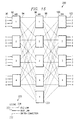
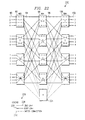
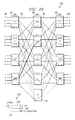
- FIGURE 1 a large matrix configuration is shown that provides for connection and test access for up to 1,024 DS3 ports (or equivalently, 32,678 DS1 ports) for the 1631 SX device.
- This is a five-stage, Time-Space-Space-Space-Time (TSSST)-division multiplexed connecting matrix network 50.
- Matrix configuration 50 includes time stage 52 that through connections 54 connects to three center space stage (SSS) designated generally by reference numeral 56.
- Three center space stage SSS 56 connects through output line 58 to output time stage 60.
- the network 50 includes a time-domain of time stages 52 and 60 and a space domain of three center space stage 56.
- FIGURE 1 illustrates logically the relationship between time stages 52 and 60 and the center space stages 56.
- Input time stage 52 uses 128 time slots per input 62.
- the time slots may be represented by the connections 64 between I/O shelf inputs 62 to each time slot 66 of matrix 56.
- Center space stage 56 includes 128 time slots 66, each of which time slot 66 includes a N(17,16,16) matrix.
- the number 17 of time slot matrix 66 represents the number of center stage switches; the first number 16 represents the number of inputs to each input stage switch, and the second 16 the number of input stage switches. (By symmetry, there are 16 outputs from each output stage switch and 16 output stage switches.)
- Output time stage 60 uses 128 time slot connections such as connection 68 for each matrix output 70 to an I/O shelf.
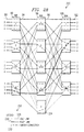
- center space stage 56 is represented mathematically as a three-stage connecting network cube of matrices 72 for each of which the symbol N(17,16,16) fully describes each of the matrices.
- N(17,16,16) matrix 72 there are in the example of FIGURE 2, 16 input switches such as input switch 74, for which each receives 16 input gates such as input gate 76.
- the total number of input gates 76 make up the I/O shelf-to-time slot connections 64 of FIGURE 1 for each time slot.
- From each input switch 74 go input switch-center switch connections 78 to the center switches such as center switch 80.
- each N(17,16,16) matrix 72 includes 17 center stage switches 80.
- Each output switch 84 provides 16 output gates such as output gate 86 that connect to I/O shelves such as I/O shelf 70 of FIGURE 1. The total number of output gates 86 make up the time slot-to-I/O shelf connections 68 of FIGURE 1 for each time slot.
- Connections are made between input gate 76 and output gate 86 immediately using the present connection technique.
- This technique sets up a connection by using a route through input switch 74, center switches 80 and output switches 84 that attempts to use the most used part of a matrix 72 first and the least used part of the matrix 72 last.
- the rearrangement process of the preferred embodiment encounters elements with the smallest number of pre-existing connections. This minimizes the volume of necessary computations for matrix rearrangement.
- the preferred embodiment uses a dedicated time slot when rearrangement is necessary in the time domain.
- the 128th time slot may be dedicated as an extra time slot for use during matrix 50 rearrangement.
- rearrangement uses a dedicated or extra center switch.
- center switch 17 may be the dedicated or extra center switch.
- the present connection technique automatically uses the dedicated or extra element (either the dedicated or extra time slot in the time domain or the dedicated center stage switch in the space domain) when a rearrangeably blocked condition exists.
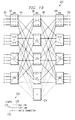
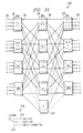
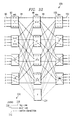
- FIGURE 3 illustrates that N(17,16,16) matrix 72 of FIGURE 2 may be generalized to matrix 88 for which the expression N(m,n,r) describes the configuration. Following the convention of the N(17,16,16) matrix 16, the generalized notation N(m,n,r) describes generalized matrix 88.
- m the number of rxr center stage switches (as well as the number of outputs from each nXm input stage and the number of inputs to each mXn output stage switch);
- n the number of inputs to each nXm input stage switch (as well as the number of outputs from each mXn output stage switch);
- r the number of nXm input stage switches (as well as the number of mXn output stage switches).
- matrix 88 m at least equals n+1. This limitation on m for a given n assures that there exists at least one extra center stage switch.
- generalized matrix 88 has n input gates 90 that connect to input switches, such as input switch 92, having m output connections 94.
- input switches such as input switch 92
- the input switch-to-center switch connections 94 connect to the rXr center switches such as center switch 96 where each center switch 96 receives r center switch connections 94 and provides r output connections 98.
- Each center switch-to-output switch connection 98 from center switches 96 connects to an output switch 100.
- Each output switch 100 receives m center switch-to-output switch connections 98 and outputs to n output gates such as output gate 102.
- Both the N(17,16,16) matrix 72 of FIGURE 2 and the N(m,n,r) matrix 88 of FIGURE 3 are said to be rearrangeable matrices if, respectively, for a given state of the matrix and any given idle pair of input gates 76 or 90 and output gates 86 or 102, the existing connections within the matrices may be reassigned to new paths, if necessary, to allow connecting the respective idle pairs.
- the matrices are rearrangeable if and only if m ⁇ n.
- the notation ⁇ (m,n,r) denotes the number of connections that must be rearranged in order to connect an idle pair of input and output gates.
- Paull's Method derives from the property that ⁇ (n,n,n) ⁇ n-1.
- N(n,n,n) matrix it is necessary to move at most n-1 connections to connect an idle input gate to an idle output gate.
- FIGURE 4 introduces notation to assist in understanding the preferred embodiment.
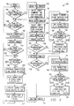
- FIGURE 5 provides a flow chart to illustrate the basic concepts of the immediate connect method and system of the present invention.
- FIGUREs 6 through 14 show an example of the operation of the method and system in the presence of a rearrangeably blocked condition of a matrix 72 of the three center stage space matrix 56.
- FIGUREs 15 through 34 that use a simplified N(5,4,4) rearrangeable matrix having the ability to perform immediate connection in a rearrangeably blocked condition.
- FIGURE 4 notation beneficial for understanding the present invention uses square matrix 110 to represent connections existing in a space domain matrix such as matrix 88 of FIGURE 3.
- Square matrix 110 has rows 112 designating input switches (such as input switch 92 of FIGURE 3) and columns 114 representing output switches (such as output switch 100 of FIGURE 3.)
- the simplified example of FIGURE 4 shows the number of rows 112 and columns 114 equals 8.
- FIGURE 5 could show a matrix having 16 rows representing input switches 74 and 16 columns representing output switches such as output switch 84.
- matrix position 116 there are m possible symbols that may appear. These m symbols correspond to the center switches such as center stage switch 96 of FIGURE 3.
- matrix position 116 may have m possible entries, one for each of the center stage switches 96 appearing in FIGURE 3.
- the ordered pair (3,1) denotes matrix position 116, where 3 is the row designation, i.e., row 3 having reference numeral 118, and 1 is the column position, i.e., column 1 having the reference numeral 120.
- the entry B (1 ⁇ B ⁇ m) in matrix position (3,1) corresponds to a connection from input switch 3 through intermediate switch B to output switch 1.
- each input switch 92 has only one connection 94 to each center switch 96, no two symbols in any row 112 may be the same.
- each output switch 100 has only one connection 98 from each center switch 96. No two symbols in any column 114 may be the same.
- a square matrix 110 satisfying these restrictions is said to be "legitimate" since it has only legitimate entries.
- flow chart 140 describes the steps and functions of the preferred embodiment of the present invention. Beginning at start step 142, the method is first to query, as query block 144 indicates, whether there is a pair of ports presented for connection. In the example of FIGURE 3, the step is to query whether there is an idle input gate 90 to connect to an idle output gate 102. If there is such a pair, then flow goes to block 146 to begin time domain connections. If there is not a pair of ports presented for connection, then flow goes to block 148 which is described below. At begin time domain step 146, flow goes to block 150 where the method selects the lowest numbered time slot available for connection. Then, at block 152 space domain operations begin for selecting the lowest numbered center stage input switch available for connection at step 154. Having selected the lowest numbered center stage for connection, the connections are made at block 156 and square matrix 110 or a similar status table designating connections is updated at block 158.
- a query of whether space rearrangement is required takes place. If so, then flow goes to block 162 where the step is to select two center stage switches for rearrangement.
- the step is to find the connections to be rearranged and, from the connections, the query at block 166 is of which path requires the least number of rearrangements. If the path X ⁇ A requires the least number of rearrangements, then program flow takes path 168. If X ⁇ B requires the least number of rearrangements, then program flow takes path 170. Regardless of which path program flow takes, at step 172 connections are rearranged, one at a time, using a "hitless roll.” The discussion below defines the term "hitless roll.” And flow returns to step 174 to end space domain operations. Note that if no space rearrangement was necessary, then flow from query block 160 goes directly to end space domain step at block 174.
- step 176 the question is whether time rearrangement is required. If so, then flow goes to step 178 at which point the method is to select two time slots for rearrangement. Then, at block 180, the step is to find connections to be arranged.
- a query occurs of which path requires the least number of rearrangements. If the X ⁇ A path requires the least number of rearrangements, flow goes along path 184. On the other hand, if the X ⁇ B path requires the least number of rearrangements, then flow follows path 186. The next step, regardless of whether program flow takes path 184 or 186, is to rearrange connections one-at-a-time, again using a hitless roll in the time domain at step 188. Program flow then goes to step 190 to end time-domain operations. Note that if query block 176 determines that no time rearrangement was required, flow proceeds directly to end time domain block 190.
- the method determines whether a "pack connections after a disconnect" function is enabled. If so, then flow goes to query 198 to examine whether a rearrangement is in progress. If so, then flow will loop via path 200 until rearrangement is no longer in process.
- FIGURE 5 shows disconnect as occurring subsequent to completing any necessary rearrangement
- the present method and system may process a disconnect request in parallel with rearrangement. Therefore, if the system of the present invention seeks to direct connections to the most used part of matrix first so as to pack calls after a disconnect, the rearrangement-in-progress query of block 198, prevents attempting to pack during rearrangement.
- next step is to determine the connections to the packed in the space at step 202.
- the next step of flow chart 140 is to pack connections in the space domain using a hitless roll at block 204.
- the step is to determine the connections to be packed in time, after which the connections are packed at block 206 in time using an automatically hitless roll.
- Program flow then returns to point 210 to continue the previously described operations of flow chart 140.
- Steps 162 and 178 execute Paull's Method to find the path requiring the fewest rearrangements. Specifically, with the blocked cell denoted (r 1 ,c 1 ) such as cell 121 of FIGURE 4, the method tests to find all symbol pairs (A,B) such that if A is in row 1, but not in column 1, and B is in column 1, but not in row 1. For given pairs of symbols, say (A,B), there are two possible rearrangement sequences, one of which will be shorter. Making this determination is part of step 16 in the space domain and step 182 in the time domain.
- the sequence "X ⁇ A” denotes a sequence that starts with an immediate connection through the dedicated element (e.g., center stage switch 17 of FIGURE 2 for the space domain and the time slot 128 in FIGURE 1 for the time domain) and ends with the blocked cell being assigned to element A.
- the sequence begins, for example, by starting with the blocked cell (r 1 ,c 1 ) at 121 of FIGURE 4). Since there is no B in row r 1 , the search for an A in r 1 takes place. There must be an A in row r 1 , otherwise the matrix is not blocked. Once the A in row r 1 is found, it is circled or tagged.
- the sequence X ⁇ A continues to alternate between circling B's in columns in A's in rows, until there exists a column with no B to circle or a row with no A to circle. Note that not all A's and all B's get circled, only those encountered in the above search.
- Generating the X ⁇ B sequence occurs in similar fashion, as follows. Starting with the blocked cell (r 1 ,c 1 ) 121 of FIGURE 4, for example, there is no A in column 1, so the search begins for a B in column c 1 . There must be a B in column c 1 , otherwise the matrix would not be blocked. Then, procedure is to circle that B. Since the circled B is in position (r 3 ,c 1 ), the search for an A in row r 3 begins. If there is no A in r 3 , then this sequence ends and program flow continues to step 164 or 180, as appropriate for the space or time domain. Otherwise, the procedure is to circle the A and continue.
- the circled A is in position (r 3 ,c 3 ), then the search begins for a B in column c 3 . If there is no B in column c 3 , then the sequence ends. Otherwise, the sequence is to circle the B and continue. This procedure continues to alternate between circling B's in columns and A's in rows until either a column with no B to circle or a row with no A to circle is found. Note, not all A's nor all B's get circled, only those encountered in the above search.
- the next step is to choose the path generated by the sequence (either the X ⁇ A sequence or the X ⁇ B sequence) that contains the least number of circled symbols (i.e., A's or B's). For all such pairs of symbols, the step is to choose the pair (A,B) that contains the least number of circled symbols (either A's or B's).
- This sequence determines the minimum number of rearrangements necessary to establish a path from the input to the output of the rearrangeable matrix.
- the preferred embodiment Rather than completely generating all the X ⁇ A and X ⁇ B sequences, the preferred embodiment generates the shortest sequence. This is accomplished in block 164 in the space domain and block 180 in the time domain using a technique of the preferred embodiment that shall hereinafter be called a flooding algorithm.
- the flooding algorithm starts by finding the first element of the X ⁇ A sequence. If the X ⁇ A sequence is not ended, the first element of the X ⁇ B sequence is found. Then, if the X ⁇ B sequence is not ended, the next element of the X ⁇ A sequence is found. This process continues until the shorter of the two sequences is generated. At the time that the shorter of the two sequences is generated, the search terminates.
- the point at which flooding algorithm terminates determines the path of the minimum number of rearrangements as indicated in block 166 in the space domain and block 182 in the time domain.
- step 172 for the space domain and step 188 for the time domain rearrangements take place using a hitless roll.
- the method is to put an "X" in the (r 1 ,c 1 ) position indicating the connection was made through the extra center stage switch, (TABLE 1, Step 1 indicates this action).
- the roll first adds X's (Step 2) and then removes the circled B's (Step 3).
- the roll first adds the B's (Step 4) and then removes the circled A's (Step 5).
- A's are first added (Step 6) and then the X's are removed (Step 7).
- the X ⁇ B roll occurs in similar fashion to that of the X ⁇ A roll.
- the first step is to put an X in the position (r 1 , c 1 ) indicating the connection was made through the extra center stage (TABLE 2, Step 1).
- the roll first adds X's (Step 2) and then removes the circled A's (Step 3).
- the roll adds A's (Step 4) and then removes the circled B's (Step 5).
- the roll adds the B's (Step 6) and finally removes the X's (Step 7).
- Rearrangement is performed as necessary using a "head-end-bridge” and a “receive-end-switch” to effect a hitless roll (including the initial connection placed in the designated or extra element) to the lower numbered elements of the matrix.
- head-end-bridge and receive-end-switch are defined and explained illustratively in connection with the example of FIGUREs 15 through 34 below.
- Unpublished Appendix A includes a listing of the working source code to enable a computer to operate and perform the immediate connect method of the present method and system.
- the following illustrative example shows how the preferred embodiment provides an immediate connect in the presence of a rearrangeably blocked condition in the space domain.
- the time domain method becomes obvious upon understanding implementation of the space domain method.
- FIGUREs 6 through 14 illustrate an example of the immediate connect method of the preferred embodiment.
- cell (1,1) is marked as blocked because the present connection algorithm detected that the dedicated center stage switch is the only center stage switch having both an idle link to input switch 1 and an idle link to output switch 1.
- connection algorithm in effect puts an X at (r 1 ,c 1 ) to make the connection, as FIGURE 6 shows.
- the use of the notation "X" herein denotes the use of the dedicated or extra center stage switch in a rearrangeably blocked condition.
- a rearrangeable blocking condition is automatically detected.
- connection pair (1,1) Since the connection pair (1,1) is rearrangeably blocked, in order for a connection to be possible, there must exist an idle link between input switch 1 and some center stage switch, say A. Furthermore, there must exist an idle link between output switch 1 and some center stage switch, say B.
- the pair (A,B) is one pair of center stage switches to be considered for rearrangement. In this example, the pair (A,B) is the only pair of center stage switches that meets the above criteria. Since the pair (A,B) constitutes the entire set of pairs to be searched, (A,B) is the pair that requires the fewest rearrangements.
- FIGURE 7 shows the X ⁇ A sequence
- FIGURE 8 shows the X ⁇ B sequence of the immediate connect algorithm of the preferred embodiment.
- FIGUREs 7 and 8 show the operation of the flooding algorithm of the preferred embodiment.
- the first step starts off in FIGURE 7 at row r 1 and finds an A in (r 1 ,c 2 ) which is circled.
- FIGURE 8 shows the second step of the flooding algorithm which uses the X ⁇ B sequence and starts off in column c 1 to find a circled B in (r 3 ,c 1 ).
- the third step takes place back in FIGURE 7 wherein column c 2 is examined for a B. This is found at position (r 2 ,c 2 ) and circled. Since there are no A's row r 2 , this X ⁇ A sequence is complete.
- the two symbols in FIGURE 7 indicate two rearrangements are required.
- FIGURE 8 Although the flooding algorithm of the present method ends at the third step, if it were to continue, in FIGURE 8 row r 3 would be examined for an A, which would be found in position (r 3 ,c 3 ). This procedure would continue to alternate between circling B's in columns and A's in rows until either a column with no B to circle or a row with no A to circle.
- the preferred embodiment chooses the X ⁇ A sequence for the pair (A,B). Since the pair (A,B) is the only pair of center stage switches being considered, the X ⁇ A sequence yields the minimum number of rearrangements.
- the next step is to execute the rearrangements using the previously mentioned "hitless roll.” Since the X ⁇ A sequence yields the minimum number of rearrangements, the preferred embodiment uses the X ⁇ A roll in this example.
- the hitless roll includes the initial connection placed in the dedicated center stage switch. This roll takes place by first performing the necessary rearrangement using a head-end-bridge and receive-end-switch.
- FIGUREs 9 through 14 illustrate executing the X ⁇ A hitless roll.
- the method changes the sequence of previously circled symbols A and B to clear the blocked cell as follows:
- this step corresponds to setting up a head-end-bridge through the center stage switch at the extra switch X for the existing connection from input switch 2 through center stage switch B and a receive-end-switch through center switch X for the existing connection and from center stage B to output stage 2.
- the next step is to remove the circled B's as FIGURE 10 shows.
- the next step is to take down the connection from input switch 2 through center stage switch B to output switch 2.
- FIGURE 11 shows for the circled A's add B's.
- this step corresponds to setting up a head-end-bridge through the center stage switch B for the existing connection from input switch 1 through center stage switch A and a receive-end-switch through center stage switch B for the existing connection from center stage switch A to output switch 2.
- FIGURE 12 shows, the circled A's are removed.
- the next step is to take down the connection from input switch 2 through center stage switch A to output switch 2.
- the next step is to add A's to the positions containing the X's, as FIGURE 13 shows.
- this corresponds to setting up a head-end-bridge through center stage switch A for both the connection from input switch 2 through center switch X to output switch 2 and the immediate connection from input switch 1 through center switch X to output switch 1.
- the final step is to remove the X's as FIGURE 14 illustrates.
- the corresponding connection from the input switch through center switch X to the corresponding output switch may be taken down. Note that the extra center stage switch X is left idle, since all connections are rolled off the extra enter stage switch X to the appropriate center stage switch.
- connection path selection method and system of the preferred embodiment For simplicity in describing this aspect of the present invention, the example considers connections in a further reduced N(5,4,4) space matrix 220 of FIGURE 15.
- FIGURE 15 illustrates the state of a simplified N(5,4,4) space matrix 220 after initialization.
- the fifth center stage switch 224 is labeled X to indicate that it is the dedicated or extra center stage switch.
- legend 226 shows, short-dashed lines 228 indicate an idle link, continuous line 230 indicates a busy link, and long-dashed line 232 shows a switch connection. Since there are no inputs connected to any outputs in FIGURE 15, there are no input stage, center stage, or output stage switch connections and all of the links between the switches are idle.
- FIGURE 15 uses the same reference numerals for input gates 90, input stage switches 92, etc. appearing in the generalized N(m,n,r) matrix of FIGURE 3. The following data definitions are useful in the description of the present connection method and system.
- input/output gate or line conversions occur.
- a connection may be requested in the form of IL-m ⁇ OL-n.
- input line m to output line n.
- the input line number is converted to an input switch stage number i and an input number for that input switch stage j such that IL-m ⁇ I(i,j).
- the output line number is converted to an output switch stage number k and an output number for that output switch stage l such that OL-n ⁇ O(k,l).
- the space input matrix 222 for the FIGURE 15 N(5,4,4) example is a 4x4 matrix which represents the connection of the input stage switches in the SSS such as switch 92.
- Each row of space input matrix 222 corresponds to one of the input stage switches 92.
- the columns of space input matrix 222 correspond to the input gates 90 to each of the first stage switches.
- the entries in the space input matrix correspond to the outputs of the first stage switches such as outputs 94. Since the output of each of the input stage switches is connected to the center stage switch of the same number, the entries in the space input matrix may be viewed as the center stage switch to which that particular input stage switch (row), input (column) is connected.
- the entries in space input matrix 222 range from 0 to X using the simplified example of FIGURE 15.
- a 0 indicates that no connection has been assigned.
- Entries of 1 through 4 are normal connections.
- a numerical entry in matrix 222 of 5, in this example corresponds to the entry of "X" in FIGURE 6 and indicates that the extra center stage switch 224 has been assigned and the rearrangement process has been invoked.
- Space center matrix 234 is a 5x4 matrix which represents the connection map of the center switches in the space domain such as center stage switches 96.
- Each row of the space center matrix corresponds to one of the center stage switches 96.
- the columns of the space center matrix correspond to the inputs to each of the center stage switches such as inputs 94.
- the entries in the space center matrix correspond to the outputs of the center stage switches such as output 98. Since the output of each of the center stage switches 96 connects to the output stage switch of the same number, the entries in the space center matrix 234 may be viewed as the output stage switch to which that particular center stage switch (row), input column connects.
- the entries in space center matrix 234 range from 0 to 4.
- a 0 indicates that no connection has been assigned.
- Entries of 1 through 4 are normal connections.
- a zero entry in X th row i.e., the 5th row in this example indicates that the extra center stage switch 224 has been assigned and the rearrangement process has been invoked.
- Space output matrix 236 is a 4x4 matrix which represents the connection map of the output stage of the space matrix in the space domain.
- Each row of space output matrix 236 corresponds to one of the output switches such as output switch 100.
- the columns of space output matrix 236 correspond to the output from each of the output switches such as output gates 102.
- the entries in space output matrix 236 correspond to the input to which that output connects such as connections 98. Since the input of each output switch connects to the center stage switch of the same number, the entries in space output matrix 236 may be viewed as the center stage switch to which that particular output switch 100 (row), output gate 102 (column) connects.
- the entries in space output matrix range 236 from 0 to X.
- a 0 indicates that no connection has been assigned.
- Entries of 1 through 4 are normal connections.
- An entry of X i.e., 5 in this example) indicates that extra center stage switch 224 as been assigned and the rearrangement process has been invoked.
- the present connection method attempts to make a given connection through the lowest-numbered center stage switch.
- a given input stage switch such as input switch 92
- a given output stage switch such as output switch 100
- there must exist a certain center stage switch, such as center switch 96 with the property that there is an idle input link from input switch 92 to center switch 96 and an idle output link from center switch 96 to output switch 100.
- the present method and system track idle input links and idle output links by using two different bit map arrays (one for input links and one for output links).
- Each bit array map has a separate row for each row of the space center matrices.
- the method uses a group of primitives to operate upon the bit maps to effect the connect and disconnect operations. The primitives, in turn, invoke the rearrangement process when required.
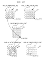
- space input idle link bit map 238 is a 4x5 bit array that represents the idle input links 94 between the input switches 92 and the center switches 96 in the space domain.
- Each row of space input idle link bit map 238 corresponds to one of the input stage switches 92.
- the entries in space input idle link bit map 238 for a given row (input stage) and column (center stage) indicate the idle state of the input link 94 between that input stage and center stage.
- An entry of 1 indicates that the input link is idle and available for assignment.
- a 0 value indicates that the input link is in use and is not available for assignment.
- a 0 entry in column X indicates that the extra center stage switch 234 is in use and the rearrangement method is in progress.
- Space output idle link bit map 240 is a 4x5 bit array that represents the idle output links between the output and the center switches 96 in the space domain. Each row of space output idle link bit map 240 corresponds to one of the output stage switches 100.
- the entries in the space output idle link bit map 240 for a given row (output switch) and column (center switch) indicate the idle state of the output link 98 between that output switch and center switch. An entry of 1 indicates that the output link is idle and available for assignment. A 0 value indicates that the output links is in use and is not available for assignment. A 0 entry in column X indicates that the extra center stage switch 224 is in use and the rearrangement method is in progress.
- the initialize idle link bit maps primitive (used only for start-up operations) creates both space input idle link bit map 238 and space output idle link bit map 240 for the preferred embodiment. All entries in the idle link bit maps are initialized to 1, indicating that all links are idle. Primitive: set_link(i/o, j, k)
- This primitive sets the k th bit of the j th row of the bit map specified by the "i/o" parameter to 1. If the bit map contains n elements and the value of j exceeds n, then the computer returns an error flag. Otherwise, the k th element is set to 1. Primitive: clear_link (i/o, j, k)
- the preferred method and system connect between an input switch stage i and an output switch stage k using the lowest numbered center stage switch available. This is accomplished by a process that hereinafter shall be called “pumping" space_n_link[i] and space_out_link[k]. That is, space_in_link[i] is logically "ANDed" with space_out_link[k] to determine c, the lowest numbered center stage switch with both an idle link to input stage i and an idle link to output stage k. The index of the first non-zero entry in the result of the logical AND is c, the lowest numbered center stage switch with both an idle link to input stage i and an idle link to output stage k. The two links to c are then marked as "busy" in space_in_link[i] and space_out_link[k] and the center stage number c is returned. Table 3 illustrates an embodiment of this primitive macro.
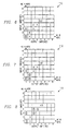
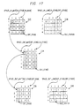
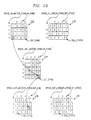
- FIGURE 16 illustrates the implementation data matrices after initialization.
- the corresponding entries in the connection path selection matrices space_in_mat 222, space_cnt_mat 234, and space_out_mat 236, for the example, are illustrated in FIGURE 16. Since there are no switch connections, all of the entries are 0.
- the contents of the space_in_link 238 and space_out_link 240 bit maps are as shown at initialization. Note that each input stage switch and each output stage switch has a 1 element for each idle center stage switch. In this example, after initialization, all five center stage switches are marked as "idle".
- FIGURE 17 shows the implementation data after the first connection.
- the first connection requested is to connect input line 1 to output line 1, or more simply, IL-1 ⁇ OL-1.
- the first step is to convert the input line number to an input switch stage number and an input number for that input switch stage. In this case, IL-1 ⁇ I(1,1).
- the output line number is converted to an output switch stage number and an output number for that output switch stage. In this case, OL-1 ⁇ O(1,1). So, we are going to make a connection between input stage 1 and output stage 1.
- the present method and system attempt to make the connection between input stage 1 and output stage 1 by using the lowest numbered center stage switch available, which in this case is center stage 1. This is accomplished by using the pump_list macro of TABLE 3 to compare space_in_link[1] with space_out_link[1] in FIGURE 16 and set the idle connects of the lowest center stage number common to both bit maps to "0". Then, the space_in_mat(i,j) and the space_out_mat(k,l) are set equal to that center stage number, and the space_cnt_mat(c,j) is set equal to k.
- the corresponding space matrix data entries are shown in FIGURE 17 and the resultant state of the space matrix 220 is shown in FIGURE 18.
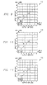
- the request to connect IL-13 to OL-7 converts to a request connect I(4,1) ⁇ O(2,3).
- the present method and system attempt to make the connection between input stage 4 and output stage 2 by using the lowest numbered center stage switch available, which in this case, is center stage switch number 4, as illustrated in FIGURE 20.
- the pump_list macro of Table 1 compares space_in_link[4] with space_out_link[2], determines the lowest center stage number common to both bit maps, and sets the idle status to "busy" in both bit maps. Then the space_in_mat(i,j) and the space_out_mat(k,l) are set equal to that center stage number and the space_cnt_mat(c,j) is set equal to k.
- FIGURE 21 The corresponding space matrix data entries are shown in FIGURE 21 and the resultant state of the space matrix is shown in FIGURE 22. This process is accomplished using the following statements from the connect routine as before:
- the put_back macro accomplishes the disconnect by breaking the connection between input stage 4 and output stage 2 and putting the freed-up center stage switch, number 4, back on the input/output stacks for subsequent use. More specifically, the put_back macro determines the freed-up center stage switch number and puts it back in the proper positions on both of the ordered-linked lists in space_in_link[4] and space_out_link[2]. Then, the space_in_mat(i,j), the space_cnt_mat(c,j), and the space_out_mat(k,l) are set equal to 0.
- the present method and system attempt to make the connection between input stage 4 and output stage 3 by using the lowest numbered center stage switch available.
- the X th or extra center stage switch 224 is the lowest number available center stage switch, as illustrated in FIGURE 25.
- the pump_list macro accomplishes this by comparing space_in_stack[4] with space_out_stack[3] in FIGURE 23, determining the lowest center stage number common to both bit maps (which in this case is center stage switch "X"), and setting the idle status to "busy” in both bit maps. Then, the space_n_mat(i,j) and the space_out_mat(k,l) are set equal to that center stage number and the space_cnt_mat(c,j) is set equal to k.
- An entry of 5 indicates that the X th center stage switch has been assigned and the rearrangement process is automatically invoked.
- the corresponding space matrix data entries during rearrangement are shown in FIGURE 24 and the resultant state of the space matrix during arrangement is shown in FIGURE 25.
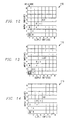
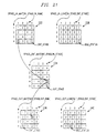
- connection I(4,3) ⁇ O(2,1) that FIGURE 26 shows is "rolled" from center stage switch number 2 onto center stage switch number 4. This roll is performed hitlessly by creating a head-end-bridge at input stage switch 4 and a receive-end-switch at output stage switch 2 as shown in FIGURE 27.
- the correct path is received at output stage switch 2 from center stage switch 4
- the original connection through center stage switch 2 is dropped as shown in FIGURE 28 and the space matrix data is updated as shown in FIGURE 29.
- This roll is performed hitlessly by creating a head-end-bridge at input stage switch 4 and an receive-end-switch at output stage switch 3 as shown in FIGURE 31.
- the correct path is received at outputs stage switch 3 from center stage switch 2, the original connection through center stage X 224 is dropped.
- FIGURE 32 shows the resulting state of the space matrix after rearrangement.
- FIGURE 33 shows the corresponding space matrix data entries after rearrangement.
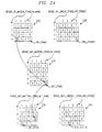
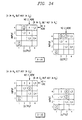
- FIGURE 34 the rearrangement aspects of the preferred embodiment are applied to the above example appear.
- the system of the preferred embodiment invokes the rearrangement process automatically.
- the system determines two center stage switches which will participate in the rearrangement process. This is accomplished using Paull's Method which is restated as follows:
- FIGURE 25 it is preferred to first transform the space_cnt_mat matrix data in FIGURE 24 into the format of FIGURE 4.
- FIGURE 34 illustrates the results of this transformation.
- the use of the dedicated center stage switch is indicated by the X in (r 4 ,c 3 ) of FIGURE 34.
- the next step is to find all symbol pairs (A,B) such that A is in row r 4 , but not in column c 3 , and B is in column c 3 , but not in row r 4 .
- A is set to 2.
- B is set to 4. Since there is only one value for A and one value for B, the (A,B) pair that requires the least changes is, obviously, the pair (2,4).
- the X ⁇ A sequence starts with the immediate connection through the extra element and ends up with the blocked cell being assigned to element A or 2, in this case.
- the blocked cell (r 3 ,c 4 )
- this step requires a circle around the 2 in row r 3 .
- the circled 2 is in (r 4 ,c 2 ).
- a search for a 4 in column c 2 is necessary. Since there is none, this sequence is complete. (Note that not all 2's get circled.)
- the X ⁇ B sequence starts with an immediate connection through the dedicated element 224 and ends up with the blocked cell being assigned to element B or 4, in this case.
- the blocked cell (r 3 ,c 4 )
- there is no 2 in c 4 so a circle goes around the 2 in c 4 .
- the circled 4 is in (r 3 ,c 3 ).
- a search for a 2 in r 3 takes place. Since there is none, the sequence generation process is complete. (Note that not all 4's get circled.)
- the flooding algorithm starts by finding the first element of the X ⁇ A sequence. If the X ⁇ A sequence is not ended, the first element of X ⁇ B sequence is found. Then, if the X ⁇ B sequence is not ended, the next element of the X ⁇ A sequence is found. This process continues until the shorter of the two sequences is completed. (So, the X ⁇ B sequence shown in FIGURE 34 is not really generated. It is shown here as an illustration of the alternate path.)
- a method and system are provided for finding an optimal path or connection configuration through a communications matrix in which an input stage array represents the assignment of input gates through an input switch to a center stage and has values that associate an input stage switch with an input gate and a center stage switch, a center stage array represents center stage switch connections between an output stage and input stage, and an output stage array represents output stage connections and has values that associate an output stage switch with an output gate and a center stage switch, and, further, wherein an idle input array represents idle input gates and an idle output array represents idle output gates, and in which the optimal connection path or configuration is determined by pumping the input stage array and the output stage array to determine an optimal center stage switch having idle connections between a predetermined input gate and a predetermined output gate.
- One important aspect of the present invention is its use in identifying the presence of a rearrangeably blocked condition of a rearrangeable communications matrix.
Landscapes
- Engineering & Computer Science (AREA)
- Computer Networks & Wireless Communication (AREA)
- Signal Processing (AREA)
- Physics & Mathematics (AREA)
- Mathematical Physics (AREA)
- Use Of Switch Circuits For Exchanges And Methods Of Control Of Multiplex Exchanges (AREA)
- Data Exchanges In Wide-Area Networks (AREA)
- Mobile Radio Communication Systems (AREA)
- Meter Arrangements (AREA)
- Peptides Or Proteins (AREA)
- Exchange Systems With Centralized Control (AREA)
- Multi Processors (AREA)
- Medicines That Contain Protein Lipid Enzymes And Other Medicines (AREA)
- Saccharide Compounds (AREA)
- Preparation Of Compounds By Using Micro-Organisms (AREA)
Abstract
Description
| | ACTION | |
| 1 | X→(r 1,c 1) | |
| 2 | B ○→B ○, X | |
| 3 | B ○, X→X | |
| 4 | A ○→A ○, B | |
| 5 | A ○,B→B | |
| 6 | X→X, A | |
| 7 | X, A→A |
| | ACTION | |
| 1 | X→(r 1,c 1) | |
| 2 | A ○→A ○, X | |
| 3 | A ○,X→X | |
| 4 | B ○→B ○, A | |
| 5 | B ○,A→A | |
| 6 | X→X, B | |
| 7 | X, B→B |
- N
- is the number of first (input) stage switches, which is equal to the number of third (output) stage switches;
- QuotN
- is the integer quotient of the argument divided by N; and
- RemN
- is the integer remainder after the argument has been divided by N.
| Data Definition: | space_in_mat(in_stage,in_num) |
| Statement: | space_in_mat(i,j) = c |
| Data Definition: | space_cnt_mat[cnt_stage,in_stage] |
| Statement: | space_cnt_mat(c,j) = k |
| Data Definition: | space_out_mat[out_stage,out_num] |
| Statement: | space_out_mat(k,l) = c |
| Data Definition: | space_in_link[in_stage,cnt_stage] |
| Data Definition: | space_out_link[out_stage,cnt_stage] |
| Primitive: | init_links() |
| Primitive: | set_link(i/o, j, k) |
| Primitive: | clear_link (i/o, j, k) |
| Primitive: | pump_link(space_in_link[i],space_out_link [k]) |


Claims (6)
- A method of finding a path through a communications matrix, comprising the steps of:representing the assignment of a center stage switch (96) through an input stage switch (92) to input gates (90) using an input stage array (222);representing center stage switch connections (94, 98) between an input stage switch (92) and an output stage switch (100) by a center stage array (234);representing the assignment of a center stage switch (96) through an output stage switch (100) to output gates (102) by an output stage array (236);representing idle input switch links to said center stage switch (96) by an idle input link array (238) and idle output switch links from said center stage switch (96) by an idle output link array (240); andassociating said input stage array (222), said output stage array (236), and said center stage array (234) according to the values of said idle input link array (238) and said idle output link array (240) to determine an optimal center stage switch having an idle input link between a predetermined input gate and said optimal center stage switch and an idle output link between said optimal center stage and a predetermined output gate.
- The method of claim 1, wherein the step of associating said input stage array (222), said output stage array (236), and said center stage array (234) according to the values of said idle input link array (238) and said idle output link array (240) comprises pumping said input stage array (222), said output stage array (236), and said center stage array (234).
- The method of claim 2, further comprising the step of tracking said idle input switch links and said idle output switch links using said idle input link array (238) and said idle output link array (240).
- A system for finding a path through a communication matrix, comprisingan input stage array (222) for representing the assignment of a center stage switch (96) through an input stage switch (92) to input gates (90);an center stage switch (234) for representing center stage switch connections (94, 98) between an input stage switch (92) and an output stage switch (100);an output stage array (236) for representing the assignment of a center stage switch (96) through an output stage switch (100) to output gates (102);an idle input link array (238) for representing idle input switch links to said center stage switch (96) and an idle output link array (240) for representing idle output switch links from said center stage switch (96); andmeans for associating said input stage array (222), said output stage array (236), and said center stage array (234) using information from said idle input link array (238) and said idle output link array (240) to determine an optimal center stage switch having an idle input link between a predetermined input gate and said optimal center stage switch and an idle output link between said optimal center stage and a predetermined output gate.
- The system of claim 4, wherein said means for associating said input stage array (222), said output stage array (236), and said center stage array (234) according to the values of said idle input link array (238) and said idle output link array (240) comprises pumping means for pumping said input stage array (222), said output stage array (236), and said center stage array (234).
- The system of claim 4, further comprising means for tracking said idle input switch links using said idle input link array (238) and said idle output switch links using said idle output link array (240).
Applications Claiming Priority (2)
| Application Number | Priority Date | Filing Date | Title |
|---|---|---|---|
| US88359492A | 1992-05-14 | 1992-05-14 | |
| US883594 | 1992-05-14 |
Publications (3)
| Publication Number | Publication Date |
|---|---|
| EP0569913A2 EP0569913A2 (en) | 1993-11-18 |
| EP0569913A3 EP0569913A3 (en) | 1994-08-24 |
| EP0569913B1 true EP0569913B1 (en) | 1999-12-29 |
Family
ID=25382918
Family Applications (1)
| Application Number | Title | Priority Date | Filing Date |
|---|---|---|---|
| EP93107586A Expired - Lifetime EP0569913B1 (en) | 1992-05-14 | 1993-05-10 | Connection path selection method for cross-connect communications networks |
Country Status (11)
| Country | Link |
|---|---|
| US (1) | US5408231A (en) |
| EP (1) | EP0569913B1 (en) |
| JP (1) | JPH0638256A (en) |
| KR (1) | KR930024351A (en) |
| CN (1) | CN1081053A (en) |
| AT (1) | ATE188321T1 (en) |
| CA (1) | CA2096208C (en) |
| DE (1) | DE69327423T2 (en) |
| FI (1) | FI932177A (en) |
| SG (1) | SG50629A1 (en) |
| TW (1) | TW223205B (en) |
Families Citing this family (69)
| Publication number | Priority date | Publication date | Assignee | Title |
|---|---|---|---|---|
| US5317310A (en) * | 1992-05-14 | 1994-05-31 | Alcatel Network Systems, Inc. | Method and system for selecting an optimal rearrangement sequence for a cross-connect communication matrix |
| SG49119A1 (en) * | 1992-05-14 | 1998-05-18 | Alcatel Nv | Methods and system for immediately connecting and reswitching digital cross-connect networks |
| JP3094849B2 (en) * | 1995-06-21 | 2000-10-03 | 株式会社日立製作所 | Parallel computer and its multistage network |
| US5805574A (en) * | 1995-07-28 | 1998-09-08 | Motorola, Inc. | Adaptive switch resource allocation in a satellite communication system |
| NZ315055A (en) * | 1995-08-07 | 1998-10-28 | British Telecomm | Route finding in communications networks |
| US5754120A (en) * | 1995-12-21 | 1998-05-19 | Lucent Technologies | Network congestion measurement method and apparatus |
| US5987027A (en) * | 1996-11-08 | 1999-11-16 | Alcatel | Cross-connect multirate/multicast SDH/SONET rearrangement procedure and cross-connect using same |
| DE19742656C2 (en) * | 1997-09-26 | 2003-02-27 | Ericsson Telefon Ab L M | Method and device for controlling a switching device |
| SE515666C2 (en) * | 1998-07-17 | 2001-09-17 | Ericsson Telefon Ab L M | Reliable and robust ATM gearbox |
| US6195553B1 (en) | 1999-04-20 | 2001-02-27 | Analytical Graphics, Inc. | Method and apparatus for determining optimal paths among objects of a communications network |
| KR100332410B1 (en) * | 1999-09-28 | 2002-04-13 | 서평원 | Method for searching multiple path of virtual container signals in similar CLOS network |
| GB2365660A (en) * | 2000-03-10 | 2002-02-20 | British Telecomm | Circuit switching |
| US20030058848A1 (en) * | 2000-04-11 | 2003-03-27 | Velio Communications, Inc. | Scheduling clos networks |
| US7260092B2 (en) | 2000-04-11 | 2007-08-21 | Lsi Corporation | Time slot interchanger |
| US7301941B2 (en) * | 2000-04-11 | 2007-11-27 | Lsi Corporation | Multistage digital cross connect with synchronized configuration switching |
| US6870838B2 (en) | 2000-04-11 | 2005-03-22 | Lsi Logic Corporation | Multistage digital cross connect with integral frame timing |
| IL136176A (en) | 2000-05-16 | 2004-02-19 | Lightscape Networks Ltd | Rearrangement of data streams |
| US7111073B1 (en) | 2000-05-30 | 2006-09-19 | Cisco Technology, Inc. | Apparatus for estimating delay and jitter between network routers |
| US6868068B1 (en) | 2000-06-30 | 2005-03-15 | Cisco Technology, Inc. | Method and apparatus for estimating delay and jitter between network routers |
| US6816487B1 (en) * | 2000-07-20 | 2004-11-09 | Nortel Networks Limited | Mapping of high bandwidth connections in a multi-stage switch |
| US6912203B1 (en) | 2000-07-31 | 2005-06-28 | Cisco Technology, Inc. | Method and apparatus for estimating delay and jitter between many network routers using measurements between a preferred set of routers |
| US6614904B1 (en) * | 2000-08-09 | 2003-09-02 | Alcatel | Apparatus and method for effecting a communication arrangement between switch arrays |
| US6687253B1 (en) * | 2000-10-19 | 2004-02-03 | Interactic Holdings, Llc | Scaleable wormhole-routing concentrator |
| US6996058B2 (en) * | 2001-04-27 | 2006-02-07 | The Boeing Company | Method and system for interswitch load balancing in a communications network |
| US7346049B2 (en) | 2002-05-17 | 2008-03-18 | Brian Patrick Towles | Scheduling connections in a multi-stage switch to retain non-blocking properties of constituent switching elements |
| CN1323496C (en) * | 2002-05-23 | 2007-06-27 | 中兴通讯股份有限公司 | Method of circuit business automatic distribution in synchronous digital system optical transmission system |
| US7802049B2 (en) * | 2002-10-30 | 2010-09-21 | Intel Corporation | Links having flexible lane allocation |
| US7330428B2 (en) | 2002-12-11 | 2008-02-12 | Lsi Logic Corporation | Grooming switch hardware scheduler |
| US7958295B1 (en) * | 2005-03-31 | 2011-06-07 | Pmc-Sierra Us, Inc. | Method and apparatus for finding subset maxima and minima in SAS expanders and related devices |
| US8150019B2 (en) * | 2007-08-10 | 2012-04-03 | Smith Robert B | Path redundant hardware efficient communications interconnect system |
| TWI350486B (en) | 2007-11-26 | 2011-10-11 | Ind Tech Res Inst | Biometrics method and apparatus and biometric data encryption method thereof |
| US7860100B2 (en) * | 2008-10-01 | 2010-12-28 | Cisco Technology, Inc. | Service path selection in a service network |
| US8442043B2 (en) * | 2008-12-29 | 2013-05-14 | Cisco Technology, Inc. | Service selection mechanism in service insertion architecture data plane |
| US8780896B2 (en) | 2010-12-29 | 2014-07-15 | Juniper Networks, Inc. | Methods and apparatus for validation of equal cost multi path (ECMP) paths in a switch fabric system |
| US8798077B2 (en) | 2010-12-29 | 2014-08-05 | Juniper Networks, Inc. | Methods and apparatus for standard protocol validation mechanisms deployed over a switch fabric system |
| US8743885B2 (en) | 2011-05-03 | 2014-06-03 | Cisco Technology, Inc. | Mobile service routing in a network environment |
| US20130227190A1 (en) * | 2012-02-27 | 2013-08-29 | Raytheon Company | High Data-Rate Processing System |
| US9794379B2 (en) | 2013-04-26 | 2017-10-17 | Cisco Technology, Inc. | High-efficiency service chaining with agentless service nodes |
| DE102013019643A1 (en) * | 2013-11-22 | 2015-05-28 | Siemens Aktiengesellschaft | Two-stage crossbar distributor and method of operation |
| US9479443B2 (en) | 2014-05-16 | 2016-10-25 | Cisco Technology, Inc. | System and method for transporting information to services in a network environment |
| US9379931B2 (en) | 2014-05-16 | 2016-06-28 | Cisco Technology, Inc. | System and method for transporting information to services in a network environment |
| US10417025B2 (en) | 2014-11-18 | 2019-09-17 | Cisco Technology, Inc. | System and method to chain distributed applications in a network environment |
| US9660909B2 (en) | 2014-12-11 | 2017-05-23 | Cisco Technology, Inc. | Network service header metadata for load balancing |
| USRE48131E1 (en) | 2014-12-11 | 2020-07-28 | Cisco Technology, Inc. | Metadata augmentation in a service function chain |
| US9762402B2 (en) | 2015-05-20 | 2017-09-12 | Cisco Technology, Inc. | System and method to facilitate the assignment of service functions for service chains in a network environment |
| US11044203B2 (en) | 2016-01-19 | 2021-06-22 | Cisco Technology, Inc. | System and method for hosting mobile packet core and value-added services using a software defined network and service chains |
| US10187306B2 (en) | 2016-03-24 | 2019-01-22 | Cisco Technology, Inc. | System and method for improved service chaining |
| US10931793B2 (en) | 2016-04-26 | 2021-02-23 | Cisco Technology, Inc. | System and method for automated rendering of service chaining |
| US10419550B2 (en) | 2016-07-06 | 2019-09-17 | Cisco Technology, Inc. | Automatic service function validation in a virtual network environment |
| US10320664B2 (en) | 2016-07-21 | 2019-06-11 | Cisco Technology, Inc. | Cloud overlay for operations administration and management |
| US10218616B2 (en) | 2016-07-21 | 2019-02-26 | Cisco Technology, Inc. | Link selection for communication with a service function cluster |
| US10225270B2 (en) | 2016-08-02 | 2019-03-05 | Cisco Technology, Inc. | Steering of cloned traffic in a service function chain |
| US10218593B2 (en) | 2016-08-23 | 2019-02-26 | Cisco Technology, Inc. | Identifying sources of packet drops in a service function chain environment |
| US10361969B2 (en) | 2016-08-30 | 2019-07-23 | Cisco Technology, Inc. | System and method for managing chained services in a network environment |
| US10225187B2 (en) | 2017-03-22 | 2019-03-05 | Cisco Technology, Inc. | System and method for providing a bit indexed service chain |
| US10178646B2 (en) | 2017-04-12 | 2019-01-08 | Cisco Technology, Inc. | System and method to facilitate slice management in a network environment |
| US10884807B2 (en) | 2017-04-12 | 2021-01-05 | Cisco Technology, Inc. | Serverless computing and task scheduling |
| US10257033B2 (en) | 2017-04-12 | 2019-04-09 | Cisco Technology, Inc. | Virtualized network functions and service chaining in serverless computing infrastructure |
| US10333855B2 (en) | 2017-04-19 | 2019-06-25 | Cisco Technology, Inc. | Latency reduction in service function paths |
| US10554689B2 (en) | 2017-04-28 | 2020-02-04 | Cisco Technology, Inc. | Secure communication session resumption in a service function chain |
| US10735275B2 (en) | 2017-06-16 | 2020-08-04 | Cisco Technology, Inc. | Releasing and retaining resources for use in a NFV environment |
| US10798187B2 (en) | 2017-06-19 | 2020-10-06 | Cisco Technology, Inc. | Secure service chaining |
| US10397271B2 (en) | 2017-07-11 | 2019-08-27 | Cisco Technology, Inc. | Distributed denial of service mitigation for web conferencing |
| US10673698B2 (en) | 2017-07-21 | 2020-06-02 | Cisco Technology, Inc. | Service function chain optimization using live testing |
| US11063856B2 (en) | 2017-08-24 | 2021-07-13 | Cisco Technology, Inc. | Virtual network function monitoring in a network function virtualization deployment |
| US10791065B2 (en) | 2017-09-19 | 2020-09-29 | Cisco Technology, Inc. | Systems and methods for providing container attributes as part of OAM techniques |
| US11018981B2 (en) | 2017-10-13 | 2021-05-25 | Cisco Technology, Inc. | System and method for replication container performance and policy validation using real time network traffic |
| US10541893B2 (en) | 2017-10-25 | 2020-01-21 | Cisco Technology, Inc. | System and method for obtaining micro-service telemetry data |
| US10666612B2 (en) | 2018-06-06 | 2020-05-26 | Cisco Technology, Inc. | Service chains for inter-cloud traffic |
Family Cites Families (7)
| Publication number | Priority date | Publication date | Assignee | Title |
|---|---|---|---|---|
| NL284712A (en) * | 1961-11-24 | |||
| DE1252754B (en) * | 1965-07-24 | 1967-10-26 | Standard Elektrik Lorenz Aktien gesellschaft, Stuttgart Zuflenhausen | Path search network for determining a free path through a switching network, for telecommunication systems, in particular telephone exchanges |
| SE381548B (en) * | 1974-12-20 | 1975-12-08 | Ellemtel Utvecklings Ab | DEVICE FOR CONTROLLING THE SELECTION IRON |
| US4038497A (en) * | 1975-05-12 | 1977-07-26 | Collins Arthur A | Hardwired marker for time folded tst switch with distributed control logic and automatic path finding, set up and release |
| US4394541A (en) * | 1981-01-02 | 1983-07-19 | Seiden Lewis J | Three stage minimum configuration conditionally non-blocking matrix |
| US4991168A (en) * | 1989-05-08 | 1991-02-05 | At&T Bell Laboratories | Concurrent multi-stage network control arrangement |
| US4993016A (en) * | 1989-05-08 | 1991-02-12 | At&T Bell Laboratories | Network control arrangement for processing a plurality of connection requests |
-
1993
- 1993-05-10 EP EP93107586A patent/EP0569913B1/en not_active Expired - Lifetime
- 1993-05-10 AT AT93107586T patent/ATE188321T1/en not_active IP Right Cessation
- 1993-05-10 SG SG1996007198A patent/SG50629A1/en unknown
- 1993-05-10 DE DE69327423T patent/DE69327423T2/en not_active Expired - Fee Related
- 1993-05-13 CA CA002096208A patent/CA2096208C/en not_active Expired - Fee Related
- 1993-05-13 JP JP5135246A patent/JPH0638256A/en not_active Ceased
- 1993-05-13 FI FI932177A patent/FI932177A/en unknown
- 1993-05-14 KR KR1019930008401A patent/KR930024351A/en active IP Right Grant
- 1993-05-14 CN CN93105746A patent/CN1081053A/en active Pending
- 1993-06-23 TW TW082105045A patent/TW223205B/zh active
-
1994
- 1994-07-29 US US08/282,705 patent/US5408231A/en not_active Expired - Fee Related
Also Published As
| Publication number | Publication date |
|---|---|
| TW223205B (en) | 1994-05-01 |
| EP0569913A3 (en) | 1994-08-24 |
| DE69327423D1 (en) | 2000-02-03 |
| KR930024351A (en) | 1993-12-22 |
| ATE188321T1 (en) | 2000-01-15 |
| US5408231A (en) | 1995-04-18 |
| CN1081053A (en) | 1994-01-19 |
| SG50629A1 (en) | 1998-07-20 |
| EP0569913A2 (en) | 1993-11-18 |
| CA2096208C (en) | 2001-07-17 |
| FI932177A (en) | 1993-11-15 |
| FI932177A0 (en) | 1993-05-13 |
| JPH0638256A (en) | 1994-02-10 |
| DE69327423T2 (en) | 2000-06-08 |
| CA2096208A1 (en) | 1993-11-15 |
Similar Documents
| Publication | Publication Date | Title |
|---|---|---|
| EP0569913B1 (en) | Connection path selection method for cross-connect communications networks | |
| US5535197A (en) | Shared buffer switching module | |
| US4022982A (en) | Apparatus for rearrangement of a switching network | |
| EP0398543B1 (en) | Concurrent multi-stage network control method | |
| US5343194A (en) | Methods and system for immediately connecting and reswitching digital cross-connect networks | |
| JPH10294729A (en) | Cross connection multi-rate/multi-cast sdh/sonet rearrangement procedure and cross connection using it | |
| EP0397370B1 (en) | Network control arrangement for processing a plurality of connection requests | |
| US5369400A (en) | Method and system for hitlessly rearranging connections in a cross-connect communications network | |
| JPS62155648A (en) | Packet switch device and method for distributing copies of data packet to a plurality of addresses | |
| EP0590864A2 (en) | Free space optical, growable packet switching arrangement | |
| EP0590865A2 (en) | Multistage growable optical packet switching arrangement with bypass | |
| US5216668A (en) | Modulated nonblocking parallel banyan network | |
| EP0397371A1 (en) | Network control arrangement based on topological equivalence | |
| US4845704A (en) | Switching system for integrated voice/data communications | |
| US5132965A (en) | Nonblocking parallel banyan network | |
| EP0569906B1 (en) | Methods and system for immediately connecting and reswitching digital cross-connect networks | |
| EP1113627B1 (en) | Method of determining network paths in a three stage switching matrix | |
| EP0569905B1 (en) | Method and system for selecting an optimal rearrangement sequence for a cross-connect communication matrix | |
| KR960027840A (en) | Terabit class packet exchange apparatus and method | |
| JP2578946B2 (en) | Optical ATM switching system | |
| US5455956A (en) | Connection tree rearrangement method and system for rearrangebly-blocked DSM networks | |
| CN101309222A (en) | Method, apparatus and system for regulating network routing | |
| Zulfin et al. | The Implementation of Routing Division Algorithm on The 16 x16 Benes Switching Network | |
| US20080143473A1 (en) | Digital Cross-Connect Path Selection Method | |
| US6888825B1 (en) | Cross-connect with shared storage |
Legal Events
| Date | Code | Title | Description |
|---|---|---|---|
| PUAI | Public reference made under article 153(3) epc to a published international application that has entered the european phase |
Free format text: ORIGINAL CODE: 0009012 |
|
| AK | Designated contracting states |
Kind code of ref document: A2 Designated state(s): AT BE CH DE ES FR GB IT LI NL SE |
|
| PUAL | Search report despatched |
Free format text: ORIGINAL CODE: 0009013 |
|
| AK | Designated contracting states |
Kind code of ref document: A3 Designated state(s): AT BE CH DE ES FR GB IT LI NL SE |
|
| 17P | Request for examination filed |
Effective date: 19941019 |
|
| 17Q | First examination report despatched |
Effective date: 19970630 |
|
| GRAG | Despatch of communication of intention to grant |
Free format text: ORIGINAL CODE: EPIDOS AGRA |
|
| GRAG | Despatch of communication of intention to grant |
Free format text: ORIGINAL CODE: EPIDOS AGRA |
|
| GRAH | Despatch of communication of intention to grant a patent |
Free format text: ORIGINAL CODE: EPIDOS IGRA |
|
| GRAH | Despatch of communication of intention to grant a patent |
Free format text: ORIGINAL CODE: EPIDOS IGRA |
|
| RAP1 | Party data changed (applicant data changed or rights of an application transferred) |
Owner name: ALCATEL |
|
| GRAA | (expected) grant |
Free format text: ORIGINAL CODE: 0009210 |
|
| AK | Designated contracting states |
Kind code of ref document: B1 Designated state(s): AT BE CH DE ES FR GB IT LI NL SE |
|
| PG25 | Lapsed in a contracting state [announced via postgrant information from national office to epo] |
Ref country code: SE Free format text: THE PATENT HAS BEEN ANNULLED BY A DECISION OF A NATIONAL AUTHORITY Effective date: 19991229 Ref country code: NL Free format text: LAPSE BECAUSE OF FAILURE TO SUBMIT A TRANSLATION OF THE DESCRIPTION OR TO PAY THE FEE WITHIN THE PRESCRIBED TIME-LIMIT Effective date: 19991229 Ref country code: LI Free format text: LAPSE BECAUSE OF FAILURE TO SUBMIT A TRANSLATION OF THE DESCRIPTION OR TO PAY THE FEE WITHIN THE PRESCRIBED TIME-LIMIT Effective date: 19991229 Ref country code: ES Free format text: THE PATENT HAS BEEN ANNULLED BY A DECISION OF A NATIONAL AUTHORITY Effective date: 19991229 Ref country code: CH Free format text: LAPSE BECAUSE OF FAILURE TO SUBMIT A TRANSLATION OF THE DESCRIPTION OR TO PAY THE FEE WITHIN THE PRESCRIBED TIME-LIMIT Effective date: 19991229 Ref country code: BE Free format text: LAPSE BECAUSE OF FAILURE TO SUBMIT A TRANSLATION OF THE DESCRIPTION OR TO PAY THE FEE WITHIN THE PRESCRIBED TIME-LIMIT Effective date: 19991229 Ref country code: AT Free format text: LAPSE BECAUSE OF FAILURE TO SUBMIT A TRANSLATION OF THE DESCRIPTION OR TO PAY THE FEE WITHIN THE PRESCRIBED TIME-LIMIT Effective date: 19991229 |
|
| REF | Corresponds to: |
Ref document number: 188321 Country of ref document: AT Date of ref document: 20000115 Kind code of ref document: T |
|
| REG | Reference to a national code |
Ref country code: CH Ref legal event code: EP |
|
| REF | Corresponds to: |
Ref document number: 69327423 Country of ref document: DE Date of ref document: 20000203 |
|
| ITF | It: translation for a ep patent filed |
Owner name: JACOBACCI & PERANI S.P.A. |
|
| ET | Fr: translation filed | ||
| NLV1 | Nl: lapsed or annulled due to failure to fulfill the requirements of art. 29p and 29m of the patents act | ||
| REG | Reference to a national code |
Ref country code: CH Ref legal event code: PL |
|
| PLBE | No opposition filed within time limit |
Free format text: ORIGINAL CODE: 0009261 |
|
| STAA | Information on the status of an ep patent application or granted ep patent |
Free format text: STATUS: NO OPPOSITION FILED WITHIN TIME LIMIT |
|
| 26N | No opposition filed | ||
| REG | Reference to a national code |
Ref country code: GB Ref legal event code: IF02 |
|
| PGFP | Annual fee paid to national office [announced via postgrant information from national office to epo] |
Ref country code: FR Payment date: 20030512 Year of fee payment: 11 |
|
| PGFP | Annual fee paid to national office [announced via postgrant information from national office to epo] |
Ref country code: DE Payment date: 20030514 Year of fee payment: 11 |
|
| PGFP | Annual fee paid to national office [announced via postgrant information from national office to epo] |
Ref country code: GB Payment date: 20040504 Year of fee payment: 12 |
|
| PG25 | Lapsed in a contracting state [announced via postgrant information from national office to epo] |
Ref country code: DE Free format text: LAPSE BECAUSE OF NON-PAYMENT OF DUE FEES Effective date: 20041201 |
|
| PG25 | Lapsed in a contracting state [announced via postgrant information from national office to epo] |
Ref country code: FR Free format text: LAPSE BECAUSE OF NON-PAYMENT OF DUE FEES Effective date: 20050131 |
|
| REG | Reference to a national code |
Ref country code: FR Ref legal event code: ST |
|
| PG25 | Lapsed in a contracting state [announced via postgrant information from national office to epo] |
Ref country code: IT Free format text: LAPSE BECAUSE OF NON-PAYMENT OF DUE FEES Effective date: 20050510 Ref country code: GB Free format text: LAPSE BECAUSE OF NON-PAYMENT OF DUE FEES Effective date: 20050510 |
|
| GBPC | Gb: european patent ceased through non-payment of renewal fee |
Effective date: 20050510 |