EP0565483B1 - Basin in a waste water plant - Google Patents
Basin in a waste water plant Download PDFInfo
- Publication number
- EP0565483B1 EP0565483B1 EP93810171A EP93810171A EP0565483B1 EP 0565483 B1 EP0565483 B1 EP 0565483B1 EP 93810171 A EP93810171 A EP 93810171A EP 93810171 A EP93810171 A EP 93810171A EP 0565483 B1 EP0565483 B1 EP 0565483B1
- Authority
- EP
- European Patent Office
- Prior art keywords
- tank
- channel
- wall
- water
- basin
- Prior art date
- Legal status (The legal status is an assumption and is not a legal conclusion. Google has not performed a legal analysis and makes no representation as to the accuracy of the status listed.)
- Expired - Lifetime
Links
Images
Classifications
-
- E—FIXED CONSTRUCTIONS
- E03—WATER SUPPLY; SEWERAGE
- E03F—SEWERS; CESSPOOLS
- E03F5/00—Sewerage structures
- E03F5/12—Emergency outlets
Definitions
- the invention relates to a basin in a sewage plant according to the preamble of claim 1.
- Retention basins, flood relief, rain basins etc., in wastewater plants serve to temporarily store the amount of wastewater that exceeds the capacity of the sewage treatment plant in the event of a major rain event and to later discharge it to the sewage treatment plant. If the storage capacity of the pool is no longer sufficient, the amount of water flowing in must be fed directly to flowing or standing water.
- an overflow channel can be arranged on the side of the retention basin, the overflow edge of which faces the basin essentially at the level of the maximum possible water level in the basin.
- a baffle in front of the overflow channel.
- baffle wall is floating and to use it on swivel arms which are articulated on the overflow channel side.
- the object of the present invention is to form a channel lying between the basin and the overflow channel, in which means are provided which prevent the entry of floating impurities both at the beginning and during a rain event.
- the wall By arranging a wall in a channel upstream of the overflow channel, the wall can be firmly connected to the building or can be designed as part of the building. If the wall is pulled up to the ceiling of the basin or is suspended from it, the space above the overflow channel and the associated drainage channel and the basin space for smells and also access for people can be separated.
- the wall can also be designed such that it can be raised and lowered in order to retain any solid bodies that have been washed in when the channel is filled, on the pool side of the lowered wall.
- a line connecting the channel to the basin which is formed on the pool side by a flap that can be closed with rising water level in the pool, serves to empty the channel when the water flow into the pool decreases and to return sedimented substances to the pool.
- an overflow channel 7 is arranged on the right basin wall 5. This can be attached to the wall 5 or be part of the wall 5. On the pool side, the overflow edge 9 of the overflow channel 7 is at the height h 1 .
- the overflow channel 7 is connected to a drain line 11, which leads to the receiving water or into open water.
- a drain line 11 In the left basin wall 13 there is an inlet opening 15 through which water is supplied to the basin 1.
- a collecting trough 17 can be let in, which is connected at the front by a line 19 to a sewage treatment plant.
- a channel 21 is arranged on the basin side of the overflow edge 9, the overflow edge 23 of which lies at the height h 2 .
- the overflow edge 23 of the channel 21 is somewhat lower than that of the overflow channel 7.
- the channel 21 can be connected to the sewage plant at the end by a closable connecting line 25 for emptying.
- a wall 27 extending over the entire length of the channel 21 is arranged between the two overflow edges 9 and 23. The lower edge 29 of the wall 27 is below the height h 2 , ie it dips into the cross section of the channel 21 when it is filled with water.
- the design of the basin 1 according to FIG. 2 differs from that in FIG. 1 in that the wall 27 on the ceiling 31 of the basin 1 is attached or abuts against it. Furthermore, instead of the connecting line 25, which leaves the end of the channel 21, a bushing 33 leads from the channel 21 into the basin 1.
- the feedthrough 33 can be closed by a flap 35, which lies in front of the feedthrough 33 with increasing water level and thus prevents the passage of water from the channel 21 into the basin 1.
- the wall 27 is arranged to be vertically displaceable or pivotable, so that it can sink to the bottom of the channel 21 when it is empty and thus prevents solid bodies 37 floating from the basin 1 under the bottom edge 29 of the basin 1 when the channel 21 is filled Wall can get into the overflow channel 7.
- the wall 27 can be articulated to pairs of levers 39 and be designed to float, or it can be displaceably guided by a vertical guide (not shown) attached to the side walls of the pool.
- a line 41 is provided for the passage 33 through the channel 21, which projects beyond the channel 21 downwards and can be closed by a valve 43, which only allows water to enter the channel 21 when the valve 43 is below the water level h 3 lies and thereby no impurities can get into the channel 21 through the line 41.
- the valve 43 can of course also be used for emptying the channel 21, especially when there is a risk of frost in winter.
- Floating solids 37 which are introduced into the basin 1 with the water, are retained by the wall 27 and cannot flow below the lower edge 29, over the overflow edge 9 into the overflow channel 7 and from there into a receiving water or into a body of water. So that the wall 27 in the channel 21 is always functional, the channel 21 is preferably always filled with water, or it is filled up immediately when a major rain event occurs.
- the channel 21 is filled with service water up to the overflow edge height h 2 .
- the water in the basin 1 flows through the line 19 to the sewage plant in a predefinable amount per unit time.
- Sediments and the floating solids 37 collect in the trough 17 and can be fed from there to the wastewater treatment plant.
- the sediments that remain in the channel 21 can also be fed to the sewage system by opening the connecting line 25.
- the wall 27 extends to the ceiling 31, it can be achieved that the space of the basin 1 and the space above the overflow channel 7 are separated from one another for odors.
- the vapors of volatile substances that have been introduced into the basin 1 cannot get out of the building through the overflow channel 7 and the drain line 4.
- the wall 27 forms together with the channel 21 an olfactory siphon.
- the wall 27 also serves as access security for the operating personnel.
- the channel 21 is emptied automatically after the water level has dropped, because as soon as the water level within the channel 21 is above that in the pool 1, the static water pressure ensures that the flap 35 is opened and the water in the channel 21 is returned to the pool 1 and can flow from there through line 19 into the sewage treatment plant.
- the aim is that the channel 21 is always filled, on the one hand to serve as an odor siphon and to prevent solid bodies from being washed under the wall 27 at the beginning of the rain event.
- the water must be drained from channel 21 in winter to prevent frost damage.
- valve 43 allows water to enter the channel 21 at the moment when the water level h 3 has reached the valve 43 and therefore none on the valve
- Water floating solid 37 can be flushed through the line 41 into the channel 21. It is also not possible to pass solid bodies under the wall 27 if the latter can be moved vertically as shown in FIG. 3 and only rises when the level within the channel 21 has reached a certain height, which is sufficient around the wall 27, which is designed to be floatable is to give a boost. As a result, floating solid bodies 37 are retained on the pool side.
Landscapes
- Business, Economics & Management (AREA)
- Emergency Management (AREA)
- Health & Medical Sciences (AREA)
- Life Sciences & Earth Sciences (AREA)
- Engineering & Computer Science (AREA)
- Hydrology & Water Resources (AREA)
- Public Health (AREA)
- Water Supply & Treatment (AREA)
- Sewage (AREA)
- Sink And Installation For Waste Water (AREA)
- Removal Of Floating Material (AREA)
Abstract
Description
Gegenstand der Erfindung ist ein Becken in einer Abwasseranlage gemäss Oberbegriff des Anspruches 1.The invention relates to a basin in a sewage plant according to the preamble of
Rückhaltebecken, Hochwasserentlastungen, Regenbecken etc., in Abwasseranlagen, im folgenden kurz Becken genannt, dienen dazu, bei einem grösseren Regenereignis die anfallende Abwassermenge, welche die Kapazität der Kläranlage übersteigt, vorübergehend zu speichern und später dosiert an die Kläranlage abzuleiten. Genügt auch die Speicherkapazität des Beckens nicht mehr, so muss die darüber hinaus zufliessende Wassermenge direkt einem fliessenden oder stehenden Gewässer zugeleitet werden. Zu diesem Zweck kann seitlich des Rückhaltebeckens eine Überlaufrinne angeordnet sein, deren dem Becken zugewandte Überlaufkante im wesentlichen auf der Höhe des maximal möglichen Wasserspiegels im Becken liegt. Um zu verhindern, dass auf dem Wasser aufschwimmende Festkörper vom Becken über die Überlaufkante in die Ueberlaufrinne und von dort in ein Gewässer gelangen können, ist es bekannt, zulaufseitig vor der Überlaufrinne eine Tauchwand anzuordnen. Die Unterkante einer solchen Tauchwand liegt etwas unterhalb der Höhe der Überfallkante der Überlaufrinne. Dadurch können die vom Becken her zur Überlaufrinne getragenen Festkörper beckenseitig der Tauchwand zurückgehalten werden. Es ist allerdings nicht möglich die bei aufsteigendem Wasserspiegel bereits zwischen der Tauchwand und der Überfallkante befindlichen schwimmenden Festkörper zurückzuhalten. Es ist daher auch schon vorgeschlagen worden, die Tauchwand schwimmend auszubilden und an Schwenkarmen, welche überlaufrinnenseitig angelenkt sind, einzusetzen. Bei tiefem Wasserspiegel senkt sich die schwimmende Tauchwand mit dem Wasserspiegel nach unten und legt sich an der Wand des Beckens unterhalb der Ueberlaufrinne an.Retention basins, flood relief, rain basins etc., in wastewater plants, hereinafter referred to as basins, serve to temporarily store the amount of wastewater that exceeds the capacity of the sewage treatment plant in the event of a major rain event and to later discharge it to the sewage treatment plant. If the storage capacity of the pool is no longer sufficient, the amount of water flowing in must be fed directly to flowing or standing water. For this purpose, an overflow channel can be arranged on the side of the retention basin, the overflow edge of which faces the basin essentially at the level of the maximum possible water level in the basin. In order to prevent solids floating on the water from reaching the basin over the overflow edge into the overflow channel and from there into a body of water, it is known to arrange a baffle in front of the overflow channel. The lower edge of such a baffle is slightly below the height of the overflow edge of the overflow channel. As a result, the solids carried from the pool to the overflow channel can be retained on the pool side of the baffle. However, it is not possible to hold back the floating solids that are already between the baffle and the overflow edge when the water level rises. It has therefore already been proposed to design the baffle wall to be floating and to use it on swivel arms which are articulated on the overflow channel side. When the water level is low, the floating wall drops down with the water level and lies on the wall of the pool below the overflow channel.
Beim Aufstauen im Überlaufbecken können bei dieser bekannten Tauchwand keine Festkörper zwischen die Tauchwand und die Beckenwand gelangen und auch nicht von dort in die Überlaufrinne, weil die Tauchwand erst zu steigen beginnt, wenn sich der Wasserspiegel mit den aufschwimmenden Festkörpern über der Unterkante der Tauchwand befindet.When damming up in the overflow basin, no solid bodies can get between the baffle wall and the pool wall and not from there into the overflow channel, because the baffle wall only begins to rise when the water level with the floating solid bodies is above the lower edge of the baffle wall.
Aus der FR-A-2637822 ist ein Becken mit den Merkmalen des Oberbegriffs des Anspruchs 1 bekannt. Bei diesem Becken ist zwischen der Überlaufrinne und dem Einstaubecken ein zusätzlicher Raum ausgebildet, der durch eine an seinem tiefsten Punkt liegende Verbindungsbohrung und einer auf der Verbindungsbohrung angeordneten Klappe mit dem Becken verbunden ist. Bei dieser Anordnung ist es notwendig, mit einer schwenkbaren Tauchwand oder mit einem Sieb den Eintritt von aufschwimmenden Verunreinigungen in den Raum zwischen dem Becken und der Überlaufrinne zu verhindern. Das Anbringen einer zusätzlichen Tauchwand oder eines Siebes oder Gitters ist kostspielig und benötigt Unterhalt.From FR-A-2637822 a pool with the features of the preamble of
Die Aufgabe der vorliegenden Erfindung ist die Ausbildung eines zwischen dem Becken und der Überlaufrinne liegenden Kanales, bei dem Mittel vorgesehen sind, die den Zutritt von aufschwimmenden Verunreinigungen sowohl zu Beginn aus auch während eines Regenereignisses verhindern.The object of the present invention is to form a channel lying between the basin and the overflow channel, in which means are provided which prevent the entry of floating impurities both at the beginning and during a rain event.
Gelöst wird diese Aufgabe durch die kennzeichnenden Merkmale des Anspruches 1.This object is achieved by the characterizing features of
Durch die Anordnung einer Wand in einem der Ueberlaufrinne beckenseitig vorgelagerten Kanal, kann die Wand fest mit dem Bauwerk verbunden bzw. als Teil des Bauwerkes ausgestaltet sein. Wird die Wand bis an die Decke des Beckens hochgezogen oder ist an diesem aufgehängt, so kann der Raum über der Ueberlaufrinne und dem dazugehörigen Ablaufkanal und der Raum des Beckens für Gerüche und auch den Zutritt für Personen getrennt werden. Die Wand kann auch heb- und senkbar ausgebildet sein, um beim Füllen des Kanales allenfalls eingeschwemmte Festkörper beckenseitig der abgesenkten Wand zurückzuhalten.By arranging a wall in a channel upstream of the overflow channel, the wall can be firmly connected to the building or can be designed as part of the building. If the wall is pulled up to the ceiling of the basin or is suspended from it, the space above the overflow channel and the associated drainage channel and the basin space for smells and also access for people can be separated. The wall can also be designed such that it can be raised and lowered in order to retain any solid bodies that have been washed in when the channel is filled, on the pool side of the lowered wall.
Eine den Kanal mit dem Becken verbindende Leitung, die beckenseitig durch eine mit steigendem Wasserspiegel im Becken verschliessbare Klappe ausgebildet ist, dient dazu, beim Rückgang des Wasserzuflusses in das Becken den Kanal zu entleeren und darin sedimentierte Stoffe in das Bekken zurückzuführen. Mit der erfindungsgemässen Anordnung der Wand kann, falls sie an der Decke anschliesst, auch verhindert werden, dass flüchtige Stoffe wie Benzin und dergleichen, die in das Becken gelangen, dieses verlassen und einem Gewässer zugeleitet werden.A line connecting the channel to the basin, which is formed on the pool side by a flap that can be closed with rising water level in the pool, serves to empty the channel when the water flow into the pool decreases and to return sedimented substances to the pool. With the arrangement of the wall according to the invention, if it is connected to the ceiling, it is also possible to prevent volatile substances such as gasoline and the like from entering the basin leave and be directed to a body of water.
Anhand dreier Figuren wird die Erfindung näher erläutert. Es zeigen:
Figur 1- einen Querschnitt durch ein Becken,
- Figur 2
- einen Querschnitt durch ein weiteres Becken mit einer als Geruchsschleuse ausgebildeten Wand und
Figur 3- einen Querschnitt durch eine heb- und senkbare Wand
- Figure 1
- a cross section through a basin,
- Figure 2
- a cross section through another basin with a wall designed as an odor trap and
- Figure 3
- a cross section through a wall that can be raised and lowered
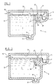
In einem Rückhaltebecken oder Entlastungsbauwerk, kurz Becken 1 genannt, einer Abwasseranlage 3 ist an der rechten Beckenwand 5 eine Überlaufrinne 7 angeordnet. Diese kann an der Wand 5 befestigt oder Teil der Wand 5 sein. Beckenseitig liegt die Überlaufkante 9 der Überlaufrinne 7 auf der Höhe h1. Die Ueberlaufrinne 7 ist mit einer Ablaufleitung 11 verbunden, die zum Vorfluter oder in offenes Gewässer führt. In der linken Beckenwand 13 ist eine Zuflussöffnung 15 eingelassen, durch welche dem Becken 1 Wasser zugeleitet wird. Im Boden des Bekkens 1 kann eine Sammelrinne 17 eingelassen sein, die stirnseitig durch eine Leitung 19 mit einer Kläranlage verbunden ist.In a retention basin or relief structure, briefly called
Beckenseitig von der Überlaufkante 9 ist ein Kanal 21 angeordnet, dessen Überfallkante 23 auf der Höhe h2 liegt. Vorzugsweise liegt die Ueberfallkante 23 des Kanals 21 etwas tiefer als diejenige der Ueberlaufrinne 7. Der Kanal 21 kann stirnseitig für dessen Entleerung durch eine verschliessbare Verbindungsleitung 25 mit der Kläranlage verbunden sein. Zwischen den beiden Überlaufkanten 9 und 23 ist eine sich über die gesamte Länge des Kanals 21 erstreckenden Wand 27 angeordnet. Die Unterkante 29 der Wand 27 liegt unterhalb der Höhe h2, d.h. sie taucht in den Querschnitt des Kanals 21 ein, wenn dieser mit Wasser gefüllt ist.A
Die Ausgestaltung des Beckens 1 nach Figur 2 unterscheidet sich von derjenigen in Figur 1 dadurch, dass die Wand 27 an der Decke 31 des Beckens 1 befestigt ist oder an dieser anliegt. Im weiteren tritt anstelle der Verbindungsleitung 25, welche stirnseitig den Kanal 21 verlässt, eine Durchführung 33, die vom Kanal 21 in das Becken 1 führt. Die Durchführung 33 ist durch eine Klappe 35 verschliessbar, welche sich mit steigendem Wasserspiegel vor die Durchführung 33 legt und damit den Durchtritt von Wasser aus dem Kanal 21 in das Becken 1 verhindert.The design of the
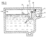
In einer weiteren Ausgestaltung des Beckens 1 ist die Wand 27 vertikal verschieb- oder schwenkbar angeordnet, damit sie bei entleertem Kanal 21 auf dessen Boden absinken kann und damit verhindert, dass beim Auffüllen des Kanals 21 schwimmende Festkörper 37 vom Becken 1 unter der Unterkante 29 der Wand hindurch in die Ueberlaufrinne 7 gelangen können. Die Wand 27 kann, wie in Figur 3 dargestellt, an Hebelpaaren 39 angelenkt und schwimmend ausgebildet sein oder einer an den Seitenwänden des Beckens angebrachten vertikalen Führung (keine Abbildung) verschieblich geführt sein.In a further embodiment of the
Nach der Erfindung ist zur Durchführung 33 durch den Kanal 21 eine Leitung 41 vorgesehen, die den Kanal 21 nach unten überragt und durch ein Ventil 43 verschliessbar ist, welches den Zutritt von Wasser zum Kanal 21 erst erlaubt, wenn das Ventil 43 unterhalb dem Wasserspiegel h3 liegt und dadurch keine Verunreinigungen durch die Leitung 41 in den Kanal 21 hineingelangen können. Das Ventil 43 kann selbstverständlich auch zur Entleerung des Kanales 21 vor allem bei Frostgefahr im Winter benutzt werden.According to the invention, a
Der Einsatz der Leitung 41 mit dem Ventil 43 kann selbstverständlich auch in den Kanälen gemäss den Ausgestaltungen des Beckens in den Figuren 1 und 2 eingesetzt werden.The use of the
Im folgenden wird die Funktionsweise der erfindungsgemässen eintauchenden Wandanordnung erläutert. Bei einem Regenereignis wird durch die Zuflussöffnung 15 Wasser in das Becken 1 eingeleitet und kann durch die Sammelrinne 17 und die Leitung 19 einer Abwasseranlage zugeführt werden. Übersteigt die zugeleitete Wassermenge die Aufnahmekapazität der Abwasserreinigungsanlage, d.h. wenn mehr Wasser durch die Zuflussöffnung 15 in das Becken 1 einfliesst als durch die Abflussleitung 19 abfliessen kann, so steigt der Wasserspiegel im Becken 1 sukzessive an. Wird die Höhe h2 erreicht, so fliesst Wasser in den Kanal 21 und füllt diesen sehr rasch auf. Schwimmende Festkörper 37, die mit dem Wasser in das Becken 1 eingeleitet werden, werden von der Wand 27 zurückgehalten und können nicht unter deren Unterkante 29 hindurch über die Ueberlaufkante 9 in die Überlaufrinne 7 und von dort in einen Vorfluter oder in ein Gewässer abfliessen. Damit die Wand 27 im Kanal 21 stets funktionsfähig ist, ist der Kanal 21 vorzugsweise immer mit Wasser gefüllt, oder er wird sofort bei Eintritt eines grösseren Regenereignisses aufgefüllt.The mode of operation of the immersing wall arrangement according to the invention is explained below. In the event of a rain event, water is introduced into the
Damit verhindert werden kann, dass auch zu Beginn des Aufstauens keine Festkörper 37 über die Überfallkante 23 in den Kanal 21 und unter der Wand 27 hindurch gelangen können, wird der Kanal 21 mit Brauchwasser bis zur Überfallkantenhöhe h2 aufgefüllt.In order to prevent that no
Nach dem Regenereignis und Rückgang des Zuflusses durch die Zuflussöffnung 15 fliesst das im Becken 1 befindliche Wasser durch die Leitung 19 in vorgebbarer Menge pro Zeiteinheit der Kläranlage zu. Sedimente und die aufschwimmenden Festkörper 37 sammeln sich in der Rinne 17 und können von dort Abwasserreinigungsanlage zugeführt werden. Die Sedimente, welche im Kanal 21 zurückbleiben, können durch Öffnen der Verbindungsleitung 25 ebenfalls der Abwasseranlage zugeleitet werden.After the rain event and decrease in the inflow through the inflow opening 15, the water in the
In der Ausgestaltung nach Figur 2, bei der die Wand 27 bis zur Decke 31 geführt ist, kann erreicht werden, dass der Raum des Beckens 1 sowie der Raum über der Überlaufrinne 7 für Gerüche voneinander getrennt sind. So können die Dämpfe von flüchtigen Stoffen, die in das Becken 1 eingeführt worden sind, nicht durch die Überlaufrinne 7 und die Ablaufleitung 4 aus dem Bauwerk hinausgelangen. Die Wand 27 bildet zusammen mit dem Kanal 21 einen Geruchssiphon. Gleichzeitig dient die Wand 27 auch als Zutrittssicherung für das Bedienungspersonal.In the embodiment according to FIG. 2, in which the
Die Entleerung des Kanals 21 nach dem Absinken des Wasserspiegels erfolgt automatisch, denn sobald der Wasserspiegel innerhalb des Kanals 21 über demjenigen im Becken 1 liegt, sorgt der statische Wasserdruck dafür, dass die Klappe 35 geöffnet wird und das im Kanal 21 befindliche Wasser zurück ins Becken 1 und von dort durch Leitung 19 in die Kläranlage fliessen kann.The
Ueberlicherweise wird jedoch angestrebt, dass der Kanal 21 stets gefüllt ist, um zum einen als Geruchssiphon zu dienen und um zu verhindern, dass zu Beginn des Regenereignisses, Festkörper unter der Wand 27 hindurchgeschwemmt werden können. Selbstverständlich muss im Winter das Wasser aus dem Kanal 21 abgelassen werden um keine Frostschäden entstehen zu lassen.Usually, however, the aim is that the
Es ist selbstverständlich nicht nötig, dauernd Wasser im Kanal 21 zu haben, da durch entsprechende Steuerungsmittel das Ventil 43 den Zutritt von Wasser in den Kanal 21 in dem Moment ermöglicht, wenn der Wasserspiegel h3 oberhalb dem Ventil 43 angelangt ist und daher keine auf dem Wasser aufschwimmenden Festkörper 37 durch die Leitung 41 in den Kanal 21 hineingespült werden können. Es können auch keine Festkörper unter der Wand 27 hindurchgeleitet werden, wenn diese wie in Figur 3 dargestellt vertikal beweglich ist und sich erst anhebt, wenn das Niveau innerhalb des Kanales 21 eine gewisse Höhe erreicht hat, die genügt um der Wand 27, die schwimmbar ausgeführt ist, Auftrieb zu geben. Dadurch bleiben auf jeden Fall schwimmende Festkörper 37 beckenseitig zurückgehalten.It is of course not necessary to have water permanently in the
Claims (6)
- Tank (1) in a sewage system (3), having an overflow channel (7), which is disposed along the tank (1) and is provided with an overflow edge (9) for the discharging of the quantity of water which exceeds the holding capacity of the sewage-treatment plant, and having a wall (27), which holds-back solid bodies (37) floating on the surface of the water in the tank (1), and which extends into the water surface, said wall protruding from above into a duct (21), which is disposed between the overflow channel (7) and the tank (1), characterised in that the duct (21) has a pipe (41) extending to the tank (1), which pipe is closable at the tank end by means of a valve (43), and through which pipe (41) water can be introduced into the duct (21) from the tank (1).
- Tank according to claim 1, characterised in that the overflow edge (23) at the duct (21) lies at a lower level (h2) than the overflow edge (9) of the overflow channel (7).
- Tank according to claim 2, characterised in that the valve (43) is only closed by accumulated water in the tank (1) when the water level (h3) lies above the mouth of the aperture of the passage (33) or respectively of the pipe (41).
- Tank according to one of claims 1 to 3, characterised in that the wall (27) abuts against the cover (31) of the tank (1).
- Tank according to one of claims 1 to 3, characterised in that the wall (27) is vertically displaceably connected to the tank (1).
- Tank according to claim 5, characterised in that the wall (27) is raisable and lowerable by means of one or more pairs of levers (39) or vertical guides.
Applications Claiming Priority (2)
| Application Number | Priority Date | Filing Date | Title |
|---|---|---|---|
| CH1157/92 | 1992-04-09 | ||
| CH1157/92A CH685570A5 (en) | 1992-04-09 | 1992-04-09 | Pool. |
Publications (2)
| Publication Number | Publication Date |
|---|---|
| EP0565483A1 EP0565483A1 (en) | 1993-10-13 |
| EP0565483B1 true EP0565483B1 (en) | 1997-05-21 |
Family
ID=4203816
Family Applications (1)
| Application Number | Title | Priority Date | Filing Date |
|---|---|---|---|
| EP93810171A Expired - Lifetime EP0565483B1 (en) | 1992-04-09 | 1993-03-05 | Basin in a waste water plant |
Country Status (4)
| Country | Link |
|---|---|
| EP (1) | EP0565483B1 (en) |
| AT (1) | ATE153410T1 (en) |
| CH (1) | CH685570A5 (en) |
| DE (1) | DE59306488D1 (en) |
Families Citing this family (3)
| Publication number | Priority date | Publication date | Assignee | Title |
|---|---|---|---|---|
| GB9925384D0 (en) * | 1999-10-27 | 1999-12-29 | Bryant Group Plc | Apparatus for stromwater retention and release and method of use thereof |
| DE20103875U1 (en) * | 2001-03-07 | 2001-08-16 | Vollmar Gmbh | Sewage system with cleaning device |
| KR100429686B1 (en) * | 2001-04-09 | 2004-05-03 | (주) 상원이엔씨 | A storm overflow diverging tank |
Family Cites Families (3)
| Publication number | Priority date | Publication date | Assignee | Title |
|---|---|---|---|---|
| CH634371A5 (en) * | 1979-02-23 | 1983-01-31 | Nill Walter Schlosserei | Apparatus with downflow baffle for stormwater tanks or clarification tanks |
| CH678281A5 (en) * | 1988-10-14 | 1991-08-30 | Werner Nill | |
| CH679413A5 (en) * | 1989-12-01 | 1992-02-14 | Werner Nill |
-
1992
- 1992-04-09 CH CH1157/92A patent/CH685570A5/en not_active IP Right Cessation
-
1993
- 1993-03-05 AT AT93810171T patent/ATE153410T1/en not_active IP Right Cessation
- 1993-03-05 EP EP93810171A patent/EP0565483B1/en not_active Expired - Lifetime
- 1993-03-05 DE DE59306488T patent/DE59306488D1/en not_active Expired - Fee Related
Also Published As
| Publication number | Publication date |
|---|---|
| DE59306488D1 (en) | 1997-06-26 |
| EP0565483A1 (en) | 1993-10-13 |
| ATE153410T1 (en) | 1997-06-15 |
| CH685570A5 (en) | 1995-08-15 |
Similar Documents
| Publication | Publication Date | Title |
|---|---|---|
| DE2920978C2 (en) | Device for anaerobic wastewater treatment | |
| DE3915076C2 (en) | ||
| DE3305409A1 (en) | Storm separation works | |
| AT400599B (en) | SCREEN ARRANGEMENT FOR OVERFLOW POOLS | |
| EP0722524B1 (en) | Tank system | |
| DE3510171A1 (en) | Liquid-retention device for installation into a liquid-storage chamber | |
| DE60303497T2 (en) | Rainwater harvesting | |
| EP0565483B1 (en) | Basin in a waste water plant | |
| EP0535375B1 (en) | Installation for carrying wrongly directed thrash from a rainwater-channel into a sewer-channel | |
| EP0690179A1 (en) | Floating downflow baffle | |
| EP1548193B1 (en) | Device for preventing water entering a manhole shaft | |
| DE19632911C2 (en) | Liquid separator with separation device | |
| DE19509466A1 (en) | Liq. storage tank with closable inlet and outlet | |
| DE102009025388A1 (en) | Device for protecting container of separating device i.e. volatile liquid separator, against penetration of liquid over outlet of container, has valve opening located along flow direction of liquid over outlet behind outlet opening | |
| AT406260B (en) | CLEANING OR Settling tanks | |
| EP1039052B1 (en) | Method for cleaning a collecting tank for fluids, a collecting tank and a flushing drum | |
| CH658088A5 (en) | WASTEWATER DRAIN, CONSISING OF A DRAINAGE TANK WITH AT LEAST ONE INLET AND DRAIN PIPE AND USE THEREOF. | |
| EP0518912B1 (en) | Clearing or sedimentation tank | |
| DE2907998A1 (en) | Sewage plant rain water separator - has surface water removal outlet in collector chamber on separating side | |
| DE8508382U1 (en) | Liquid retention device for installation in a liquid storage space | |
| DE202018100026U1 (en) | Round clarifier or settling tank | |
| EP1138363A2 (en) | Device and method for withdrawing purified water from a container in the biological purification of waste water | |
| EP1101000B1 (en) | Device for rinsing drains | |
| DE19830192B4 (en) | Hydraulic structure and method for water discharge of a sewage plant | |
| DE19919571C2 (en) | Sewer washer |
Legal Events
| Date | Code | Title | Description |
|---|---|---|---|
| PUAI | Public reference made under article 153(3) epc to a published international application that has entered the european phase |
Free format text: ORIGINAL CODE: 0009012 |
|
| AK | Designated contracting states |
Kind code of ref document: A1 Designated state(s): AT CH DE FR GB IT LI |
|
| 17P | Request for examination filed |
Effective date: 19940406 |
|
| 17Q | First examination report despatched |
Effective date: 19950807 |
|
| GRAG | Despatch of communication of intention to grant |
Free format text: ORIGINAL CODE: EPIDOS AGRA |
|
| GRAH | Despatch of communication of intention to grant a patent |
Free format text: ORIGINAL CODE: EPIDOS IGRA |
|
| GRAH | Despatch of communication of intention to grant a patent |
Free format text: ORIGINAL CODE: EPIDOS IGRA |
|
| GRAA | (expected) grant |
Free format text: ORIGINAL CODE: 0009210 |
|
| AK | Designated contracting states |
Kind code of ref document: B1 Designated state(s): AT CH DE FR GB IT LI |
|
| PG25 | Lapsed in a contracting state [announced via postgrant information from national office to epo] |
Ref country code: IT Free format text: LAPSE BECAUSE OF FAILURE TO SUBMIT A TRANSLATION OF THE DESCRIPTION OR TO PAY THE FEE WITHIN THE PRE;WARNING: LAPSES OF ITALIAN PATENTS WITH EFFECTIVE DATE BEFORE 2007 MAY HAVE OCCURRED AT ANY TIME BEFORE 2007. THE CORRECT EFFECTIVE DATE MAY BE DIFFERENT FROM THE ONE RECORDED.SCRIBED TIME-LIMIT Effective date: 19970521 Ref country code: GB Effective date: 19970521 Ref country code: FR Effective date: 19970521 |
|
| REF | Corresponds to: |
Ref document number: 153410 Country of ref document: AT Date of ref document: 19970615 Kind code of ref document: T |
|
| REG | Reference to a national code |
Ref country code: CH Ref legal event code: EP |
|
| REF | Corresponds to: |
Ref document number: 59306488 Country of ref document: DE Date of ref document: 19970626 |
|
| REG | Reference to a national code |
Ref country code: CH Ref legal event code: NV Representative=s name: HANS RUDOLF GACHNANG PATENTANWALT |
|
| EN | Fr: translation not filed | ||
| GBV | Gb: ep patent (uk) treated as always having been void in accordance with gb section 77(7)/1977 [no translation filed] |
Effective date: 19970521 |
|
| PG25 | Lapsed in a contracting state [announced via postgrant information from national office to epo] |
Ref country code: AT Free format text: LAPSE BECAUSE OF NON-PAYMENT OF DUE FEES Effective date: 19980305 |
|
| PLBE | No opposition filed within time limit |
Free format text: ORIGINAL CODE: 0009261 |
|
| STAA | Information on the status of an ep patent application or granted ep patent |
Free format text: STATUS: NO OPPOSITION FILED WITHIN TIME LIMIT |
|
| 26N | No opposition filed | ||
| PG25 | Lapsed in a contracting state [announced via postgrant information from national office to epo] |
Ref country code: DE Free format text: LAPSE BECAUSE OF NON-PAYMENT OF DUE FEES Effective date: 19981201 |
|
| PGFP | Annual fee paid to national office [announced via postgrant information from national office to epo] |
Ref country code: CH Payment date: 20120319 Year of fee payment: 20 |
|
| REG | Reference to a national code |
Ref country code: CH Ref legal event code: PL |