EP0564157A1 - Apparatus for analyzing particles - Google Patents
Apparatus for analyzing particles Download PDFInfo
- Publication number
- EP0564157A1 EP0564157A1 EP93302265A EP93302265A EP0564157A1 EP 0564157 A1 EP0564157 A1 EP 0564157A1 EP 93302265 A EP93302265 A EP 93302265A EP 93302265 A EP93302265 A EP 93302265A EP 0564157 A1 EP0564157 A1 EP 0564157A1
- Authority
- EP
- European Patent Office
- Prior art keywords
- light
- fluorescence
- sample liquid
- particle
- liquid flow
- Prior art date
- Legal status (The legal status is an assumption and is not a legal conclusion. Google has not performed a legal analysis and makes no representation as to the accuracy of the status listed.)
- Withdrawn
Links
- 239000002245 particle Substances 0.000 title claims abstract description 87
- 239000007788 liquid Substances 0.000 claims abstract description 30
- 230000005284 excitation Effects 0.000 claims abstract description 29
- 230000003595 spectral effect Effects 0.000 claims abstract description 23
- 238000002189 fluorescence spectrum Methods 0.000 claims abstract description 12
- 230000003287 optical effect Effects 0.000 claims description 14
- 238000012545 processing Methods 0.000 claims description 5
- 238000001228 spectrum Methods 0.000 abstract description 7
- 239000008280 blood Substances 0.000 abstract description 2
- 210000004369 blood Anatomy 0.000 abstract description 2
- 210000002700 urine Anatomy 0.000 abstract description 2
- 238000010586 diagram Methods 0.000 description 22
- 238000001514 detection method Methods 0.000 description 5
- MHMNJMPURVTYEJ-UHFFFAOYSA-N fluorescein-5-isothiocyanate Chemical compound O1C(=O)C2=CC(N=C=S)=CC=C2C21C1=CC=C(O)C=C1OC1=CC(O)=CC=C21 MHMNJMPURVTYEJ-UHFFFAOYSA-N 0.000 description 5
- 238000003384 imaging method Methods 0.000 description 5
- 108010004729 Phycoerythrin Proteins 0.000 description 3
- 230000000694 effects Effects 0.000 description 3
- 238000005286 illumination Methods 0.000 description 3
- 238000009825 accumulation Methods 0.000 description 2
- 239000007850 fluorescent dye Substances 0.000 description 2
- 238000000034 method Methods 0.000 description 2
- 239000013307 optical fiber Substances 0.000 description 2
- 238000006243 chemical reaction Methods 0.000 description 1
- 239000003085 diluting agent Substances 0.000 description 1
- 239000011521 glass Substances 0.000 description 1
- 230000001678 irradiating effect Effects 0.000 description 1
- 150000002540 isothiocyanates Chemical class 0.000 description 1
- 238000005259 measurement Methods 0.000 description 1
- 238000013208 measuring procedure Methods 0.000 description 1
- 238000012986 modification Methods 0.000 description 1
- 230000004048 modification Effects 0.000 description 1
- 239000004033 plastic Substances 0.000 description 1
- 229920003023 plastic Polymers 0.000 description 1
- XJMOSONTPMZWPB-UHFFFAOYSA-M propidium iodide Chemical compound [I-].[I-].C12=CC(N)=CC=C2C2=CC=C(N)C=C2[N+](CCC[N+](C)(CC)CC)=C1C1=CC=CC=C1 XJMOSONTPMZWPB-UHFFFAOYSA-M 0.000 description 1
- 238000002310 reflectometry Methods 0.000 description 1
- 229920006395 saturated elastomer Polymers 0.000 description 1
- 239000004065 semiconductor Substances 0.000 description 1
- 239000000725 suspension Substances 0.000 description 1
- 239000012780 transparent material Substances 0.000 description 1
- 238000011144 upstream manufacturing Methods 0.000 description 1
Images


Classifications
-
- G01N15/1433—
-
- G—PHYSICS
- G01—MEASURING; TESTING
- G01N—INVESTIGATING OR ANALYSING MATERIALS BY DETERMINING THEIR CHEMICAL OR PHYSICAL PROPERTIES
- G01N15/00—Investigating characteristics of particles; Investigating permeability, pore-volume, or surface-area of porous materials
- G01N15/10—Investigating individual particles
- G01N15/14—Electro-optical investigation, e.g. flow cytometers
- G01N15/1434—Electro-optical investigation, e.g. flow cytometers using an analyser being characterised by its optical arrangement
-
- G—PHYSICS
- G01—MEASURING; TESTING
- G01N—INVESTIGATING OR ANALYSING MATERIALS BY DETERMINING THEIR CHEMICAL OR PHYSICAL PROPERTIES
- G01N15/00—Investigating characteristics of particles; Investigating permeability, pore-volume, or surface-area of porous materials
- G01N15/10—Investigating individual particles
- G01N15/14—Electro-optical investigation, e.g. flow cytometers
- G01N15/1456—Electro-optical investigation, e.g. flow cytometers without spatial resolution of the texture or inner structure of the particle, e.g. processing of pulse signals
- G01N15/1459—Electro-optical investigation, e.g. flow cytometers without spatial resolution of the texture or inner structure of the particle, e.g. processing of pulse signals the analysis being performed on a sample stream
-
- G—PHYSICS
- G01—MEASURING; TESTING
- G01J—MEASUREMENT OF INTENSITY, VELOCITY, SPECTRAL CONTENT, POLARISATION, PHASE OR PULSE CHARACTERISTICS OF INFRARED, VISIBLE OR ULTRAVIOLET LIGHT; COLORIMETRY; RADIATION PYROMETRY
- G01J3/00—Spectrometry; Spectrophotometry; Monochromators; Measuring colours
- G01J3/28—Investigating the spectrum
- G01J3/44—Raman spectrometry; Scattering spectrometry ; Fluorescence spectrometry
- G01J3/4406—Fluorescence spectrometry
-
- G—PHYSICS
- G01—MEASURING; TESTING
- G01N—INVESTIGATING OR ANALYSING MATERIALS BY DETERMINING THEIR CHEMICAL OR PHYSICAL PROPERTIES
- G01N15/00—Investigating characteristics of particles; Investigating permeability, pore-volume, or surface-area of porous materials
- G01N15/10—Investigating individual particles
- G01N15/14—Electro-optical investigation, e.g. flow cytometers
- G01N15/1404—Fluid conditioning in flow cytometers, e.g. flow cells; Supply; Control of flow
-
- G—PHYSICS
- G01—MEASURING; TESTING
- G01N—INVESTIGATING OR ANALYSING MATERIALS BY DETERMINING THEIR CHEMICAL OR PHYSICAL PROPERTIES
- G01N15/00—Investigating characteristics of particles; Investigating permeability, pore-volume, or surface-area of porous materials
- G01N15/10—Investigating individual particles
- G01N15/14—Electro-optical investigation, e.g. flow cytometers
- G01N2015/1477—Multiparameters
-
- G—PHYSICS
- G01—MEASURING; TESTING
- G01N—INVESTIGATING OR ANALYSING MATERIALS BY DETERMINING THEIR CHEMICAL OR PHYSICAL PROPERTIES
- G01N21/00—Investigating or analysing materials by the use of optical means, i.e. using sub-millimetre waves, infrared, visible or ultraviolet light
- G01N21/62—Systems in which the material investigated is excited whereby it emits light or causes a change in wavelength of the incident light
- G01N21/63—Systems in which the material investigated is excited whereby it emits light or causes a change in wavelength of the incident light optically excited
- G01N21/64—Fluorescence; Phosphorescence
- G01N2021/6417—Spectrofluorimetric devices
-
- G—PHYSICS
- G01—MEASURING; TESTING
- G01N—INVESTIGATING OR ANALYSING MATERIALS BY DETERMINING THEIR CHEMICAL OR PHYSICAL PROPERTIES
- G01N21/00—Investigating or analysing materials by the use of optical means, i.e. using sub-millimetre waves, infrared, visible or ultraviolet light
- G01N21/62—Systems in which the material investigated is excited whereby it emits light or causes a change in wavelength of the incident light
- G01N21/63—Systems in which the material investigated is excited whereby it emits light or causes a change in wavelength of the incident light optically excited
- G01N21/64—Fluorescence; Phosphorescence
- G01N21/6428—Measuring fluorescence of fluorescent products of reactions or of fluorochrome labelled reactive substances, e.g. measuring quenching effects, using measuring "optrodes"
- G01N2021/6439—Measuring fluorescence of fluorescent products of reactions or of fluorochrome labelled reactive substances, e.g. measuring quenching effects, using measuring "optrodes" with indicators, stains, dyes, tags, labels, marks
Definitions
- the present invention relates to apparatus for analyzing a sample liquid containing particles such as blood and urine, by irradiating the sample liquid with light, detecting signals from the particles, and analyzing the particles.
- the apparatus obtains spectra of light signals by using spectral means such as a prism or diffraction grating, so as to obtain more specific particle information.
- a fluorescent excitation (excited) light is irradiated at a sample liquid containing particles such as dyed cells, and the fluorescence emitted from the particles is detected, and the particles are classified and counted.
- An example of such apparatus is a flow cytometer. Also known is an imaging flow cytometer for picking up the particle images.
- wavelength selection means such as an optical filter and a dichroic mirror is needed.
- a corresponding plurality of optical detectors are needed.
- Japanese Laid-open Patent Hei. 2-24535 discloses a flow cytometer capable of calculating the fluorescence intensity distribution (intensity against wavelength) of the particles, by separating the fluorescence from the specimen into consecutive wavelength components by spectroscopic means, and detecting the separated wavelength components by using a one-dimensional photoelectric detector.
- the optical filter With the optical filter, however, it is difficult to separate beams of light of similar wavelengths, although it is possible to separate beams of light of very different wavelengths.
- the wavelength distribution of the light cannot be measured. That is, it is not possible to know the quantity of fluorescence of a particular wavelength that is emitted from a particular position of a cell. This may be possible by taking the cell image by using a video camera and analyzing the image, but each cell must be imaged and the image processed. Thus, the apparatus becomes complicated.
- apparatus for analyzing particles comprising: a first light source for illuminating with fluorescence excitation light a sample liquid flow containing particles; spectral means for separating fluorescence emitted in a specific direction from a particle to produce a fluorescence spectrum; amplifying means for amplifying the fluorescence spectrum produced by the spectral means; an image sensor for detecting different wavelengths of the amplified fluorescence spectrum; and signal processing means for receiving a signal from the image sensor and resetting the signal of the image sensor for each particle.
- the sample liquid is formed into a sheath flow in which the suspension of particles is covered with a laminar sheath liquid in order to align the particles in a row near the middle of the liquid flow.
- a sheath liquid is a diluent liquid or the like.
- the fluorescence emitted from the particle as a result of irradiation with the fluorescence excitation light is separated by the spectral means, and a fluorescence spectrum is obtained.
- This fluorescence spectrum is amplified by the amplifying means, such as an image intensifier, and the intensity of a range of wavelengths may be measured by the image sensor.
- the fluorescence spectra of a plurality of particles can be measured simultaneously.
- the fluorescence excitation light passing through the particle and the scattered light scattered by the particle are detected by a light detecting means, passage of the particle through a detection region may be judged by the signal processing means.
- the signal of the image sensor is reset, before the signal is read out (if the particle is not of interest) or after the signal is read out (if the particle is of interest).
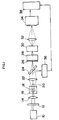
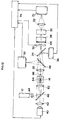
- Fig. 1 is a schematic diagram of an apparatus for analyzing particles in Embodiment 1.
- a light source 10 is a fluorescence excitation (excited) light source, which is a laser light source such as Ar,He-Cd or semiconductor laser, or a light source of continuous emission type such as Xe lamp.
- a fluorescence excitation (excited) light source which is a laser light source such as Ar,He-Cd or semiconductor laser, or a light source of continuous emission type such as Xe lamp.
- a desired excitation (excited) wavelength can be selected by using a wavelength selection filter 12.
- the filter 12 is unnecessary.
- a condensing lens 14 is a lens for focusing the light from the fluorescence excitation light source 10 into a sample liquid flow 18 flowing in the center of a flow cell 16, and the spot size when concentrated is desired to be about 10 x 200 ⁇ m.
- the flow cell 16 is made of transparent material of glass or plastics, and comprises a lead-in passage narrowed gradually, a narrow measuring passage connected to the lead-in passage, a sheath liquid feeding port provided in the lead-in passage, and a discharge port provided downstream of the measuring passage.
- Numeral 20 is a shield plate for shielding the direct light from the light source 10.
- the scattered light is reflected by a dichroic mirror 24, and enters light detecting means, such as a CCD line sensor 36.
- the signal from the line sensor 36 is fed into the signal processor 38, and passing of the particle is detected. At the same time, the size and number of passing particles are detected.
- the shield plate When sensing the particle by the transmitted light, the shield plate must be removed.
- Fig. 2 shows the characteristic diagram of the dichroic mirror 24.
- the spectroscopic means 28 is for converting the fluorescence emitted from the cell into a spectrum.
- a fluorescence spectral image as shown in Fig. 3 is obtained on the incident plane of amplifying means, such as image intensifier 30.
- Numeral 58 denotes a particle.
- the image intensifier 30 is a photoelectron multiplier, and is used for amplifying the fluorescence spectral image separated by the spectroscopic means 28.
- the fluorescence spectral image entering the incident plane (photoelectric plane) of the image intensifier 30 is amplified, and sent out to an output plane (fluorescence plane) of the image intensifier 30.
- the fluorescence spectral image sent out of the image intensifier 30 is focused on a light receiving element (image sensor) 34 by a relay lens 32 or an optical fiber.
- the fluorescence intensity of each wavelength is measured.
- a CCD line sensor or a photo diode array as the light receiving element (image sensor) 34.
- the fluorescence intensity can be measured at a resolution of 1 nm per pixel.
- a CCD line sensor When a CCD line sensor is used as a light receiving element (image sensor) 34, since it is of charge accumulation type, i.e. different to a photo diode array, the accumulated charge must be reset by some way or other (otherwise the fluorescence intensity of all passing particles is counted (added) up). Accordingly, by making use of the signal from the line sensor 36 as the light detector, the accumulated charge is read out after every passing of particle, and the charge is reset. Besides, by processing the signal from the line sensor 36, it is judged whether the particle is to be measured or not and,in the case of a particle not to be measured, the fluorescence spectral signal is reset from the CCD line sensor 34 before reading out to the signal processor 38, so that only necessary data is taken in.
- the obtained signal is processed by the signal processor 38, and the spectral data may be obtained for every passing particle.
- the position of the pixel for each wavelength signal is different. Hence, filter for removing excitation light is not needed.
- circular or rectangular slit 26 must be installed. Since the size of the slit 26 is determined by the imaging magnification of the receiving lens 22, the size of the slit 26 may be 0.2 mm in diameter in the case of, for example, the detecting region in the flow cell being 2 ⁇ m in diameter and the imaging magnification of the receiving lens 22 being 10 times.
- the flow cytometer capable of acquiring fluorescence in two or more types (kinds) of wavelengths by using one detecting system.
- the apparatus in Fig. 1 is designed to detect the forward scattered light and forward fluorescence caused by fluorescence excitation light from the light source 10, but other embodiments can be also realized.
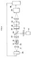
- Fig. 4 is a schematic diagram of an apparatus for analyzing particles in Embodiment 2.
- the apparatus in Fig. 4 is different from the apparatus in Fig. 1 in the configuration (arrangement) of the illumination system of the light source 10 (illumination system of fluorescence excitation light) and the scattered light detection system of the light (photo) detecting means 36, and the apparatus in Fig. 4 is intended to detect the forward scattered light and backward fluorescence.
- the excitation light from the light source 10 does not enter directly into the fluorescence detecting system, so that fluorescence measurement at high precision is realized.
- Fig. 5 is a schematic diagram of an apparatus for analyzing particles in Embodiment 3.
- the apparatus in Fig. 5 is further different from the apparatus in Fig. 4 in the arrangement of the scattered light detecting system of the light detecting means 36, and the apparatus in Fig. 5 is intended to detect the side scattered light and backward fluorescence.
- the shielding plate 20 for detecting the side scattered light is not needed.
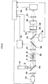
- Fig. 6 is a schematic diagram of an apparatus for analyzing particles in Embodiment 4.
- This embodiment shows an arrangement of an apparatus for picking up white light images of cells emitting fluorescence of a specific wavelength by utilizing the signal obtained in Embodiment 1.
- a pulse emission type light source in the visible light region for example, Xe flash lamp
- the irradiation light from the light source 40 is transformed into parallel light in a collimator lens 42, and enters a half-mirror 46.
- the half-mirror 46 is used for matching the irradiation regions of the excitation light source 10 and pickup light source 40, and the ratio of transmitted light and reflected light is determined freely by the quantity of light required in the fluorescence receiving system and cell pickup system, but it is desired to heighten the transmissivity of the light from the excitation light source 10 by setting the transmissivity at 90% and the reflectivity at 10% in order to intensify the fluorescence intensity.
- a half-mirror 48 is designed to pass the fluorescence obtained from the cell and reflect the cell pickup light, and the ratio of the reflected light and transmitted light can be determined according to the quantity of light required in each system, same as in the case of the half-mirror 46.
- An electronic shutter 50 is used to prevent excessive light from entering the image intensifier 30 when the cell image pickup light source 40 emits light. Instead of this electronic shutter, an image intensifier possessing a gate function may be used.
- the image pickup means for example a CCD camera 52, is intended to pick up the white light image of the cell.
- the excitation light is always entering the CCD camera, and the CCD element is saturated by the luminance (brightness), and therefore, as shown in Fig. 7, the irradiation region 56 of the excitation light source 10 and the pickup region 57 of the CCD camera 52 must be separate.
- Numeral 58 denotes a particle.
- the excitation light source 10 if the light source such as He-Cd laser for emitting the light in the wavelength outside the visible region or at the end of visible region is used, this light does not affect the color imaging of the cell.
- the signal processor 54 processes the signal from the light receiving element (image sensor) 34 and judges if the cell in the process of passing the pickup region is to be measured or not, and if judged to be the target cell a trigger pulse is generated to activate the cell image pickup light source 40, while the obtained signal is analyzed.
- the fluorescence excitation light source 10 always illuminates the particle passing region of the flow cell 16, and monitors passing of cells.
- a cell dyed with fluorescent dye passes, the fluorescence emitted from the cell and the remaining excitation light are condensed by the receiving lens 22, and pass through a half-mirror 48, and the excitation light component is removed by the dichroic mirror 24, and the remaining light passes through a circular slit 26, and enters the spectroscopic means 28.
- the fluorescence light entering the spectroscopic means 28 is separated into spectra, and passes through the electronic shutter 50, and a spectral image as shown in Fig. 3 is focused on the image intensifier 30.
- This spectral image is amplified by the image intensifier 30, and is output at the fluorescent plane of the image intensifier 30.
- the spectral image produced on the fluorescent plane of the image intensifier 30 is focused on the light receiving element 34 by the relay lens 32.
- the image instead of the relay lens 32, the image may be also focused on the light receiving element 34 by using an optical fiber.
- a similar effect is obtained when the electronic shutter 50 is disposed behind (downstream of) the spectroscopic means 28. Moreover, without using the electronic shutter 50, the same effect may be obtained by using an image intensifier with gate function.
- the detected signal is analyzed by the signal processor 54.
- the particle to be measured is dyed in FITC or phycoerythrin or in both, and hence the fluorescence wavelength emitted from the particle is either 530 nm or 570 nm, or both. Accordingly, when either one of the fluorescence intensity at 530 nm and 570 nm is more than a specific value or both are more than specific values, the white light image pickup light source 40 is activated.
- the pictured particle images are classified and stored according to fluorescence wavelength (in three types, that is, 530 nm, 570 nm, and both). Alternatively, comparing the measured fluorescence wavelength pattern with a preset fluorescence wavelength pattern, if the wavelength patterns are matched, the white light image pickup light source 40 is activated.
- the emission time of the white light image pickup light source 40 must be a sufficiently short time, otherwise the still image is not obtained. This emission time is determined by the velocity of the cell passing through the pickup region. For example, if the cell velocity is 1 m/sec, the emission time must be 1 ⁇ sec or less.
- the electronic shutter 50 is operated, so that strobe light may not enter the image intensifier 30.
- the light emitted from the white light image pickup light source 40 passes through the half-mirror 46, and irradiates the cell in the flow cell 16.
- the light passing through the cell is focused by the receiving lens 22, and is reflected by the half-mirror 48, and is focused on the CCD camera 52.
- the irradiation system of the fluorescence excitation light of the light source 10 and the irradiation system of pulse light for image pickup of the light source 40 are disposed on the same optical axis, and the detection systems of scattered light, fluorescence, and particle image light are disposed on the same optical axis so as to detect the forward scattered light, forward fluorescence and transmitted light image, but other embodiments may be also executed.
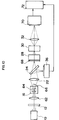
- Fig. 8 is a schematic diagram of an apparatus for analyzing particles in Embodiment 5.
- the apparatus in Fig. 8 is different from the apparatus in Fig. 6 in the arrangement of the irradiation system of fluorescence excitation light of the light source 10, and is intended to detect the side scattered light of the light source 10, side fluorescence of the light source 10, and transmitted light image of the light source 40.
- the shield plate 20 for detecting side scattered light is not needed.
- a half-mirror or dichroic mirror for reflecting the light from the light source 10 must be used as the mirror 46, and therefore the light from each light source cannot be led efficiently into the flow cell 16.
- mirror 46 since mirror 46 is not used, it is advantageous because the light from the light source 10 and the light from the light source 40 can be directly and efficiently irradiated at the flow cell 16.
- Fig. 9 is a schematic diagram of an apparatus for analyzing particles in Embodiment 6.
- the apparatus in Fig. 9 is different from the apparatus in Fig. 6 in the arrangement of the irradiation system of pulse light for particle pickup of the light source 40 and the pickup system of particle transmitted light image, and the apparatus in Fig. 9 is intended to detect the forward scattered light of the light source 10, forward fluorescence of the light source 10, and the transmitted light image of the light source 40.
- the system for picking up white light image is disposed at a position orthogonal to the optical system for detection of fluorescence.
- Numeral 15 is a condenser
- 23 is a receiving lens
- 60 is a signal processor.
- Fig. 10 is a schematic diagram of an apparatus for analyzing particles in Embodiment 7.
- the sample liquid flow is a flat flow 64, instead of a circular flow;
- the light receiving element for detecting the fluorescent spectral image is a two-dimensional image sensor 70, instead of a one-dimensional image sensor;
- the slit is a rectangular slit 68 broad (wide) in the lateral direction, instead of the circular one.
- Fig. 11 is a magnified view of essential parts of Fig. 10. Since the sample liquid flow 64 is a flat flow, the number of particles to be analyzed can be increased. Besides, using a two-dimensional image sensor 70, a spectral distribution diagram for each point in the X-direction may be obtained. Besides, in order to obtain a flat sample liquid flow 64 in the flow cell 16, the lead-in passage of the flow cell 16 is gradually narrowed in width only in one direction of the passage.
- the measuring region in the flow cell 16 For example, supposing the measuring region in the flow cell 16 to be 20 x 150 ⁇ m and the imaging magnification of receiving lens 22 to be 40 times, when the slit 68 before (upstream of) the spectroscopic means 28 is 6 x 0.8 mm, the size of one pixel is 40 ⁇ m in the light receiving element (two-dimensional image sensor) 70, and the CCD area sensor has 150 x 250 pixels (150 pixels in the X-direction, 250 pixels in the Y-direction), the fluorescent spectrum from the cell can be measured in the entire measuring region, and the wavelength resolution of 1 nm per 1 pixel of CCD can be attained.
- the wavelength of the fluorescence emitted simultaneously from a plurality of cells can be measured.
- the wavelength of the fluorescence emitted from the cells is limited in a specific wavelength region, for example, when using FITC (fluorescein isothiocyanate), phycoerythrin, and propidium iodine as fluorescent dyes, by placing the line type CCD sensor or photo diode array at the Y-axis position corresponding to the wavelengths of 530 nm, 570 nm, and 610 nm, only the intended spectral component can be measured.
- Numeral 62 is a condenser and 66 is a shield plate.
- Fig. 12 is a schematic diagram of an apparatus for analyzing particles in Embodiment 8.
- the system for white light image pickup is added to the apparatus of Embodiment 7 shown in Fig. 10.
- the signal obtained from the detector (two-dimensional image sensor) 70 is analyzed by the signal processor 74.
- the white light image pickup light source 40 is used to form a cell image in the CCD camera 52.
- Numeral 44 is a wavelength selection filter.
- the embodiments have the following characteristics.
Abstract
A sample liquid flow (18) contains particle components such as blood and urine and is illuminated with fluorescence excitation light from a light source (10). Spectral means (28) such as a prism or a diffraction grating is used to produce a spectrum of the fluorescence emitted by the particles. The fluorescence spectrum is amplified by an image intensifier (30). Then, the intensity of different wavelengths of the fluorescence spectrum is measured by an image sensor (34). The image sensor (34) is reset for each particle.
Description
- The present invention relates to apparatus for analyzing a sample liquid containing particles such as blood and urine, by irradiating the sample liquid with light, detecting signals from the particles, and analyzing the particles. The apparatus obtains spectra of light signals by using spectral means such as a prism or diffraction grating, so as to obtain more specific particle information.
- In the prior art, a fluorescent excitation (excited) light is irradiated at a sample liquid containing particles such as dyed cells, and the fluorescence emitted from the particles is detected, and the particles are classified and counted. An example of such apparatus is a flow cytometer. Also known is an imaging flow cytometer for picking up the particle images.
- In such apparatus, when measuring the fluorescence emitted from the cells, in order to separate the desired fluorescence from other light, wavelength selection means such as an optical filter and a dichroic mirror is needed. Besides, when measuring a plurality of fluorescences of different wavelengths, a corresponding plurality of optical detectors are needed.
- Japanese Laid-open Patent Hei. 2-24535 discloses a flow cytometer capable of calculating the fluorescence intensity distribution (intensity against wavelength) of the particles, by separating the fluorescence from the specimen into consecutive wavelength components by spectroscopic means, and detecting the separated wavelength components by using a one-dimensional photoelectric detector.
- With the optical filter, however, it is difficult to separate beams of light of similar wavelengths, although it is possible to separate beams of light of very different wavelengths. In addition, the wavelength distribution of the light cannot be measured. That is, it is not possible to know the quantity of fluorescence of a particular wavelength that is emitted from a particular position of a cell. This may be possible by taking the cell image by using a video camera and analyzing the image, but each cell must be imaged and the image processed. Thus, the apparatus becomes complicated.
- In the apparatus for analyzing particles disclosed in the Japanese Laid-open Patent Hei. 2-24535, moreover, since the separated fluorescence is weak, it is difficult to detect the fluorescence directly with the detector. By increasing the lighting (irradiation) intensity of the fluorescence excitation light, the fluorescence intensity may be enhanced, but the particles to be analyzed may become damaged.
- Besides, when using a photoelectric conversion element of charge accumulation type such as a charge coupled device (CCD), unless the accumulated charge is reset by some way or other, the fluorescence of all particles passing through the detection region is added up (integrated). Since the particle interval is not constant, it is necessary to detect the passing of a particle, and reset the charge on every occasion.
- According to the present invention, there is provided apparatus for analyzing particles, comprising: a first light source for illuminating with fluorescence excitation light a sample liquid flow containing particles; spectral means for separating fluorescence emitted in a specific direction from a particle to produce a fluorescence spectrum; amplifying means for amplifying the fluorescence spectrum produced by the spectral means; an image sensor for detecting different wavelengths of the amplified fluorescence spectrum; and signal processing means for receiving a signal from the image sensor and resetting the signal of the image sensor for each particle.
- With the invention, it is possible to analyze a particle by measuring the fluorescence spectrum with high precision even if the fluorescence emitted by the particle is of low intensity.
- Preferably, the sample liquid is formed into a sheath flow in which the suspension of particles is covered with a laminar sheath liquid in order to align the particles in a row near the middle of the liquid flow. Usually the sheath liquid is a diluent liquid or the like.
- The fluorescence emitted from the particle as a result of irradiation with the fluorescence excitation light is separated by the spectral means, and a fluorescence spectrum is obtained. This fluorescence spectrum is amplified by the amplifying means, such as an image intensifier, and the intensity of a range of wavelengths may be measured by the image sensor.
- If the image sensor comprises a plurality of rows or lines of one-dimensional images sensors, the fluorescence spectra of a plurality of particles can be measured simultaneously.
- If the fluorescence excitation light passing through the particle and the scattered light scattered by the particle are detected by a light detecting means, passage of the particle through a detection region may be judged by the signal processing means. In response to the passing of the particle, the signal of the image sensor is reset, before the signal is read out (if the particle is not of interest) or after the signal is read out (if the particle is of interest).
- Non-limiting embodiments of the invention will now be described with reference to the accompanying drawings, in which:-
- Fig. 1 is a schematic diagram showing an embodiment of an apparatus for analyzing particles in accordance with the invention;
- Fig. 2 is a characteristic diagram of dichroic mirror of Fig. 1;
- Fig. 3 is a perspective explanatory diagram showing the detail around the spectroscopic means of Fig. 1;
- Fig. 4 is a schematic diagram showing another embodiment of the invention;
- Fig. 5 is a schematic diagram showing another embodiment of the invention;
- Fig. 6 is a schematic diagram showing a different embodiment of the invention;
- Fig. 7 is an explanatory diagram showing an irradiation region of an excitation light source and an image pickup region of a CCD camera in a flow cell unit of Fig. 6;
- Fig. 8 is a schematic diagram showing another different embodiment of the invention;
- Fig. 9 is a schematic diagram showing another embodiment of the invention;
- Fig. 10 is a schematic diagram showing another embodiment of the invention;
- Fig. 11 is a perspective explanatory diagram showing the spectroscopic means of Fig. 10; and
- Fig. 12 is a schematic diagram showing another embodiment of the invention.
- Fig. 1 is a schematic diagram of an apparatus for analyzing particles in Embodiment 1.
- A
light source 10 is a fluorescence excitation (excited) light source, which is a laser light source such as Ar,He-Cd or semiconductor laser, or a light source of continuous emission type such as Xe lamp. When a light source with continuous spectrum such as Xe lamp is used, a desired excitation (excited) wavelength can be selected by using awavelength selection filter 12. When the laser light source is used, thefilter 12 is unnecessary. - A
condensing lens 14 is a lens for focusing the light from the fluorescenceexcitation light source 10 into a sampleliquid flow 18 flowing in the center of aflow cell 16, and the spot size when concentrated is desired to be about 10 x 200 µm. - The
flow cell 16 is made of transparent material of glass or plastics, and comprises a lead-in passage narrowed gradually, a narrow measuring passage connected to the lead-in passage, a sheath liquid feeding port provided in the lead-in passage, and a discharge port provided downstream of the measuring passage. - When the particle to be analyzed passes through the illumination region of the fluorescence excitation light, scattered light (forward scattered light) and fluorescence (forward fluorescence) are obtained. Both types of light are collected by a receiving
lens 22. Numeral 20 is a shield plate for shielding the direct light from thelight source 10. - The scattered light is reflected by a
dichroic mirror 24, and enters light detecting means, such as aCCD line sensor 36. The signal from theline sensor 36 is fed into thesignal processor 38, and passing of the particle is detected. At the same time, the size and number of passing particles are detected. When sensing the particle by the transmitted light, the shield plate must be removed. - On the other hand, the fluorescence passes through the
dichroic mirror 24 and through aslit 26 and enters thespectroscopic means 28. Fig. 2 shows the characteristic diagram of thedichroic mirror 24. - The
spectroscopic means 28 is for converting the fluorescence emitted from the cell into a spectrum. For example, by using polychromator, prism or lattice (grating), a fluorescence spectral image as shown in Fig. 3 is obtained on the incident plane of amplifying means, such asimage intensifier 30. Numeral 58 denotes a particle. - The
image intensifier 30 is a photoelectron multiplier, and is used for amplifying the fluorescence spectral image separated by thespectroscopic means 28. The fluorescence spectral image entering the incident plane (photoelectric plane) of theimage intensifier 30 is amplified, and sent out to an output plane (fluorescence plane) of theimage intensifier 30. Furthermore, the fluorescence spectral image sent out of theimage intensifier 30 is focused on a light receiving element (image sensor) 34 by arelay lens 32 or an optical fiber. - By using a CCD line sensor or a photo diode array as the light receiving element (image sensor) 34, the fluorescence intensity of each wavelength is measured. For example, using a CCD line sensor with 256 pixels of 13µm each, and measuring in the wavelength region from 400 to 656 nm, by properly setting the focal length of the
spectroscopic means 28, the fluorescence intensity can be measured at a resolution of 1 nm per pixel. - When a CCD line sensor is used as a light receiving element (image sensor) 34, since it is of charge accumulation type, i.e. different to a photo diode array, the accumulated charge must be reset by some way or other (otherwise the fluorescence intensity of all passing particles is counted (added) up). Accordingly, by making use of the signal from the
line sensor 36 as the light detector, the accumulated charge is read out after every passing of particle, and the charge is reset. Besides, by processing the signal from theline sensor 36, it is judged whether the particle is to be measured or not and,in the case of a particle not to be measured, the fluorescence spectral signal is reset from theCCD line sensor 34 before reading out to thesignal processor 38, so that only necessary data is taken in. - The obtained signal is processed by the
signal processor 38, and the spectral data may be obtained for every passing particle. - Because the excitation (excited) light and fluorescence light at the
light receiving element 34 differ in wavelength, the position of the pixel for each wavelength signal is different. Hence, filter for removing excitation light is not needed. - Besides, for limiting the detecting region in the
flow cell 16, circular orrectangular slit 26 must be installed. Since the size of theslit 26 is determined by the imaging magnification of the receivinglens 22, the size of theslit 26 may be 0.2 mm in diameter in the case of, for example, the detecting region in the flow cell being 2 µm in diameter and the imaging magnification of the receivinglens 22 being 10 times. - Thus is realized the flow cytometer capable of acquiring fluorescence in two or more types (kinds) of wavelengths by using one detecting system.
- The apparatus in Fig. 1 is designed to detect the forward scattered light and forward fluorescence caused by fluorescence excitation light from the
light source 10, but other embodiments can be also realized. - For example, Fig. 4 is a schematic diagram of an apparatus for analyzing particles in Embodiment 2.
- The apparatus in Fig. 4 is different from the apparatus in Fig. 1 in the configuration (arrangement) of the illumination system of the light source 10 (illumination system of fluorescence excitation light) and the scattered light detection system of the light (photo) detecting
means 36, and the apparatus in Fig. 4 is intended to detect the forward scattered light and backward fluorescence. - By the arrangement of the irradiation system and the
mirror 24, the excitation light from thelight source 10 does not enter directly into the fluorescence detecting system, so that fluorescence measurement at high precision is realized. - Fig. 5 is a schematic diagram of an apparatus for analyzing particles in Embodiment 3.
- The apparatus in Fig. 5 is further different from the apparatus in Fig. 4 in the arrangement of the scattered light detecting system of the
light detecting means 36, and the apparatus in Fig. 5 is intended to detect the side scattered light and backward fluorescence. The shieldingplate 20 for detecting the side scattered light is not needed. - In this case, too, the same effects as in the apparatus in Fig. 4 may be obtained. In addition, since the side scattered light is detected, a signal reflecting (influencing) the difference in the internal structure of particles may be obtained.
- Fig. 6 is a schematic diagram of an apparatus for analyzing particles in Embodiment 4.
- This embodiment shows an arrangement of an apparatus for picking up white light images of cells emitting fluorescence of a specific wavelength by utilizing the signal obtained in Embodiment 1. As the light source, in addition to the fluorescence
excitation light source 10, a pulse emission type light source in the visible light region (for example, Xe flash lamp) is used as a cell imagepickup light source 40. The irradiation light from thelight source 40 is transformed into parallel light in acollimator lens 42, and enters a half-mirror 46. - The half-
mirror 46 is used for matching the irradiation regions of theexcitation light source 10 and pickuplight source 40, and the ratio of transmitted light and reflected light is determined freely by the quantity of light required in the fluorescence receiving system and cell pickup system, but it is desired to heighten the transmissivity of the light from theexcitation light source 10 by setting the transmissivity at 90% and the reflectivity at 10% in order to intensify the fluorescence intensity. - A half-
mirror 48 is designed to pass the fluorescence obtained from the cell and reflect the cell pickup light, and the ratio of the reflected light and transmitted light can be determined according to the quantity of light required in each system, same as in the case of the half-mirror 46. - An
electronic shutter 50 is used to prevent excessive light from entering theimage intensifier 30 when the cell imagepickup light source 40 emits light. Instead of this electronic shutter, an image intensifier possessing a gate function may be used. - The image pickup means, for example a
CCD camera 52, is intended to pick up the white light image of the cell. However, if the pickup region of the CCD camera and the irradiation region of excitation light are overlapped, the excitation light is always entering the CCD camera, and the CCD element is saturated by the luminance (brightness), and therefore, as shown in Fig. 7, theirradiation region 56 of theexcitation light source 10 and thepickup region 57 of theCCD camera 52 must be separate.Numeral 58 denotes a particle. As theexcitation light source 10, if the light source such as He-Cd laser for emitting the light in the wavelength outside the visible region or at the end of visible region is used, this light does not affect the color imaging of the cell. - The
signal processor 54 processes the signal from the light receiving element (image sensor) 34 and judges if the cell in the process of passing the pickup region is to be measured or not, and if judged to be the target cell a trigger pulse is generated to activate the cell imagepickup light source 40, while the obtained signal is analyzed. - The measuring procedure is explained below.
- The fluorescence
excitation light source 10 always illuminates the particle passing region of theflow cell 16, and monitors passing of cells. When a cell dyed with fluorescent dye passes, the fluorescence emitted from the cell and the remaining excitation light are condensed by the receivinglens 22, and pass through a half-mirror 48, and the excitation light component is removed by thedichroic mirror 24, and the remaining light passes through acircular slit 26, and enters the spectroscopic means 28. The fluorescence light entering the spectroscopic means 28 is separated into spectra, and passes through theelectronic shutter 50, and a spectral image as shown in Fig. 3 is focused on theimage intensifier 30. This spectral image is amplified by theimage intensifier 30, and is output at the fluorescent plane of theimage intensifier 30. The spectral image produced on the fluorescent plane of theimage intensifier 30 is focused on thelight receiving element 34 by therelay lens 32. At this time, instead of therelay lens 32, the image may be also focused on thelight receiving element 34 by using an optical fiber. - A similar effect is obtained when the
electronic shutter 50 is disposed behind (downstream of) the spectroscopic means 28. Moreover, without using theelectronic shutter 50, the same effect may be obtained by using an image intensifier with gate function. - Afterwards, the detected signal is analyzed by the
signal processor 54. When the particle is double-dyed in FITC (fluorscein isothiocyanate) and phycoerythrin, the particle to be measured is dyed in FITC or phycoerythrin or in both, and hence the fluorescence wavelength emitted from the particle is either 530 nm or 570 nm, or both. Accordingly, when either one of the fluorescence intensity at 530 nm and 570 nm is more than a specific value or both are more than specific values, the white light imagepickup light source 40 is activated. Furthermore, the pictured particle images are classified and stored according to fluorescence wavelength (in three types, that is, 530 nm, 570 nm, and both). Alternatively, comparing the measured fluorescence wavelength pattern with a preset fluorescence wavelength pattern, if the wavelength patterns are matched, the white light imagepickup light source 40 is activated. - To pick up a still cell image, the emission time of the white light image
pickup light source 40 must be a sufficiently short time, otherwise the still image is not obtained. This emission time is determined by the velocity of the cell passing through the pickup region. For example, if the cell velocity is 1 m/sec, the emission time must be 1 µsec or less. - At the same time,the
electronic shutter 50 is operated, so that strobe light may not enter theimage intensifier 30. - The light emitted from the white light image
pickup light source 40 passes through the half-mirror 46, and irradiates the cell in theflow cell 16. As a result, the light passing through the cell is focused by the receivinglens 22, and is reflected by the half-mirror 48, and is focused on theCCD camera 52. - In this way, the white light image of the cell emitting fluorescence of a specific wavelength is acquired.
- In the apparatus shown in Fig. 6, the irradiation system of the fluorescence excitation light of the
light source 10, and the irradiation system of pulse light for image pickup of thelight source 40 are disposed on the same optical axis, and the detection systems of scattered light, fluorescence, and particle image light are disposed on the same optical axis so as to detect the forward scattered light, forward fluorescence and transmitted light image, but other embodiments may be also executed. - For example, Fig. 8 is a schematic diagram of an apparatus for analyzing particles in Embodiment 5.
- The apparatus in Fig. 8 is different from the apparatus in Fig. 6 in the arrangement of the irradiation system of fluorescence excitation light of the
light source 10, and is intended to detect the side scattered light of thelight source 10, side fluorescence of thelight source 10, and transmitted light image of thelight source 40. Theshield plate 20 for detecting side scattered light is not needed. - Moreover, in the arrangement of the apparatus in Fig. 6, when both the light of the
light source 10 and light oflight source 40 are visible, a half-mirror or dichroic mirror for reflecting the light from thelight source 10 must be used as themirror 46, and therefore the light from each light source cannot be led efficiently into theflow cell 16. However, in the arrangement of the apparatus in Fig. 8, sincemirror 46 is not used, it is advantageous because the light from thelight source 10 and the light from thelight source 40 can be directly and efficiently irradiated at theflow cell 16. - Fig. 9 is a schematic diagram of an apparatus for analyzing particles in Embodiment 6.
- The apparatus in Fig. 9 is different from the apparatus in Fig. 6 in the arrangement of the irradiation system of pulse light for particle pickup of the
light source 40 and the pickup system of particle transmitted light image, and the apparatus in Fig. 9 is intended to detect the forward scattered light of thelight source 10, forward fluorescence of thelight source 10, and the transmitted light image of thelight source 40. - In this embodiment, compared with the apparatus for analyzing particles in Embodiment 4, the system for picking up white light image is disposed at a position orthogonal to the optical system for detection of fluorescence.
- In this arrangement, since it is not necessary to use the half-
mirrors light sources Numeral 15 is a condenser, 23 is a receiving lens, and 60 is a signal processor. - Fig. 10 is a schematic diagram of an apparatus for analyzing particles in Embodiment 7.
- The basic arrangement of this embodiment is the same as Embodiment 1. The differences of this embodiment are as follows: 1. the sample liquid flow is a
flat flow 64, instead of a circular flow; 2. the light receiving element for detecting the fluorescent spectral image is a two-dimensional image sensor 70, instead of a one-dimensional image sensor; 3. the slit is arectangular slit 68 broad (wide) in the lateral direction, instead of the circular one. - Fig. 11 is a magnified view of essential parts of Fig. 10. Since the
sample liquid flow 64 is a flat flow, the number of particles to be analyzed can be increased. Besides, using a two-dimensional image sensor 70, a spectral distribution diagram for each point in the X-direction may be obtained. Besides, in order to obtain a flatsample liquid flow 64 in theflow cell 16, the lead-in passage of theflow cell 16 is gradually narrowed in width only in one direction of the passage. - For example, supposing the measuring region in the
flow cell 16 to be 20 x 150 µm and the imaging magnification of receivinglens 22 to be 40 times, when theslit 68 before (upstream of) the spectroscopic means 28 is 6 x 0.8 mm, the size of one pixel is 40µm in the light receiving element (two-dimensional image sensor) 70, and the CCD area sensor has 150 x 250 pixels (150 pixels in the X-direction, 250 pixels in the Y-direction), the fluorescent spectrum from the cell can be measured in the entire measuring region, and the wavelength resolution of 1 nm per 1 pixel of CCD can be attained. - Herein, by processing the signal obtained from the
light receiving element 70 by thesignal processor 72, the wavelength of the fluorescence emitted simultaneously from a plurality of cells can be measured. - Besides, when the wavelength of the fluorescence emitted from the cells is limited in a specific wavelength region, for example, when using FITC (fluorescein isothiocyanate), phycoerythrin, and propidium iodine as fluorescent dyes, by placing the line type CCD sensor or photo diode array at the Y-axis position corresponding to the wavelengths of 530 nm, 570 nm, and 610 nm, only the intended spectral component can be measured.
Numeral 62 is a condenser and 66 is a shield plate. - Fig. 12 is a schematic diagram of an apparatus for analyzing particles in Embodiment 8.
- In this embodiment, the system for white light image pickup is added to the apparatus of Embodiment 7 shown in Fig. 10. In this arrangement, the signal obtained from the detector (two-dimensional image sensor) 70 is analyzed by the
signal processor 74. When a cell emitting fluorescence coinciding with predetermined conditions is detected (for example, when double-dyed in fluorescein isothiocyanate and phycoeryrhin, and either 530 nm or 570 nm fluorescence intensity is more than a specific value, or when both are more than specific values), the white light imagepickup light source 40 is used to form a cell image in theCCD camera 52.Numeral 44 is a wavelength selection filter. - In the embodiments in which the sample liquid flow is a flat flow, it is possible to vary the arrangement of the optical system.
- Being thus constructed, the embodiments have the following characteristics.
- (1) The fluorescence from the spectroscopic means such as a prism or a diffraction grating is separated by wavelength, and amplified by an image intensifier, and the intensity is measured by an image sensor at each wavelength, and therefore a plurality of fluorescence intensities can be measured simultaneously for individual particles with high precision. Besides, a fluorescent spectral image can be obtained.
- (2) The light is separated by spectroscopic means, instead of wavelength selection filter, so that it is possible to separate clearly if the wavelengths are close to each other
- (3) When the sample liquid flow is a flat flow, and a two-dimensional image sensor is used as an image sensor, the fluorescent spectra of a plurality of particles can be measured at the same time.
- Having described preferred embodiments of the invention with reference to the accompanying drawings, it is to be understood that the invention is not limited to those precise embodiments, and that various changes and modifications may be effected thereto by one skilled in the art without departing from the invention.
Claims (11)
- Apparatus for analyzing particles, comprising:
a first light source (10) for illuminating with fluorescence excitation light a sample liquid flow (18) containing particles;
spectral means (28) for separating fluorescence emitted in a specific direction from a particle to produce a fluorescence spectrum;
amplifying means (30) for amplifying the fluorescence spectrum produced by the spectral means (28);
an image sensor (34) for detecting different wavelengths of the amplified fluorescence spectrum; and
signal processing means (38) for receiving a signal from the image sensor (34) and resetting the signal of the image sensor for each particle. - Apparatus for analyzing particles according to claim 1, further comprising light detecting means (36) for detecting light scattered by the particle or transmitted light passing through the particle.
- Apparatus for analyzing particles according to claim 2, wherein the light detecting means (36) is disposed to detect forward scattered light and forward fluorescence.
- Apparatus for analyzing particles according to claim 2, wherein the light detecting means (36) is disposed to detect forward scattered light and backward fluorescence.
- Apparatus for analyzing particles according to claim 2, wherein the light detecting means (36) is disposed to detect side scattered light and backward fluorescence.
- Apparatus for analyzing particles according to any one of claims 1 to 5, further comprising a second light source (40) for emitting a pulse of light at the particle, and image pickup means (52) for picking up an image produced by transmitted pulse light passing through the particle.
- Apparatus for analyzing particles according to claim 6, wherein the optical path from the sample liquid flow (18) to the spectral means (28) has, at least initially, the same optical axis as the optical path from the sample liquid flow (18) to the image pickup means (52).
- Apparatus for analyzing particles according to claim 6, wherein the optical path from the sample liquid flow (18) to the spectral means (28) is, at least initially, substantially orthogonal to the optical path from the sample liquid flow (18) to the image pickup means (52).
- Apparatus for analyzing particles according to claim 6, 7 or 8, wherein the optical path from the first light source (10) to the sample liquid flow (18) is, at least adjacent to the sample liquid flow (18), substantially orthogonal to the optical path from the second light source (40) to the sample liquid flow (18).
- Apparatus for analyzing particles according to any one of claims 1 to 9, wherein:
the apparatus is arranged to form a sheath flow by enveloping the sample liquid flow (64) with a sheath liquid and to pass the sheath flow through a flow cell (16);
the sample liquid flow (64) is a flat flow wide in one direction and narrow in another direction;
the spectral means (28) is arranged to separate fluorescence emitted from one of the wide sides of the flat sample liquid flow (64); and
the image sensor is a two-dimensional image sensor (70). - Apparatus for analyzing particles according to claims 2 and 10, wherein the light detecting means (36) is arranged to detect light scattered by the particle out of one of the wide sides of the flat sample liquid flow (64) or transmitted light passing through the particle.
Applications Claiming Priority (2)
| Application Number | Priority Date | Filing Date | Title |
|---|---|---|---|
| JP10882892 | 1992-04-01 | ||
| JP108828/92 | 1992-04-01 |
Publications (1)
| Publication Number | Publication Date |
|---|---|
| EP0564157A1 true EP0564157A1 (en) | 1993-10-06 |
Family
ID=14494579
Family Applications (1)
| Application Number | Title | Priority Date | Filing Date |
|---|---|---|---|
| EP93302265A Withdrawn EP0564157A1 (en) | 1992-04-01 | 1993-03-25 | Apparatus for analyzing particles |
Country Status (2)
| Country | Link |
|---|---|
| US (1) | US5422712A (en) |
| EP (1) | EP0564157A1 (en) |
Cited By (12)
| Publication number | Priority date | Publication date | Assignee | Title |
|---|---|---|---|---|
| WO1995021242A1 (en) * | 1994-02-07 | 1995-08-10 | Whitbread Plc | Monitoring the colour and bitterness of beer |
| WO1999015877A1 (en) * | 1997-09-22 | 1999-04-01 | Neles Field Controls Oy | Method and instrument for measuring fibres in suspension |
| WO1999056106A1 (en) * | 1998-04-29 | 1999-11-04 | Particle Measuring Systems, Inc. | Chemical-mechanical-planarization (cmp) slurry quality control process and particle size distribution measuring systems |
| US6087182A (en) * | 1998-08-27 | 2000-07-11 | Abbott Laboratories | Reagentless analysis of biological samples |
| WO2005074506A2 (en) | 2004-01-30 | 2005-08-18 | Nalco Company | Interchangeable tip-open cell fluorometer |
| WO2012104496A1 (en) * | 2011-02-04 | 2012-08-09 | Horiba Abx Sas | Device and method for multiparametric measurements of microparticles in a fluid |
| CN101435764B (en) * | 2007-11-12 | 2013-11-27 | 北京深迈瑞医疗电子技术研究院有限公司 | Particle analyzer and particle analysis method |
| EP2327977A3 (en) * | 2009-11-30 | 2017-08-23 | Sysmex Corporation | Particle analyzing apparatus and particle imaging method |
| CN107525585A (en) * | 2011-09-13 | 2017-12-29 | 索尼公司 | The method that spectral analysis apparatus, spectroscopic analysis methods and spectrogram are shown |
| EP3259574A4 (en) * | 2015-02-18 | 2018-10-31 | Becton, Dickinson and Company | Optical detection systems and methods of using the same |
| CN112229822A (en) * | 2020-08-25 | 2021-01-15 | 西安电子科技大学 | Reflection type single-frame scattering imaging device and method for multiple targets in flowing liquid |
| CN113508286A (en) * | 2019-03-21 | 2021-10-15 | 贝克顿·迪金森公司 | Light detection system and method of use |
Families Citing this family (65)
| Publication number | Priority date | Publication date | Assignee | Title |
|---|---|---|---|---|
| CN1087429C (en) * | 1994-03-04 | 2002-07-10 | 株式会社京都第一科学 | Method of and apparatus for measuring uric components |
| JPH08275063A (en) * | 1995-04-04 | 1996-10-18 | Minolta Co Ltd | Image pickup device |
| DE19906757B4 (en) * | 1998-02-19 | 2004-07-15 | Leica Microsystems Heidelberg Gmbh | microscope |
| US6075609A (en) * | 1998-03-26 | 2000-06-13 | Antek Industrial Instruments, Inc. | Apparatus and methods for improving fluorescence detectors |
| DE19936573A1 (en) * | 1998-12-22 | 2001-02-08 | Zeiss Carl Jena Gmbh | Arrangement for the separation of excitation and emission light in a microscope |
| DE19859314A1 (en) * | 1998-12-22 | 2000-06-29 | Zeiss Carl Jena Gmbh | Light diffraction device for separating excitation and emission light in confocal microscope e.g. laser scanning microscope, uses at least one diffraction element for diffraction of selected wavelength of excitation light |
| US6580504B1 (en) | 1999-01-25 | 2003-06-17 | Amnis Corporation | Multipass cavity for illumination and excitation of moving objects |
| US6249341B1 (en) | 1999-01-25 | 2001-06-19 | Amnis Corporation | Imaging and analyzing parameters of small moving objects such as cells |
| US7450229B2 (en) * | 1999-01-25 | 2008-11-11 | Amnis Corporation | Methods for analyzing inter-cellular phenomena |
| US8406498B2 (en) * | 1999-01-25 | 2013-03-26 | Amnis Corporation | Blood and cell analysis using an imaging flow cytometer |
| US8131053B2 (en) * | 1999-01-25 | 2012-03-06 | Amnis Corporation | Detection of circulating tumor cells using imaging flow cytometry |
| US20060257884A1 (en) * | 2004-05-20 | 2006-11-16 | Amnis Corporation | Methods for preparing and analyzing cells having chromosomal abnormalities |
| US6473176B2 (en) | 1999-01-25 | 2002-10-29 | Amnis Corporation | Imaging and analyzing parameters of small moving objects such as cells |
| US6975400B2 (en) * | 1999-01-25 | 2005-12-13 | Amnis Corporation | Imaging and analyzing parameters of small moving objects such as cells |
| US6608682B2 (en) | 1999-01-25 | 2003-08-19 | Amnis Corporation | Imaging and analyzing parameters of small moving objects such as cells |
| US7057732B2 (en) * | 1999-01-25 | 2006-06-06 | Amnis Corporation | Imaging platform for nanoparticle detection applied to SPR biomolecular interaction analysis |
| US8885913B2 (en) | 1999-01-25 | 2014-11-11 | Amnis Corporation | Detection of circulating tumor cells using imaging flow cytometry |
| US6671044B2 (en) | 1999-01-25 | 2003-12-30 | Amnis Corporation | Imaging and analyzing parameters of small moving objects such as cells in broad flat flow |
| US6707551B2 (en) * | 2000-01-24 | 2004-03-16 | Amnis Corporation | Multipass cavity for illumination and excitation of moving objects |
| US8264680B2 (en) * | 1999-05-28 | 2012-09-11 | Yokogawa Electric Corporation | Biochip reader and electrophoresis system |
| EP1055925B1 (en) * | 1999-05-28 | 2010-09-08 | Yokogawa Electric Corporation | Biochip reader |
| US6778263B2 (en) * | 2000-08-25 | 2004-08-17 | Amnis Corporation | Methods of calibrating an imaging system using calibration beads |
| US6875973B2 (en) * | 2000-08-25 | 2005-04-05 | Amnis Corporation | Auto focus for a flow imaging system |
| US6583865B2 (en) | 2000-08-25 | 2003-06-24 | Amnis Corporation | Alternative detector configuration and mode of operation of a time delay integration particle analyzer |
| US6608680B2 (en) | 2000-08-25 | 2003-08-19 | Amnis Corporation | TDI imaging system for kinetic studies |
| US6934408B2 (en) * | 2000-08-25 | 2005-08-23 | Amnis Corporation | Method and apparatus for reading reporter labeled beads |
| WO2002017219A1 (en) * | 2000-08-25 | 2002-02-28 | Amnis Corporation | Measuring the velocity of small moving objects such as cells |
| AU2002213157A1 (en) | 2000-10-12 | 2002-04-22 | Amnis Corporation | System and method for high numeric aperture imaging systems |
| AU2002211913A1 (en) | 2000-10-12 | 2002-04-22 | Amnis Corporation | Multipass cavity for illumination and excitation of moving objects |
| US20020146734A1 (en) * | 2001-02-21 | 2002-10-10 | Amnis Corporation | Method and apparatus for labeling and analyzing cellular components |
| EP1389956B1 (en) * | 2001-04-25 | 2012-10-31 | Amnis Corporation | Method and apparatus for correcting crosstalk and spatial resolution for multichannel imaging |
| US7190832B2 (en) | 2001-07-17 | 2007-03-13 | Amnis Corporation | Computational methods for the segmentation of images of objects from background in a flow imaging instrument |
| US6941005B2 (en) * | 2002-11-01 | 2005-09-06 | Coulter International Corp. | Monitoring and control of droplet sorting |
| JP2005006553A (en) * | 2003-06-19 | 2005-01-13 | Olympus Corp | Apparatus for cell culture detection |
| US8953866B2 (en) | 2004-03-16 | 2015-02-10 | Amnis Corporation | Method for imaging and differential analysis of cells |
| EP1800124B1 (en) | 2004-03-16 | 2011-12-21 | Amnis Corporation | Image based quantitation of molecular translocation |
| EP1725854B1 (en) | 2004-03-16 | 2019-05-08 | Luminex Corporation | Method for imaging and differential analysis of cells |
| US7280204B2 (en) * | 2004-04-08 | 2007-10-09 | Purdue Research Foundation | Multi-spectral detector and analysis system |
| WO2007067999A2 (en) * | 2005-12-09 | 2007-06-14 | Amnis Corporation | Extended depth of field imaging for high speed object analysis |
| JP4763485B2 (en) * | 2006-03-15 | 2011-08-31 | 株式会社日立ハイテクノロジーズ | Fluorescence detection device |
| WO2008019448A1 (en) * | 2006-08-18 | 2008-02-21 | Macquarie University | Time gated fluorescent flow cytometer |
| DE102007027008A1 (en) * | 2007-06-08 | 2008-12-11 | Spectro Analytical Instruments Gmbh & Co. Kg | Spectrometers with solid state sensors and secondary electron multipliers |
| US8039817B2 (en) | 2008-05-05 | 2011-10-18 | Illumina, Inc. | Compensator for multiple surface imaging |
| US9322761B2 (en) | 2009-08-13 | 2016-04-26 | Siemens Healthcare Diagnostics Inc. | Methods and apparatus for ascertaining interferents and physical dimensions in liquid samples and containers to be analyzed by a clinical analyzer |
| US8451524B2 (en) * | 2009-09-29 | 2013-05-28 | Amnis Corporation | Modifying the output of a laser to achieve a flat top in the laser's Gaussian beam intensity profile |
| US8817115B1 (en) | 2010-05-05 | 2014-08-26 | Amnis Corporation | Spatial alignment of image data from a multichannel detector using a reference image |
| CN103308440A (en) * | 2013-05-28 | 2013-09-18 | 香港浸会大学深圳研究院 | Flow type fluorescence microscopy imaging device and method |
| US9352315B2 (en) | 2013-09-27 | 2016-05-31 | Taiwan Semiconductor Manufacturing Company, Ltd. | Method to produce chemical pattern in micro-fluidic structure |
| US9261452B2 (en) * | 2013-12-23 | 2016-02-16 | Palo Alto Research Center Incorporated | Flow cytometer |
| US10324020B2 (en) | 2013-12-23 | 2019-06-18 | Palo Alto Research Center Incorporated | Fluidic optical cartridge |
| JP6325423B2 (en) * | 2014-10-10 | 2018-05-16 | アズビル株式会社 | Liquid fluorescence detection apparatus and liquid fluorescence detection method |
| WO2017145816A1 (en) * | 2016-02-24 | 2017-08-31 | ソニー株式会社 | Optical measuring instrument, flow cytometer and radiation counter |
| US11293817B2 (en) | 2017-01-06 | 2022-04-05 | Newtonoid Technologies, L.L.C. | Transparent ceramic composition |
| WO2018129360A1 (en) * | 2017-01-06 | 2018-07-12 | Newtonoid Technologies, L.L.C. | Transparent ceramic composition |
| CN110621978B (en) | 2017-02-27 | 2023-07-11 | 贝克顿·迪金森公司 | Light detection system and method of using the same |
| WO2019195685A1 (en) | 2018-04-05 | 2019-10-10 | Newtonoid Technologies, L.L.C. | Thin-walled changing displays |
| US10704094B1 (en) | 2018-11-14 | 2020-07-07 | Element Biosciences, Inc. | Multipart reagents having increased avidity for polymerase binding |
| US10876148B2 (en) | 2018-11-14 | 2020-12-29 | Element Biosciences, Inc. | De novo surface preparation and uses thereof |
| US10768173B1 (en) | 2019-09-06 | 2020-09-08 | Element Biosciences, Inc. | Multivalent binding composition for nucleic acid analysis |
| WO2020118255A1 (en) | 2018-12-07 | 2020-06-11 | Element Biosciences, Inc. | Flow cell device and use thereof |
| US20220244164A1 (en) * | 2019-05-30 | 2022-08-04 | Sony Group Corporation | Optical measuring device and optical measuring system |
| US11287422B2 (en) | 2019-09-23 | 2022-03-29 | Element Biosciences, Inc. | Multivalent binding composition for nucleic acid analysis |
| US20220067953A1 (en) * | 2020-09-02 | 2022-03-03 | International Business Machines Corporation | Reflection-based monoscopic depth perception |
| EP4012377B1 (en) * | 2020-12-09 | 2024-04-24 | Wilde, Axel | Device and method for the detection of particles in fluid mixtures and gas mixtures |
| WO2023158817A1 (en) * | 2022-02-18 | 2023-08-24 | The Johns Hopkins University | Fluid analysis system and methods |
Citations (8)
| Publication number | Priority date | Publication date | Assignee | Title |
|---|---|---|---|---|
| JPS63233353A (en) * | 1987-03-20 | 1988-09-29 | Seiko Instr & Electronics Ltd | Flow site meter |
| US4793705A (en) * | 1987-10-07 | 1988-12-27 | The United States Of America As Represented By The United States Department Of Energy | Single molecule tracking |
| JPH0224535A (en) * | 1988-07-12 | 1990-01-26 | Canon Inc | Particle analyzing apparatus |
| EP0442025A1 (en) * | 1990-02-08 | 1991-08-21 | Toa Medical Electronics Co., Ltd. | Optical particle analyzing apparatus having two types of light sources |
| JPH03252542A (en) * | 1990-03-02 | 1991-11-11 | Hitachi Ltd | Immunoassey and device thereof |
| EP0466168A2 (en) * | 1990-07-13 | 1992-01-15 | Toa Medical Electronics Co., Ltd. | Particle image analyzing apparatus |
| JPH0465654A (en) * | 1990-07-05 | 1992-03-02 | Hitachi Ltd | Cell analysis apparatus |
| JPH0486546A (en) * | 1990-07-27 | 1992-03-19 | Canon Inc | Specimen inspection device |
Family Cites Families (10)
| Publication number | Priority date | Publication date | Assignee | Title |
|---|---|---|---|---|
| JPS59182341A (en) * | 1983-03-31 | 1984-10-17 | Horiba Ltd | Apparatus for measuring anisotropy of sample luminescence |
| US4690561A (en) * | 1985-01-18 | 1987-09-01 | Canon Kabushiki Kaisha | Particle analyzing apparatus |
| JPH0617861B2 (en) * | 1985-02-04 | 1994-03-09 | 株式会社日立製作所 | Particle density measuring device |
| US4988619A (en) * | 1987-11-30 | 1991-01-29 | United States Department Of Energy | Flow cytometry apparatus |
| US5123731A (en) * | 1988-02-01 | 1992-06-23 | Canon Kabushiki Kaisha | Particle measuring device |
| NO894680L (en) * | 1989-11-24 | 1991-05-27 | Flowtech A S V Harald Steen | PULSE MODULATION OF THE EXITATION LIGHT SOURCE IN LIQUID CURRENCY PHOTOMETERS. |
| JPH0734012B2 (en) * | 1991-02-27 | 1995-04-12 | 東亜医用電子株式会社 | Flow image cytometer |
| JP3084295B2 (en) * | 1991-02-27 | 2000-09-04 | シスメックス株式会社 | Flow image cytometer |
| EP0519092A1 (en) * | 1991-06-18 | 1992-12-23 | Sovetsko- Amerikanskoe Sovmestnoe Predpriyatie " Dialog" | Apparatus for determining space and time characteristics of the low optical emission of an object |
| JP3102935B2 (en) * | 1991-11-20 | 2000-10-23 | シスメックス株式会社 | Imaging flow cytometer |
-
1993
- 1993-03-18 US US08/034,376 patent/US5422712A/en not_active Expired - Fee Related
- 1993-03-25 EP EP93302265A patent/EP0564157A1/en not_active Withdrawn
Patent Citations (8)
| Publication number | Priority date | Publication date | Assignee | Title |
|---|---|---|---|---|
| JPS63233353A (en) * | 1987-03-20 | 1988-09-29 | Seiko Instr & Electronics Ltd | Flow site meter |
| US4793705A (en) * | 1987-10-07 | 1988-12-27 | The United States Of America As Represented By The United States Department Of Energy | Single molecule tracking |
| JPH0224535A (en) * | 1988-07-12 | 1990-01-26 | Canon Inc | Particle analyzing apparatus |
| EP0442025A1 (en) * | 1990-02-08 | 1991-08-21 | Toa Medical Electronics Co., Ltd. | Optical particle analyzing apparatus having two types of light sources |
| JPH03252542A (en) * | 1990-03-02 | 1991-11-11 | Hitachi Ltd | Immunoassey and device thereof |
| JPH0465654A (en) * | 1990-07-05 | 1992-03-02 | Hitachi Ltd | Cell analysis apparatus |
| EP0466168A2 (en) * | 1990-07-13 | 1992-01-15 | Toa Medical Electronics Co., Ltd. | Particle image analyzing apparatus |
| JPH0486546A (en) * | 1990-07-27 | 1992-03-19 | Canon Inc | Specimen inspection device |
Non-Patent Citations (5)
| Title |
|---|
| PATENT ABSTRACTS OF JAPAN vol. 13, no. 35 (P-818)26 January 1989 & JP-A-63 233 353 ( SEIKO ) 29 September 1988 * |
| PATENT ABSTRACTS OF JAPAN vol. 14, no. 169 (P-1032)30 March 1990 & JP-A-02 024 535 ( CANON ) 26 January 1990 * |
| PATENT ABSTRACTS OF JAPAN vol. 16, no. 264 (P-1370)15 June 1992 & JP-A-04 065 654 ( HITACHI ) 2 March 1992 * |
| PATENT ABSTRACTS OF JAPAN vol. 16, no. 309 (P-1382)8 July 1992 & JP-A-04 086 546 ( CANON ) 19 March 1992 * |
| PATENT ABSTRACTS OF JAPAN vol. 16, no. 53 (P-1309)10 February 1992 & JP-A-03 252 542 ( HITACHI ) 11 November 1991 * |
Cited By (32)
| Publication number | Priority date | Publication date | Assignee | Title |
|---|---|---|---|---|
| AU677147B2 (en) * | 1994-02-07 | 1997-04-10 | Whitbread Plc | Monitoring the colour and bitterness of beer |
| US5716850A (en) * | 1994-02-07 | 1998-02-10 | Whitbread Plc | Monitoring the colour and bitterness of beer |
| WO1995021242A1 (en) * | 1994-02-07 | 1995-08-10 | Whitbread Plc | Monitoring the colour and bitterness of beer |
| US6311550B1 (en) | 1997-09-22 | 2001-11-06 | Metso Field Systems Oy | Method for measuring particles in suspension and measuring instrument |
| WO1999015877A1 (en) * | 1997-09-22 | 1999-04-01 | Neles Field Controls Oy | Method and instrument for measuring fibres in suspension |
| US6246474B1 (en) | 1998-04-29 | 2001-06-12 | Particle Measuring Systems, Inc. | Method and apparatus for measurement of particle size distribution in substantially opaque slurries |
| USRE39783E1 (en) | 1998-04-29 | 2007-08-21 | Particle Measuring Systems, Inc. | Chemical mechanical planarization (CMP) slurry quality control process and particle size distribution measuring systems |
| US6275290B1 (en) | 1998-04-29 | 2001-08-14 | Particle Measuring Systems, Inc. | Chemical mechanical planarization (CMP) slurry quality control process and particle size distribution measuring systems |
| WO1999056106A1 (en) * | 1998-04-29 | 1999-11-04 | Particle Measuring Systems, Inc. | Chemical-mechanical-planarization (cmp) slurry quality control process and particle size distribution measuring systems |
| US6087182A (en) * | 1998-08-27 | 2000-07-11 | Abbott Laboratories | Reagentless analysis of biological samples |
| US6365109B1 (en) | 1998-08-27 | 2002-04-02 | Abbott Laboratories | Reagentless analysis of biological samples |
| US6426045B1 (en) | 1998-08-27 | 2002-07-30 | Abbott Laboratories | Reagentless analysis of biological samples |
| US6773922B2 (en) | 1998-08-27 | 2004-08-10 | Abbott Laboratories | Reagentless analysis of biological samples |
| EP2267435A1 (en) | 2004-01-30 | 2010-12-29 | Nalco Company | Interchangeable Tip-Open Cell Fluorometer |
| EP1718953A4 (en) * | 2004-01-30 | 2008-02-20 | Nalco Co | Interchangeable tip-open cell fluorometer |
| WO2005074506A2 (en) | 2004-01-30 | 2005-08-18 | Nalco Company | Interchangeable tip-open cell fluorometer |
| EP1718953A2 (en) * | 2004-01-30 | 2006-11-08 | Nalco Company | Interchangeable tip-open cell fluorometer |
| CN101435764B (en) * | 2007-11-12 | 2013-11-27 | 北京深迈瑞医疗电子技术研究院有限公司 | Particle analyzer and particle analysis method |
| EP2327977A3 (en) * | 2009-11-30 | 2017-08-23 | Sysmex Corporation | Particle analyzing apparatus and particle imaging method |
| FR2971337A1 (en) * | 2011-02-04 | 2012-08-10 | Horiba Abx Sas | DEVICE AND METHOD FOR MULTIPARAMETRIC MEASUREMENTS OF MICROPARTICLES IN A FLUID |
| CN103339489A (en) * | 2011-02-04 | 2013-10-02 | 赫拉巴Abx公司 | Device and method for multiparametric measurements of microparticles in a fluid |
| US9140645B2 (en) | 2011-02-04 | 2015-09-22 | Horiba Abx Sas | Device and method for multiparametric measurements of microparticles in a fluid |
| WO2012104496A1 (en) * | 2011-02-04 | 2012-08-09 | Horiba Abx Sas | Device and method for multiparametric measurements of microparticles in a fluid |
| CN107525585A (en) * | 2011-09-13 | 2017-12-29 | 索尼公司 | The method that spectral analysis apparatus, spectroscopic analysis methods and spectrogram are shown |
| CN107525585B (en) * | 2011-09-13 | 2020-09-18 | 索尼公司 | Spectrum analysis apparatus, spectrum analysis method, and method of displaying spectrogram |
| EP3259574A4 (en) * | 2015-02-18 | 2018-10-31 | Becton, Dickinson and Company | Optical detection systems and methods of using the same |
| US10184879B2 (en) | 2015-02-18 | 2019-01-22 | Becton, Dickinson And Company | Optical detection systems and methods of using the same |
| CN113508286A (en) * | 2019-03-21 | 2021-10-15 | 贝克顿·迪金森公司 | Light detection system and method of use |
| EP3942279A4 (en) * | 2019-03-21 | 2022-12-28 | Becton, Dickinson and Company | Light detection systems and methods of use thereof |
| US11953420B2 (en) | 2019-03-21 | 2024-04-09 | Becton, Dickinson And Company | Light detection systems and methods of use thereof |
| CN112229822A (en) * | 2020-08-25 | 2021-01-15 | 西安电子科技大学 | Reflection type single-frame scattering imaging device and method for multiple targets in flowing liquid |
| CN112229822B (en) * | 2020-08-25 | 2022-05-13 | 西安电子科技大学 | Reflection type single-frame scattering imaging device and method for multiple targets in flowing liquid |
Also Published As
| Publication number | Publication date |
|---|---|
| US5422712A (en) | 1995-06-06 |
Similar Documents
| Publication | Publication Date | Title |
|---|---|---|
| US5422712A (en) | Apparatus for measuring fluorescent spectra of particles in a flow | |
| US5644388A (en) | Imaging flow cytometer nearly simultaneously capturing a plurality of images | |
| JP3260469B2 (en) | Particle analyzer | |
| EP0501005B1 (en) | Flow imaging cytometer | |
| EP0501006B1 (en) | Flow imaging cytometer | |
| US6249341B1 (en) | Imaging and analyzing parameters of small moving objects such as cells | |
| EP1347285B1 (en) | Method and apparatus for measuring fluorescence luminance | |
| US6671044B2 (en) | Imaging and analyzing parameters of small moving objects such as cells in broad flat flow | |
| EP0564122A1 (en) | Apparatus for analysing particles | |
| EP0501008B1 (en) | Flow imaging cytometer | |
| EP0538551B1 (en) | Flow imaging cytometer | |
| US6473176B2 (en) | Imaging and analyzing parameters of small moving objects such as cells | |
| US6608682B2 (en) | Imaging and analyzing parameters of small moving objects such as cells | |
| US11041756B2 (en) | Method and apparatus of filtering light using a spectrometer enhanced with additional spectral filters with optical analysis of fluorescence and scattered light from particles suspended in a liquid medium using confocal and non confocal illumination and imaging | |
| JP3815838B2 (en) | Particle measuring device | |
| JPH0972842A (en) | Method and apparatus for flow-type particle image analysis | |
| CA2401614C (en) | Imaging and analyzing parameters of small moving objects such as cells | |
| JPH02304332A (en) | Particle measuring instrument | |
| JP2814390B2 (en) | Defect inspection equipment | |
| CN118010605A (en) | Optical system and sample analyzer |
Legal Events
| Date | Code | Title | Description |
|---|---|---|---|
| PUAI | Public reference made under article 153(3) epc to a published international application that has entered the european phase |
Free format text: ORIGINAL CODE: 0009012 |
|
| AK | Designated contracting states |
Kind code of ref document: A1 Designated state(s): DE FR GB IT |
|
| STAA | Information on the status of an ep patent application or granted ep patent |
Free format text: STATUS: THE APPLICATION IS DEEMED TO BE WITHDRAWN |
|
| 18D | Application deemed to be withdrawn |
Effective date: 19940407 |