EP0564155A2 - A casing to house a disc cartridge and a method of packaging such a casing - Google Patents
A casing to house a disc cartridge and a method of packaging such a casing Download PDFInfo
- Publication number
- EP0564155A2 EP0564155A2 EP93302262A EP93302262A EP0564155A2 EP 0564155 A2 EP0564155 A2 EP 0564155A2 EP 93302262 A EP93302262 A EP 93302262A EP 93302262 A EP93302262 A EP 93302262A EP 0564155 A2 EP0564155 A2 EP 0564155A2
- Authority
- EP
- European Patent Office
- Prior art keywords
- casing
- engaging means
- plate portion
- disc cartridge
- grooves
- Prior art date
- Legal status (The legal status is an assumption and is not a legal conclusion. Google has not performed a legal analysis and makes no representation as to the accuracy of the status listed.)
- Granted
Links
Images


Classifications
-
- B—PERFORMING OPERATIONS; TRANSPORTING
- B29—WORKING OF PLASTICS; WORKING OF SUBSTANCES IN A PLASTIC STATE IN GENERAL
- B29C—SHAPING OR JOINING OF PLASTICS; SHAPING OF MATERIAL IN A PLASTIC STATE, NOT OTHERWISE PROVIDED FOR; AFTER-TREATMENT OF THE SHAPED PRODUCTS, e.g. REPAIRING
- B29C63/00—Lining or sheathing, i.e. applying preformed layers or sheathings of plastics; Apparatus therefor
- B29C63/38—Lining or sheathing, i.e. applying preformed layers or sheathings of plastics; Apparatus therefor by liberation of internal stresses
- B29C63/40—Lining or sheathing, i.e. applying preformed layers or sheathings of plastics; Apparatus therefor by liberation of internal stresses using sheet or web-like material
-
- G—PHYSICS
- G11—INFORMATION STORAGE
- G11B—INFORMATION STORAGE BASED ON RELATIVE MOVEMENT BETWEEN RECORD CARRIER AND TRANSDUCER
- G11B7/00—Recording or reproducing by optical means, e.g. recording using a thermal beam of optical radiation by modifying optical properties or the physical structure, reproducing using an optical beam at lower power by sensing optical properties; Record carriers therefor
-
- B—PERFORMING OPERATIONS; TRANSPORTING
- B29—WORKING OF PLASTICS; WORKING OF SUBSTANCES IN A PLASTIC STATE IN GENERAL
- B29C—SHAPING OR JOINING OF PLASTICS; SHAPING OF MATERIAL IN A PLASTIC STATE, NOT OTHERWISE PROVIDED FOR; AFTER-TREATMENT OF THE SHAPED PRODUCTS, e.g. REPAIRING
- B29C53/00—Shaping by bending, folding, twisting, straightening or flattening; Apparatus therefor
- B29C53/36—Bending and joining, e.g. for making hollow articles
- B29C53/38—Bending and joining, e.g. for making hollow articles by bending sheets or strips at right angles to the longitudinal axis of the article being formed and joining the edges
- B29C53/385—Bending and joining, e.g. for making hollow articles by bending sheets or strips at right angles to the longitudinal axis of the article being formed and joining the edges using several sheets to form the circumference
-
- G—PHYSICS
- G11—INFORMATION STORAGE
- G11B—INFORMATION STORAGE BASED ON RELATIVE MOVEMENT BETWEEN RECORD CARRIER AND TRANSDUCER
- G11B33/00—Constructional parts, details or accessories not provided for in the other groups of this subclass
- G11B33/02—Cabinets; Cases; Stands; Disposition of apparatus therein or thereon
- G11B33/04—Cabinets; Cases; Stands; Disposition of apparatus therein or thereon modified to store record carriers
- G11B33/0405—Cabinets; Cases; Stands; Disposition of apparatus therein or thereon modified to store record carriers for storing discs
- G11B33/0411—Single disc boxes
- G11B33/0416—Single disc boxes for disc cartridges
Definitions
- the invention relates to a disc cartridge casing to package a disc cartridge comprising a recording disc, such as an optical disc or a magneto-optical disc, contained in a main cartridge body.
- a so-called sleeve casing has been proposed as a casing for packaging a disc cartridge comprising a recording disc and a cartridge main body housing the disc or a tape cassette comprising a tape reel holding a recording tape and a cassette housing the tape reel therein.
- a sleeve casing 401 is shown in Figures 1 to 3 of the accompanying drawings and is formed by a sheet-shaped member of a synthetic material, such as polypropylene (PP) or polyethylene terephthalate (PFT), bent into a box one side of which is open at 404 to provide a pouch-shaped structure, as shown in Fig.1.
- PP polypropylene
- PFT polyethylene terephthalate
- a cassette 405 as above-mentioned, having a recording medium housed therein, can be introduced via the opening 404 and held within the sleeve casing 401.
- the sleeve casing 401 is of a size just large enough to accommodate the cassette 405 having the recording medium therein to hold the cassette by the force of friction between the outer surface of the cassette and the inner surface of the sleeve casing.
- the sleeve casing 401 has cut-outs 402, 403 at forward ends of the major surfaces of the casing in continuation to the opening 404 to assist taking out of the cassette from the sleeve casing 401.
- the sleeve casing is formed by bending a sheet-shaped member formed of paper or synthetic resin, it cannot be increased in thickness beyond a certain limit in order to retain its foldability, thus rendering it difficult to develop a sufficient toughness.
- the sleeve casing is used as a casing for holding a disc cartridge 405, problems arise if the casing for holding the disc cartridge therein is not of a sufficient toughness since the disc cartridge cannot then be protected reliably. That is, if an external pressure is applied to the casing with the disc cartridge contained therein, the casing tends to be deformed easily. The result is the possible destruction or deformation of the disc cartridge contained in the casing under an external pressure. Also if many disc cartridges contained in respective casings are stacked one upon the other, the casings tend to be deformed under the weight of the overlying disc cartridges. The result is again the possible destruction or deformation of the disc cartridges.
- the sleeve casing is formed by bending a sheet-shaped material, the opening through which the cartridge main body is introduced into or taken out of the casing cannot be formed with ease to a predetermined shape in the casing. As the opening in the casing can be deformed, difficulties tend to be incurred in the operation of introducing a disc cartridge into the casing.
- a casing of two casing halves that is a top plate member and a bottom plate member, in a similar construction to the two halves of a cartridge main body, the two plate members being abutted and connected to each other to form a casing.
- the members can be cast integrally by injection moulding without the necessity of performing a bending or folding operation. The result is that these plate members cannot be formed of a sufficiently tough material.
- the two plate members of the casing are connected together by set screws, the two plate members become complicated in structure. Besides, since screw receiving sockets need to be so provided as to clear the disc cartridge, the top and bottom plate members become bulky in size as compared to the disc cartridge.
- top and bottom plate members are connected together by so-called ultrasonic welding, the surface regions of the plate members tend to be damaged by propagation of ultrasonic waves to detract from the appearance of the casing which should be as neat as possible. Also, ultrasonic welding tends to scrape fused ribs formed along junction lines of the top and bottom plate members to produce debris which can be left within the casing to intrude later into the inside of a disc cartridge so as to be deposited on a disc within the disc cartridge to render it impossible to record and/or reproduce signals satisfactorily. Besides, the top and bottom plate members thus connected together by ultrasonic welding can become detached from each other due to insufficient durability under high temperature and/or high humidity conditions.
- top and bottom plate members are connected together using an adhesive, it takes some time for curing of the adhesive so that prompt connection cannot be achieved. Besides, it is necessary closely to control the amount of adhesive applied so that excess adhesive is not extruded from the joint between the two plate members, thus leading to a complicated operation. In addition, a troublesome adhesive control operation is required to prevent unused adhesive from being cured or to prevent the adhesive power from being lowered. The two plate member thus connected together by the adhesive can become detached from each other due to insufficient durability under high temperature and/or high humidity conditions.
- the sleeve casing 401 shown in Figs.1 to 3, ready to be sold with a disc cartridge contained therein, is to be packaged with a film member of synthetic resin, such as an overlap film.
- This packaging is performed by so-called caramel wrapping in which the sleeve casing 401 is introduced into the inside of an overlap film which is connected at opposite sides, and both end faces of the overlap film are folded inwards to form superposed portions which are heat-welded together to complete the wrapping.
- the heat welding is carried out by applying a heated ironing member, such as a heated metal plate, on the superposed portions of the overlap film.
- the overlap film is subsequently heat shrunk so as to be tightly affixed to the outer surface of the sleeve casing 401.
- the overlap film Since the overlap film is ultimately heat shrunk into tight contact with the outer surface of the sleeve casing 401, if any irregularities are present on the surface of the overlap film, the overlap film tends to be creased around these irregularities.
- the outer lateral surface of the casing presents a step when the cassette such as a disc cartridge is accommodated in the casing, as shown in Figs.2 and 3. That is, the major surfaces of the sleeve casing 401 present steps corresponding to the thickness of the casing as indicated by arrow d in Fig.2. Also, on the front side of the casing, there are formed ribs on both lateral sides of the cut-outs 402, 403 corresponding to the amount of projection of the major surfaces of the sleeve as indicated by arrow S in Fig.3.
- a casing for a disc cartridge comprising a first half having a square-shaped plate portion, a pair of sidewall sections formed along parallel sides of the plate portion and a rear wall section defined between the sidewall sections, first engaging means formed on the sidewall sections, second engaging means formed on the rear wall section, a second half having a square-shaped plate portion, a pair of sidewall sections formed along parallel sides of the plate portion and a rear wall section defined between the sidewall sections, engaging means formed on the sidewall sections of the second half to engage the first engaging means, engaging means formed on the rear wall section of the second half to engage the second engaging means, and holding means to hold a disc cartridge in position within the casing.
- a casing for a disc cartridge comprising a first half having a square-shaped plate portion, a pair of flanges formed along a pair of sides parallel to the square-shaped plate portion, a pair of sidewall sections formed parallel to the sides of the square-shaped plate portion and formed more inwardly than the edges of the square-shaped plate portion, a wall section offset more inwardly than the edge of the plate portion to interconnect the sidewall sections, and a plurality of flanges formed between the sidewall sections, the wall section and the square-shaped plate portion, first engaging means formed on the sidewall sections of the first half, second engaging means formed on the wall section of the first half, a second half having a square-shaped plate portion and a pair of sidewall sections upstanding from parallel sides of the plate portion and a wall section upstanding from the square-shaped plate portion of the second half to interconnect the sidewall sections, means formed on the sidewall sections to engage the first engaging means, means formed on the wall section of the second half to engage
- a packaging method for a casing having an opening and a cut-out formed from the opening to inner side of the casing comprising the steps of applying a sheet-shaped member covering at least the opening and the cut-out, applying a film in a tubular form so that superposed portions are formed on the lateral sides of the casing, and heating the superposed portions to fuse the ends of the film.
- a packaging method for a casing having an opening, a cut-out formed from the opening to an inner side of the casing and a pair of grooves formed on each of sidewalls of the casing comprising the steps of applying a sheet-shaped member covering at least the opening and the cut-out, applying heat-shrinkable film so that superposed portions are formed at offset positions from the grooves on the lateral sides of the casing, and heating the superposed portions to fuse the ends of the film.
- the first and second halves can be connected by engagement of the grooves and protrusions formed on the three sidewall sections and leaving the remaining sidewall open when the first and second halves are connected together.
- the casing may be constructed of a material exhibiting sufficient toughness as the casing for a disc cartridge.
- the casing to be packaged can present a planar outer surface in its entirety, so that creases may be prevented from being produced in the film after completion of packaging.
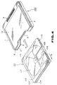
- Fig.4 shows a casing 100 for a disc cartridge 101 which includes a cartridge main body 102 and a recording disc, such as an optical disc or a magneto-optical disc, accommodated therein.
- a recording disc such as an optical disc or a magneto-optical disc
- the disc cartridge 101 includes the cartridge main body 102 made up of upper and lower halves 103, 104 abutted and connected to each other in the form of a thin case, as shown in Figs.4 and 5.
- the recording disc 117 is housed for rotation within the cartridge main body 102.
- the recording disc 117 includes a disc substrate formed of a synthetic resin and a signal recording layer deposited on one of the major surfaces of the disc substrate.
- the recording disc 117 has a centre chucking aperture 114.
- the rim part of the chucking aperture 114 on the major surface of the disc substrate serves as a chucking reference surface 116.
- a chucking plate 115 is mounted on the opposite major surface of the disc substrate for closing the chucking aperture 114.
- the cartridge main body 102 is formed as a thin case having a substantially rectangular major surface having a side having a length substantially corresponding to the diameter of the recording disc 117.
- a pair of substantially rectangular recording/reproducing apertures 106, 107 are formed in register with each other on the upper and lower major surfaces of the cartridge main body 102.
- the recording/reproducing aperture 107 in the lower half 104 causes one of the major surfaces of the recording disc 117 to be exposed to outside across the inner and outer rims of the disc 117.
- the recording/reproducing aperture 106 in the upper half 103 causes the other major surface of the recording disc 117 to be exposed to outside across the inner and outer rims of the disc 117.
- the recording/reproducing apertures 106, 107 are opened or closed by a shutter member 105 slidably mounted on the cartridge main body 102.
- the shutter member 105 is formed from a thin metal sheet by bending it into a substantially U-shape and includes a pair of shutter plates for opening and closing the recording/reproducing apertures 106, 107.
- the shutter plates are interconnected at a centre web portion and extended parallel to each other.
- the shutter member 105 has its centre web portion slidably supported by a lateral side of the cartridge main body 102 so that the shutter plates are extended parallel to the major surfaces of the cartridge main body 102.
- the shutter member 105 When the shutter member 105 is moved to a position in which the shutter plates are in register with the recording/reproducing apertures 106, 107, the shutter plates close these recording/reproducing apertures 106, 107. As shown by arrow B in Figs.4 and 5, the shutter member 105 is slid rearwards with respect to the direction of introducing the disc cartridge 101 into the recording/reproducing apparatus indicated by arrow A in Fig.4. The result is that the shutter member 105 has its shutter plates moved towards the rear on the major surface of the cartridge main body 102 to open the recording/reproducing apertures 106, 107.
- a circular chucking aperture 108 is formed at a centre position on the lower major surface of the cartridge main body 102.
- the chucking aperture 108 causes the chucking aperture 114, the chucking reference surface 16 and the chucking plate 115 of the recording disc 117 to be exposed to outside.
- the lower major surface of the cartridge main body 102 has a pair of positioning holes 112, 113 for positioning the disc cartridge when the disc cartridge is loaded in position on the recording/reproducing apparatus. These positioning holes 112, 113 are formed in the vicinity of the front and rear ends in the lower major surfaces of the cartridge main body 102.
- the lower major surface of the cartridge main body 102 is formed with a pair of recesses 110, 109 and a disc type discriminating recess 111.
- the recesses 110, 109 can be engaged by a disc loading unit of the recording /reproducing apparatus for capturing the disc cartridge by the disc loading unit.
- These recesses 110, 109 are formed on both lateral sides at the front side of the lower major surface of the cartridge main body 102 so as to be open on the lateral sides of the cartridge main body 102.
- the disc type discriminating recess 111 is formed on the front side in the lower major surface of the cartridge main body 102 so as to be open on the front side of the cartridge main body 102.
- the disc type discriminating recess 111 has its depth set depending on the type of the recording disc 117 housed in the cartridge main body.
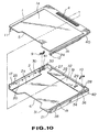
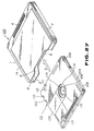
- the casing for the disc cartridge is made up of a top plate member 1 as a first member and a bottom plate member 2 as a second member, as shown in Figs.4 and 6 to 10.
- the top plate member 1 has a top plate section 1 a of a size and shape substantially corresponding to the size and shape of the major surface of the cartridge main body 102, and is integrally cast from e.g. a synthetic resin in the form of a flat plate.
- the top plate member 1 is formed of a light-transmitting material, such as acrylic resin, e.g. polymethacrylate, ABS resin, polycarbonate or polystyrene.
- the top plate member 1 has a pair of inner sidewall members 11, 12 on both lateral sides of the lower surface thereof extending parallel to the lateral sides of the top plate section 1 a , as shown in Fig.11.
- the top plate member 1 also has an inner rear wall member 15 parallel to the rear side of the top plate section 1 a , as shown in Fig.11.
- the inner sidewall members 11, 12 and the inner rear wall member 15 are cast as one with the top plate section 1 a for defining a U-shaped peripheral wall interrupted at the front side.
- These sidewall sections 11, 12 and the rear wall section 15 are of a height substantially equal to the thickness of the cartridge main body 102, and are inwardly offset from the lateral sides and the rear side of the top plate section 1 a by a distance corresponding to the thickness of the wall sections 11, 12 and 15.
- lateral engaging ribs 13, 14 On the outer lateral sides of the inner sidewall sections 11, 12 are formed lateral engaging ribs 13, 14 for extending laterally outwards, as shown in Figs.11, 12, 14 and 15. These engaging ribs 13, 14 are provided for extending from the vicinity of the front side towards the rear side and parallel to the lateral sides of the top plate section 1 a . These engaging ribs 13, 14 are positioned slightly above the lower ends of the inner lateral sidewall sections 11, 12, that is towards the top plate section 1 a .
- retention projections 23, 24 On the outer lateral sides of the inner sidewall sections 11, 12 are formed retention projections 23, 24 for being extended rearwards. These retention projections 23, 24 are provided towards the front side of the inner sidewall sections 11, 12 adjacent to the upper surfaces of the engaging ribs 13, 14. These retention projections 23, 24 are protruded by an amount slightly smaller than the amount of protrusion of the engaging ribs 13, 14. These retention projections 23, 24 each have a front end face at right angles to the sidewall sections 11, 12 and a rear end face inclined relative to the sidewall sections 11, 12 with the amount of protrusion being gradually decreased towards the rear side.
- slits 39, 40 are formed on the outer lateral sides of the inner sidewall sections 11, 12 on the outer lateral sides of the inner sidewall sections 11, 12 . These slits 39, 40 are formed to extend from the proximal ends towards the lower ends of the inner sidewall sections 11, 12.
- top plate section 1 a On the lower surface of the top plate section 1 a are formed a pair of lateral shoulders 48, 49 and a rear shoulder 50 on both lateral sides and on the rear side, respectively. These shoulders 48 to 50 protrude only slightly to prevent the disc cartridge 101 introduced into the casing 100 from being slidingly contacted with the mid portion of the top plate section 1 a .
- a cut-out 5 is formed on the front side of the top plate section 1 a for causing the rear end of the disc cartridge 101 housed within the casing 100 to be exposed to outside.
- the bottom plate member 2 has a bottom plate section 2 a of substantially the same shape as the top plate section 1 a and is cast as one from plastics or the like material.
- the bottom plate member 2 is formed of a material showing excellent heat resistance, such as heat-resistant ABS resin or polycarbonate.
- the bottom plate member 2 has a pair of outer sidewall members 17, 18 on both lateral sides of the upper surface thereof extending parallel to the lateral sides of the bottom plate section 2 a , as shown in Fig.10.
- the bottom plate member 1 also has an outer rear wall member 19 parallel to the rear side of the bottom plate section 2 a .
- the outer sidewall members 11, 12 and the outer rear wall member 19 are cast as one with the bottom plate section 2 a for defining a U-shaped peripheral wall interrupted at the front side.
- These outer sidewall sections 17, 18 and the rear wall section 19 are of a height substantially equal to the thickness of the cartridge main body 102, and are formed for extending along the lateral sides and the rear side of the bottom plate section 2 a .
- lateral grooves 20, 21 for extending inwards, as shown in Figs.13, 16 and 17.
- These grooves 20, 21 are formed parallel to the upper surface of he bottom plate section 2 a from the vicinity of the front sides towards the rear sided of the outer sidewall members 17, 18.
- These grooves 20, 21 are formed slightly above the proximal sides of the outer sidewall sections 17, 18, that is at slightly spaced apart positions with respect to the bottom plate section 2 a , with the upper ends of the grooves 20, 21 serving as engaging lugs.
- a flange 22 operating as a rear engaging lug is formed for being protruded towards the front side.
- the flange 22 is provided for being extended from one towards the other lateral sides of the outer rear wall member 19 along the upper edge of the outer rear wall member 19 in parallel with the upper surface of the bottom plate section 2 a .
- the lower lateral side of the flange 22 and the bottom plate section 2 a make up an engaging rear groove.
- retention recesses 25, 26, are formed in register with the retention projections 23, 24 at forward sides of the outer sidewall members 17, 18 in communication with the upper sides of the engaging lateral grooves 20, 21.
- These retention recesses 25, 26 are each slightly shallower in depth than the engaging lateral grooves 20, 21.
- recesses 37, 38 for extending as steps across the front and rear sides of the outer sidewall sections 17, 18 along the upper lateral edges of the sidewall members 17, 18.
- the upper sides of the recesses 37, 38 are opened towards the upper lateral sides of the outer sidewall members 17, 18.
- the rear portions of the outer sidewall members 17, 18 are formed with a pair of cut-outs 41, 42 in register with the vertical slits 39, 40. These cut-outs 41, 42 are formed for extending from the upper ends towards the proximal sides of the outer sidewall sections 17, 18.
- the front side of the bottom plate section 2 a is formed with a cut-out 6 for causing a rear part of the disc cartridge 101 housed within the casing 100 to be exposed to outside.
- a pair of lateral steps 30, 31 and a rear step 32 are formed on the lateral sides and the rear side of the bottom plate 2 a. These steps 30 to 32, having a small amount of protrusion, are used for preventing the disc cartridge 101 from being slidingly contacted with the mid portion of the bottom plate section 2 a when the disc cartridge 101 is introduced into the casing 100.
- the rear step 32 is formed with a mistaken insertion inhibiting protrusion 29.
- This protrusion is formed at a position on the rear side of the bottom plate section 2 a slightly offset from the centre towards a lateral side of the bottom plate section 2 a .
- the function of the mistaken insertion inhibiting protrusion 29 will be explained subsequently.
- a pair of rib-shaped reinforcements 27, 28 in continuation to the flange 22, as shown in Figs.16 and 18.
- These reinforcements 27, 28 are cast as one with the inner surface of the outer rear wall member 19 for extending from the flange 22 up to the bottom plate section 2 a .
- At the lower parts within the engaging lateral grooves 20, 21 are formed plural reinforcement ribs 43 for extending from the lateral sides of the grooves 20, 21 up to the bottom plate section 2 a .
- the reinforcements 27, 28, shown in Fig.18 may be formed as shown at a in Fig.19.
- the reinforcement 28a shown in Fig.19 is formed on the entire surface of the flange 22 of the outer rear wall member 19 and on both sides of the engaging rear groove.
- the top plate member 1 and the bottom plate member 2 are provided with step-shaped protrusions which are spaced apart from the sidewall members, as shown in Fig.22.
- These protrusions 59, 60 are formed as ribs as one with the upper surface of the bottom plate member 2 in parallel with the outer sidewall sections 17, 18.
- the top plate member 1 and the bottom plate member 2 are connected to each other by having the lateral engaging ribs 13, 14 engaged in the engaging lateral grooves 20, 21, as shown in Fig.20, and by having the rear engaging rib 16 engaged between the flange 22 and the bottom plate section 2 a , that is in the engaging rear groove.
- the top plate member 1 is positioned ahead of the bottom plate member 2 and the rear sides of the lateral engaging ribs 13, 14 are introduced at the front ends of the engaging lateral grooves 20, 21, with the top plate member 1 being then moved towards rear for sliding the lateral engaging ribs 13, 14 within the engaging lateral grooves 20, 21.
- the rear engaging rib 16 is engaged in the rear engaging groove, while the retention projections 23, 24 are engaged with the retention recesses 25, 26.
- these retention projections 23, 24 are first introduced into a space between the sidewall members 17, 18, from the front ends of the outer sidewall members 17, 18 for outwardly thrusting and thereby slightly deflecting the outer sidewall members 17, 18.
- the outer sidewall members 17, 18 are restored to their initial states for engaging the retention projections 23, 24 in the retention recesses 25, 26.
- the top plate member 1 and the bottom plate member 2 are engaged with each other at the lateral sides and rear sides of the top plate section 1 a and the bottom plate section 2 a , with the top plate section 1 a and the bottom plate section 2 a extending parallel to each other, for defining an opening at the front side.
- This opening has a length substantially corresponding to the length of a side of the cartridge main body 103, and a width substantially corresponding to the thickness of the cartridge main body 102.
- the lower ends of the inner sidewall members 11, 12 and the inner rear wall member 15 are caused to bear against the upper surface of the bottom plate section 2 a , while the upper ends of the outer sidewall members 17, 18 and the outer rear wall member 19 are caused to bear against the rim of the lower surface of the top plate section 1 a .
- the recesses 37, 38 formed on the upper sides of the outer sidewall members 17, 18 and both lateral sides of the top plate section 1 a delimit lateral grooves 7,8. That is, the upper ends of the outer sidewall members 17, 18 are engaged with the lateral sides of the top plate section 1 a at the positions offset inwards by a distance equal to the depths of the recesses 37, 38, as shown in Fig.20.
- These lateral grooves 7, 8 are formed for being extended from the front side towards the rear side of the lateral surface of the casing 100.
- the rear bottom ends of the lateral grooves 7, 8 are formed with bottomed holes constituted by slits 41, 42 formed in the outer sidewall members 17, 18 and by the vertical grooves 39, 40 formed in the inner sidewall members 11, 12.
- an injection gate of a metal mould for injection moulding the top plate member 1 is formed as a so-called pin gate at a position sightly offset towards the rear on the upper surface of the top plate section 1 a , as shown at G1 in Fig.15.
- An injection gate of a metal mould for injection moulding the bottom plate member 2 is formed as a so-called pin gate at a position sightly offset towards the rear on the lower surface of the bottom plate section 2 a , as shown at G2 in Fig.16. That is, the top plate member 1 and the bottom plate member 2 are similar to each other in shape and the gate positions are in register with each other.
- the top plate member 1 and the bottom plate member 2 are substantially similar in the state of deformation, such as shrinkage, caused by the cooling step during injection moulding, so that the engaging ribs of the sidewall sections may be engaged smoothly with each other.
- the injection gate may also be so-called film gates or submarine gates, instead of the pin gates.
- the injection gates on the top plate member 1 and on the bottom plate member 2 may be positioned in register with each other to provide for a substantially equal state of deformation, such as shrinkage, to ensure smooth engagement of the top and bottom plate members 1 and 2.
- a pair of locking members 9, 10 are provided for retaining the disc cartridge 101 introduced between these members 1 and 2.
- These locking members 9, 10, formed of a flexible and resilient material, such as polyacetal, are composed of end grips 44, 45 and a resilient arm 46 spanning the end grips 44, 45, as shown in Figs.23 to 26.
- the end grips 44, 45 are columnar-shaped and have their axes parallel to each other.
- the resilient arm 46 is arcuate in shape and interconnect the end grips 44, 45.
- the resilient arm 46 is bent in a direction at right angles to the axes of the grips 44, 45.
- the apex point of the arcuately bent arm 46 is at an equidistant position with respect to the grips 44, 45.
- the arcuately bent parts of the locking members 9, 10 play the part of retention surfaces 47 for retaining the disc cartridge 101.
- the locking members 9, 10 are mounted by a pair of locking member mounting sections 33, 34 formed on the bottom plate member 2.
- These locking member mounting members 33, 34 are formed on the inner lateral surfaces of the outer sidewall sections 17, 18 at the recessed inner ends of the sidewall members 17, 18, as shown in Fig.16.
- These mounting member 33, 34 are each provided with fore and aft holding protrusions 54, 55.
- These holding protrusions 54, 55 are formed at the lower parts of the outer sidewall members 17, 18 for being protruded inwards in continuation to the bottom wall section 2 a . That is, these holding projections 54, 55 are provided at the corners between the outer sidewall sections 17, 18 and the bottom plate section 2 a .
- These holding protrusions 54, 55 are mounted facing each other at a distance substantially corresponding to the lengths of the locking members 9, 10.
- the facing sides of the holding protrusions 54, 55 are formed with holding recesses 52, 53, respectively.
- These holding recesses 52, 53 are opened towards the top and are each of a cross-sectional profile of a part of an ellipse or an oblong circle having its longer axis oriented in the fore-and-aft direction.
- the locking members 9, 10 are held by the holding projections 54, 55 by having the grips 44, 45 fitted into the holding recesses 52, 53.
- These locking members 9, 10 are mounted with the axes of the grips 44, 45 at right angles to the bottom plate section 2 a and with the retention surfaces 47 directed towards the inner side of the bottom plate section 2 a . That is, the arcuately bent arms 46 of the locking members 9, 10 are adapted for being protruded towards the inner side of the bottom plate section 2 a .
- the arcuately bent arms 46 of these locking members 9, 10 may be resiliently bent in a direction of approaching the outer sidewall members 17, 18. When the arms 46 are resiliently deflected in this manner, the grips 44, 45 are moved in the fore-and-aft direction within the holding recesses 52, 53, respectively.
- the inner sidewall sections 11, 12 of the top plate member 1 are cut out at the rear parts so that the rear parts are shorter in a distance of depending from the top plate section 1 a than the central and forward parts by a length corresponding to the width of the locking members 9 and 10. This prevents the inner sidewall sections 11, 12 from being abutted against the locking members 9, 10 held by the locking member holding parts 33, 34, while preventing the locking members 9, 10 from being detached upwards from the locking member holding parts 33, 34.
- the back sides of the locking member mounting parts 33, 34 that is the rear parts of the outer lateral sides of the outer sidewall members 17, 18, are subject to so-called sink during integral injection moulding of the bottom plate member 2.
- sink is produced because the portions of the outer sidewall members 17, 18 provided with the locking member mounting parts 33, 34 are increased in thickness as compared to other parts of the outer sidewall members 17, 18 and hence are receded inwards in the course of cooling during the moulding process.
- the portions of the outer sidewall members 17, 18 in register with the locking member mounting parts 33, 34 are hollow due to the provision of clearances 35, 36.
- the disc cartridge 1021 is introduced into the space between the top plate member 1 a and the bottom plate member 2 a from the front side via the opening in a direction shown by arrow A in Fig.4.
- the lateral surfaces of the front side of the cartridge main body 102 thrust the retention surfaces 47, 48 of the locking members 9, 10 for deflecting the arms 46, 46 in a direction of approaching the outer sidewall members 17, 18.
- the front side of the cartridge main body 102 reaches a predetermined position of being substantially abutted on the inner lateral wall 15 of the casing 100
- the locking members 9, 10 are in register with the recesses 110, 109.
- the arms 46, 46 of the locking members 9, 10 are restored to their initial states under their own resiliency for causing the retention surfaces 47, 47 to be engaged in the recesses 110, 109.
- the retention surfaces 47, 47 of the locking members 9, 10 engaging in the recesses 110, 109, the disc cartridge 101 is retained and limited in its movement of being detached rearwards, that is out of the casing 100 via the opening under shock or vibrations.
- the mistaken insertion inhibiting protrusion 29 is fitted at this time in the disc discriminating recess 111 of the disc cartridge 101, as shown in Fig.31.
- the disc cartridge 101 which is now in position within the casing 100, is accommodated between and protected from outside by the members 1 and 2.
- casings 100 When a plurality of casings 100 are inserted into a rack adapted for containing plural casings, they are held in position by the lateral grooves 7, 8.
- the casings 100 may be protected against accidental removal from the rack by engaging means provided on the rack being engaged in the bottomed openings formed by the slits 41, 42.
- the rear part of the disc cartridge 101 exposed to outside via the cut-outs 5, 6 is held by the finger and pulled rearwards with respect to the casing 100.
- This causes the retention surfaces 47, 47 of the locking members 9, 10 to be thrust by the forward lateral sides of the cartridge main body 102, while causing the arms 46, 46 of the locking members 9, 10 to be deflected in a direction of approaching the outer sidewall members 17. 18 for releasing the retention of the disc cartridge 101.
- the disc cartridge 101 may now be taken out of the casing 100 via the opening.
- the locking members 9, 10 are reset to their initial states.
- the disc cartridge 101 may be moved further rearwards so as to be taken out of the casing 100.
- the casing 100 is designed to prevent the disc cartridge 101 from being introduced up to the housing complete position within the casing 100 even when the disc cartridge 101 is inserted via the opening in the mistaken direction.
- the locking members 9, 10 are not faced by the recesses 110, 109, so that the locking members 9, 10 remain thrust and resiliently deflected by the cartridge main body 102, as shown in Fig.33. If the locking members 9, 10 are left for extended period of time in the resiliently deflected state, the locking members 9, 10 undergo plastic deformation so that the disc cartridge 1001 inserted in the regular position cannot be held by the locking members 9, 10.
- the mistaken insertion inhibiting protrusion 29 is caused to bear against the cartridge main body 102 to inhibit the insertion thereof into the casing 100, as shown in Fig.32. That is, the distance from the upper end face of the mistaken insertion inhibiting protrusion 29 up to the lower surface of the top plate section 1 a , as indicated by arrow L in Fig.32, is shorter than the thickness of the cartridge main body 102 as indicated by arrow T in Fig.2. Consequently, the disc type discriminating recess 111 is not faced by the mistaken insertion inhibiting protrusion 29.
- the protrusion 29 If the protrusion 29 is not engaged with the recess 111, the protrusion 29 is caused to bear against the cartridge main body 102 to inhibit insertion of the disc cartridge 101 into the casing 100. Meanwhile, the protrusion 29 has a height lower than the depth of the disc type discriminating recess 111.
- the casing 100 which has accommodated the disc cartridge 101 therein as described above is packaged with an overlap film 201 by a packaging method as shown in Figs.34 to 41.
- the overlap film 201 is a thermally contractible film which is contracted on being heated and which is melted on being heated further.
- a label member of paper 204 which is to be a sheet-shaped member, is applied over the front end of the casing 100 so as to cover up the cut-outs 5 and 6.
- the label member 203 is bent at its mid part into U-shape and applied to the casing 100 to cover up the top plate section 1 a and the bottom plate section 2 a of the casing 100.
- the two parallel bent portions of the label member 204 are located at substantially the mid positions of the label member 204 and are spaced apart from each other by a distance corresponding to the thickness of the casing 100. With the label member 204 applied over the casing 100, the latter presents a planar outer lateral surfaces.
- the label member 204 is used as a so-called index label.
- the label member 204, used as index label is made up of a label coated with an adhesive and a release paper to which the label is bonded.
- the wrapping is what is termed a caramel wrapping.
- the casing 100 is introduced into the inside of an overlap film 201 obtained by interconnecting two opposing edges of two film halves. Both end parts of the overlap film 201 in the tubular form are bent inwards to form superposed sections 202, 203, as shown in Fig.37. These superposed sections 202, 203 are heated and fused together by heat welding by a pair of heating ironing members 301, 302 making up a wrapping unit. These superposed sections 202, 203 are formed on the outer lateral surfaces of the lateral members of the casing 100.
- the heating ironing members 301, 302 are formed of metal and mounted in opposition to each other. These ironing members 301, 302 are heated to a predetermined temperature and moved relative to each other to change the distance therebetween. These ironing members 301, 302 are provided with recesses 303, 304 in the opposite lateral sides, respectively. These recesses 303, 304 are contoured to conform to the profile of the lateral surfaces of the casing 100 so that both lateral sides of the casing 100 may be introduced up to the bottom of the recesses. Since the ridges of the lateral surfaces of the casing 100 are rounded, both corners of the recesses 303, 304 are also rounded to present a cylindrical shape.
- the recesses 303, 304 are profiled to permit the ridges of the casing 100 to be inserted therein. The result is that, if the overlap film 201 is shifted in one or the other direction so that the overlap film 201 has its one end extending over the entire lateral surface of the casing 100 to reach the opposite side, that is the top late section 1 a or the bottom plate section 2 a , the extended portion of the overlap film may still be heated by the ironing members 301, 302 so as to be heat welded, as shown in Figs.35 and 36.
- the overlap film 201 is heated and shrunk so as to be tightly applied to the outer surface of the casing 100 to complete the wrapping, as shown in Fig.41. Since the casing 100 presents a planar outer surface, the overlap film 201 may be tightly applied to the outer lateral surface of the casing 100 on which the label member 204 is applied previously.
- the superposed portions 202, 203 of the overlap film 201 are applied to cover up the lateral grooves 7, 8, as shown in Fig.34.
- the portions of the superposed parts 202, 203 lying over the lateral grooves 7, 8 are not thrust fully by the ironing members 301, 302 so that there is a risk that these portions will not be fused together.
- the overlap film 201 is partially positioned towards one or the other sides of the casing 100, as shown in Figs.35 and 36.
- one of the superposed parts 202, 203 becomes narrower in width than the lateral grooves 7, 8, as indicated by arrow R in Figs.35, 36.
- the superposed portions 202, 203 are not positioned over the lateral grooves 7, 8, so that the superposed portions 202, 203 are fused together reliably.
- the sheet-shaped member employed in the packaging method may also be a label member 205 which will cover only the front side of the casing 100, as shown in fig.2, instead of covering both the top plate section 1 a and the bottom plate section 2 a , as described above.
- the label member 205 has two parallel folding lines and is bent into U-shape. The folded portion is offset towards one lateral side from the centre of the label member 205 and both the flaps are spaced part from each other by a distance corresponding to the thickness of the casing 100.
- the casing 100 presents a planar outer surface when it is sheathed by the label member 205.
- the locking members 9, 10 are mounted on a pair of locking member mounting parts 33, 34 formed on the bottom plate member 2. These locking member mounting parts 33, 34 are formed on the rear parts of the opposing inner lateral sides of the outer sidewall members 17, 18, as shown in Fig.16. These locking member mounting parts 33, 34 are provided with front and rear holding protrusions 54, 55, as shown in Figs.43 and 44. These holding protrusions 54, 55 are formed at the lower parts of the outer sidewall members 17, 18 for being protruded inwards in continuation to the bottom wall section 2 a . That is, these holding projections 54, 55 are provided at the corners between the outer sidewall sections 17, 18 and the bottom plate section 2 a .
- These holding protrusions 54, 55 are mounted facing each other at a distance substantially corresponding to the lengths of the locking members 9, 10.
- the facing sides of the holding protrusions 54, 55 are formed with holding recesses 52, 53, respectively.
- These holding recesses 52, 53 each have a substantially cylindrical inner surface and are opened towards the top with a cross-sectional profile of a part of an ellipse or an oblong circle having its longer axis oriented in the fore-and-aft direction.
- the difference between the longer axis and the shorter axis of an ellipse of the cross- sectional profile of reach of the holding recesses 52, 52 is about e.g. 0.3 mm, if the grips 44, 45 are of a diameter of about 1.2 mm.
- the locking members 9, 10 are held by the holding projections 54, 55 by having the end grips 44, 45 fitted into the holding recesses 52, 53. These locking members 9, 10 are positioned with the axes of the grips 44, 45 at right angles to the bottom plate section 2 a and with the retention surfaces 47 directed towards the bottom plate section 2 a . That is, the arcuately bent arms 46 of these locking members 9, 10 can for be extended towards the inner side of the bottom plate section 2 a .
- these locking members 9, 10 are designed for being resiliently deflected in a direction of approaching the outer sidewall members 17, 18 as indicated by arrow in Fig.46.
- bent arms 46 are deflected resiliently in this manner, the end grips 44, 45 are moved in the fore-and-aft direction within the holding recesses 52, 53.
- An abutment boss 58 is provided on the opposite side of the retention surface 47 of each of the locking members 9, 10.
- the abutment boss 58 When the arm 46 is resiliently deflected in a direction towards the outer sidewall members 17, 18, the abutment boss 58 is abutted against the apex of an abutment rib 57 provided at a mid part of each of the locking member mounting parts 33, 34, for preventing excessive resilient deflection of the arm 46 as shown in Fig.46.
- the rib 57 is formed for extending vertically between holding protrusions 54, 55 on the inner surface of each of the outer sidewall members 17, 18.
- the inner sidewall members 11, 12 of the top plate member 1 are cut out at the rear ends so that the sidewall members 11, 12 depend from the top plate section 1 a at the cut-out parts a shorter distance than at the mid and front parts so as to leave a void equal to the width of each of the locking members 9, 19. That is, the inner sidewall members 11, 12 clear the locking members 9, 10 held by the locking member holding parts 33, 34 while preventing these locking members 9, 10 from being detached upwards from the locking member holding parts 33, 34.
- the retention members in the casing 100 for the disc cartridge may also be locking members 9, 10 shown in Fig.44 in which the mid part of the bent arm 46 is flattened at 56, in place of the locking members 9, 10 shown in the preceding embodiment.
- This second modification of the casing for the disc cartridge is hereinafter explained.
- the mid parts of these locking members 9, 10 are designed as retention means for being engaged in recesses 110, 109.
- the locking members 9, 10 are thrust by front lateral surfaces of the cartridge main body 102 for resiliently deflecting the bent arms 46.
- the bent arms 46 are restored to their initial states for engaging the retention means in the recesses 110, 109.
- the locking members 9, 10, having the retention parts engaged in the recesses 109, 110, prevent the disc cartridge 101 from being disengaged from the casing 100 under sock or vibrations.
- the retention members of the casing 100 may also be designed as locking parts 60 formed as one with the bottom plate member 2, instead of as the locking members 9, 10 formed distinctly from the bottom plate member 2 shown in the preceding embodiments. This third modification of the casing for the disc cartridge is hereinafter explained.
- These locking parts 60 are paired and formed at the inner rear surfaces of the outer sidewall members 17, 18 for facing each other.
- the locking parts 60 are formed at the lower portions of outer sidewall members 17, 18 as substantially plate- shaped members extended in the fore-and-aft direction.
- These locking parts 60, 60 have their front sides formed as one with the outer sidewall members 17, 18, with their rear ends being free ends.
- the locking parts 60 may be resiliently deflected in a direction towards the outer sidewall members 17 ,18, with the front ends as fulcrum points, as indicated by arrow D in Fig.48.
- the inner surfaces of the outer sidewall members 17, 18 are formed with clearances in register with the locking parts 60 to permit resilient deflection of these locking parts 60.
- the mid portions of these locking parts 60 are bent in a substantially trapezoidal shape directed towards the inside of the bottom plate section 2 a .
- the mid portions of the locking parts 60 are formed as retention means engaged in the recesses 110, 109.
- the retention means of the locking part 60 has a front inclined surface 62 facing the inserting direction of the disc cartridge 101, shown by arrow C in Fig.48, which is sloped at a more moderate tilt than the opposite rear inclined surface in order to permit the locking parts 60 to be resiliently deflected more readily when introducing or taking out the disc cartridge 101 into or from the casing 100.
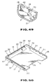
- a locking boss 70 which is to be a retention boss, as shown in Figs.49 and 50.
- the locking boss 70 is formed as one with the bottom plate member 2.
- the locking boss 70 is provided at a rear portion of the outer sidewall member 18.
- the locking boss 70 is substantially semicylindrical-shaped and has its planar end face extending substantially parallel to the bottom plate section 2 a and its semi-arcuate portion extending inwards from the lateral surface of the outer sidewall member 18.
- the inner sidewall members 11, 12 of the top plate member 1 are cut out at the rear ends so that the sidewall members 11, 12 depend from the top plate section 1 a at the cut-out parts a shorter distance than at the mid and front parts so as to leave a void equal to the width of the locking member 9 and a void equal to the height of the locking boss 70, as shown in Fig.53. That is, the inner sidewall members 11, 12 clear the locking member 9 held by the locking member holding part 33 and the locking boss 70 while preventing these locking member 9 from being detached upwards from the locking member holding part 33.
- the disc cartridge 101 is introduced via the opening in the casing 100 from the front side, as shown by arrow A in Fig.4, into a space between the top plate section 1 a and the bottom plate section 2 a .
- the forward end of the lateral surface of the cartridge main body 102 facing the locking member 9 thrusts the retention surface 47 of the locking member 9 for deflecting the arm 46 towards the outer sidewall member 17.
- the forward end of the opposite lateral surface of the cartridge main body 102 is caused to bear against the peripheral surface of the locking boss 70 so as to be shifted slightly towards the locking member 9.
- the arm 46 of the locking member 9 is restored at this time to its initial state under its own resiliency, with the retention surface 47 being intruded into recess 109, as shown in Fig.52.
- the locking member 9 thrusts the cartridge main body 102 towards the opposite side for introducing the locking boss 70 into the opposite side recess 110.
- the distance between the apex of the retention surface 47 and that of the peripheral surface of the locking boss 70, indicated by arrow Lc in Fig.52, is selected to be smaller than the width of the cartridge main body 102, shown by arrow W in Fig.52. Consequently, with the retention surface 47 of the locking member 9 and the locking boss 70 introduced into the recesses 109, 110, the cartridge main body 102 is retained by being clamped from both lateral sides and thereby prevented from being disengaged via the opening of the casing 100 towards outside under shock or vibrations.
- the mistaken insertion inhibiting protrusion 29 is engaged at this time in the disc type discriminating recess 111 of the disc cartridge 101.
- the disc cartridge 101 thus accommodated in position within the casing 100, is contained between and protected by the plate members 1 and 2.
- the rear parts of the disc cartridge exposed to outside via cut-outs 5, 6 are pulled rearwards with respect to the casing 100.
- the locking member 9 then has its retention surface 47 thrust by the front part of the lateral surface of the cartridge main body 102 so that the arm 46 is flexed towards the outer sidewall member 17 to release retention of the cartridge main body 102.
- the disc cartridge 101 may be taken out of the casing 100 via the opening. If the disc cartridge 101 is moved further rearwards, the locking member 9 is reset to its initial state.
- the disc cartridge 101 may be taken out of the casing 100 by pulling the disc cartridge outwards.
- the casing 100 for the disc cartridge may also be provided with a pair of locking bosses 71, 71, as retention bosses, on both inner lateral surfaces of the main casing member, in place of the locking member 9 and the locking boss 70.
- These locking bosses 71, 71 are formed at rear parts of the outer sidewall members 17, 18 in opposition to each other.
- the locking bosses are formed as one with the outer sidewall members and with the bottom plate section 2 a .
- These locking bosses 71, 71 are substantially semicylindrical-shaped and have their flat end faces parallel to the outer sidewall members 17, 18 while having the semi-arcuate peripheral surfaces extending upwards from the bottom plate section 2 a , as shown in Fig.57.
- the present casing 100 is not provided with the flange 22 providing the rear engaging rib 16 and the rear engaging groove, with the outer lateral surface of the inner rear wall member 15 and the inner peripheral surface of the outer rear wall member 19 being planar, as shown in Figs.53 and 54. That is, with the lateral sidewall sections of the top plate member 1 and the bottom plate member 2 in engagement with each other, the rear wall members 15, 19 are caused to bear against each other and yet are movable vertically relative to each other.
- the sidewall sections 11, 12, 17, 18 are engaged at an area L1 except a rear part L2 as shown in Fig.56. That is, with the present casing 100 for the disc cartridge, the rear parts of the top plate member and the bottom plate member are resiliently flexed in a direction away from each other.
- the rear wall members 15, 19 may also be engaged with each other at a central area L4 excluding both lateral side area L3 in Fig.56, in which case both lateral side areas of the top and bottom plate members may be resiliently flexed at the rear end portions n a direction away from each other.
- both front lateral sides of the bottom plate section of the cartridge main body 102 thrust the upper surface of the locking bosses 71, 71 for deflecting the bottom plate section 2 a downwards, that is away from the top plate section 1 a .
- the rear parts of the lateral grooves 7, 8 are widened from the initial state, as indicated by arrow C in Fig.59.
- the distance between end faces of the locking bosses 71, 71 indicated by arrow Lc in Fig.59, is selected to be smaller than the width of the cartridge main body 102 indicated by arrow W in Fig.52. Consequently, by having the locking bosses 71, 71 introduced into the recesses 109, 110, the cartridge main body 102 is retained by being clamped from both lateral sides and thereby prevented from being disengaged via the opening of the casing 100 towards outside under shock or vibrations.
- the disc cartridge 101 thus accommodated in position within the casing 100, is contained between and protected by the plate members 1 and 2.
- the rear parts of the disc cartridge exposed to outside via cut- outs 5, 6 are pulled rearwards with respect to the casing 100.
- the locking member 9 then has its locking bosses 71, 71 thrust by the front part of the lateral surfaces of the cartridge main body 102 so that the rear part of the bottom plate section 2 a is deflected in a direction away from the top plate section 1 a to release retention of the cartridge main body 102 by the locking bosses 71, 71.
- the disc cartridge 101 may be taken out of the casing 100 via the opening. If the disc cartridge 101 is moved further rearwards, the locking member 9 is reset to its initial state. The disc cartridge 101 may be taken out of the casing 100 by pulling the disc cartridge outwards.
- these locking bosses may be substantially triangular-shaped with the triangular end faces extending parallel to the outer sidewall members 17, 18 and with upper ridges defined by inclined surfaces being protruded upwards away from the bottom plate section 2 a .
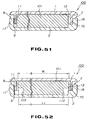
- a pair of recesses 80, 81 defining bottomed holes.
- These recesses 80, 81 are formed as grooves extended vertically from the proximal sides up to the lower ends of the inner sidewall members 11, 12, that is from the lower surface of the top plate section 1 a up to the vicinity of the lower ends of the inner sidewall members 11, 12, as shown in Fig.61.
- a pair of slits 82, 83 for defining a bottomed hole in register with the recesses 80, 81.
- These slits 82, 83 are formed in a direction from the upper ends towards the proximal ends of the outer sidewall members 17, 18, as shown in Fig.63.
- recesses 37, 38 formed on the upper ends of the outer lateral surfaces of the outer sidewall members 17, 18 and the vicinity of the lateral sides of the top plate section 1 a define the above-mentioned lateral grooves 7, 8. That is, the upper sides of the outer sidewall members 17, 18 are caused to bear against the lateral sides of the top plate section 1 a at positions offset inwards by a distance equal to the depth of the recesses 37, 38 as shown in Fig.20.
- These lateral grooves 7, 8 are formed for extending from the front sides up to the rear ends of the lateral surfaces of the casing 100.
- bottomed holes play the role of retaining the casing 100 by having engaging members of the rack engaged therein.
- These bottomed holes are of a depth sufficient to permit the engaging members to be engaged therein.
- the depth of the bottomed holes indicated by arrow G in Fig.63, corresponds to the depth of the recesses 80, 81 and the thickness of the outer sidewall members 17, 18 summed together, as shown in Fig.63. Such depth is deeper than the thickness of the outer sidewall members 17, 18 or the thickness of the inner sidewall members 11, 12.
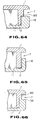
- the lateral grooves 7, 8 are not limited to those defined by the top plate 1 a and the recesses 37, 38, as in the preceding embodiment, but may be defined by the upper end faces of the outer sidewall members 17, 18, outer lateral surfaces of the inner sidewall members 11, 12 and by the vicinity of the ends of the top plate section 1 a , in which case the inner sidewall members 11, 12 have the lower ends abutted against the bottom plate section 2 a and are provided on their outer sides with step-shaped abutments 85, as shown in Fig.64.
- the outer sidewall members 17, 18 are free of the recesses 37, 38 but are formed as planar upper end faces.
- the outer sidewall members 17, 18 have the upper lateral end portions abutted against the lower surfaces of the abutments 85, while being abutted against the outer lateral surfaces of the inner side wall members 11, 12 by their inner lateral surfaces.
- the inner sidewall members 11, 12 may also be free of the abutments 85, as shown in Fig.65. In such case, the outer sidewall members 17, 18 are caused to bear and support the lower end portions of the outer lateral surfaces of the inner sidewall members 11, 12.
- the lateral grooves 7, 8 may also be defined by the recesses 37, 38 formed on the upper ends of the outer sidewall members 17, 18, the outer lateral surfaces of the inner sidewall members 11, 12 and the vicinity of the end parts of the top plate section 1 a , as shown in Fig.66.
- the inner sidewall sections 11, 12 have their ends abutted against the bottom plate section 2 a and are provided on their outer sides with step-shaped abutments 86.
- the outer sidewall members 17, 18 are formed with the recesses 37, 38. These outer sidewall members 17, 18 have their upper ends, that is the portions thereof offset more inwardly than the recesses 37, 38, abutted against the lower surfaces of the abutments 86.
- the outer sidewall members are abutted against and support the outer lateral surfaces of the inner sidewall sections 11, 12 by their inner lateral surfaces.
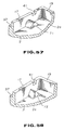
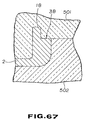
- moulding may be achieved by a metal mould of a simplified structure which is made up only of an upper mould 501 and a lower mould 502 and which is not provided with a slide core, as shown in Fig.67.
Landscapes
- Engineering & Computer Science (AREA)
- Mechanical Engineering (AREA)
- Manufacturing & Machinery (AREA)
- Packaging For Recording Disks (AREA)
- Packaging Of Annular Or Rod-Shaped Articles, Wearing Apparel, Cassettes, Or The Like (AREA)
- Packages (AREA)
- Auxiliary Devices For And Details Of Packaging Control (AREA)
- Containers And Plastic Fillers For Packaging (AREA)
- Catching Or Destruction (AREA)
Abstract
Description
- The invention relates to a disc cartridge casing to package a disc cartridge comprising a recording disc, such as an optical disc or a magneto-optical disc, contained in a main cartridge body.
- A so-called sleeve casing has been proposed as a casing for packaging a disc cartridge comprising a recording disc and a cartridge main body housing the disc or a tape cassette comprising a tape reel holding a recording tape and a cassette housing the tape reel therein. Such a
sleeve casing 401 is shown in Figures 1 to 3 of the accompanying drawings and is formed by a sheet-shaped member of a synthetic material, such as polypropylene (PP) or polyethylene terephthalate (PFT), bent into a box one side of which is open at 404 to provide a pouch-shaped structure, as shown in Fig.1. Acassette 405 as above-mentioned, having a recording medium housed therein, can be introduced via the opening 404 and held within thesleeve casing 401. In general, thesleeve casing 401 is of a size just large enough to accommodate thecassette 405 having the recording medium therein to hold the cassette by the force of friction between the outer surface of the cassette and the inner surface of the sleeve casing. Thesleeve casing 401 has cut-outs sleeve casing 401. - Since the sleeve casing is formed by bending a sheet-shaped member formed of paper or synthetic resin, it cannot be increased in thickness beyond a certain limit in order to retain its foldability, thus rendering it difficult to develop a sufficient toughness.
- If the sleeve casing is used as a casing for holding a
disc cartridge 405, problems arise if the casing for holding the disc cartridge therein is not of a sufficient toughness since the disc cartridge cannot then be protected reliably. That is, if an external pressure is applied to the casing with the disc cartridge contained therein, the casing tends to be deformed easily. The result is the possible destruction or deformation of the disc cartridge contained in the casing under an external pressure. Also if many disc cartridges contained in respective casings are stacked one upon the other, the casings tend to be deformed under the weight of the overlying disc cartridges. The result is again the possible destruction or deformation of the disc cartridges. - Conventional sleeve casings for disc cartridges are not provided with means for retaining the disc cartridges contained therein. Consequently, the disc cartridge tend to be disengaged out of the casings under shock or vibrations. If a disc cartridge is disengaged out of a casing while it is transported while being contained therein, there is a risk that the disc cartridge will fall on the floor or ground to be destroyed under the resulting shock.
- Since the sleeve casing is formed by bending a sheet-shaped material, the opening through which the cartridge main body is introduced into or taken out of the casing cannot be formed with ease to a predetermined shape in the casing. As the opening in the casing can be deformed, difficulties tend to be incurred in the operation of introducing a disc cartridge into the casing.
- As a solution to such problems, it may be contemplated to form a casing of two casing halves, that is a top plate member and a bottom plate member, in a similar construction to the two halves of a cartridge main body, the two plate members being abutted and connected to each other to form a casing. The members can be cast integrally by injection moulding without the necessity of performing a bending or folding operation. The result is that these plate members cannot be formed of a sufficiently tough material.
- However, if the two plate members of the casing are connected together by set screws, the two plate members become complicated in structure. Besides, since screw receiving sockets need to be so provided as to clear the disc cartridge, the top and bottom plate members become bulky in size as compared to the disc cartridge.
- If the top and bottom plate members are connected together by so-called ultrasonic welding, the surface regions of the plate members tend to be damaged by propagation of ultrasonic waves to detract from the appearance of the casing which should be as neat as possible. Also, ultrasonic welding tends to scrape fused ribs formed along junction lines of the top and bottom plate members to produce debris which can be left within the casing to intrude later into the inside of a disc cartridge so as to be deposited on a disc within the disc cartridge to render it impossible to record and/or reproduce signals satisfactorily. Besides, the top and bottom plate members thus connected together by ultrasonic welding can become detached from each other due to insufficient durability under high temperature and/or high humidity conditions.
- If the top and bottom plate members are connected together using an adhesive, it takes some time for curing of the adhesive so that prompt connection cannot be achieved. Besides, it is necessary closely to control the amount of adhesive applied so that excess adhesive is not extruded from the joint between the two plate members, thus leading to a complicated operation. In addition, a troublesome adhesive control operation is required to prevent unused adhesive from being cured or to prevent the adhesive power from being lowered. The two plate member thus connected together by the adhesive can become detached from each other due to insufficient durability under high temperature and/or high humidity conditions.
- There may be occasions wherein the
sleeve casing 401, shown in Figs.1 to 3, ready to be sold with a disc cartridge contained therein, is to be packaged with a film member of synthetic resin, such as an overlap film. This packaging is performed by so-called caramel wrapping in which thesleeve casing 401 is introduced into the inside of an overlap film which is connected at opposite sides, and both end faces of the overlap film are folded inwards to form superposed portions which are heat-welded together to complete the wrapping. The heat welding is carried out by applying a heated ironing member, such as a heated metal plate, on the superposed portions of the overlap film. The overlap film is subsequently heat shrunk so as to be tightly affixed to the outer surface of thesleeve casing 401. - Since the overlap film is ultimately heat shrunk into tight contact with the outer surface of the
sleeve casing 401, if any irregularities are present on the surface of the overlap film, the overlap film tends to be creased around these irregularities. - These creases not only detract from the appearance of the casing but also tend to be caught by the fingers of a person handling the casing to produce rupture or severance of the heat-welded portions.
- Since the above-mentioned cut-
outs sleeve casing 401, the outer lateral surface of the casing presents a step when the cassette such as a disc cartridge is accommodated in the casing, as shown in Figs.2 and 3. That is, the major surfaces of thesleeve casing 401 present steps corresponding to the thickness of the casing as indicated by arrow d in Fig.2. Also, on the front side of the casing, there are formed ribs on both lateral sides of the cut-outs - According to one aspect of the invention, there is provided a casing for a disc cartridge comprising a first half having a square-shaped plate portion, a pair of sidewall sections formed along parallel sides of the plate portion and a rear wall section defined between the sidewall sections, first engaging means formed on the sidewall sections, second engaging means formed on the rear wall section, a second half having a square-shaped plate portion, a pair of sidewall sections formed along parallel sides of the plate portion and a rear wall section defined between the sidewall sections, engaging means formed on the sidewall sections of the second half to engage the first engaging means, engaging means formed on the rear wall section of the second half to engage the second engaging means, and holding means to hold a disc cartridge in position within the casing.
- According to another aspect of the invention, there is provided a casing for a disc cartridge comprising a first half having a square-shaped plate portion, a pair of flanges formed along a pair of sides parallel to the square-shaped plate portion, a pair of sidewall sections formed parallel to the sides of the square-shaped plate portion and formed more inwardly than the edges of the square-shaped plate portion, a wall section offset more inwardly than the edge of the plate portion to interconnect the sidewall sections, and a plurality of flanges formed between the sidewall sections, the wall section and the square-shaped plate portion, first engaging means formed on the sidewall sections of the first half, second engaging means formed on the wall section of the first half, a second half having a square-shaped plate portion and a pair of sidewall sections upstanding from parallel sides of the plate portion and a wall section upstanding from the square-shaped plate portion of the second half to interconnect the sidewall sections, means formed on the sidewall sections to engage the first engaging means, means formed on the wall section of the second half to engage the second engaging means, and holding means to hold said disc cartridge in position within said casing.
- According to a further aspect of the invention, there is provided a packaging method for a casing having an opening and a cut-out formed from the opening to inner side of the casing, comprising the steps of applying a sheet-shaped member covering at least the opening and the cut-out, applying a film in a tubular form so that superposed portions are formed on the lateral sides of the casing, and heating the superposed portions to fuse the ends of the film.
- According to yet another aspect of the invention, there is provided a packaging method for a casing having an opening, a cut-out formed from the opening to an inner side of the casing and a pair of grooves formed on each of sidewalls of the casing, comprising the steps of applying a sheet-shaped member covering at least the opening and the cut-out, applying heat-shrinkable film so that superposed portions are formed at offset positions from the grooves on the lateral sides of the casing, and heating the superposed portions to fuse the ends of the film.
- Thus the first and second halves can be connected by engagement of the grooves and protrusions formed on the three sidewall sections and leaving the remaining sidewall open when the first and second halves are connected together. The result is that the casing may be constructed of a material exhibiting sufficient toughness as the casing for a disc cartridge.
- By applying a sheet-shaped material to cover up the open side and the cut-outs of the casing before covering the casing with an overlap film, the casing to be packaged can present a planar outer surface in its entirety, so that creases may be prevented from being produced in the film after completion of packaging.
- The invention is diagrammatically illustrated by way of example in the accompanying drawings, in which:
- Fig.1 is a perspective view showing the shape of a conventional sleeve casing;
- Fig.2. is an enlarged partial perspective view showing irregularities on the outer lateral surface of a conventional sleeve as casing shown in Fig.1;
- Fig.3 is an enlarged partial plan view showing irregularities on the outer lateral surface of a conventional sleeve casing as shown in Fig.1;
- Fig.4 is a perspective view showing a casing for a disc cartridge according to the invention and a disc cartridge about to be introduced therein;
- Fig.5 is a perspective view, as seen from below, showing an arrangement of the disc cartridge shown in Fig.4;
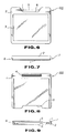
- Fig.6 is a front view showing the arrangement of the casing shown in Fig.4;
- Fig.7 is a back view showing the arrangement of the casing shown in Fig.4;
- Fig.8 is a bottom view showing the arrangement of the casing shown in Fig.4;
- Fig.9 is a front view showing the arrangement of the casing shown in Fig.4;
- Fig.10 is an exploded perspective view showing the arrangement of the casing shown in Fig.4;
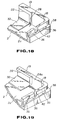
- Fig.11 is a perspective view, as seen from below, showing an arrangement of a top plate member constituting the casing for the disc cartridge shown in Fig.4;
- Fig.12 is a side view showing an arrangement of a top plate member;
- Fig.13 is a side view showing an arrangement of a top plate member constituting the casing for the disc cartridge;
- Fig.14 is a front view showing the shape of a top plate member constituting the casing for the disc cartridge shown in Fig.4;
- Fig.15 is a bottom view showing the shape of a top plate member.
- Fig.16 is a plan view showing the shape of a bottom plate member constituting the casing for the disc cartridge shown in Fig.4;
- Fig.17 is a front view showing the shape of the bottom plate member;
- Fig.18 is an enlarged partial perspective view of the bottom plate member shown in Fig.17;
- Fig.19 is an enlarged partial perspective view showing a modification of the bottom plate member;
- Fig.20 is an enlarged partial cross-sectional view showing the state of engagement of the top and bottom plate members at the lateral sides in the casing for the disc cartridge;
- Fig.21 is an enlarged partial cross-sectional view showing the state of engagement of the top and bottom plate members at the rear sides in the casing for the disc cartridge;
- Fig.22 is a perspective view showing another modification of the bottom plate member constituting the casing for the disc cartridge;
- Fig.23 is a perspective view, as seen from the front side, showing the shape of the locking member constituting the casing for the disc cartridge;
- Fig.24 is a perspective view, as seen from the rear side, showing the shape of the locking member;
- Fig.25 is a plan view showing the shape of the locking member shown in Fig.24;
- Fig.26 is a plan view showing the shape of a bottom plate member constituting the casing for the disc cartridge;
- Fig.27 is a perspective view showing the state of a first manner of mistaken insertion in the casing for the disc cartridge;
- Fig.28 is a perspective view showing the state of a second manner of mistaken insertion in the casing for the disc cartridge;
- Fig.29 is a perspective view showing the state of a third manner of mistaken insertion in the casing for the disc cartridge;
- Fig.30 is a transverse sectional view showing the state in which the disc cartridge is contained and held in the casing for the disc cartridge;
- Fig.31 is a longitudinal sectional view showing the state in which the disc cartridge is contained and held in the casing for the disc cartridge;
- Fig.32 is a longitudinal sectional view showing the state in which the disc cartridge is inserted in a mistaken manner into the casing and such mistaken insertion is inhibited;
- Fig.33 is a transverse sectional view showing the disc cartridge inserted in a mistaken manner into the casing for the disc cartridge;
- Fig.34 is a longitudinal sectional view showing the state in which the casing for the disc cartridge has been packaged with an overlap film;
- Fig.35 is a longitudinal sectional view showing a state in which the overlap film is shifted to one side from the state of Fig.34 when the casing for the disc cartridge is wrapped with the overlap film;
- Fig.36 is a longitudinal sectional view showing the state in which the overlap film is shifted to the opposite side from the state of Fig.34 when the casing for the disc cartridge is wrapped with the overlap film;
- Fig.37 is a transverse sectional view showing another state of packaging of the casing with an overlap film;
- Fig.38 is a longitudinal sectional view showing a state in which the overlap film is shifted to one side from the state of Fig.37 when the casing for the disc cartridge is wrapped with the overlap film;
- Fig.39 is a longitudinal sectional view showing the state in which the overlap film is shifted to the opposite side from the state of Fig.37 when the casing for the disc cartridge is wrapped with the overlap film;
- Fig.40 is a perspective view showing the state in which a label member is about to be applied to the casing when packaging the casing with an overlap film;
- Fig.41 is a perspective view showing the state in which a casing for a disc cartridge is packaged with an overlap film;
- Fig.42 is a perspective view showing a modified shape of the label member;
- Fig.43 is an enlarged partial perspective view showing the state in which the locking member of the casing for the disc cartridge according to a first modification of the invention is held by the bottom plate member;
- Fig.44 is an enlarged partial perspective view showing another modification of the locking member and the manner in which the locking member is held by the bottom plate member;
- Fig.45 is an enlarged partial plan view showing the state in which the locking member is held by the bottom plate member;
- Fig.46 is an enlarged partial plan view showing the state in which the bent arm of the locking member is flexed resiliently;
- Fig.47 is an enlarged partial perspective view showing another modification of a locking member constituting a casing for a disc cartridge according to the invention;
- Fig.48 is an enlarged partial plan view showing an arrangement of the locking member shown in Fig.47;
- Fig.49 is an enlarged perspective view showing the shape of essential part of the bottom plate member of the casing for the disc cartridge according to a fourth modification;
- Fig.50 is a perspective view showing the shape of the bottom plate member shown in Fig.49;
- Fig.51 is a longitudinal sectional view showing the state in which a disc cartridge is being inserted into the casing;
- Fig.52 is a longitudinal sectional view showing the state in which a disc cartridge has been inserted into the casing;
- Fig.53 is a side view showing the arrangement of a top plate member in a modification of the casing according to the invention;
- Fig.54 is aside view showing the arrangement of a bottom plate member in another modification of the casing according to the invention;
- Fig.55 is an enlarged partial cross-sectional view showing the engaged state at the rear side between the top plate member and the bottom plate member shown in Figs.53 and 54;
- Fig.56 is an exploded perspective view showing a disc cartridge constituted by the top plate member and the bottom plate member shown in Figs.53 and 54;
- Fig.57 is an enlarged perspective view showing the shape of essential parts of the bottom plate member shown in Fig.54;
- Fig.58 is an enlarged perspective view showing a modification of the shape of essential parts of the bottom plate member shown in Fig.54;
- Fig.59 is a longitudinal sectional view showing the manner in which the disc cartridge is inserted into the casing shown in Fig.56;
- Fig.60 is a longitudinal sectional view showing the manner in which the disc cartridge has been inserted into the casing shown in Fig.56.
- Fig.61 is an enlarged partial perspective view showing part of the top plate member of the casing to a fifth modification;
- Fig.62 is an enlarged partial perspective view showing essential part of the bottom plate member;
- Fig.63 is an enlarged partial longitudinal sectional view showing an arrangement of a blind hole of the casing for the disc cartridge;
- Fig.64 is an enlarged partial longitudinal sectional view showing part of the top plate member of the casing according to a fifth modification;
- Fig.65 is an enlarged partial longitudinal sectional view showing part of the top plate member of the casing according to a further modification;
- Fig.66 is an enlarged partial longitudinal sectional view showing part of the top plate member of the casing according to a still further modification; and
- Fig.67 is an enlarged cross-sectional view showing part of a metal mould for moulding the top plate member and the bottom plate member.
- Referring to the drawings, Fig.4 shows a
casing 100 for adisc cartridge 101 which includes a cartridgemain body 102 and a recording disc, such as an optical disc or a magneto-optical disc, accommodated therein. - The
disc cartridge 101 includes the cartridgemain body 102 made up of upper andlower halves recording disc 117 is housed for rotation within the cartridgemain body 102. - The
recording disc 117 includes a disc substrate formed of a synthetic resin and a signal recording layer deposited on one of the major surfaces of the disc substrate. Therecording disc 117 has acentre chucking aperture 114. The rim part of the chuckingaperture 114 on the major surface of the disc substrate serves as a chuckingreference surface 116. A chuckingplate 115 is mounted on the opposite major surface of the disc substrate for closing the chuckingaperture 114. - The cartridge
main body 102 is formed as a thin case having a substantially rectangular major surface having a side having a length substantially corresponding to the diameter of therecording disc 117. A pair of substantially rectangular recording/reproducingapertures main body 102. The recording/reproducingaperture 107 in thelower half 104 causes one of the major surfaces of therecording disc 117 to be exposed to outside across the inner and outer rims of thedisc 117. The recording/reproducingaperture 106 in theupper half 103 causes the other major surface of therecording disc 117 to be exposed to outside across the inner and outer rims of thedisc 117. - The recording/reproducing
apertures shutter member 105 slidably mounted on the cartridgemain body 102. Theshutter member 105 is formed from a thin metal sheet by bending it into a substantially U-shape and includes a pair of shutter plates for opening and closing the recording/reproducingapertures shutter member 105 has its centre web portion slidably supported by a lateral side of the cartridgemain body 102 so that the shutter plates are extended parallel to the major surfaces of the cartridgemain body 102. When theshutter member 105 is moved to a position in which the shutter plates are in register with the recording/reproducingapertures apertures shutter member 105 is slid rearwards with respect to the direction of introducing thedisc cartridge 101 into the recording/reproducing apparatus indicated by arrow A in Fig.4. The result is that theshutter member 105 has its shutter plates moved towards the rear on the major surface of the cartridgemain body 102 to open the recording/reproducingapertures - A
circular chucking aperture 108 is formed at a centre position on the lower major surface of the cartridgemain body 102. The chuckingaperture 108 causes the chuckingaperture 114, the chuckingreference surface 16 and thechucking plate 115 of therecording disc 117 to be exposed to outside. - The lower major surface of the cartridge
main body 102 has a pair ofpositioning holes main body 102. - The lower major surface of the cartridge
main body 102 is formed with a pair ofrecesses recesses recesses main body 102 so as to be open on the lateral sides of the cartridgemain body 102. The disc type discriminating recess 111 is formed on the front side in the lower major surface of the cartridgemain body 102 so as to be open on the front side of the cartridgemain body 102. The disc type discriminating recess 111 has its depth set depending on the type of therecording disc 117 housed in the cartridge main body. - The casing for the disc cartridge is made up of a top plate member 1 as a first member and a
bottom plate member 2 as a second member, as shown in Figs.4 and 6 to 10. - The top plate member 1 has a top plate section 1a of a size and shape substantially corresponding to the size and shape of the major surface of the cartridge
main body 102, and is integrally cast from e.g. a synthetic resin in the form of a flat plate. The top plate member 1 is formed of a light-transmitting material, such as acrylic resin, e.g. polymethacrylate, ABS resin, polycarbonate or polystyrene. - The top plate member 1 has a pair of
inner sidewall members rear wall member 15 parallel to the rear side of the top plate section 1a, as shown in Fig.11. Theinner sidewall members rear wall member 15 are cast as one with the top plate section 1a for defining a U-shaped peripheral wall interrupted at the front side. Thesesidewall sections rear wall section 15 are of a height substantially equal to the thickness of the cartridgemain body 102, and are inwardly offset from the lateral sides and the rear side of the top plate section 1a by a distance corresponding to the thickness of thewall sections - On the outer lateral sides of the
inner sidewall sections lateral engaging ribs ribs ribs lateral sidewall sections - On the outer lateral sides of the
inner sidewall sections retention projections retention projections inner sidewall sections ribs retention projections ribs retention projections sidewall sections sidewall sections - On the outer lateral sides of the
inner sidewall sections slits slits inner sidewall sections - On the lower surface of the top plate section 1a are formed a pair of
lateral shoulders rear shoulder 50 on both lateral sides and on the rear side, respectively. Theseshoulders 48 to 50 protrude only slightly to prevent thedisc cartridge 101 introduced into thecasing 100 from being slidingly contacted with the mid portion of the top plate section 1a. - A cut-
out 5 is formed on the front side of the top plate section 1a for causing the rear end of thedisc cartridge 101 housed within thecasing 100 to be exposed to outside. - The
bottom plate member 2 has abottom plate section 2a of substantially the same shape as the top plate section 1a and is cast as one from plastics or the like material. Thebottom plate member 2 is formed of a material showing excellent heat resistance, such as heat-resistant ABS resin or polycarbonate. - The
bottom plate member 2 has a pair ofouter sidewall members bottom plate section 2a, as shown in Fig.10. The bottom plate member 1 also has an outerrear wall member 19 parallel to the rear side of thebottom plate section 2a. Theouter sidewall members rear wall member 19 are cast as one with thebottom plate section 2a for defining a U-shaped peripheral wall interrupted at the front side. Theseouter sidewall sections rear wall section 19 are of a height substantially equal to the thickness of the cartridgemain body 102, and are formed for extending along the lateral sides and the rear side of thebottom plate section 2a. - In the inner lateral sides of the
outer sidewall sections lateral grooves grooves bottom plate section 2a from the vicinity of the front sides towards the rear sided of theouter sidewall members grooves outer sidewall sections bottom plate section 2a, with the upper ends of thegrooves rear wall member 19, that is the front lateral side, of the outerrear wall member 19, aflange 22 operating as a rear engaging lug is formed for being protruded towards the front side. Theflange 22 is provided for being extended from one towards the other lateral sides of the outerrear wall member 19 along the upper edge of the outerrear wall member 19 in parallel with the upper surface of thebottom plate section 2a. The lower lateral side of theflange 22 and thebottom plate section 2a make up an engaging rear groove. - In the inner lateral sides of the
outer sidewall sections retention projections outer sidewall members lateral grooves lateral grooves - In the upper lateral edges of the outer lateral surfaces of the
outer sidewall members recesses outer sidewall sections sidewall members recesses outer sidewall members - The rear portions of the
outer sidewall members outs vertical slits outs outer sidewall sections - The front side of the
bottom plate section 2a is formed with a cut-out 6 for causing a rear part of thedisc cartridge 101 housed within thecasing 100 to be exposed to outside. - On the lateral sides and the rear side of the
bottom plate 2a are formed a pair oflateral steps rear step 32, respectively. Thesesteps 30 to 32, having a small amount of protrusion, are used for preventing thedisc cartridge 101 from being slidingly contacted with the mid portion of thebottom plate section 2a when thedisc cartridge 101 is introduced into thecasing 100. - The
rear step 32 is formed with a mistakeninsertion inhibiting protrusion 29. This protrusion is formed at a position on the rear side of thebottom plate section 2a slightly offset from the centre towards a lateral side of thebottom plate section 2a. The function of the mistakeninsertion inhibiting protrusion 29 will be explained subsequently. - On both end parts of the
flange 22 are formed a pair of rib-shapedreinforcements flange 22, as shown in Figs.16 and 18. Thesereinforcements rear wall member 19 for extending from theflange 22 up to thebottom plate section 2a. At the lower parts within the engaginglateral grooves plural reinforcement ribs 43 for extending from the lateral sides of thegrooves bottom plate section 2a. - Meanwhile, the
reinforcements reinforcement 28a shown in Fig.19 is formed on the entire surface of theflange 22 of the outerrear wall member 19 and on both sides of the engaging rear groove. - The top plate member 1 and the
bottom plate member 2 are provided with step-shaped protrusions which are spaced apart from the sidewall members, as shown in Fig.22. Theseprotrusions bottom plate member 2 in parallel with theouter sidewall sections - The top plate member 1 and the
bottom plate member 2 are connected to each other by having thelateral engaging ribs lateral grooves rear engaging rib 16 engaged between theflange 22 and thebottom plate section 2a, that is in the engaging rear groove. For connecting the top plate member 1 and thebottom plate member 2 in this manner, the top plate member 1 is positioned ahead of thebottom plate member 2 and the rear sides of thelateral engaging ribs lateral grooves lateral engaging ribs lateral grooves bottom plate section 2a, therear engaging rib 16 is engaged in the rear engaging groove, while theretention projections retention projections retention grooves retention projections sidewall members outer sidewall members outer sidewall members retention projections outer sidewall members retention projections - The top plate member 1 and the
bottom plate member 2 are engaged with each other at the lateral sides and rear sides of the top plate section 1a and thebottom plate section 2a, with the top plate section 1a and thebottom plate section 2a extending parallel to each other, for defining an opening at the front side. This opening has a length substantially corresponding to the length of a side of the cartridgemain body 103, and a width substantially corresponding to the thickness of the cartridgemain body 102. The lower ends of theinner sidewall members rear wall member 15 are caused to bear against the upper surface of thebottom plate section 2a, while the upper ends of theouter sidewall members rear wall member 19 are caused to bear against the rim of the lower surface of the top plate section 1a. - The
recesses outer sidewall members lateral grooves outer sidewall members recesses lateral grooves casing 100. The rear bottom ends of thelateral grooves slits outer sidewall members vertical grooves inner sidewall members - Meanwhile, an injection gate of a metal mould for injection moulding the top plate member 1 is formed as a so-called pin gate at a position sightly offset towards the rear on the upper surface of the top plate section 1a, as shown at G1 in Fig.15. An injection gate of a metal mould for injection moulding the
bottom plate member 2 is formed as a so-called pin gate at a position sightly offset towards the rear on the lower surface of thebottom plate section 2a, as shown at G2 in Fig.16. That is, the top plate member 1 and thebottom plate member 2 are similar to each other in shape and the gate positions are in register with each other. Consequently, the top plate member 1 and thebottom plate member 2 are substantially similar in the state of deformation, such as shrinkage, caused by the cooling step during injection moulding, so that the engaging ribs of the sidewall sections may be engaged smoothly with each other. The injection gate may also be so-called film gates or submarine gates, instead of the pin gates. In these cases, the injection gates on the top plate member 1 and on thebottom plate member 2 may be positioned in register with each other to provide for a substantially equal state of deformation, such as shrinkage, to ensure smooth engagement of the top andbottom plate members 1 and 2. - At a recessed position within the space between the
members 1 and 2, a pair of lockingmembers disc cartridge 101 introduced between thesemembers 1 and 2. These lockingmembers resilient arm 46 spanning the end grips 44, 45, as shown in Figs.23 to 26. The end grips 44, 45 are columnar-shaped and have their axes parallel to each other. Theresilient arm 46 is arcuate in shape and interconnect the end grips 44, 45. Theresilient arm 46 is bent in a direction at right angles to the axes of thegrips bent arm 46 is at an equidistant position with respect to thegrips locking members disc cartridge 101. - The locking
members member mounting sections bottom plate member 2. These lockingmember mounting members outer sidewall sections sidewall members member protrusions protrusions outer sidewall members bottom wall section 2a. That is, these holdingprojections outer sidewall sections bottom plate section 2a. These holdingprotrusions locking members protrusions recesses members projections grips - These locking
members grips bottom plate section 2a and with the retention surfaces 47 directed towards the inner side of thebottom plate section 2a. That is, the arcuatelybent arms 46 of thelocking members bottom plate section 2a. The arcuatelybent arms 46 of these lockingmembers outer sidewall members arms 46 are resiliently deflected in this manner, thegrips - Meanwhile, the
inner sidewall sections locking members inner sidewall sections members member holding parts locking members member holding parts - It is noted that the back sides of the locking
member mounting parts outer sidewall members bottom plate member 2. Such sink is produced because the portions of theouter sidewall members member mounting parts outer sidewall members outer sidewall members member mounting parts clearances - For housing and holding the
disc cartridge 101 in the above-describedcasing 100 for a disc cartridge, the disc cartridge 1021 is introduced into the space between the top plate member 1a and thebottom plate member 2a from the front side via the opening in a direction shown by arrow A in Fig.4. - As the front side of the
disc cartridge 101 reaches the rear side of thecasing 101, the lateral surfaces of the front side of the cartridgemain body 102 thrust the retention surfaces 47, 48 of thelocking members arms outer sidewall members main body 102 reaches a predetermined position of being substantially abutted on the innerlateral wall 15 of thecasing 100, the lockingmembers recesses arms locking members recesses locking members recesses disc cartridge 101 is retained and limited in its movement of being detached rearwards, that is out of thecasing 100 via the opening under shock or vibrations. - The mistaken
insertion inhibiting protrusion 29 is fitted at this time in the disc discriminating recess 111 of thedisc cartridge 101, as shown in Fig.31. - The
disc cartridge 101, which is now in position within thecasing 100, is accommodated between and protected from outside by themembers 1 and 2. - When a plurality of
casings 100 are inserted into a rack adapted for containing plural casings, they are held in position by thelateral grooves casings 100 may be protected against accidental removal from the rack by engaging means provided on the rack being engaged in the bottomed openings formed by theslits - When the
disc cartridge 101 housed within thecasing 100 is to be taken out of thecasing 100, the rear part of thedisc cartridge 101 exposed to outside via the cut-outs casing 100. This causes the retention surfaces 47, 47 of thelocking members main body 102, while causing thearms locking members outer sidewall members 17. 18 for releasing the retention of thedisc cartridge 101. Thedisc cartridge 101 may now be taken out of thecasing 100 via the opening. As thedisc cartridge 101 is moved further rearwards, the lockingmembers disc cartridge 101 may be moved further rearwards so as to be taken out of thecasing 100. - The mechanism of preventing mistaken insertion of the disc cartridge into the casing will now be explained.
- The
casing 100 is designed to prevent thedisc cartridge 101 from being introduced up to the housing complete position within thecasing 100 even when thedisc cartridge 101 is inserted via the opening in the mistaken direction. - There are three possible cases of mistaken insertion of the
disc cartridge 101, namely the case in which thedisc cartridge 101 is inserted with its lower major surface facing upwards and with the front end side first, from the direction shown by arrow D in Fig.27, the case in which thedisc cartridge 101 is inserted with its lower major surface facing upwards and with the rear end side first, from the direction shown by arrow E in Fig.28, and the case in which thedisc cartridge 101 is inserted with its upper major surface facing upwards and with the rear end side first, from the direction shown by arrow F in Fig.29. - In any of these cases, when the
disc cartridge 101 is introduced into thecasing 100, the lockingmembers recesses locking members main body 102, as shown in Fig.33. If thelocking members members members - With the
present casing 100, if thedisc cartridge 101 is inserted in a mistaken manner as described above, the mistakeninsertion inhibiting protrusion 29 is caused to bear against the cartridgemain body 102 to inhibit the insertion thereof into thecasing 100, as shown in Fig.32. That is, the distance from the upper end face of the mistakeninsertion inhibiting protrusion 29 up to the lower surface of the top plate section 1a, as indicated by arrow L in Fig.32, is shorter than the thickness of the cartridgemain body 102 as indicated by arrow T in Fig.2. Consequently, the disc type discriminating recess 111 is not faced by the mistakeninsertion inhibiting protrusion 29. If theprotrusion 29 is not engaged with the recess 111, theprotrusion 29 is caused to bear against the cartridgemain body 102 to inhibit insertion of thedisc cartridge 101 into thecasing 100. Meanwhile, theprotrusion 29 has a height lower than the depth of the disc type discriminating recess 111. - The
casing 100 which has accommodated thedisc cartridge 101 therein as described above is packaged with anoverlap film 201 by a packaging method as shown in Figs.34 to 41. Theoverlap film 201 is a thermally contractible film which is contracted on being heated and which is melted on being heated further. - For packaging, a label member of
paper 204, which is to be a sheet-shaped member, is applied over the front end of thecasing 100 so as to cover up the cut-outs label member 203 is bent at its mid part into U-shape and applied to thecasing 100 to cover up the top plate section 1a and thebottom plate section 2a of thecasing 100. The two parallel bent portions of thelabel member 204 are located at substantially the mid positions of thelabel member 204 and are spaced apart from each other by a distance corresponding to the thickness of thecasing 100. With thelabel member 204 applied over thecasing 100, the latter presents a planar outer lateral surfaces. - Meanwhile, the
label member 204 is used as a so-called index label. Thelabel member 204, used as index label, is made up of a label coated with an adhesive and a release paper to which the label is bonded. - The wrapping is what is termed a caramel wrapping. First, the
casing 100 is introduced into the inside of anoverlap film 201 obtained by interconnecting two opposing edges of two film halves. Both end parts of theoverlap film 201 in the tubular form are bent inwards to form superposedsections superposed sections heating ironing members superposed sections casing 100. - The
heating ironing members members members recesses recesses casing 100 so that both lateral sides of thecasing 100 may be introduced up to the bottom of the recesses. Since the ridges of the lateral surfaces of thecasing 100 are rounded, both corners of therecesses - The
recesses casing 100 to be inserted therein. The result is that, if theoverlap film 201 is shifted in one or the other direction so that theoverlap film 201 has its one end extending over the entire lateral surface of thecasing 100 to reach the opposite side, that is the top late section 1a or thebottom plate section 2a, the extended portion of the overlap film may still be heated by the ironingmembers - The
overlap film 201 is heated and shrunk so as to be tightly applied to the outer surface of thecasing 100 to complete the wrapping, as shown in Fig.41. Since thecasing 100 presents a planar outer surface, theoverlap film 201 may be tightly applied to the outer lateral surface of thecasing 100 on which thelabel member 204 is applied previously. - Meanwhile, the
superposed portions overlap film 201 are applied to cover up thelateral grooves parts lateral grooves members - It may be a occurrence that the
overlap film 201 is partially positioned towards one or the other sides of thecasing 100, as shown in Figs.35 and 36. In these cases, one of the superposedparts lateral grooves lateral grooves superposed portions lateral grooves superposed portions - It is noted that the sheet-shaped member employed in the packaging method may also be a
label member 205 which will cover only the front side of thecasing 100, as shown in fig.2, instead of covering both the top plate section 1a and thebottom plate section 2a, as described above. Thelabel member 205 has two parallel folding lines and is bent into U-shape. The folded portion is offset towards one lateral side from the centre of thelabel member 205 and both the flaps are spaced part from each other by a distance corresponding to the thickness of thecasing 100. Thecasing 100 presents a planar outer surface when it is sheathed by thelabel member 205. - Various modifications of the casing for the disc cartridge are hereinafter explained. Those parts or components similar to those of the
casing 100 shown in Fig.4 are indicated by the same reference numerals and the corresponding description is omitted for simplicity. - A first modification of the casing for the disc cartridge is first explained. The locking
members member mounting parts bottom plate member 2. These lockingmember mounting parts outer sidewall members member mounting parts protrusions protrusions outer sidewall members bottom wall section 2a. That is, these holdingprojections outer sidewall sections bottom plate section 2a. These holdingprotrusions locking members protrusions recesses grips - The locking
members projections members grips bottom plate section 2a and with the retention surfaces 47 directed towards thebottom plate section 2a. That is, the arcuatelybent arms 46 of these lockingmembers bottom plate section 2a. - As shown in Fig.46, these locking
members outer sidewall members bent arms 46 are deflected resiliently in this manner, the end grips 44, 45 are moved in the fore-and-aft direction within the holding recesses 52, 53. Anabutment boss 58 is provided on the opposite side of theretention surface 47 of each of thelocking members arm 46 is resiliently deflected in a direction towards theouter sidewall members abutment boss 58 is abutted against the apex of anabutment rib 57 provided at a mid part of each of the lockingmember mounting parts arm 46 as shown in Fig.46. Therib 57 is formed for extending vertically between holdingprotrusions outer sidewall members - The
inner sidewall members sidewall members locking members inner sidewall members locking members member holding parts members member holding parts - The retention members in the
casing 100 for the disc cartridge may also be lockingmembers bent arm 46 is flattened at 56, in place of thelocking members - The mid parts of these locking
members recesses disc cartridge 101 is introduced into thecasing 100, the lockingmembers main body 102 for resiliently deflecting thebent arms 46. When the cartridgemain body 102 is inserted up to a predetermined position inside thecasing 100, thebent arms 46 are restored to their initial states for engaging the retention means in therecesses members recesses disc cartridge 101 from being disengaged from thecasing 100 under sock or vibrations. - Since the retention parts of the
locking members surfaces 56 are slid against the cartridgemain body 102 when thedisc cartridge 101 is introduced into thecasing 100 to ensure smooth and easy insertion of the disc cartridge into thecasing 100. - The retention members of the
casing 100 may also be designed as lockingparts 60 formed as one with thebottom plate member 2, instead of as the lockingmembers bottom plate member 2 shown in the preceding embodiments. This third modification of the casing for the disc cartridge is hereinafter explained. - These locking
parts 60 are paired and formed at the inner rear surfaces of theouter sidewall members parts 60 are formed at the lower portions ofouter sidewall members parts outer sidewall members parts 60 may be resiliently deflected in a direction towards theouter sidewall members outer sidewall members parts 60 to permit resilient deflection of these lockingparts 60. - The mid portions of these locking
parts 60 are bent in a substantially trapezoidal shape directed towards the inside of thebottom plate section 2a. The mid portions of the lockingparts 60 are formed as retention means engaged in therecesses disc cartridge 100 is introduced into thecasing 100, the lockingparts main body 102. When the cartridgemain body 102 is introduced up to a predetermined position within thecasing 100, the lockingparts 60 are restored to their original states to permit the retention means to be engaged in therecesses parts recesses disc cartridge 101 from being disengaged from thecasing 100 under shock or vibrations. - The retention means of the locking
part 60 has a frontinclined surface 62 facing the inserting direction of thedisc cartridge 101, shown by arrow C in Fig.48, which is sloped at a more moderate tilt than the opposite rear inclined surface in order to permit the lockingparts 60 to be resiliently deflected more readily when introducing or taking out thedisc cartridge 101 into or from thecasing 100. - A fourth modification of the casing for the disc cartridge is hereinafter explained.
- At the side of the locking
member 9 in the interior of thecasing 100, defined between theplate members 1 and 2, there is formed a lockingboss 70, which is to be a retention boss, as shown in Figs.49 and 50. The lockingboss 70 is formed as one with thebottom plate member 2. The lockingboss 70 is provided at a rear portion of theouter sidewall member 18. The lockingboss 70 is substantially semicylindrical-shaped and has its planar end face extending substantially parallel to thebottom plate section 2a and its semi-arcuate portion extending inwards from the lateral surface of theouter sidewall member 18. Theinner sidewall members sidewall members member 9 and a void equal to the height of the lockingboss 70, as shown in Fig.53. That is, theinner sidewall members member 9 held by the lockingmember holding part 33 and the lockingboss 70 while preventing these lockingmember 9 from being detached upwards from the lockingmember holding part 33. - For accommodating and holding the
disc cartridge 101 by thecasing 100 according to the above-described fourth embodiment, thedisc cartridge 101 is introduced via the opening in thecasing 100 from the front side, as shown by arrow A in Fig.4, into a space between the top plate section 1a and thebottom plate section 2a. - When the forward part of the
disc cartridge 101 reaches the rear end of thecasing 100, the forward end of the lateral surface of the cartridgemain body 102 facing the lockingmember 9 thrusts theretention surface 47 of the lockingmember 9 for deflecting thearm 46 towards theouter sidewall member 17. At this time, the forward end of the opposite lateral surface of the cartridgemain body 102 is caused to bear against the peripheral surface of the lockingboss 70 so as to be shifted slightly towards the lockingmember 9. When the forward of the cartridgemain body 102 is inserted up to a predetermined position in which it is substantially abutted against theinner sidewall section 15 of thecasing 100, the lockingmember 9 and the lockingboss 70 face therecesses arm 46 of the lockingmember 9 is restored at this time to its initial state under its own resiliency, with theretention surface 47 being intruded intorecess 109, as shown in Fig.52. The lockingmember 9 thrusts the cartridgemain body 102 towards the opposite side for introducing the lockingboss 70 into theopposite side recess 110. - The distance between the apex of the
retention surface 47 and that of the peripheral surface of the lockingboss 70, indicated by arrow Lc in Fig.52, is selected to be smaller than the width of the cartridgemain body 102, shown by arrow W in Fig.52. Consequently, with theretention surface 47 of the lockingmember 9 and the lockingboss 70 introduced into therecesses main body 102 is retained by being clamped from both lateral sides and thereby prevented from being disengaged via the opening of thecasing 100 towards outside under shock or vibrations. - The mistaken
insertion inhibiting protrusion 29 is engaged at this time in the disc type discriminating recess 111 of thedisc cartridge 101. - The
disc cartridge 101, thus accommodated in position within thecasing 100, is contained between and protected by theplate members 1 and 2. For taking out thedisc cartridge 101 out of thecasing 100, the rear parts of the disc cartridge exposed to outside via cut-outs casing 100. The lockingmember 9 then has itsretention surface 47 thrust by the front part of the lateral surface of the cartridgemain body 102 so that thearm 46 is flexed towards theouter sidewall member 17 to release retention of the cartridgemain body 102. At this time, thedisc cartridge 101 may be taken out of thecasing 100 via the opening. If thedisc cartridge 101 is moved further rearwards, the lockingmember 9 is reset to its initial state. Thedisc cartridge 101 may be taken out of thecasing 100 by pulling the disc cartridge outwards. - The
casing 100 for the disc cartridge may also be provided with a pair of lockingbosses member 9 and the lockingboss 70. These lockingbosses outer sidewall members bottom plate section 2a. These lockingbosses outer sidewall members bottom plate section 2a, as shown in Fig.57. - The
present casing 100 is not provided with theflange 22 providing therear engaging rib 16 and the rear engaging groove, with the outer lateral surface of the innerrear wall member 15 and the inner peripheral surface of the outerrear wall member 19 being planar, as shown in Figs.53 and 54. That is, with the lateral sidewall sections of the top plate member 1 and thebottom plate member 2 in engagement with each other, therear wall members - With the
present casing 100, thesidewall sections present casing 100 for the disc cartridge, the rear parts of the top plate member and the bottom plate member are resiliently flexed in a direction away from each other. Therear wall members - When the
disc cartridge 101 is introduced into thecasing 100 such that the forward end of thedisc cartridge 101 reaches the rear end of thecasing 100, both front lateral sides of the bottom plate section of the cartridgemain body 102 thrust the upper surface of the lockingbosses bottom plate section 2a downwards, that is away from the top plate section 1a. At this time, the rear parts of thelateral grooves main body 102 is introduced up to a predetermined position in which it is substantially abutted against the innerrear wall member 15 of thecasing 100, thebottom plate section 2a is faced by therecesses bottom plate section 2a is restored at this time under its own resiliency, as shown in Fig.60, with the lockingbosses recesses - The distance between end faces of the locking
bosses main body 102 indicated by arrow W in Fig.52. Consequently, by having the lockingbosses recesses main body 102 is retained by being clamped from both lateral sides and thereby prevented from being disengaged via the opening of thecasing 100 towards outside under shock or vibrations. - The
disc cartridge 101, thus accommodated in position within thecasing 100, is contained between and protected by theplate members 1 and 2. - For taking out the
disc cartridge 101 out of thecasing 100, the rear parts of the disc cartridge exposed to outside via cut-outs casing 100. The lockingmember 9 then has its lockingbosses main body 102 so that the rear part of thebottom plate section 2a is deflected in a direction away from the top plate section 1a to release retention of the cartridgemain body 102 by the lockingbosses disc cartridge 101 may be taken out of thecasing 100 via the opening. If thedisc cartridge 101 is moved further rearwards, the lockingmember 9 is reset to its initial state. Thedisc cartridge 101 may be taken out of thecasing 100 by pulling the disc cartridge outwards. - If, with the
present casing 100, a pair of locking bosses are formed at both inner lateral sides of the main casing member, these locking bosses may be substantially triangular-shaped with the triangular end faces extending parallel to theouter sidewall members bottom plate section 2a. - A fifth modification of the casing for the disc cartridge is hereinafter explained.
- In the rear outer lateral surfaces of the
inner sidewall members recesses 80, 81 defining bottomed holes. Theserecesses 80, 81 are formed as grooves extended vertically from the proximal sides up to the lower ends of theinner sidewall members inner sidewall members - In the rear parts of the
outer sidewall members bottom plate member 2 are formed a pair ofslits 82, 83 for defining a bottomed hole in register with therecesses 80, 81. Theseslits 82, 83 are formed in a direction from the upper ends towards the proximal ends of theouter sidewall members - On the other hand, recesses 37, 38 formed on the upper ends of the outer lateral surfaces of the
outer sidewall members lateral grooves outer sidewall members recesses lateral grooves casing 100. - Into these
lateral grooves casings 100. That is, the above-describedcasing 100 is supported by the rack by means of the supporting pieces by having the supporting pieces introduced into thelateral grooves - On the rear side of the bottom portions of these
lateral grooves slits 82, 83 in theouter sidewall members recesses 80, 81 in theinner sidewall members - These bottomed holes play the role of retaining the
casing 100 by having engaging members of the rack engaged therein. These bottomed holes are of a depth sufficient to permit the engaging members to be engaged therein. The depth of the bottomed holes, indicated by arrow G in Fig.63, corresponds to the depth of therecesses 80, 81 and the thickness of theouter sidewall members outer sidewall members inner sidewall members - A sixth embodiment of the casing for the disc cartridge is hereinafter explained. In the present modification, the
lateral grooves recesses outer sidewall members inner sidewall members inner sidewall members bottom plate section 2a and are provided on their outer sides with step-shapedabutments 85, as shown in Fig.64. Theouter sidewall members recesses outer sidewall members abutments 85, while being abutted against the outer lateral surfaces of the innerside wall members - If the
lateral grooves outer sidewall members inner sidewall members inner sidewall members abutments 85, as shown in Fig.65. In such case, theouter sidewall members inner sidewall members - The
lateral grooves recesses outer sidewall members inner sidewall members inner sidewall sections bottom plate section 2a and are provided on their outer sides with step-shapedabutments 86. Theouter sidewall members recesses outer sidewall members recesses abutments 86. Besides, the outer sidewall members are abutted against and support the outer lateral surfaces of theinner sidewall sections - Since the recesses making up the
lateral grooves upper mould 501 and alower mould 502 and which is not provided with a slide core, as shown in Fig.67. - With the present modification, since the lower ends of the
inner sidewall members bottom plate section 2a, the upper ends of theouter sidewall members outer sidewall members inner sidewall members
Claims (24)
- A casing (100) for a disc cartridge (101) comprising
a first half (1) having a square-shaped plate portion (1a), a pair of sidewall sections (11,12) formed along parallel sides of the plate portion (1a) and a rear wall section (15) defined between the sidewall sections (11,12),
first engaging means (13,14) formed on the sidewall sections,
second engaging means (16) formed on the rear wall section,
a second half (2) having a square-shaped plate portion (2a), a pair of sidewall sections (17,18) formed along parallel sides of the plate portion (2a) and a rear wall section (19) defined between the sidewall sections,
engaging means (20,21) formed on the sidewall sections (17,18) of the second half to engage the first engaging means (13,14),
engaging means (22) formed on the rear wall section (19) of the second half (2) to engage the second engaging means (16), and
holding means (9110) to hold a disc cartridge (101) in position within the casing. - A casing according to claim 1, including
locking means to lock the first and second halves together when the second engaging means are engaged with the means to engage the second engaging means. - A casing according to claim 1, wherein the first engaging means comprises projections and grooves formed parallel to the sides of the square-shaped plate portion of the first half, and wherein the means to engage the first engaging means comprises projections engaged in the grooves of the first engaging means and grooves engaged with the projections of the first engaging means, the projections being formed parallel to the grooves of the first engaging means.
- A casing according to claim 3, wherein the second engaging means comprises a projection formed on the distal end of the rear wall of the first half to be projected towards the inside of the first half and a recess formed between the square-shaped plate portion of the first half and the projection and wherein the means to engage the second engaging means comprise a projection projected at the distal end of the rear wall of the second half towards outside of the second half to be engaged in the recess of the first half and a recess formed between the projection of the second half and the square-shaped plate portion of the second half.
- A casing according to claim 1, including a pair of grooves on the outer lateral wall thereof.
- A casing according to claim 5, wherein the pair of grooves comprises the first engaging means and the means to engage the first engaging means.
- A casing according to claim 1, wherein the holding means include at least one holding means provided on said second half.
- A casing according to claim 7, wherein the second half further comprises a recess portion which is provided as the holding means, the recess portion being closed when the second engaging means and the means to engage the second engaging means are engaged with the holding means being contained by one of the lateral walls of a pair of lateral walls of the second half.
- A casing according to claim 1, wherein the holding means comprise a pair of holding portions formed in an inner side of the second half.
- A casing according to claim 1, wherein the holding means comprise a pair of holding portions formed in an inner side of the second half.
- A casing according to claim 6, wherein the second half further comprises mistaken insertion inhibiting means.
- A casing according to claim 5, wherein the second half further comprises reinforcement means to reinforce the rear wall.
- A casing for a disc cartridge comprising
a first half having a square-shaped plate portion, a pair of flanges formed along a pair of sides parallel to the square-shaped plate portion, a pair of sidewall sections formed parallel to the sides of the square-shaped plate portion and formed more inwardly than the edges of the square-shaped plate portion, a wall section offset more inwardly than the edge of the plate portion to interconnect the sidewall sections, and a plurality of flanges formed between the sidewall sections, the wall section and the square-shaped plate portion,
first engaging means formed on the sidewall sections of the first half,
second engaging means formed on the wall section of the first half,
a second half having a square-shaped plate portion and a pair of sidewall sections upstanding from parallel sides of the plate portion and a wall section upstanding from the square-shaped plate portion of the second half to interconnect the sidewall sections,
means formed on the sidewall sections to engage the first engaging means,
means formed on the wall section of the second half to engage the second engaging means, and
holding means to hold said disc cartridge in position within said casing. - A casing according to claim 13, including a pair of grooves formed on the outer lateral wall of the casing.
- A casing according to claim 14, wherein the sidewall sections are formed with cut-outs and wherein the grooves comprises the flange of the first half and the cut-outs of the second half.
- A casing according to claim 14, wherein the grooves are each formed with recess portions.
- A casing according to claim 13, wherein the first engaging means comprises projections and grooves formed parallel to the sides of the square-shaped plate portion of the first half, and wherein the means to engage the first engaging means comprises projections engaged in grooves of the first engaging means and grooves engaged in the projections of the first engaging means, the projections being formed parallel to the grooves of the first engaging means.
- A casing according to claim 17, wherein the second engaging means comprises a projection formed on the distal end of the rear wall of the first half to be projected towards the inside of the first half and a recess formed between the square-shaped plate portion of the first half and the projection and wherein the means to engage the second engaging means comprise a projection projected at the distal end of the rear wall of the second half towards outside of the second half to be engaged in the recess of the first half and a recess formed between the projection of the second half and the square-shaped plate portion of the second half.
- A casing according to claim 13, wherein the holding means includes at least one holding member provided at a corner which is formed by the wall and the plate portion of said portion of the second half.
- A casing according to claim 13, including mistaken insertion inhibiting means provided at a corner formed by the wall section and the plate portion of the second half.
- A casing according to claim 13, further comprising a pair of cut-outs formed inwardly of the plate portion from the sides paired to each of the walls of the first and second halves, one of the cut-outs being larger in size than the other.
- A packaging method for a casing having an opening and a cut-out formed from the opening to inner side of the casing, comprising the steps of applying a sheet-shaped member covering at least the opening and the cut-out, applying a film in a tubular form so that superposed portions are formed on the lateral sides of the casing, and heating the superposed portions to fuse the ends of the film.
- A packaging method according to claim 22, including the steps of the superposed portions to fuse the ends of the film and heating the entire assembly.
- A packaging method for a casing having an opening, a cut-out formed from the opening to an inner side of the casing and a pair of grooves formed on each of sidewalls of the casing, comprising the steps of
applying a sheet-shaped member covering at least the opening and the cut-out,
applying heat-shrinkable film so that superposed portions are formed at offset positions from the grooves on the lateral sides of the casing, and
heating the superposed portions to fuse the ends of the film.
Priority Applications (1)
| Application Number | Priority Date | Filing Date | Title |
|---|---|---|---|
| EP96119666A EP0768669B1 (en) | 1992-03-31 | 1993-03-25 | A method for packaging a casing |
Applications Claiming Priority (8)
| Application Number | Priority Date | Filing Date | Title |
|---|---|---|---|
| JP103960/92 | 1992-03-31 | ||
| JP10396092A JP3271080B2 (en) | 1992-03-31 | 1992-03-31 | Disk cartridge case |
| JP10396592A JP3189371B2 (en) | 1992-03-31 | 1992-03-31 | Disk cartridge case and packaging structure |
| JP103959/92 | 1992-03-31 | ||
| JP10395992A JP3331618B2 (en) | 1992-03-31 | 1992-03-31 | Disk cartridge case |
| JP103965/92 | 1992-03-31 | ||
| JP4103958A JP3039128B2 (en) | 1992-03-31 | 1992-03-31 | Packaging method |
| JP103958/92 | 1992-03-31 |
Related Child Applications (1)
| Application Number | Title | Priority Date | Filing Date |
|---|---|---|---|
| EP96119666A Division EP0768669B1 (en) | 1992-03-31 | 1993-03-25 | A method for packaging a casing |
Publications (3)
| Publication Number | Publication Date |
|---|---|
| EP0564155A2 true EP0564155A2 (en) | 1993-10-06 |
| EP0564155A3 EP0564155A3 (en) | 1994-05-18 |
| EP0564155B1 EP0564155B1 (en) | 1998-09-02 |
Family
ID=27469170
Family Applications (2)
| Application Number | Title | Priority Date | Filing Date |
|---|---|---|---|
| EP96119666A Expired - Lifetime EP0768669B1 (en) | 1992-03-31 | 1993-03-25 | A method for packaging a casing |
| EP93302262A Expired - Lifetime EP0564155B1 (en) | 1992-03-31 | 1993-03-25 | A casing to house a disc cartridge |
Family Applications Before (1)
| Application Number | Title | Priority Date | Filing Date |
|---|---|---|---|
| EP96119666A Expired - Lifetime EP0768669B1 (en) | 1992-03-31 | 1993-03-25 | A method for packaging a casing |
Country Status (9)
| Country | Link |
|---|---|
| US (3) | US5450952A (en) |
| EP (2) | EP0768669B1 (en) |
| KR (1) | KR100271552B1 (en) |
| CN (2) | CN1043630C (en) |
| AT (2) | ATE170661T1 (en) |
| AU (2) | AU665986B2 (en) |
| DE (2) | DE69332439T2 (en) |
| HK (1) | HK1013505A1 (en) |
| PH (1) | PH29973A (en) |
Cited By (9)
| Publication number | Priority date | Publication date | Assignee | Title |
|---|---|---|---|---|
| EP0632454A1 (en) * | 1993-05-31 | 1995-01-04 | Sony Corporation | Disc cartridge container casing |
| EP0666569A2 (en) * | 1994-02-07 | 1995-08-09 | Queens Group, Inc | Media disk storage container with printed paperboard sheets |
| US5450952A (en) * | 1992-03-31 | 1995-09-19 | Sony Corporation | Casing for housing disc cartridge and method for packaging the casing |
| EP0721186A1 (en) * | 1994-12-30 | 1996-07-10 | Shih-Hsien Lin | A compact disk carrying container |
| GB2318571A (en) * | 1996-10-26 | 1998-04-29 | Drum Enterprises Limited | A holder for a planar data storage medium |
| EP0895244A1 (en) * | 1997-07-31 | 1999-02-03 | Sony Corporation | Cartridge case |
| EP0977203A2 (en) * | 1998-07-30 | 2000-02-02 | Sony Corporation | Disc catridge storage case |
| US6182825B1 (en) | 1996-10-26 | 2001-02-06 | Digisox Limited | Holder for a planar data storage medium |
| EP1574454A1 (en) * | 2002-10-31 | 2005-09-14 | Matsushita Electric Industrial Co., Ltd. | Case |
Families Citing this family (16)
| Publication number | Priority date | Publication date | Assignee | Title |
|---|---|---|---|---|
| AU687123B2 (en) * | 1995-01-06 | 1998-02-19 | Shih-Hsien Lin | A compact disk carrying container |
| JPH08324669A (en) * | 1995-05-31 | 1996-12-10 | Sony Corp | Recording medium package |
| USD412261S (en) | 1995-07-20 | 1999-07-27 | Q2 Marketing, Llc | Video disk storage package |
| US6243350B1 (en) * | 1996-05-01 | 2001-06-05 | Terastor Corporation | Optical storage systems with flying optical heads for near-field recording and reading |
| DE29616895U1 (en) * | 1996-09-27 | 1996-12-12 | Siemens Ag | Transport container for relays |
| JPH10310187A (en) * | 1997-05-08 | 1998-11-24 | Tdk Corp | Cartridge housing case |
| US5954198A (en) * | 1997-10-28 | 1999-09-21 | Tdk Corporation | Cartridge receiving casing |
| US6095327A (en) * | 1998-02-02 | 2000-08-01 | Tdk Corporation | Storage case for cartridge, manufacturing method thereof and cartridge |
| JPH11232817A (en) * | 1998-02-09 | 1999-08-27 | Sony Corp | Housing case for disk cartridge |
| JP3519593B2 (en) * | 1998-02-27 | 2004-04-19 | Tdk株式会社 | Cartridge and cartridge storage case |
| JPH11321960A (en) | 1998-05-18 | 1999-11-24 | Sony Corp | Disk cartridge storage case |
| SG94718A1 (en) | 1998-05-23 | 2003-03-18 | Samsung Electronics Co Ltd | Cartridge for an information recording medium |
| JP2000355386A (en) * | 1999-06-09 | 2000-12-26 | Hitachi Maxell Ltd | Disk cartridge housing case |
| US7780048B2 (en) * | 2006-11-07 | 2010-08-24 | Howell Frank A | Hinged pocket |
| US8783455B2 (en) * | 2007-07-31 | 2014-07-22 | Ncr Corporation | Method and apparatus for storing a disc |
| JP6558377B2 (en) * | 2017-01-11 | 2019-08-14 | トヨタ自動車株式会社 | Packing structure for sheet heater and wire harness |
Citations (5)
| Publication number | Priority date | Publication date | Assignee | Title |
|---|---|---|---|---|
| FR2238211A1 (en) * | 1973-07-19 | 1975-02-14 | Paudras Francis | |
| DE2837610A1 (en) * | 1978-08-29 | 1980-03-06 | Orschler Produktion Kg | Display package for sale article esp cassette - has fastening, and two coaxial holes on opposite sides, in which pins fit onto shelf |
| WO1986007182A1 (en) * | 1985-05-23 | 1986-12-04 | Empak Inc. | A compact disc container |
| US4838422A (en) * | 1987-11-23 | 1989-06-13 | Empak, Inc. | Data storage container |
| WO1990005685A1 (en) * | 1988-11-21 | 1990-05-31 | Metcalf Darrell J | Computer diskette dispenser and storage device |
Family Cites Families (35)
| Publication number | Priority date | Publication date | Assignee | Title |
|---|---|---|---|---|
| US2289747A (en) * | 1940-05-10 | 1942-07-14 | Continental Can Co | Dispensing container |
| US2313667A (en) * | 1941-04-15 | 1943-03-09 | Schering Corp | Package for tablets, ampoules, and the like |
| US2638725A (en) * | 1950-05-12 | 1953-05-19 | Stadler Hurter & Company | Paper roll wrapping machine |
| GB1185635A (en) * | 1966-05-03 | 1970-03-25 | Emi Ltd | Improvements in or relating to Machines for Loading Thin Articles into Bags |
| GB1231352A (en) * | 1969-05-12 | 1971-05-12 | ||
| US3664088A (en) * | 1970-06-23 | 1972-05-23 | Olinkraft Inc | Package forming apparatus |
| US3760056A (en) * | 1970-09-23 | 1973-09-18 | Bogert R | Method for custom fitting an inflatable bladder to a wearer{3 s foot |
| US3808767A (en) * | 1971-01-11 | 1974-05-07 | Master Packaging Equipment Inc | Methods of and apparatus for shrink packaging |
| GB1388067A (en) * | 1972-08-10 | 1975-03-19 | Standard Telephones Cables Ltd | Hot rolled capacitors |
| JPS5249397B2 (en) * | 1972-09-29 | 1977-12-16 | ||
| CA1068166A (en) * | 1976-02-20 | 1979-12-18 | Robert E. Lockshin | Louvered window shade device |
| GB1596624A (en) * | 1976-12-20 | 1981-08-26 | Rca Corp | Record handling system for a disc player |
| AT356922B (en) * | 1978-09-04 | 1980-06-10 | Philips Nv | CASSETTE |
| US4266784A (en) * | 1979-11-28 | 1981-05-12 | Rca Corporation | Video disc caddy having disc entrapment |
| US4463850A (en) * | 1983-05-10 | 1984-08-07 | Rca Corporation | Video disc caddy |
| US4463849A (en) * | 1983-05-23 | 1984-08-07 | Rca Corporation | Video disc caddy |
| US4561544A (en) * | 1983-12-28 | 1985-12-31 | Calmar, Inc. | Child resistant container |
| FR2571169B1 (en) * | 1984-10-01 | 1987-01-09 | Posso Sa | BOX FOR STORAGE, PRESENTATION AND SELECTION OF DISCS OR OTHER MAGNETIC MEDIA. |
| US4627531A (en) * | 1985-03-07 | 1986-12-09 | Clemens Philip M | Recording disk enclosure |
| US4817369A (en) * | 1986-05-20 | 1989-04-04 | Machine Development Company, Inc. | Apparatus for envelope insertion and stacking |
| US5196978A (en) * | 1986-05-27 | 1993-03-23 | Sharp Kabushiki Kaisha | Cartridge case |
| EP0280053B1 (en) * | 1987-01-28 | 1993-12-15 | Fuji Photo Film Co., Ltd. | Sheet film package |
| DE3712803C2 (en) * | 1987-04-15 | 1996-06-13 | Elba Buerosysteme Erich Kraut | Device for storing data disks in registry media |
| KR0124147B1 (en) * | 1987-07-29 | 1997-11-28 | 나가이 아쯔시 | Disk cartridge |
| AU3819489A (en) * | 1988-07-22 | 1990-01-25 | Ede Babulik | Video tape cassette container |
| CN1054569A (en) * | 1990-03-07 | 1991-09-18 | 株式会社万代 | Packing chest, packaging body and packing method thereof |
| US5078128A (en) * | 1990-06-27 | 1992-01-07 | Royce Medical Company | Removable leg walker |
| JPH04214260A (en) * | 1990-12-12 | 1992-08-05 | Mitsubishi Electric Corp | Disk cartridge housing device |
| US5155973A (en) * | 1991-05-14 | 1992-10-20 | Webcraft Technologies, Inc. | Composite wrap and method for wrapping multi-page items |
| US5080222A (en) * | 1991-06-06 | 1992-01-14 | Tenax Corporation | Child resistant medicine box |
| IT1246011B (en) * | 1991-06-21 | 1994-11-07 | Gd Spa | METHOD AND DEVICE FOR THE REALIZATION OF COSTA JOINTS FOR CLOSURE OF PRODUCT WRAPS. |
| SG59941A1 (en) * | 1991-07-30 | 1999-02-22 | Okura Industrial Co Ltd | Thermally shrunk package |
| US5129538A (en) * | 1991-10-29 | 1992-07-14 | Olympic Plastics, Inc. | Container, usable as cash drawer |
| IT1253297B (en) * | 1991-10-31 | 1995-07-14 | Wrapmatic Spa | FILM RELEASE DEVICE APPLICABLE ON WELDERS OF PACKS OF ROLLS |
| AU665986B2 (en) * | 1992-03-31 | 1996-01-25 | Sony Corporation | Casing for housing disc cartridge and method for packaging the casing |
-
1993
- 1993-03-18 AU AU35326/93A patent/AU665986B2/en not_active Ceased
- 1993-03-25 EP EP96119666A patent/EP0768669B1/en not_active Expired - Lifetime
- 1993-03-25 EP EP93302262A patent/EP0564155B1/en not_active Expired - Lifetime
- 1993-03-25 DE DE69332439T patent/DE69332439T2/en not_active Expired - Fee Related
- 1993-03-25 DE DE69320676T patent/DE69320676T2/en not_active Expired - Fee Related
- 1993-03-25 AT AT93302262T patent/ATE170661T1/en not_active IP Right Cessation
- 1993-03-25 AT AT96119666T patent/ATE226751T1/en not_active IP Right Cessation
- 1993-03-30 PH PH45967A patent/PH29973A/en unknown
- 1993-03-31 KR KR1019930005242A patent/KR100271552B1/en not_active IP Right Cessation
- 1993-03-31 CN CN93105480A patent/CN1043630C/en not_active Expired - Fee Related
-
1994
- 1994-07-20 US US08/277,783 patent/US5450952A/en not_active Expired - Lifetime
-
1995
- 1995-02-17 US US08/390,101 patent/US5671590A/en not_active Expired - Fee Related
- 1995-11-10 AU AU37790/95A patent/AU676648B2/en not_active Ceased
-
1997
- 1997-02-19 US US08/804,027 patent/US5768855A/en not_active Expired - Fee Related
-
1998
- 1998-05-22 CN CN98109270A patent/CN1219735A/en active Pending
- 1998-12-22 HK HK98114867A patent/HK1013505A1/en not_active IP Right Cessation
Patent Citations (5)
| Publication number | Priority date | Publication date | Assignee | Title |
|---|---|---|---|---|
| FR2238211A1 (en) * | 1973-07-19 | 1975-02-14 | Paudras Francis | |
| DE2837610A1 (en) * | 1978-08-29 | 1980-03-06 | Orschler Produktion Kg | Display package for sale article esp cassette - has fastening, and two coaxial holes on opposite sides, in which pins fit onto shelf |
| WO1986007182A1 (en) * | 1985-05-23 | 1986-12-04 | Empak Inc. | A compact disc container |
| US4838422A (en) * | 1987-11-23 | 1989-06-13 | Empak, Inc. | Data storage container |
| WO1990005685A1 (en) * | 1988-11-21 | 1990-05-31 | Metcalf Darrell J | Computer diskette dispenser and storage device |
Cited By (15)
| Publication number | Priority date | Publication date | Assignee | Title |
|---|---|---|---|---|
| US5768855A (en) * | 1992-03-31 | 1998-06-23 | Sony Corporation | Casing for housing disc cartridge and method for packaging the casing |
| US5450952A (en) * | 1992-03-31 | 1995-09-19 | Sony Corporation | Casing for housing disc cartridge and method for packaging the casing |
| US5671590A (en) * | 1992-03-31 | 1997-09-30 | Sony Corporation | Casing for housing disc cartridge and method for packaging the casing |
| EP0632454A1 (en) * | 1993-05-31 | 1995-01-04 | Sony Corporation | Disc cartridge container casing |
| EP0666569A2 (en) * | 1994-02-07 | 1995-08-09 | Queens Group, Inc | Media disk storage container with printed paperboard sheets |
| EP0666569A3 (en) * | 1994-02-07 | 1995-08-16 | Queens Group, Inc | Media disk storage container with printed paperboard sheets |
| EP0721186A1 (en) * | 1994-12-30 | 1996-07-10 | Shih-Hsien Lin | A compact disk carrying container |
| GB2318571A (en) * | 1996-10-26 | 1998-04-29 | Drum Enterprises Limited | A holder for a planar data storage medium |
| US6182825B1 (en) | 1996-10-26 | 2001-02-06 | Digisox Limited | Holder for a planar data storage medium |
| EP0895244A1 (en) * | 1997-07-31 | 1999-02-03 | Sony Corporation | Cartridge case |
| US6019219A (en) * | 1997-07-31 | 2000-02-01 | Sony Corporation | Sleeve-type cartridge cases |
| EP0977203A2 (en) * | 1998-07-30 | 2000-02-02 | Sony Corporation | Disc catridge storage case |
| EP0977203A3 (en) * | 1998-07-30 | 2001-06-20 | Sony Corporation | Disc catridge storage case |
| EP1574454A1 (en) * | 2002-10-31 | 2005-09-14 | Matsushita Electric Industrial Co., Ltd. | Case |
| EP1574454A4 (en) * | 2002-10-31 | 2008-07-16 | Matsushita Electric Ind Co Ltd | Case |
Also Published As
| Publication number | Publication date |
|---|---|
| ATE170661T1 (en) | 1998-09-15 |
| US5768855A (en) | 1998-06-23 |
| EP0768669B1 (en) | 2002-10-23 |
| DE69332439D1 (en) | 2002-11-28 |
| ATE226751T1 (en) | 2002-11-15 |
| CN1043630C (en) | 1999-06-16 |
| DE69320676T2 (en) | 1999-03-11 |
| PH29973A (en) | 1996-10-03 |
| AU3532693A (en) | 1993-10-07 |
| EP0564155B1 (en) | 1998-09-02 |
| AU676648B2 (en) | 1997-03-13 |
| CN1081993A (en) | 1994-02-16 |
| US5671590A (en) | 1997-09-30 |
| DE69332439T2 (en) | 2003-08-14 |
| KR930020376A (en) | 1993-10-19 |
| US5450952A (en) | 1995-09-19 |
| EP0564155A3 (en) | 1994-05-18 |
| DE69320676D1 (en) | 1998-10-08 |
| CN1219735A (en) | 1999-06-16 |
| EP0768669A3 (en) | 1998-04-22 |
| AU665986B2 (en) | 1996-01-25 |
| KR100271552B1 (en) | 2000-11-15 |
| AU3779095A (en) | 1996-01-18 |
| EP0768669A2 (en) | 1997-04-16 |
| HK1013505A1 (en) | 1999-08-27 |
Similar Documents
| Publication | Publication Date | Title |
|---|---|---|
| EP0564155B1 (en) | A casing to house a disc cartridge | |
| EP0332214B1 (en) | A disk cartridge | |
| CA1227280A (en) | Magnetic tape cassette | |
| KR19990072481A (en) | disc cartridge container case | |
| JP3491427B2 (en) | Disk cartridge | |
| KR100444815B1 (en) | Disk cartridge case | |
| JP3123201B2 (en) | Disk cartridge case | |
| JP3331618B2 (en) | Disk cartridge case | |
| JP3106679B2 (en) | Disk cartridge case | |
| EP0632454A1 (en) | Disc cartridge container casing | |
| JP3039128B2 (en) | Packaging method | |
| JP3189371B2 (en) | Disk cartridge case and packaging structure | |
| JP3271080B2 (en) | Disk cartridge case | |
| JP3534073B2 (en) | Disk cartridge case | |
| JP3039129B2 (en) | Packaging method and packaging device | |
| JPH11321960A (en) | Disk cartridge storage case | |
| JP3123200B2 (en) | Disk cartridge case | |
| JP3136754B2 (en) | Disk cartridge case | |
| JP3136753B2 (en) | Disk cartridge case | |
| JP3534076B2 (en) | Storage case for disk cartridge | |
| JPH05305989A (en) | Disk cartridge case | |
| JPH06293377A (en) | Disk cartrideg case | |
| JP3853458B2 (en) | Storage case for mini disc cartridge | |
| JP3692152B2 (en) | Disc cartridge storage case | |
| JPH11349083A (en) | Storage case for disk cartridge |
Legal Events
| Date | Code | Title | Description |
|---|---|---|---|
| PUAI | Public reference made under article 153(3) epc to a published international application that has entered the european phase |
Free format text: ORIGINAL CODE: 0009012 |
|
| AK | Designated contracting states |
Kind code of ref document: A2 Designated state(s): AT DE FR GB |
|
| PUAL | Search report despatched |
Free format text: ORIGINAL CODE: 0009013 |
|
| AK | Designated contracting states |
Kind code of ref document: A3 Designated state(s): AT DE FR GB |
|
| 17P | Request for examination filed |
Effective date: 19941013 |
|
| 17Q | First examination report despatched |
Effective date: 19960710 |
|
| GRAG | Despatch of communication of intention to grant |
Free format text: ORIGINAL CODE: EPIDOS AGRA |
|
| GRAG | Despatch of communication of intention to grant |
Free format text: ORIGINAL CODE: EPIDOS AGRA |
|
| GRAH | Despatch of communication of intention to grant a patent |
Free format text: ORIGINAL CODE: EPIDOS IGRA |
|
| GRAH | Despatch of communication of intention to grant a patent |
Free format text: ORIGINAL CODE: EPIDOS IGRA |
|
| GRAA | (expected) grant |
Free format text: ORIGINAL CODE: 0009210 |
|
| AK | Designated contracting states |
Kind code of ref document: B1 Designated state(s): AT DE FR GB |
|
| REF | Corresponds to: |
Ref document number: 170661 Country of ref document: AT Date of ref document: 19980915 Kind code of ref document: T |
|
| XX | Miscellaneous (additional remarks) |
Free format text: TEILANMELDUNG 96119666.4 EINGEREICHT AM 07/12/96. |
|
| REF | Corresponds to: |
Ref document number: 69320676 Country of ref document: DE Date of ref document: 19981008 |
|
| ET | Fr: translation filed | ||
| PLBE | No opposition filed within time limit |
Free format text: ORIGINAL CODE: 0009261 |
|
| STAA | Information on the status of an ep patent application or granted ep patent |
Free format text: STATUS: NO OPPOSITION FILED WITHIN TIME LIMIT |
|
| 26N | No opposition filed | ||
| REG | Reference to a national code |
Ref country code: GB Ref legal event code: IF02 |
|
| PGFP | Annual fee paid to national office [announced via postgrant information from national office to epo] |
Ref country code: AT Payment date: 20070313 Year of fee payment: 15 |
|
| PGFP | Annual fee paid to national office [announced via postgrant information from national office to epo] |
Ref country code: GB Payment date: 20070321 Year of fee payment: 15 |
|
| PGFP | Annual fee paid to national office [announced via postgrant information from national office to epo] |
Ref country code: DE Payment date: 20070322 Year of fee payment: 15 |
|
| PGFP | Annual fee paid to national office [announced via postgrant information from national office to epo] |
Ref country code: FR Payment date: 20070308 Year of fee payment: 15 |
|
| GBPC | Gb: european patent ceased through non-payment of renewal fee |
Effective date: 20080325 |
|
| PG25 | Lapsed in a contracting state [announced via postgrant information from national office to epo] |
Ref country code: AT Free format text: LAPSE BECAUSE OF NON-PAYMENT OF DUE FEES Effective date: 20080325 |
|
| REG | Reference to a national code |
Ref country code: FR Ref legal event code: ST Effective date: 20081125 |
|
| PG25 | Lapsed in a contracting state [announced via postgrant information from national office to epo] |
Ref country code: DE Free format text: LAPSE BECAUSE OF NON-PAYMENT OF DUE FEES Effective date: 20081001 |
|
| PG25 | Lapsed in a contracting state [announced via postgrant information from national office to epo] |
Ref country code: FR Free format text: LAPSE BECAUSE OF NON-PAYMENT OF DUE FEES Effective date: 20080331 |
|
| PG25 | Lapsed in a contracting state [announced via postgrant information from national office to epo] |
Ref country code: GB Free format text: LAPSE BECAUSE OF NON-PAYMENT OF DUE FEES Effective date: 20080325 |