EP0559090B1 - Netzwerkelement mit Querverbindungsmatrix und Server - Google Patents
Netzwerkelement mit Querverbindungsmatrix und Server Download PDFInfo
- Publication number
- EP0559090B1 EP0559090B1 EP93103052A EP93103052A EP0559090B1 EP 0559090 B1 EP0559090 B1 EP 0559090B1 EP 93103052 A EP93103052 A EP 93103052A EP 93103052 A EP93103052 A EP 93103052A EP 0559090 B1 EP0559090 B1 EP 0559090B1
- Authority
- EP
- European Patent Office
- Prior art keywords
- overhead
- server
- signals
- data
- stm
- Prior art date
- Legal status (The legal status is an assumption and is not a legal conclusion. Google has not performed a legal analysis and makes no representation as to the accuracy of the status listed.)
- Expired - Lifetime
Links
- 239000011159 matrix material Substances 0.000 title claims description 58
- 230000006870 function Effects 0.000 description 35
- 238000004891 communication Methods 0.000 description 27
- 230000032258 transport Effects 0.000 description 21
- 238000012545 processing Methods 0.000 description 9
- 230000008901 benefit Effects 0.000 description 6
- 230000005540 biological transmission Effects 0.000 description 6
- 238000012423 maintenance Methods 0.000 description 5
- 238000013459 approach Methods 0.000 description 4
- 238000009826 distribution Methods 0.000 description 3
- 238000000034 method Methods 0.000 description 3
- 230000006855 networking Effects 0.000 description 3
- 230000008520 organization Effects 0.000 description 3
- 230000004044 response Effects 0.000 description 3
- 230000009471 action Effects 0.000 description 2
- 230000009977 dual effect Effects 0.000 description 2
- 238000009432 framing Methods 0.000 description 2
- 230000007774 longterm Effects 0.000 description 2
- 230000007246 mechanism Effects 0.000 description 2
- 238000012986 modification Methods 0.000 description 2
- 230000004048 modification Effects 0.000 description 2
- 238000012544 monitoring process Methods 0.000 description 2
- 102100040338 Ubiquitin-associated and SH3 domain-containing protein B Human genes 0.000 description 1
- 101710143616 Ubiquitin-associated and SH3 domain-containing protein B Proteins 0.000 description 1
- 230000002411 adverse Effects 0.000 description 1
- 230000008859 change Effects 0.000 description 1
- 239000012141 concentrate Substances 0.000 description 1
- 230000001934 delay Effects 0.000 description 1
- 230000001419 dependent effect Effects 0.000 description 1
- 238000009434 installation Methods 0.000 description 1
- 238000013507 mapping Methods 0.000 description 1
- 230000003287 optical effect Effects 0.000 description 1
- 230000008569 process Effects 0.000 description 1
- 230000008707 rearrangement Effects 0.000 description 1
- 230000008521 reorganization Effects 0.000 description 1
- 230000001360 synchronised effect Effects 0.000 description 1
Images


Classifications
-
- H—ELECTRICITY
- H04—ELECTRIC COMMUNICATION TECHNIQUE
- H04Q—SELECTING
- H04Q11/00—Selecting arrangements for multiplex systems
- H04Q11/04—Selecting arrangements for multiplex systems for time-division multiplexing
- H04Q11/0421—Circuit arrangements therefor
-
- H—ELECTRICITY
- H04—ELECTRIC COMMUNICATION TECHNIQUE
- H04J—MULTIPLEX COMMUNICATION
- H04J3/00—Time-division multiplex systems
- H04J3/16—Time-division multiplex systems in which the time allocation to individual channels within a transmission cycle is variable, e.g. to accommodate varying complexity of signals, to vary number of channels transmitted
- H04J3/1605—Fixed allocated frame structures
- H04J3/1611—Synchronous digital hierarchy [SDH] or SONET
-
- H—ELECTRICITY
- H04—ELECTRIC COMMUNICATION TECHNIQUE
- H04Q—SELECTING
- H04Q11/00—Selecting arrangements for multiplex systems
- H04Q11/04—Selecting arrangements for multiplex systems for time-division multiplexing
- H04Q11/0428—Integrated services digital network, i.e. systems for transmission of different types of digitised signals, e.g. speech, data, telecentral, television signals
- H04Q11/0478—Provisions for broadband connections
-
- H—ELECTRICITY
- H04—ELECTRIC COMMUNICATION TECHNIQUE
- H04J—MULTIPLEX COMMUNICATION
- H04J2203/00—Aspects of optical multiplex systems other than those covered by H04J14/05 and H04J14/07
- H04J2203/0001—Provisions for broadband connections in integrated services digital network using frames of the Optical Transport Network [OTN] or using synchronous transfer mode [STM], e.g. SONET, SDH
- H04J2203/0003—Switching fabrics, e.g. transport network, control network
- H04J2203/0005—Switching elements
-
- H—ELECTRICITY
- H04—ELECTRIC COMMUNICATION TECHNIQUE
- H04J—MULTIPLEX COMMUNICATION
- H04J2203/00—Aspects of optical multiplex systems other than those covered by H04J14/05 and H04J14/07
- H04J2203/0001—Provisions for broadband connections in integrated services digital network using frames of the Optical Transport Network [OTN] or using synchronous transfer mode [STM], e.g. SONET, SDH
- H04J2203/0003—Switching fabrics, e.g. transport network, control network
- H04J2203/0012—Switching modules and their interconnections
-
- H—ELECTRICITY
- H04—ELECTRIC COMMUNICATION TECHNIQUE
- H04J—MULTIPLEX COMMUNICATION
- H04J2203/00—Aspects of optical multiplex systems other than those covered by H04J14/05 and H04J14/07
- H04J2203/0001—Provisions for broadband connections in integrated services digital network using frames of the Optical Transport Network [OTN] or using synchronous transfer mode [STM], e.g. SONET, SDH
- H04J2203/0089—Multiplexing, e.g. coding, scrambling, SONET
-
- Y—GENERAL TAGGING OF NEW TECHNOLOGICAL DEVELOPMENTS; GENERAL TAGGING OF CROSS-SECTIONAL TECHNOLOGIES SPANNING OVER SEVERAL SECTIONS OF THE IPC; TECHNICAL SUBJECTS COVERED BY FORMER USPC CROSS-REFERENCE ART COLLECTIONS [XRACs] AND DIGESTS
- Y10—TECHNICAL SUBJECTS COVERED BY FORMER USPC
- Y10S—TECHNICAL SUBJECTS COVERED BY FORMER USPC CROSS-REFERENCE ART COLLECTIONS [XRACs] AND DIGESTS
- Y10S370/00—Multiplex communications
- Y10S370/901—Wide area network
- Y10S370/902—Packet switching
- Y10S370/903—Osi compliant network
- Y10S370/907—Synchronous optical network, SONET
Definitions
- This invention relates to telecommunications systems and, more particularly, to overhead processing of Synchronous Optical Network (SONET) signals.
- SONET Synchronous Optical Network
- the SONET overhead as defined in various standards, including ANSI T1.105, places some major constraints on any switching node in terms of the amount of bandwidth required. Initially, these requirements may be of much less significance, because of lesser usage of the full capacity of the SONET signal. Thus, the initial approach for architectures will probably not need to account for high usage, since the near term low usage with non-SONET interfaces would not justify it. For the long term, with more SONET interface usage, each switching node will have to contain appropriate equipment to efficiently address a fuller overhead functional usage.
- EP 0 437 197 A2 describes a digital cross-connection apparatus which comprises an input side interface unit having a plurality of inputs and an output side interface unit having a plurality of outputs.
- Input interface unit and output interface units are interconnected via a cross-connect matrix which is called switch unit. Operation of the interface units and of the switch unit are controlled by a controller unit over dedicated lines.
- the input interface transforms received input signals, so-called virtual tributaries (VT), to an internal transmission format by deviding them into whole integers. This enables the matrix to perform cross-connection by common hardware even if a plurality of types of VT signals having different VT sizes are input.
- VT virtual tributaries
- a modular cross-connection system which is capable of connecting input signals of different frame structures with lower rate signals. This is accomplished by converting all incoming signals into a substantially SONET format, and by processing all the signals in that format. If the outgoing signal is to be in other than SONET format, the substantially SONET format is reconverted into its outgoing format.
- a SONET line interface which receives and transmits SONET formatted signals, is connected to a mud/demur unit which spreads the SONET formatted signals into its virtual tributaries (VT) contained therein.
- the VT signals are fed to a virtual tributary cross-connection module, which cross-connects the VT signals in space, time, and phase to generate new substantially SONET formatted signals.
- a server is provided in a wideband digital cross-connect (such as a SONET cross-connect) for receiving a wideband signal (such as a SONET signal) and organizing the content thereof for distant transmission or for local subscriber use by way of a matrix in the digital cross-connect.
- the matrix may also be used for cross-connecting the so-organized SONET signal for overhead transmission and reception to/from other server functions, i.e., internal to the digital cross-connect.
- the wideband digital cross-connect switch disclosed in the above-mentioned co-pending application provides value-added functionality to a SONET network.
- An element that has been identified to implement some of the required functionality thereof, consistent with the requirements of providing flexibility, provision for future functional growth, modularity and fault tolerance is a server, according to the disclosure hereof.
- a server may be a self-contained element within the wideband digital cross-connect switch, other times called a SONET cross-connect, that contains its own necessary intelligence and interfaces for proper operation of assigned functions.
- Such servers are to be designed such that functionality can be partitioned in various ways such as logical, equipment geographical, efficient and standardized interfaces.
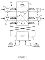
- a server 10 is shown in Fig. 1 as a part of a wideband digital cross-connect SWITCH (WDCS) 12, sometimes called a SONET cross-connect, including a cross-connect matrix, which may be a (VT) matrix 14, which may have a redundant mate (not shown), and a plurality of inputs 16 and outputs 18 for both SONET and non-SONET signals.
- the server 10 may consist, for example, of the following parts, as shown in Fig.
- switch modules 32 which may be packet switched modules for packet routing, orderwire modules 34 for circuit-switched orderwire line circuits, clocks 36 and power 38.
- External interfaces may include an O-interface 40 to the matrix 14, a control interface 42, an orderwire termination interface 44, a clock interface 46 and a power interface 48.
- the server 10 is interconnected within the wideband digital cross-connect switch 12 by means of an STM-1** signal and, as may be seen in Fig. 2, may be interconnected through redundant control links.
- the STM-1** signal is identical in overall structure to the STM-1 signal, except that some of the unused overhead bytes stripped off in the interfaces 16 are utilized within the switch 12 itself for internal housekeeping purposes.
- the overall structure of the STM-1** signal is shown in Fig. 4, to be discussed below, the details of which need not concern us here. It is also disclosed in French Patent Application 90 00991, filed January 29, 1990. (FR-A-2657741).
- the overhead information that is to be terminated in the WDCS 12 may be terminated in the input 16 or may be transported from any of the inputs 16 to the server 10, as indicated, for example, by path 50. That information, depending on the type, is either terminated in the user interface (e.g., orderwire) 44, or it is transported across the WDCS control interface 42 to the WDCS control system. Idle and undefined channels that are transported to the server 10 are terminated in the server.
- the overhead information that is to be terminated in any operating systems (OS) which may be connected to the WDCS is transported from an input 16 to the server as indicated by the path 50 and transported across the WDCS control interface to the WDCS control system.
- the WDCS control system will interface the information to the appropriate user, in this case the OS interface.
- the other category of information in the overhead is information that is to be transported across the WDCS system, such as from input 56 to output n 54.
- Examples of such would be data communications channel (DCC)(e.g., D1-D3) overhead packets from one external network element (NE) to another external NE.
- the overhead packet is transported from an input 56 to the server, as indicated by the path 50.
- the packet is then disassembled to the layer necessary to determine its destination.
- the packet Upon determining that its destination is required to pass through output n 54, the packet is reassembled and transported to output n by a path 58.
- DCC data communications channel
- NE external network element
- the organization of the STM-1** O-interface 40 that is the method of transport within the WDCS 12, may be a nine-row single column of bytes as the smallest switchable entity in the matrix.
- the STM-1** signal is a 155.520 Mb/s signal which interfaces the server 10 to the matrix 14.
- the format and content of the STM-1** at the interface 40 may be as shown in Fig. 4, for example.
- the overhead information is carried in columns 10-84 and 201-270. Framing is carried in row 1 of columns 1-6. Three columns contained in column 10-270 are to be reserved as STS-1 path overhead columns. All other byte locations are currently undefined.
- a set of overhead information that is transported may consist of a designated group of columns 1-9, such as STM-1 or similar, depending on the type of I/O signals and the optioned overhead that is to be transported to the server 10.
- Each column of overhead is an associated connection supervision (CSN) byte. This CSN byte is incremented for administration and maintenance of server to I/O connections.
- CSN connection supervision
- An overhead group of columns, associated with a specific I/O, may be mapped into the STM-1** legal payload areas such that, at the 0-interface 40, the columns are located at an interval of 3 or a multiple thereof (e.g., columns 10, 13 & 16, or 15, 21 & 24). That is, if the STM-1** is byte disinterleaved into 50 Mb signals, the overhead groups will be wholly contained in one of the 50 Mb signals.
- Overhead bytes must be preserved in a sequential manner in order to preserve the integrity of the information. That is, for a given DCC packet such as D1-D3, the three bytes are order dependent and must be processed in the server in the same order as they are received at the I/O.
- Undefined/unused and idle circuit-switched bytes in the overhead groups will be terminated with no further actions, and the generation thereof will be of value '0' transported to the I/Os. Idle packet channels will be properly terminated and generated in the packet switching units 32.
- the server will have one STM-1** access to the matrix 0 and one STM-1** access to the matrix 1. (Although for simplicity only one matrix 14 is shown in Fig. 1, it should be understood that there may be a second, redundant matrix provided.)
- the server 10 will process overhead channels from only one STM-1** access at a time.
- the server will determine the validity of the STM-1** connection by way of connection supervision bytes. If the STM-1** access is determined to be invalid by the server, the server will connect to the standby STM-1** access and check the validity of the standby.
- the server will switch back to the original STM-1** and report the results to the WDCS control system (not shown) through the interface 42. If the standby access is determined to be valid, the server will remain on the standby side and report the results to the WDCS control system.
- Internal protection circuits 20, 22 may be provided on both sides, such that a failure the server will have no impact on the WDCS system, with one exception, i.e., the failure of the internal protection unit itself. When this occurs, the WDCS will only be operational on the matrix side connected to the non-faulty internal protection unit. To accommodate the redundant matrix access principle, in the case of a failed internal protection unit, two STM-1** interfaces would be required per matrix side instead of one, each matrix side to both internal protection units. It is presumed, in the embodiment shown, that the equipment penalty and usage of STM-1**s to accommodate a double fault is not justified. However, such is, of course, possible.
- the server 10 provides packet switching and circuit switching functionality, as shown by modules 32, 34.
- the STM-1** signal must be able to be decomposed and circuit-switched down to the DS0 (64kb) signal level. It must be able to assign the circuit switching so as to preserve the integrity of the order of bytes, in particular for the packet-switching function.
- the server 10 is based on the principle that it is operating in a locked mode.
- the locked mode principle means that the location of the overhead bytes, after the columns have been assigned on the STM-1**, remain in fixed positions relative to the framing bytes. This implies that controlled slips of the overhead, if required due to plesiochronous signals at the I/Os relative to the WDCS, are accommodated in the I/Os.
- Loopback of any overhead channel is accommodated within the server for the high-speed STM-1** ports and the low-speed ports, such as the packet-switching modules 32.
- Broadcasting capability may be accommodated in the server. This provides the ability to broadcast a specific idle code to a multiple number of overhead channels.
- the idle code for non-packet overhead bytes may be an 'all-0' code.
- the server 10 is able to provide 64kb cross-connections within the STM-1** signals and to any termination interfaces within the server.
- the DS0 cross-connection capability is required for the termination of the orderwire channels as well as the termination of the OS channels to the server controller 28.
- any of the 64kb channels terminating on the server will be able to be rearranged and/or grouped for whatever the application/implementation reasons may be.
- server 10 complies with fairly stringent availability and reliability requirements, a basic principle adopted for redundancy/protection.
- the orderwire terminations need not be redundant, in that the n modules are selectable by the craft or OS, and failure of one unit is not critical.
- the packet-switching modules 32 are protected on an n+1 basis for economic reasons.
- Each side is connected to the matrix or to both matrices, if two are provided, through its respective internal protection unit 24, 26.
- the controllers 28, 30 may interface to the WDCS control system through respective A and B sides.
- the packet-switched modules and orderwire interfaces select the A or B side for termination upon commands from the control and transmit to both the A and B sides.
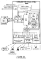
- the server 10 of Fig. 2 is shown in the form of two major sub-blocks 60, 62, comprising a protection and MUX/DEMUX functional block 60 and an overhead functional block 62.
- the redundancy feature of Fig. 2 has been incorporated in Fig. 3 by showing the redundant B side in some cases as a shadow block with shading behind the A block.
- the unit 60 shown in Fig. 3 includes an internal protection 68, 70 which interfaces the STM-1** to the WDCS matrix 14.
- 0-interface 40 itself is an external interface between the server 10 and the matrix 14. This interface operates at the standard 155.52 Mbps rate. This interface may transport the concentrated overhead.
- Each unit 68, 70 provides protection so that failures in the server 10 will not have adverse impact on the rest of the WDCS system 12. Also, when another subsystem, external to the server, should change operation to the standby side, it prevents the server from being forced to its standby side.
- Each of the OSIP units 68, 70 therefore provides an A/B selection mechanism which in the receive direction selects either A or B and in the transmit direction transmits identical signals.
- the internal protection unit synchronizes on the incoming STM-1** input, receives the STM-1** signal and provides two output STM-1** signals on a parallel bus to the MUX/DEMUX units 64, 66.
- the parallel bus is an internal interface that transports the STM-1** signals from the internal protection unit to the multiplexer/demultiplexer unit.
- the 155 Mb STM-1** signal is decomposed into a set of lower speed parallel buses.
- the OSIP receives two STM-1** parallel signals from the MUX/DEMUX units and transmits one of them to the WDCS matrix 14. The selection is made by the server controller 28.
- Clocks are sent to the OSIPs 68, 70 from the clock interface 46, and the remote inventory and management functions may be performed over a multi-processor serial interface (MSI) bus 72, such as A/B selection, loss of frame, etc.
- MSI multi-processor serial interface
- the multi-processor serial interface bus 72 may be an asynchronous serial interface which operates via stop and start bits, e.g. with a data rate of 128 kbps.
- the serial bus protocol may be based on the Intel Microcontroller Mode 2 operation. This is an asynchronous protocol which involves a start bit, eight data bits, program bit and stop bit.
- the multiplexer/demultiplexer 64 may, for example, multiplex and demultiplex the parallel STM-1** signals from internal protection unit 68 into a serial bus interface (SBI) 74 and on to mediator circuit switch (MCS) units 76, 78.
- the serial bus interface is an internal interface which operates at a rate of 4.096 MHz and is shown in more detail in U.S. Patent No. 5,060,229 to Tyrrell et al. However, another mode of connection may be used.
- SBI serial bus interface
- MCS mediator circuit switch
- the SBI-B is an SBI-link that is organized as a 64 8-bit (a byte) time-slot with B suffix indicating the byte-wide time-slot organization of the link.
- the SBI-B is a point-to-point carrier link from which bit and byte synchronization are recovered.
- Fig. 5 shows the organization of the SBI-B and SBI-E links.
- the SBI-E is an SBI link that is organized as 64 8-bit (a byte) time-slots, with E suffix indicating explicit timing signals.
- the SBI-E is not a point-to-point as the SBI-B, but rather a shared serial, tri-state bus with explicit timing signals defining bit, byte and addressing.
- the multiplexer/demultiplexers 64, 66 provide the same A/B selection function as the internal protection units 68, 70. Primarily, however, it maps, in a fixed pattern, the channels from the STM-1** to the SBI channels. Clocks are provided to this unit over the clock interface 46. Remote monitor and management functions are performed over the MSI bus 72, such as A/B selection, loss of frame, etc.
- the mediator circuit switch (MCS) 76, 78 performs the following primary functions for the server:
- the packet-switched modules 32 route packets through the server 10. They also provide for idle terminations and concentrate traffic. The packets are transmitted and received over the SBI buses 74 that are connected to the MCS 76, 78. The packet-switched modules communicate to the server control over a channel n in SBI bus 74.
- One of the packet-switched modules 32 is designated as the n+1 module in case of a module failure. When the n+1 module must take over for a failed module, the configuration and maps associated with the failed module are transported to the n+1 module by the server control 28.
- the orderwire interface 44 is an external interface between the dual orderwire units 34 and an orderwire termination circuit. This interface is a four-wire analog interface.
- the server control 28 operates on the input and output data as follows:
- the dual orderwire units 34 provide for the termination of active and selected local and express orderwires.
- a clock distribution 80, 82 provides all the necessary clocks for the server 10.
- Power supplies 84, 86 convert a negative 48-volt nominal station battery voltage to +5.0 and -5.2 voltage as required by the server 10.
- External power to the overhead server is redundant negative 48-volt office battery A and B. The distributions are individually fused outside the server 10.
- the WDCS control interface 42 is an external interface that connects the WDCS control to the server 10.
- a SONET cross-connect architecture with which a server, according to the present invention, may be used, is shown in Fig. 6.
- a basic concept of the architecture shown is to provide for common functional building blocks and standard interfaces that can be reused in the various elements of the SONET cross-connect (WDCS) and which may be even reused in other SONET-type products, such as interface elements and timeslot interchangers.
- WDCS SONET cross-connect
- the concept of the architecture as shown in Fig. 6 is for the SONET cross-connect to provide functional units identified as servers and intercommunication links.
- the concept is to have the following communication type of links:
- the concept of the STM-1** communication link is to allow for communication from server to server, server-to-interfaces and interfaces-to-interfaces by using available overhead bandwidth in the STM-1** frame.
- the primary function of this link is to provide a fixed information carrier based on the type of interfaces and servers identified. It takes advantage of the fact that some of the SONET overhead is terminated in the interfaces and therefore selected bytes are made available for intra-SONET cross-connect usage.
- the processors within the SONET cross-connect communicate over a communication link appropriate to the control architecture for the SONET cross-connect.
- the server-to-server data link provides for direct connection between servers where it is most appropriate to segregate functions into separate servers.
- a subservient server including a type n+1 server and a type n+2 server 110, 112, and an appropriate communication link 114 between the servers. This is to allow for flexibility, future functional growth, modularity and fault tolerance identified above.
- An appropriate example of a subservient server could be when a type n server 116 is a DS0 interchanger and the type n+2 server 112 is a termination unit for the orderwires and user channels. Termination of assignee's SONET products, for example, with the DS1 data link (TM, ADM, FTS, ...) could possibly terminate directly on this DS0 interchanger 116 or by way of an interface server such as the type n+2 server 112.
- the type n+1 server could be applicable for data communications packet handling and processing, where the datacom information is directed to it through the DS0 interchanger and communication with the SONET cross-connect 100 is accomplished over the processor communication link 114.
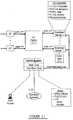
- Fig. 7 shows a DS0 organizer server 118 having a subservient packet server and orderwire server.
- the concept of providing pseudo-VTs, that contain floating overhead data can also be accommodated by this architecture.
- the overhead in the floating VTs could be handled by a server directly connected to the matrix by a STM-1**.
- This server would DEMUX/MUX the data by type and pass it on to subservient servers. It could also be passed through an intermediate DS0 interchanger as a VT1.5 between the matrix and the MUX/DEMUX.
- An administrative unit 118 shown in Fig. 6 is described in more detail below, and it is architecturally and functionally important here to provide for the completeness of the externally-imposed requirements of the network management aspects for the SONET cross-connect 100.
- DS0 matrix functions include section data communication channels (D1, D2 and D3), line (section) data communication channel (D4-D12), orderwire (E1 & E2), section user channel (F1), path user channel (F2), growth (Z1, Z2, Z3, Z4, Z5) and national use bytes (Xrc).
- the DS0 matrix function is provided by a server, allowing the capability to interchange and organize byte information into pseudo VT-1.5s which can be directed to other servers connected by STM-1** interfaces to the matrix.
- the server will provide the following functions:
- the received D1-D3 bytes will be mapped into the STM-1** frame for transport through the WDCS matrix to a server.
- the D bytes will be terminated in this server, which will provide the appropriate functions on the datacom channels, such as:
- the transmitted D1-D3 bytes will be mapped into the external SONET signal from the STM-1** frame that is transporting the D1-D3 bytes through the matrix.
- the bytes will originate from a server for information that originates in the WDCS and for the idle datacom channels.
- the byte information is generated external to the WDCS and routed through the appropriate DS0 interchanging server and routing server.
- Received Signal The received D4-D12 bytes will be mapped into the internal STM-1** frame for transport through the WDCS matrix to a server to be terminated and ignored.
- the transmitted D4-D12 bytes will be mapped into the external SONET signal from the internal STM-1** frame that is transporting the D4-D12 bytes through the WDCS matrix.
- a server will generate an idle pattern for the D4-D12 bytes and transmit them to the external SONET signal on the STM-1**.
- Received Signal The received E1 and E2 bytes will be mapped into the internal STM-1** frame for transport through the WDCS matrix.
- a switched circuit function will be performed in a server which receives selection commands form network management. Orderwires that have been selected by network management will be terminated to an external four-wire analog port. Termination of unselected orderwires will be terminated in the DS0 interchanging server.
- the transmitted E1 and E2 bytes will be mapped into the external SONET signal from the internal STM-1** frame that is transporting the E1 and E2 bytes through the WDCS matrix.
- a switched circuit function will be performed in the DS0 interchanger server which receives selection commands from network management. Orderwires that have been selected by network management will have the E1 and E2 bytes generated from information received from the external termination four-wire analog port. The E1 and E2 bytes from unselected orderwires will be generated in the DS0 interchanger server as idle codes.
- Received Signal The received F1 bytes will be mapped into the internal STM-1** frame for transport through the WDCS matrix to a server to be terminated and ignored.
- the transmitted F1 bytes will be mapped into the external SONET signal from the internal STM-1** frame that is transporting the F1 bytes through the WDCS matrix.
- a server will generate an idle pattern for the F1 bytes and transmit them to the external SONET signal on the STM-1**.
- Received Signal Requirement--When the path is matrixed to another SONET signal, the F2 bytes are transparently passed through the WDCS. Objective--When the path is matrixed to a non-SONET (ex. DS3) interface, the F2 bytes will be remapped at the non-SONET interface into the internal STM-1** frame for transport through the matrix to a server where they will be terminated and ignored. The received F2 bytes, when the path is terminated at the SONET interface, will be mapped into the internal STM-1** frame for transport through the WDCS matrix to a server where they will be terminated and ignored.
- Transmitted Signal Requirement--When the path is matrixed from another SONET signal, the F2 bytes are transparently passed through the WDCS on the path overhead. Objective--F2 bytes will be mapped into the external SONET signal from the internal STM-1** fame that is transporting the F2 bytes through the WDCS matrix.
- the non-SONET interface maps the idle F2 code onto the path overhead that it receives from the internal STM-1** from a server generating the idle code. For those signals terminating in the SONET interface, the idle code is received from a server over the STM-1**.
- Received Signal The received Z1 and Z2 bytes will be mapped into the internal STM-1** frame for transport through the WDCS matrix to a server to be terminated and ignored.
- the transmitted Z1 and Z2 bytes will be mapped into the external SONET signal from the internal STM-1** frame that is transporting the Z1 and Z2 bytes through the WDCS matrix.
- a server will generate an idle pattern for the Z1 and Z2 bytes and transmit them to the external SONET signal on the STM-1**.
- the Z3-Z5 bytes are transparently passed through the WDCS.
- the received Z3-Z5 bytes, when the path is terminated at the SONET interface will be mapped into the internal STM-1** frame for transport through the WDCS matrix to a server where they will be terminated and ignored.
- Transmitted Signal Requirement--When the path is matrixed from another SONET signal, the Z3-Z5 bytes are transparently passed through the WDCS on the path overhead. Objective--Z3-Z5 bytes will be mapped into the external SONET signal from the internal STM-1** frame that is transporting the Z3-Z5 bytes through the WDCS matrix.
- the non-SONET interface maps the idle Z3-Z5 code onto the path overhead that it receives from the internal STM-1** from a server generating the idle code. For those signals terminating in the SONET interface, the idle code is received from a server over the STM-1**.
- Fig. 8 shows the DS0 organizer server 118 of Fig. 7 in more detail.
- the elements of this server are to be redundant for reliability and availability requirements, as suggested in Fig. 7.
- the functions that it is to provide are:
- the orderwire server 138 of Fig. 8 is a subservient simplex server. It provides a simplex connection to the orderwire terminations. Redundant data links from the DS0 organizer server are brought in through line cards 146, 148.
- the server may be a modular unit and the line card growth requirement is thus flexible.
- the orderwires may be selected via network management, for example, by a craft command. If all orderwires require continuous on-line monitoring, an additional monitoring unit will be required.
- the packet server 142 of Fig. 8 is also a subservient server with redundant units.
- the functions that it performs are:
- AU administrative unit
- the administrative unit may perform functions associated with network management as follows:
- this interface is interfaced to the generic OSs and may interface to other products.
- This transparent interface will permit a number of logical channels to share a single physical OS interface.
- the generic OS interface may meet the requirements as defined in Bellcore TR-TSY-000828.
- the following physical interface may also be provided: EIA-232-D (supersedes RS-232) and V.35.
- the network manager/station control interface 154 may be the generic OS x .25 operations channel interface.
- the No. 2 SCCS IDCI interface is defined in Bellcore TR-TSY-000387. This interface requires 3 RS-232C channels from the SONET cross-connect to the 2SCCS: a maintenance IO channel, in emergency action interface control and display channel, and a critical indicator channel.
- the serial E2A interface (see Pub. 49001, Requirements for Compatibility of Telecommunications Equipment with Bell Systems Surveillance and Control Systems), provides surveillance and command through a serial data link from the SONET cross-connect to an alarm processing remote and the site location of the SONET cross-connect.
- the concentrated serial E2A (remote NEs), Ref. Pub. 49001, consolidates serial E2A surveillance and control for up to eight individual remote NEs into a single serial data link port to an alarm processing remote at the site location of the SONET cross-connect.
- a packet switch module is capable of supporting the packet switching of packets received from the subtending NEs via a DS1 link.
- the DS1 link is capable of carrying all the SONET overhead bytes from a subtending NE to the SONET cross-connect.
- the SONET cross-connect is capable of packet switching all of the SONET sectional or line DCCs from one attached NE to any of the DCCs of another attached NE. This includes the possibility of having to packet switch information from either a SONET line and/or section DCC or a single CCITT STM DCC (which is the concatenation of the line and section DCCs).
- At least one craft interface device port 150 provides a point suitable for maintenance access by local craft.
- the primary purposes of the local craft access port are installation and maintenance of the SONET cross-connect itself.
- the existence of the local craft access does not preclude operations on the SONET cross-connect from other craft access ports.
- craft is able to take priority via the local craft access over other access ports.
- the SONET cross-connect supports the craft dialog mode of TA-TSY-000204, the security features of TA-TSY-000308 and 000309.
- a centralized alarm-message display provides a point for displaying designated alarm messages arising autonomously from the sub-network on up to four separate craft interface devices.
- a server may be interconnected to a matrix such as the VT matrix 14 of Fig. 1 in various different ways.
- a single overhead server with a single STM-1** interface may be adequate for small cross-connect systems, or where there is a small amount of SONET overhead to be processed. If no additional capacity is ever needed, then the only sub-networking for the overhead is contained within the server itself. In this simplest configuration, the networking for the overhead is all handled in the one server and routed to any of the I/O ports.
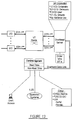
- a second configuration is where there are needs for more than one overhead server, as shown in Fig. 11, each with an STM-1** interface.
- a third configuration is a single server, as shown in Fig. 12, with multiple STM-1** interfaces. In this configuration, all the sub-networking that is necessary is contained in the architecture of the server.
- the configuration of Fig. 11 could be viewed as internal structures of this single server.
- FIG. 10 An example of a single server/single STM-1**, as shown in Fig. 10, is again shown in Fig. 13, with the networking for the overhead all handled in the one server and routed to any of the I/O ports.
- the illustration shows the straight-through transport of overhead through the matrix.
- Fig. 14 represents the situation of Fig. 10 showing terminating overhead from the input I/O No. 1 to the server No. 1 (the only server) (1) and from the server No. 1 to the output I/O No. 1 (2).
- Fig. 15 shows the structure of Fig. 10 in a mode terminating overhead from the input I/O No. 1 to the server No. 1 (1), and from the server No. 1 to the output I/O No. n (2).
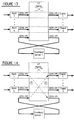
- a star network is shown in Figs. 16 and 17, where the center of the star is the VT matrix.
- m overhead servers are represented, each with their own STM-1** interfaces. I/Os are assigned to particular overhead servers. For the simple case of input No. 1 to output No. 1, the transport of overhead is the same as for a single server.
- the overhead on input No. 1 may be required to be transported to the output No. n, where the I/O No. n is allocated to the overhead server m. This could be the transmission of a data communications packet.
- the transport scenario, represented in Fig. 16, is that the overhead is transported from input No. 1 to overhead server No. 1 (1), from overhead server No. 1 to overhead server No. m (2), and from overhead server No. m to output No. n (3).
- Fig. 17 represents the situation where a particular function may be dedicated to a specific server, such as the orderwire terminations. In this case, additional transports through the VT matrix would be required.
- the overhead is transported from input No. 1 to overhead server No. 1, (1), from overhead server No. 1 to overhead server No. m (2), where it is terminated to the orderwire termination.
- the orderwire is transported from overhead server No. m to overhead server No. 1 (3), and from the overhead server No. 1 to the output No. 1 (4).
- the advantage of the star network interconnection of Figs. 16 and 17 is that the inter-server links are all contained within the VT matrix. No additional physical links are required. The unused bandwidth of the overhead STM-1** interface could be used for the intra-links. There is no dependency on determining the number of external links as a function of cross-connect size and overhead usage. Growth in size and functions is modular and flexible. The structure provides flexible link rearrangements through electronic memory mapping and, last but not least, it is the most cost-effective for multiple servers. The main disadvantage is that multiple passes through the VT matrix are required for various connections.
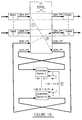
- a mesh network will next be considered in connection with Figs. 18 and 19, where each of the overhead servers is connected to all of the other overhead servers (m links) and each of the overhead servers has its own STM-1** interface. I/Os are assigned to particular overhead servers. For the simple case of input No. 1 to output No. 1, the transport of overhead is the same as for a single server.
- the overhead on input No. 1 may be required to be transported to the output No. n, where the I/O No. n is allocated to the overhead server m. This could be the transmission of a data communications packet.
- the transport scenario, represented in Fig. 18, is that the overhead is transported from input No. 1 to overhead server No. 1 (1), from overhead server No. 1 to overhead server No. m by way of an inter-server link (2), and from overhead server No. m to output No. n (3).
- Fig. 19 represents a situation where a particular function may be dedicated to a specific server, such as the orderwire terminations.
- the overhead is transported from input No. 1 to overhead server No. 1 (1), from overhead server No. 1 to overhead server No. m by way of an inter-server link (2), where it is terminated to the orderwire termination.
- the orderwire is transported from overhead server No. m by way of an inter-server link to overhead server No. 1 (3), and from the overhead server No. 1 to the output No. 1 (4).
- a ring network is shown in Figs. 20 and 21, where the overhead servers are connected to each other in a ring network of No. 1 to No. 2, . . . No. (m-1 to No. m, No. m to No. 1), and each of the overhead servers has its own STM-1** interface. I/Os are assigned to particular overhead servers. For the simple case of input No. 1 to output No. 1, the transport of overhead is the same as for a single server.
- the overhead on input No. 1 may be required to be transport to the output No. n, where the I/O No. n is allocated to the overhead server m. This could be the transmission of a data communications packet.
- the transport scenario, represented in Fig. 20, is that the overhead is transported from input No. 1 to overhead server No. 1 (1), from overhead server No. 1 to overhead server No. 2 by way of an inter-server link (2), from overhead server No. 2 to overhead server No. 3 by way of an inter-server link (3), . . ., from an overhead server No. (m-1) to overhead server No. m by way of an inter-server link (m), and from overhead server No. m to output No. n (m+1).
- Fig. 21 represents where a particular function may be dedicated to a specific server, such as the orderwire terminations.
- the overhead is transported from input No. 1 to overhead server No. 1 (1), from overhead server No. 1 to overhead server No. 2 by way of an inter-server link (2), from overhead server No. 2 to overhead server No. 3 by way of an inter-server link (3), . . ., from overhead server No. (m-1) to overhead server No. m by way of an inter-server link (m), where it is terminated to the orderwire termination.
- the orderwire is transported from overhead server No. m by way of an inter-server link to overhead server No. 1 (m+1), and from the overhead server No. 1 to the output No. 1 (m+2).
- the single server with multiple STM-1**s of Fig. 12 is identical to the single server/single STM-1**, except that all the STM-1**s interface to a single server. All of the sub-networkings therefore are contained within the server.
- the advantages are that there are no server-to-server links, and all overhead functions are contained in one overhead server.
- the disadvantage is that the architecture and implementation must accommodate from the minimum to maximum size required. This results in higher cost at the low end of cross-connect overhead usage.
Landscapes
- Engineering & Computer Science (AREA)
- Computer Networks & Wireless Communication (AREA)
- Signal Processing (AREA)
- Data Exchanges In Wide-Area Networks (AREA)
- Time-Division Multiplex Systems (AREA)
- Use Of Switch Circuits For Exchanges And Methods Of Control Of Multiplex Exchanges (AREA)
- Exchange Systems With Centralized Control (AREA)
- Small-Scale Networks (AREA)
- Optical Communication System (AREA)
Claims (9)
- Ein Netzelement (12), das folgendes umfaßt:Eine Vielzahl von Eingängen (16) zum Empfang von Eingangssignalen in einem Übertragungsformat, das sowohl einen Kopfteil als auch Daten umfaßt;Eine Vielzahl von Ausgängen (18) zur Übertragung von Ausgangssignalen in besagtem Übertragungsformat; undein Crossconnect-Koppelfeld (14), das auf besagte Eingangssignale reagiert, um besagte Eingangsdaten und Kopfteil-Signale in einem internen Übertragungsformat (STM-1**) bereitzustellen, und das auf besagte Ausgangsdaten und Kopfteil-Signale reagiert, um diese zu vermitteln,
gekennzeichnet durch
einen Server (10), der auf die Eingangsdaten und Kopfteil-Signale reagiert, um Eingangsdaten und Kopfteil-Signale selektiv zu entnehmen, und der auf Ausgangsdaten und Kopfteil-Signale reagiert, um die Ausgangsdaten und Kopfteil-Signale im internen Übertragungsformat (STM-1**) bereitzustellen; wobei besagter Server (10) mit besagtem Crossconnect-Koppelfeld (14) verbunden ist, um Eingangsdaten und Kopfteil-Signale von jedem der besagten Eingänge (16) in besagtem internen Übertragungsformat (STM-1**) zu empfangen und besagte Ausgangsdaten und Kopfteil-Signale zu jedem der besagten Ausgänge (18) zu übertragen. - Das Netzelement aus Anspruch 1, worin der Server (10) auf die eintreffenden Daten und Kopfteil-Signale an einer einzigen Schnittstelle reagiert, die das interne Übertragungsformat (STM-1**) aufweist.
- Das Netzelement aus Anspruch 1, worin der Server (10) auf die eintreffenden Daten und Kopfteil-Signale an einer Vielzahl von Schnittstellen reagiert, von denen jede das interne Übertragungsformat (STM-1**) aufweist.
- Das Netzelement aus Anspruch 1, das weiterhin mehrere Server umfaßt von denen jeder auf verschiedene eintreffende Daten und Kopfteil-Signale an einer Vielzahl von entsprechenden Schnittstellen reagiert, von denen jede das interne Übertragungsformat (STM-1**) aufweist.
- Das Netzelement aus Anspruch 4, worin die mehreren Server in einem Sternnetz miteinander verbunden sind.
- Das Netzelement aus Anspruch 4, worin die mehreren Server in einem Maschennetz miteinander verbunden sind.
- Das Netzelement aus Anspruch 4, worin die mehreren Server in einem Ringnetz miteinander verbunden sind.
- Das Netzelement aus Anspruch 1, worin der Server folgendes umfaßt:Einen Multiplexer/Demultiplexer (64), der auf ausgewählte Daten- und Kopfteil-Signale in einem parallelen/seriellen Übertragungsformat reagiert, um serielle/parallele Daten und Kopfteile bereitzustellen; undEinen Zeitschlitz-Multiplexer (76), der auf die Daten und Kopfteile vom Multiplexer (64) im seriellen Format reagiert, um Endteilnehmern auf ausgewählten Zeitschlitzen ausgewählte Daten bereitzustellen, und der auf Daten- und Kopfteil-Signale von den ausgewählten Endteilnehmern reagiert, um Daten und Kopfteil-Signale von den Endteilnehmern im seriellen Format bereitzustellen, worin der Demultiplexer (64) außerdem reagiert, um dasselbe wie die parallelen Daten und Kopfteile bereitzustellen.
- Das Netzelement aus Anspruch 1, worin der Server folgendes umfaßt:Einen Multiplexer (64), der auf eintreffende parallele Daten und Kopfteil-Signale reagiert, um eintreffende Daten und serielle Kopfteil-Signale (74) bereitzustellen;Eine Leitungsvermittlung (76), die auf die eintreffenden seriellen Signale reagiert, um eintreffende vermittelte Daten und serielle Kopfteil-Signale bereitzustellen, und die auf abgehende Daten und serielle Kopfteil-Signale reagiert, um abgehende vermittelte Daten und serielle Kopfteil-Signale (74) bereitzustellen; undEinen Demultiplexer (64), der auf die abgehenden vermittelten Daten und serielle Kopfteil-Signale reagiert, um abgehende vermittelte parallele Daten und Kopfteil-Signale bereitzustellen.
Applications Claiming Priority (2)
| Application Number | Priority Date | Filing Date | Title |
|---|---|---|---|
| US844238 | 1992-03-02 | ||
| US07/844,238 US5365518A (en) | 1992-03-02 | 1992-03-02 | Sonet overhead server |
Publications (3)
| Publication Number | Publication Date |
|---|---|
| EP0559090A2 EP0559090A2 (de) | 1993-09-08 |
| EP0559090A3 EP0559090A3 (de) | 1995-03-29 |
| EP0559090B1 true EP0559090B1 (de) | 2000-08-09 |
Family
ID=25292196
Family Applications (1)
| Application Number | Title | Priority Date | Filing Date |
|---|---|---|---|
| EP93103052A Expired - Lifetime EP0559090B1 (de) | 1992-03-02 | 1993-02-26 | Netzwerkelement mit Querverbindungsmatrix und Server |
Country Status (8)
| Country | Link |
|---|---|
| US (1) | US5365518A (de) |
| EP (1) | EP0559090B1 (de) |
| AT (1) | ATE195396T1 (de) |
| AU (1) | AU661102B2 (de) |
| CA (1) | CA2090663C (de) |
| DE (1) | DE69329162T2 (de) |
| ES (1) | ES2148188T3 (de) |
| NZ (1) | NZ245918A (de) |
Families Citing this family (43)
| Publication number | Priority date | Publication date | Assignee | Title |
|---|---|---|---|---|
| JP2541107B2 (ja) * | 1993-06-30 | 1996-10-09 | 日本電気株式会社 | クロスコネクト用インタフェ―スおよび装置 |
| US5526359A (en) * | 1993-12-30 | 1996-06-11 | Dsc Communications Corporation | Integrated multi-fabric digital cross-connect timing architecture |
| GB9400057D0 (en) * | 1994-01-05 | 1994-03-02 | Plessey Telecomm | Telecommunications system |
| US5742605A (en) * | 1994-02-28 | 1998-04-21 | Sprint Communications Co., L.P. | Synchronous optical network using a ring architecture |
| JPH08102747A (ja) * | 1994-09-30 | 1996-04-16 | Toshiba Corp | 通信用lsi |
| US5923653A (en) * | 1995-04-21 | 1999-07-13 | Tektronix, Inc. | SONET/SDH receiver processor |
| US5751717A (en) * | 1996-03-08 | 1998-05-12 | Ericsson, Inc. | Subscriber line interface in a telecommunications exchange |
| US5732211A (en) * | 1996-04-29 | 1998-03-24 | Philips Electronics North America Corporation | Advanced data server having a plurality of rings connected to a server controller which controls the rings to cause them to receive and store data and/or retrieve and read out data |
| US5883898A (en) * | 1996-07-01 | 1999-03-16 | Alcatel Usa Sourcing, L.P. | Apparatus and method for mapping E1 signals into a digital cross-connect matrix space |
| US5886994A (en) * | 1996-07-01 | 1999-03-23 | Alcatel Usa Sourcing, L.P. | Apparatus and method for mapping high density E1 signals into a digital cross-connect matrix space |
| DE19640547B4 (de) * | 1996-10-01 | 2005-11-03 | Marconi Communications Gmbh | Verfahren und Einrichtung zur Durchschaltung von digitalen Signalen |
| US7301953B1 (en) | 1996-10-22 | 2007-11-27 | Sprint Communications Company L.P. | Method and system for transporting a secondary communication signal with a primary communication signal |
| US6011802A (en) * | 1996-10-22 | 2000-01-04 | Sprint Communications Co. L.P. | Method and system for conversion and transmission of communication signals |
| US7643500B1 (en) | 1996-10-22 | 2010-01-05 | Sprint Communications Company L.P. | Overhead replication for SONET signals |
| KR100211987B1 (ko) * | 1996-12-12 | 1999-08-02 | 이계철 | 2.5Gbps급 (STM-16) 입출력 링크와 링 망 연동 기능을 통합한 동기식 교차 연결 장치 |
| JP3765899B2 (ja) * | 1997-01-27 | 2006-04-12 | 富士通株式会社 | 伝送装置 |
| JP3573610B2 (ja) * | 1998-01-28 | 2004-10-06 | 富士通株式会社 | Sdh伝送システム及びsdh伝送システムにおけるフレーム伝送方法並びにsdh伝送装置 |
| US6366662B1 (en) | 1998-01-30 | 2002-04-02 | Alcatel Usa Sourcing, L.P. | System and method for alternative routing of subscriber calls |
| US6580709B1 (en) | 1998-04-29 | 2003-06-17 | Nec America, Inc. | Sonet system and method which performs TSI functions on the backplane and uses PCM buses partitioned into 4-bit wide parallel buses |
| US6667973B1 (en) | 1998-04-29 | 2003-12-23 | Zhone Technologies, Inc. | Flexible SONET access and transmission systems |
| US7139277B2 (en) * | 1998-07-22 | 2006-11-21 | Synchrodyne Networks, Inc. | Multi-terabit SONET switching with common time reference |
| US6721508B1 (en) | 1998-12-14 | 2004-04-13 | Tellabs Operations Inc. | Optical line terminal arrangement, apparatus and methods |
| US6747988B1 (en) * | 1999-02-26 | 2004-06-08 | Eci Telecom Ltd. | Switching system for telecommunications network |
| IL144059A0 (en) * | 2001-06-28 | 2002-04-21 | Lightscape Networks Ltd | Overhead handling method and system for high order data streams |
| JP3784682B2 (ja) * | 2001-09-26 | 2006-06-14 | 富士通株式会社 | 伝送装置 |
| US20030174739A1 (en) * | 2002-03-12 | 2003-09-18 | Gagnon Ronald J. | Termination equipment with an overhead processor programmable to pass through proprietary usage data in selected overhead data slots |
| US8867333B2 (en) | 2003-03-31 | 2014-10-21 | Alcatel Lucent | Restoration path calculation considering shared-risk link groups in mesh networks |
| US7643408B2 (en) | 2003-03-31 | 2010-01-05 | Alcatel-Lucent Usa Inc. | Restoration time in networks |
| US8296407B2 (en) | 2003-03-31 | 2012-10-23 | Alcatel Lucent | Calculation, representation, and maintenance of sharing information in mesh networks |
| US7646706B2 (en) * | 2003-03-31 | 2010-01-12 | Alcatel-Lucent Usa Inc. | Restoration time in mesh networks |
| US7689693B2 (en) | 2003-03-31 | 2010-03-30 | Alcatel-Lucent Usa Inc. | Primary/restoration path calculation in mesh networks based on multiple-cost criteria |
| ATE372617T1 (de) | 2003-11-17 | 2007-09-15 | Alcatel Lucent | Verfahren und vorrichtung zur durchführung der verbindung und der zugehörigen eingabe- /ausgabeverarbeitungsfunktionen in synchronen, digitalen, hierarchischen transportnoten |
| US8111612B2 (en) | 2004-04-02 | 2012-02-07 | Alcatel Lucent | Link-based recovery with demand granularity in mesh networks |
| US7586888B2 (en) | 2005-02-17 | 2009-09-08 | Mobitrum Corporation | Method and system for mesh network embedded devices |
| US7630736B2 (en) | 2005-10-11 | 2009-12-08 | Mobitrum Corporation | Method and system for spatial data input, manipulation and distribution via an adaptive wireless transceiver |
| US8411590B2 (en) | 2006-07-27 | 2013-04-02 | Mobitrum Corporation | Mesh network remote control device |
| US7801058B2 (en) | 2006-07-27 | 2010-09-21 | Mobitrum Corporation | Method and system for dynamic information exchange on mesh network devices |
| US8305935B2 (en) | 2006-07-27 | 2012-11-06 | Mobitrum Corporation | Method and system for dynamic information exchange on location aware mesh network devices |
| USRE47894E1 (en) | 2006-07-27 | 2020-03-03 | Iii Holdings 2, Llc | Method and system for dynamic information exchange on location aware mesh network devices |
| US8305936B2 (en) | 2006-07-27 | 2012-11-06 | Mobitrum Corporation | Method and system for dynamic information exchange on a mesh network in a vehicle |
| US8427979B1 (en) | 2006-07-27 | 2013-04-23 | Mobitrum Corporation | Method and system for dynamic information exchange on location aware mesh network devices |
| US8861379B2 (en) * | 2007-07-26 | 2014-10-14 | Verizon Patent And Licensing Inc. | Test automation for an integrated telephony call management service |
| US7792132B2 (en) * | 2008-12-10 | 2010-09-07 | Agere Systems Inc. | Framer/mapper/multiplexor device with 1+1 and equipment protection |
Family Cites Families (10)
| Publication number | Priority date | Publication date | Assignee | Title |
|---|---|---|---|---|
| US5101404A (en) * | 1988-08-26 | 1992-03-31 | Hitachi, Ltd. | Signalling apparatus for use in an ATM switching system |
| US5040170A (en) * | 1988-12-09 | 1991-08-13 | Transwitch Corporation | System for cross-connecting high speed digital signals |
| US5142529A (en) * | 1988-12-09 | 1992-08-25 | Transwitch Corporation | Method and means for transferring a data payload from a first SONET signal to a SONET signal of different frequency |
| US4967405A (en) * | 1988-12-09 | 1990-10-30 | Transwitch Corporation | System for cross-connecting high speed digital SONET signals |
| US5214642A (en) * | 1989-02-21 | 1993-05-25 | Hitachi, Ltd. | ATM switching system and adaptation processing apparatus |
| US5134614A (en) * | 1989-05-11 | 1992-07-28 | Alcatel Network Systems, Inc. | Sonet receive signaling translator |
| US5018132A (en) * | 1989-05-12 | 1991-05-21 | Alcatel Na Network Systems Corp. | SONET 4h byte receiver and filter |
| US5001708A (en) * | 1989-05-12 | 1991-03-19 | Alcatel Na | Sonet H4 byte generator |
| JPH03207197A (ja) * | 1990-01-09 | 1991-09-10 | Fujitsu Ltd | ディジタルクロスコネクト装置 |
| FR2657741B1 (fr) * | 1990-01-29 | 1992-04-03 | Cit Alcatel | Interface de restructuration de trames pour trains numeriques multiplexes par multiplexage temporel d'affluents numeriques a differents debits. |
-
1992
- 1992-03-02 US US07/844,238 patent/US5365518A/en not_active Expired - Lifetime
-
1993
- 1993-02-17 NZ NZ245918A patent/NZ245918A/en unknown
- 1993-02-24 AU AU33733/93A patent/AU661102B2/en not_active Ceased
- 1993-02-26 EP EP93103052A patent/EP0559090B1/de not_active Expired - Lifetime
- 1993-02-26 DE DE69329162T patent/DE69329162T2/de not_active Expired - Lifetime
- 1993-02-26 AT AT93103052T patent/ATE195396T1/de active
- 1993-02-26 ES ES93103052T patent/ES2148188T3/es not_active Expired - Lifetime
- 1993-03-01 CA CA002090663A patent/CA2090663C/en not_active Expired - Fee Related
Also Published As
| Publication number | Publication date |
|---|---|
| AU661102B2 (en) | 1995-07-13 |
| AU3373393A (en) | 1993-09-09 |
| EP0559090A3 (de) | 1995-03-29 |
| US5365518A (en) | 1994-11-15 |
| DE69329162T2 (de) | 2001-06-07 |
| CA2090663A1 (en) | 1993-09-03 |
| CA2090663C (en) | 1999-02-02 |
| EP0559090A2 (de) | 1993-09-08 |
| ES2148188T3 (es) | 2000-10-16 |
| ATE195396T1 (de) | 2000-08-15 |
| DE69329162D1 (de) | 2000-09-14 |
| NZ245918A (en) | 1995-09-26 |
Similar Documents
| Publication | Publication Date | Title |
|---|---|---|
| EP0559090B1 (de) | Netzwerkelement mit Querverbindungsmatrix und Server | |
| US5436890A (en) | Integrated multi-rate cross-connect system | |
| US5850387A (en) | Processor device for terminating and creating synchronous transport signals | |
| US6240087B1 (en) | OC3 delivery unit; common controller for application modules | |
| US6768745B1 (en) | Flexible SONET access and transmission system | |
| US6667973B1 (en) | Flexible SONET access and transmission systems | |
| US7173930B2 (en) | Transparent flexible concatenation | |
| US5355362A (en) | Digital loop carrier system | |
| US6317439B1 (en) | Architecture for a SONET line unit including optical transceiver, cross-connect and synchronization subsystem | |
| EP0451400B1 (de) | Verfahren und Vorrichtung zur Rekonfiguration von Verbindungen zwischen Funktionseinheiten eines Vermittlungssystems | |
| US6587470B1 (en) | Flexible cross-connect with data plane | |
| US6061328A (en) | Integrated multi-fabric digital cross-connect integrated office links | |
| US5161152A (en) | High-speed synchronous transmission line access terminal | |
| US6285673B1 (en) | OC3 delivery unit; bus control module | |
| EP0857401B1 (de) | Digitales breitband-crossconnect system | |
| EP0615367B1 (de) | Querverbindung eines kommunikationsnetzes | |
| JPH07255072A (ja) | 加入者系伝送装置 | |
| US5583855A (en) | Add/drop multiplexer apparatus | |
| US6580709B1 (en) | Sonet system and method which performs TSI functions on the backplane and uses PCM buses partitioned into 4-bit wide parallel buses | |
| US6363078B1 (en) | OC-3 delivery unit; path verification method | |
| US6389013B1 (en) | OC3 delivery unit; low level maintenance bus | |
| US7023848B2 (en) | Rearrangement of data streams | |
| US6608844B1 (en) | OC-3 delivery unit; timing architecture | |
| US20010053146A1 (en) | Processor device for terminating and creating synchronous transport signals | |
| US6567402B1 (en) | OC-3 delivery unit; switching matrix interface |
Legal Events
| Date | Code | Title | Description |
|---|---|---|---|
| PUAI | Public reference made under article 153(3) epc to a published international application that has entered the european phase |
Free format text: ORIGINAL CODE: 0009012 |
|
| AK | Designated contracting states |
Kind code of ref document: A2 Designated state(s): AT BE CH DE ES FR GB IT LI NL SE |
|
| PUAL | Search report despatched |
Free format text: ORIGINAL CODE: 0009013 |
|
| AK | Designated contracting states |
Kind code of ref document: A3 Designated state(s): AT BE CH DE ES FR GB IT LI NL SE |
|
| RAP1 | Party data changed (applicant data changed or rights of an application transferred) |
Owner name: ALCATEL N.V. |
|
| 17P | Request for examination filed |
Effective date: 19950428 |
|
| K1C1 | Correction of patent application (title page) published |
Effective date: 19930908 |
|
| K1C1 | Correction of patent application (title page) published |
Effective date: 19930908 |
|
| 17Q | First examination report despatched |
Effective date: 19981102 |
|
| GRAG | Despatch of communication of intention to grant |
Free format text: ORIGINAL CODE: EPIDOS AGRA |
|
| RTI1 | Title (correction) |
Free format text: NETWORK ELEMENT COMPRISING A CROSS-CONNECT MATRIX AND A SERVER |
|
| GRAG | Despatch of communication of intention to grant |
Free format text: ORIGINAL CODE: EPIDOS AGRA |
|
| GRAH | Despatch of communication of intention to grant a patent |
Free format text: ORIGINAL CODE: EPIDOS IGRA |
|
| RAP1 | Party data changed (applicant data changed or rights of an application transferred) |
Owner name: ALCATEL |
|
| GRAH | Despatch of communication of intention to grant a patent |
Free format text: ORIGINAL CODE: EPIDOS IGRA |
|
| GRAA | (expected) grant |
Free format text: ORIGINAL CODE: 0009210 |
|
| AK | Designated contracting states |
Kind code of ref document: B1 Designated state(s): AT BE CH DE ES FR GB IT LI NL SE |
|
| PG25 | Lapsed in a contracting state [announced via postgrant information from national office to epo] |
Ref country code: NL Free format text: LAPSE BECAUSE OF FAILURE TO SUBMIT A TRANSLATION OF THE DESCRIPTION OR TO PAY THE FEE WITHIN THE PRESCRIBED TIME-LIMIT Effective date: 20000809 Ref country code: LI Free format text: LAPSE BECAUSE OF FAILURE TO SUBMIT A TRANSLATION OF THE DESCRIPTION OR TO PAY THE FEE WITHIN THE PRESCRIBED TIME-LIMIT Effective date: 20000809 Ref country code: CH Free format text: LAPSE BECAUSE OF FAILURE TO SUBMIT A TRANSLATION OF THE DESCRIPTION OR TO PAY THE FEE WITHIN THE PRESCRIBED TIME-LIMIT Effective date: 20000809 Ref country code: BE Free format text: LAPSE BECAUSE OF FAILURE TO SUBMIT A TRANSLATION OF THE DESCRIPTION OR TO PAY THE FEE WITHIN THE PRESCRIBED TIME-LIMIT Effective date: 20000809 Ref country code: AT Free format text: LAPSE BECAUSE OF FAILURE TO SUBMIT A TRANSLATION OF THE DESCRIPTION OR TO PAY THE FEE WITHIN THE PRESCRIBED TIME-LIMIT Effective date: 20000809 |
|
| REF | Corresponds to: |
Ref document number: 195396 Country of ref document: AT Date of ref document: 20000815 Kind code of ref document: T |
|
| REG | Reference to a national code |
Ref country code: CH Ref legal event code: EP |
|
| ITF | It: translation for a ep patent filed |
Owner name: JACOBACCI & PERANI S.P.A. |
|
| REF | Corresponds to: |
Ref document number: 69329162 Country of ref document: DE Date of ref document: 20000914 |
|
| REG | Reference to a national code |
Ref country code: ES Ref legal event code: FG2A Ref document number: 2148188 Country of ref document: ES Kind code of ref document: T3 |
|
| ET | Fr: translation filed | ||
| NLV1 | Nl: lapsed or annulled due to failure to fulfill the requirements of art. 29p and 29m of the patents act | ||
| REG | Reference to a national code |
Ref country code: CH Ref legal event code: PL |
|
| PLBE | No opposition filed within time limit |
Free format text: ORIGINAL CODE: 0009261 |
|
| STAA | Information on the status of an ep patent application or granted ep patent |
Free format text: STATUS: NO OPPOSITION FILED WITHIN TIME LIMIT |
|
| 26N | No opposition filed | ||
| REG | Reference to a national code |
Ref country code: GB Ref legal event code: IF02 |
|
| PGFP | Annual fee paid to national office [announced via postgrant information from national office to epo] |
Ref country code: IT Payment date: 20060228 Year of fee payment: 14 |
|
| PG25 | Lapsed in a contracting state [announced via postgrant information from national office to epo] |
Ref country code: IT Free format text: LAPSE BECAUSE OF NON-PAYMENT OF DUE FEES Effective date: 20070226 |
|
| PGFP | Annual fee paid to national office [announced via postgrant information from national office to epo] |
Ref country code: SE Payment date: 20110214 Year of fee payment: 19 |
|
| PGFP | Annual fee paid to national office [announced via postgrant information from national office to epo] |
Ref country code: ES Payment date: 20110222 Year of fee payment: 19 |
|
| PGFP | Annual fee paid to national office [announced via postgrant information from national office to epo] |
Ref country code: FR Payment date: 20120227 Year of fee payment: 20 |
|
| PGFP | Annual fee paid to national office [announced via postgrant information from national office to epo] |
Ref country code: DE Payment date: 20120221 Year of fee payment: 20 |
|
| PGFP | Annual fee paid to national office [announced via postgrant information from national office to epo] |
Ref country code: GB Payment date: 20120221 Year of fee payment: 20 |
|
| PG25 | Lapsed in a contracting state [announced via postgrant information from national office to epo] |
Ref country code: SE Free format text: LAPSE BECAUSE OF NON-PAYMENT OF DUE FEES Effective date: 20120227 |
|
| REG | Reference to a national code |
Ref country code: DE Ref legal event code: R071 Ref document number: 69329162 Country of ref document: DE |
|
| REG | Reference to a national code |
Ref country code: GB Ref legal event code: PE20 Expiry date: 20130225 |
|
| PG25 | Lapsed in a contracting state [announced via postgrant information from national office to epo] |
Ref country code: DE Free format text: LAPSE BECAUSE OF EXPIRATION OF PROTECTION Effective date: 20130227 Ref country code: GB Free format text: LAPSE BECAUSE OF EXPIRATION OF PROTECTION Effective date: 20130225 |
|
| REG | Reference to a national code |
Ref country code: ES Ref legal event code: FD2A Effective date: 20130708 |
|
| PG25 | Lapsed in a contracting state [announced via postgrant information from national office to epo] |
Ref country code: ES Free format text: LAPSE BECAUSE OF NON-PAYMENT OF DUE FEES Effective date: 20120227 |