EP0556563A2 - Internal combustion engine - Google Patents
Internal combustion engine Download PDFInfo
- Publication number
- EP0556563A2 EP0556563A2 EP93100539A EP93100539A EP0556563A2 EP 0556563 A2 EP0556563 A2 EP 0556563A2 EP 93100539 A EP93100539 A EP 93100539A EP 93100539 A EP93100539 A EP 93100539A EP 0556563 A2 EP0556563 A2 EP 0556563A2
- Authority
- EP
- European Patent Office
- Prior art keywords
- rotor
- bores
- internal combustion
- shaft
- housing
- Prior art date
- Legal status (The legal status is an assumption and is not a legal conclusion. Google has not performed a legal analysis and makes no representation as to the accuracy of the status listed.)
- Withdrawn
Links
Images

Classifications
-
- F—MECHANICAL ENGINEERING; LIGHTING; HEATING; WEAPONS; BLASTING
- F02—COMBUSTION ENGINES; HOT-GAS OR COMBUSTION-PRODUCT ENGINE PLANTS
- F02B—INTERNAL-COMBUSTION PISTON ENGINES; COMBUSTION ENGINES IN GENERAL
- F02B53/00—Internal-combustion aspects of rotary-piston or oscillating-piston engines
-
- F—MECHANICAL ENGINEERING; LIGHTING; HEATING; WEAPONS; BLASTING
- F02—COMBUSTION ENGINES; HOT-GAS OR COMBUSTION-PRODUCT ENGINE PLANTS
- F02B—INTERNAL-COMBUSTION PISTON ENGINES; COMBUSTION ENGINES IN GENERAL
- F02B53/00—Internal-combustion aspects of rotary-piston or oscillating-piston engines
- F02B2053/005—Wankel engines
-
- Y—GENERAL TAGGING OF NEW TECHNOLOGICAL DEVELOPMENTS; GENERAL TAGGING OF CROSS-SECTIONAL TECHNOLOGIES SPANNING OVER SEVERAL SECTIONS OF THE IPC; TECHNICAL SUBJECTS COVERED BY FORMER USPC CROSS-REFERENCE ART COLLECTIONS [XRACs] AND DIGESTS
- Y02—TECHNOLOGIES OR APPLICATIONS FOR MITIGATION OR ADAPTATION AGAINST CLIMATE CHANGE
- Y02T—CLIMATE CHANGE MITIGATION TECHNOLOGIES RELATED TO TRANSPORTATION
- Y02T10/00—Road transport of goods or passengers
- Y02T10/10—Internal combustion engine [ICE] based vehicles
- Y02T10/12—Improving ICE efficiencies
Definitions
- the invention relates to an internal combustion engine that works on the principle of rotation and can be used in particular in motor vehicles.
- the Wankel motor Internal combustion engines that have only rotating parts instead of the crank mechanism are known.
- a motor is the Wankel motor.
- the inner circumference of the housing has the shape of a trochoid.
- the runner has the shape of an equilateral triangle with bulged sides.
- Three spaces are created between the housing and the rotor, which change as the rotor rotates.
- the rotor is moved via an eccentric shaft and a corresponding internal toothing.
- the housing is provided with an inlet duct, an outlet duct and a bore for fastening the spark plug. Cooling water spaces are provided in the middle part of the housing.
- a flywheel equipped with counterweights is arranged to compensate for the unbalance of the eccentric and rotor.
- the dimensions are chosen so that the eccentric shaft rotates three times as fast as the rotor.
- the working process of the Wankel engine corresponds to that of a four-stroke process. The working cycle is repeated in a room for 3 revolutions, but since three chambers are always effective at the same time, there is one working cycle for each revolution as in the two-stroke process.
- the disadvantage of the Wankel engine is, above all, its complicated design, which requires a high manufacturing effort. Another problem is the sealing of the engine. The slightest leakage already leads to a reduction in engine performance, to an increase in the toxic components in the exhaust gases and to an increased fuel and oil consumption.
- the unfavorable gas-air mixture distribution in the Wankel engine leads to a considerable increase in fuel consumption of approx. 20 to 30%. Due to the relatively large ratio of the combustion chamber surface to the chamber volume, the temperature of the chamber walls is so low that not all hydrocarbons burn completely and the proportion of toxic substances in the exhaust gases increases accordingly.
- Another disadvantage of the Wankel engine is that it requires a complex carburetor system due to its narrow speed range. The lack of elasticity of the engine in its operating behavior can only be compensated for by installing a special gearbox, a five-speed change gearbox. This is also required to compensate for the unfavorable torque curve.
- the object of the invention is to provide an internal combustion engine that works on the principle of rotation, which is easy to manufacture, guarantees absolute tightness, allows a further reduction of toxic components in the exhaust gases, its mass and dimensions compared to the Wankel engine significantly reduced can be characterized by a very good performance and requires only low fuel consumption.
- an internal combustion engine which consists of a cylindrical housing which can be closed on both sides and has an axially symmetrically mounted, rotatable shaft, three bores arranged symmetrically offset by 120 ° for the supply of the fuel-air mixture and three symmetrically offset by 120 ° arranged bores for the installation of the spark plugs and three bores arranged symmetrically offset by 120 ° for the discharge of the exhaust gases are provided.
- the housing has two rotor parts which form a rotor with four wedge-shaped chambers which can be changed in volume. The rotor parts can be set in motion and locked independently of one another, one after the other in one direction. The torque of the rotor parts can be transferred to the shaft.
- the two rotor parts each consist of an annular disk with two fins symmetrically attached to the disk on one side.
- the rotor parts can be pushed onto the shaft and the fins of one rotor part can be pushed into the spaces between the other rotor parts.
- the end faces of the slats are each slidable on the inside of the other disk.
- the rotor parts can be connected to the shaft via a mechanical coupling during rotation.
- the outer contours of the disks and lamellas lie against the inner surface of the housing.
- locking elements are arranged, which can be brought into engagement with the two rotor parts via a control mechanism.
- the locking elements for each rotor part are guided in six bores arranged symmetrically offset by 60 ° and can be snapped into corresponding recesses in the disk of one and the other rotor part by means of a compression spring.
- the holes for the arrangement of the locking elements can be machined radially in the housing or concentrically to the shaft in both covers of the housing.
- the new engine is characterized by a very simple construction. This makes it possible to reduce manufacturing costs considerably. All essential components of the motor have easy-to-grind cylindrical surfaces and can be easily manufactured with high precision.
- the seal of the engine does not cause any problems either. Almost absolute tightness can be achieved with conventional sealing elements.
- the special wedge-shaped design of the combustion chambers makes it possible to reduce the proportion of toxic exhaust gases, especially carbon monoxide, by around 30%.
- Another advantage of the engine is its small size.
- the dimensions of the motor according to the invention can be reduced by 30% compared to a Wankel motor of the same power. At the same time, this reduces the mass by approx. 40%. Due to the design principle of this motor, there are no unbalances during rotation as with the Wankel motor, which must be compensated for by a flywheel with counterweights.
- the new engine does not require a separate distribution system for the fuel-air mixture, since the rotor parts automatically close and open the holes provided for this purpose.
- the engine can be equipped with ignition and carburetor systems known per se.
- the engine can also be lubricated in a conventional manner.
- the engine is characterized by a very good price-performance ratio. Compared to the Wankel engine, the costs are 2.5 to 3 times lower and those for the piston engine are 1.5 to 2 times lower.
- a particular advantage of this engine is its high torque at low speeds. This enables rapid acceleration of motor vehicles equipped with this engine. The way the torque is transmitted to the shaft ensures low fuel consumption when driving motor vehicles with this engine at high speeds.
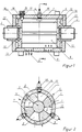
- the motor according to the invention is shown in longitudinal section.
- the motor consists of the housing 1 with an axially symmetrical shaft 2.
- the motor can be closed by push-on covers 16 on both ends.
- In the cylindrical housing 1 there are three holes 3 arranged symmetrically offset by 120 ° for the supply of the fuel air mixture, three holes 4 arranged symmetrically offset by 120 ° for the installation of the spark plugs 19 and three holes 5 arranged symmetrically offset by 120 ° for the discharge of the Exhaust gases provided.
- a rotor 6 with the two rotor parts 7, 8 forms four chambers 9, 10, 11, 12 with variable volume in the housing 1 (FIG. 2). These chambers have the shape of a wedge.
- the rotor parts 7, 8 each consist of an annular disk 13 with two fins 14 which are arranged symmetrically to one another.
- the inner surface 21 of the slats 14 is adapted to the radius of the shaft 2 ( Figure 3).
- a short flange 22 is also attached to the disk 13.
- the Rotor parts 7, 8 can be made from one part or from several parts, which are then assembled. The rotor parts 7, 8 are pushed onto the shaft 2 and are thereby nested so that the fins of one rotor part 7 fit into the free space between the fins of the other rotor part 8.
- the disks 13 with the lamellae 14 are designed in such a size that the lamellae of one rotor part slide with their end faces on the disk of the other rotor part and both the disks 13 and the lamellae 14 with their outer contour on the inner surface of the housing 1 slide. Due to the special design of the fins, four wedge-shaped chambers 9, 10, 11, 12 are thus formed in the motor housing, the volume of which can be changed by the different movement sequence of the rotor parts.
- the torque generated by the rotor parts 7, 8 is transmitted to the shaft 2 via a clutch 15. Since the two rotor parts 7, 8 do not rotate in one direction at the same time but only one after the other, one rotor part must be locked during the rotation of the other rotor part.
- each bores 17, which are arranged symmetrically offset by 60 °, are provided in the housing 1 in each case in which locking elements 18 are movably guided.
- the locking elements 18 engage in the recesses machined into the disks 13 and each lock the one or the other rotor part.
- the locking elements are set in motion by an automatic control device, not shown.
- balls 18 are shown as locking elements, which bring about the locking of the respective rotor part by means of a spring 20. It is also possible to lock and unlock the entire mechanism on the two attach the side covers of the housing.
- the holes for guiding the locking elements are then offset by 60 ° on a circular path in the two lids and the locking elements engage in corresponding recesses on the outer side of the disks.
- the expansion of the combustion gases in the chamber 12 causes the Rotation of the rotor part 8 causes the fuel / air mixture drawn in the chamber 9 to be compressed and the combustion gases still present in the chamber 11 to be expelled. At the same time, fuel-air mixture is drawn into the chamber 10 through the opened inlet valve. After reaching the required compression in the chamber 9, the fuel-air mixture is ignited and at the same time the rotor part 8 is locked and the rotor part 7 is unlocked. These processes are now repeated again and again and the rotor parts 7, 8 are in rotation. During the rotation of the rotor parts 7, 8, their torque via a clutch z. B. a ratchet clutch, transmitted to the shaft 2. The working cycle of the engine repeats itself after only 1/3 turn of the drive shaft.
- the motor can be equipped with water cooling in a manner known per se, a corresponding cooling jacket being arranged around the motor housing.
- a major advantage of the motor according to the invention lies in its torque curve.
- the torque increases when the speed is reduced. This characteristic corresponds to that of an electric motor.
- the low fuel consumption of the engine is achieved in that when the gas is removed, the idle speed is automatically set, the structural design of the engine does not require a change gearbox and the engine runs at idle speed at very low speeds, of approximately 100 rpm.
- the engine has a cylindrical working chamber and the rotor and the cylinder wall have a uniformly high temperature, which ensures complete combustion of the hydrocarbons. In connection with the low fuel consumption, it is possible to reduce the exhaust gases and their toxicity.
Landscapes
- Engineering & Computer Science (AREA)
- Chemical & Material Sciences (AREA)
- Combustion & Propulsion (AREA)
- Mechanical Engineering (AREA)
- General Engineering & Computer Science (AREA)
- Ignition Installations For Internal Combustion Engines (AREA)
- Supercharger (AREA)
Abstract
Description
Die Erfindung bezieht sich auf einen Verbrennungsmotor, der nach dem Rotationsprinzip arbeitet und insbesondere in Kraftfahrzeugen eingesetzt werden kann.The invention relates to an internal combustion engine that works on the principle of rotation and can be used in particular in motor vehicles.
Verbrennungsmotoren, die anstelle des Kurbeltriebs nur rotierende Teile besitzen, sind bekannt. Ein solcher Motor ist der Wankelmotor. Bei diesem hat der innere Umfang des Gehäuses die Form einer Trochoide. Der Läufer besitzt die Form eines gleichseitigen Dreiecks mit ausgebauchten Seiten. Zwischen dem Gehäuse und dem Läufer entstehen drei Räume, die sich bei Drehung des Läufers ändern. Der Läufer wird über eine Exzenterwelle und eine entsprechende Innenverzahnung bewegt.
Das Gehäuse ist mit einem Einlaßkanal, einem Auslaßkanal und einer Bohrung zur Befestigung der Zündkerze versehen. Im Gehäusemittelteil sind Kühlwasserräume vorgesehen. Zum Ausgleich der umlaufenden Unwucht von Exzenter und Läufer ist eine mit Gegengewichten ausgerüstete Schwungscheibe angeordnet. Die Abmessungen sind dabei so gewählt, daß sich die Exzenterwelle dreimal so schnell dreht wie der Läufer.
Das Arbeitsverfahren des Wankelmotors entspricht dem eines Viertaktverfahrens. Das Arbeitsspiel wiederholt sich in einem Raum auf 3 Umdrehungen, da jedoch drei Kammern immer gleichzeitig wirksam sind, kommt auf jede Umdrehung ein Arbeitsspiel wie beim Zweitaktverfahren. Der Nachteil des Wankelmotors ist vor allem seine komplizierte Gestaltung, die einen hohen Fertigungsaufwand erfordert. Ein weiteres Problem stellt die Abdichtung des Motors dar. Die geringsten Undichtheiten führen bereits zu einer Verringerung der Motorleistung, zu einer Erhöhung der toxischen Anteile in den Abgasen und zu einem erhöhten Treibstoff- und ölverbrauch.Internal combustion engines that have only rotating parts instead of the crank mechanism are known. Such a motor is the Wankel motor. In this case, the inner circumference of the housing has the shape of a trochoid. The runner has the shape of an equilateral triangle with bulged sides. Three spaces are created between the housing and the rotor, which change as the rotor rotates. The rotor is moved via an eccentric shaft and a corresponding internal toothing.
The housing is provided with an inlet duct, an outlet duct and a bore for fastening the spark plug. Cooling water spaces are provided in the middle part of the housing. A flywheel equipped with counterweights is arranged to compensate for the unbalance of the eccentric and rotor. The dimensions are chosen so that the eccentric shaft rotates three times as fast as the rotor.
The working process of the Wankel engine corresponds to that of a four-stroke process. The working cycle is repeated in a room for 3 revolutions, but since three chambers are always effective at the same time, there is one working cycle for each revolution as in the two-stroke process. The disadvantage of the Wankel engine is, above all, its complicated design, which requires a high manufacturing effort. Another problem is the sealing of the engine. The slightest leakage already leads to a reduction in engine performance, to an increase in the toxic components in the exhaust gases and to an increased fuel and oil consumption.
Die ungünstige Gas-Luft-Gemischverteilung im Wankelmotor führt zu einem erheblichen Mehrverbrauch an Kraftstoff von ca. 20 bis 30 %. Bedingt durch das relativ große Verhältnis von Verbrennungskammeroberfläche zum Kammervolumen ist die Temperatur der Kammerwände so niedrig, daß nicht alle Kohlenwasserstoffe vollständig verbrennen und sich demzufolge der Anteil an toxischen Stoffen in den Abgasen erhöht. Ein weiterer Nachteil des Wankelmotors ist, daß er infolge seines engen Drehzahlbereiches ein aufwendiges Vergasersystem benötigt. Auch die fehlende Elastizität des Motors in seinem Betriebsverhalten laßt sich nur durch den Einbau eines Spezialgetriebes, eines Fünfgangwechselgetriebes, ausgleichen. Dieses wird auch benötigt, um den ungünstigen Drehmomentenverlauf zu kompensieren.The unfavorable gas-air mixture distribution in the Wankel engine leads to a considerable increase in fuel consumption of approx. 20 to 30%. Due to the relatively large ratio of the combustion chamber surface to the chamber volume, the temperature of the chamber walls is so low that not all hydrocarbons burn completely and the proportion of toxic substances in the exhaust gases increases accordingly. Another disadvantage of the Wankel engine is that it requires a complex carburetor system due to its narrow speed range. The lack of elasticity of the engine in its operating behavior can only be compensated for by installing a special gearbox, a five-speed change gearbox. This is also required to compensate for the unfavorable torque curve.
Die Aufgabe der Erfindung besteht darin, einen Verbrennungsmotor, der nach dem Rotationsprinzip arbeitet zu schaffen, der einfach herstellbar ist, eine absolute Dichtheit garantiert, eine weitere Verringerung toxischer Anteile in den Abgasen ermöglicht, in seiner Masse und den Abmessungen im Vergleich zum Wankelmotor wesentlich reduziert werden kann, sich durch ein sehr gutes Leistungsverhalten auszeichnet und nur einen geringen Kraftstoffverbrauch erfordert.The object of the invention is to provide an internal combustion engine that works on the principle of rotation, which is easy to manufacture, guarantees absolute tightness, allows a further reduction of toxic components in the exhaust gases, its mass and dimensions compared to the Wankel engine significantly reduced can be characterized by a very good performance and requires only low fuel consumption.
Erfindungsgemäß wird die Aufgabe durch einen Verbrennungsmotor gelöst, der aus einem beidseitig verschließbaren zylindrischen Gehäuse mit einer achssymmetrisch gelagerten, rotierbaren Welle besteht, wobei in das Gehäuse jeweils drei symmetrisch um 120° versetzt angeordnete Bohrungen für die Zuführung des Treibstoffluftgemisches, drei symmetrisch um 120° versetzt angeordnete Bohrungen für den Einbau der Zündkerzen und drei symmetrisch um 120° versetzt angeordnete Bohrungen für die Abführung der Abgase vorgesehen sind. Auf der Welle innerhalb des Gehäuses sind zwei einen Rotor mit vier in ihrem Volumen veränderbaren, keilförmigen Kammern bildende Rotorteile angebracht. Die Rotorteile sind unabhängig voneinander, nacheinander in einer Richtung in Bewegung versetzbar und arretierbar.
Das Drehmoment der Rotorteile ist auf die Welle übertragbar. Entsprechend einer weiteren Ausgestaltung der Erfindung bestehen die beiden Rotorteile jeweils aus einer kreisringförmigen Scheibe mit zwei einseitig an der Scheibe symmetrisch befestigten Lamellen.
Die Rotorteile sind auf die Welle aufschiebbar und dabei sind die Lamellen des einen Rotorteiles in die Zwischenräume des anderen Rotorteiles schiebbar. Die Stirnseiten der Lamellen sind jeweils an der Innenseite der anderen Scheibe gleitbar ausgebildet. Die Rotorteile sind während der Rotation über eine mechanische Kupplung mit der Welle verbindbar. Die Außenkonturen der Scheiben und Lamellen liegen an der Innenoberfläche des Gehäuses an.
Zur Ver- und Entriegelung der beiden Rotorteile sind Arretierungselemente angeordnet, die über einen Steuermechanismus mit den beiden Rotorteilen in Eingriff bringbar sind. Die Arretierungselemente für jedes Rotorteil sind dabei in sechs symmetrisch um 60° versetzt angeordneten Bohrungen geführt, und mittels einer Druckfeder in entsprechende Ausnehmungen in der Scheibe des einen sowie des anderen Rotorteiles einrastbar. Die Bohrungen für die Anordnung der Arretierungselemente können radial im Gehäuse oder konzentrisch zur Welle in beiden Deckeln des Gehäuses eingearbeitet sein.
Im Vergleich zu Verbrennungsmotoren ähnlicher Bauart zeichnet sich der neue Motor durch einen sehr einfachen konstruktiven Aufbau aus. Dadurch ist es möglich, die Fertigungskosten beträchtlich zu senken. Alle wesentlichen Bauteile des Motors haben gut anschleifbare zylindrische Oberflächen und können mit hoher Präzision einfach hergestellt werden. Die Abdichtung des Motors bereitet ebenfalls keine Probleme. Mit herkömmlichen Dichtungselementen kann eine nahezu absolute Dichtheit erreicht werden.
Durch die spezielle keilförmige Ausbildung der Verbrennungskammern ist es möglich, den Anteil an toxischen Abgasen, insbesondere an Kohlenmonoxid, um ca. 30 % zu senken. Ein weiterer Vorteil des Motors sind seine geringen Abmessungen. Im Vergleich zu einem Wankelmotor gleicher Leistung kann der erfindungsgemäße Motor in seinen Abmessungen um 30 % reduziert werden. Gleichzeitig tritt dadurch eine Massereduzierung um ca. 40 % ein.
Bedingt durch das Konstruktionsprinzip dieses Motors, entstehen während der Rotation keine Unwuchten wie beim Wankelmotor, die durch eine mit Gegengewichten versehene Schwungscheibe auszugleichen sind.
Der neue Motor erfordert kein gesondertes Verteilungssystem für das Treibstoffluftgemisch, da durch die Rotorteile ein selbständiges Schließen und öffnen der dafür vorgesehenen Bohrungen erfolgt.
Der Motor kann mit an sich bekannten Zünd- und Vergasersystemen ausgerüstet werden. Auch die Schmierung des Motors kann nach herkömmlicher Art erfolgen. Der Motor zeichnet sich durch ein sehr günstiges Preis-Leistungsverhältnis aus. Im Vergleich zum Wankelmotor sind die Kosten um das 2,5- bis 3-fache und zum Kolbenmotor um das 1,5 bis 2-fache geringer.
Ein besonderer Vorteil dieses Motors ist sein hohes Drehmoment bei niedrigen Drehzahlen. Dadurch ist eine schnelle Beschleunigung von mit diesem Motor ausgerüsteten Kraftfahrzeugen möglich. Die Art der übertragung des Drehmomentes auf die Welle gewährleistet beim Fahren von Kraftfahrzeugen mit diesem Motor bei hohen Geschwindigkeiten einen geringen Kraftstoffverbrauch.According to the invention, the object is achieved by an internal combustion engine which consists of a cylindrical housing which can be closed on both sides and has an axially symmetrically mounted, rotatable shaft, three bores arranged symmetrically offset by 120 ° for the supply of the fuel-air mixture and three symmetrically offset by 120 ° arranged bores for the installation of the spark plugs and three bores arranged symmetrically offset by 120 ° for the discharge of the exhaust gases are provided. On the wave inside The housing has two rotor parts which form a rotor with four wedge-shaped chambers which can be changed in volume. The rotor parts can be set in motion and locked independently of one another, one after the other in one direction.
The torque of the rotor parts can be transferred to the shaft. According to a further embodiment of the invention, the two rotor parts each consist of an annular disk with two fins symmetrically attached to the disk on one side.
The rotor parts can be pushed onto the shaft and the fins of one rotor part can be pushed into the spaces between the other rotor parts. The end faces of the slats are each slidable on the inside of the other disk. The rotor parts can be connected to the shaft via a mechanical coupling during rotation. The outer contours of the disks and lamellas lie against the inner surface of the housing.
To lock and unlock the two rotor parts, locking elements are arranged, which can be brought into engagement with the two rotor parts via a control mechanism. The locking elements for each rotor part are guided in six bores arranged symmetrically offset by 60 ° and can be snapped into corresponding recesses in the disk of one and the other rotor part by means of a compression spring. The holes for the arrangement of the locking elements can be machined radially in the housing or concentrically to the shaft in both covers of the housing.
Compared to internal combustion engines of a similar design, the new engine is characterized by a very simple construction. This makes it possible to reduce manufacturing costs considerably. All essential components of the motor have easy-to-grind cylindrical surfaces and can be easily manufactured with high precision. The seal of the engine does not cause any problems either. Almost absolute tightness can be achieved with conventional sealing elements.
The special wedge-shaped design of the combustion chambers makes it possible to reduce the proportion of toxic exhaust gases, especially carbon monoxide, by around 30%. Another advantage of the engine is its small size. The dimensions of the motor according to the invention can be reduced by 30% compared to a Wankel motor of the same power. At the same time, this reduces the mass by approx. 40%.
Due to the design principle of this motor, there are no unbalances during rotation as with the Wankel motor, which must be compensated for by a flywheel with counterweights.
The new engine does not require a separate distribution system for the fuel-air mixture, since the rotor parts automatically close and open the holes provided for this purpose.
The engine can be equipped with ignition and carburetor systems known per se. The engine can also be lubricated in a conventional manner. The engine is characterized by a very good price-performance ratio. Compared to the Wankel engine, the costs are 2.5 to 3 times lower and those for the piston engine are 1.5 to 2 times lower.
A particular advantage of this engine is its high torque at low speeds. This enables rapid acceleration of motor vehicles equipped with this engine. The way the torque is transmitted to the shaft ensures low fuel consumption when driving motor vehicles with this engine at high speeds.
Die Erfindung soll nachstehend an einem Beispiel näher erläutert werden. In der zugehörigen Zeichnung zeigen
- Fig. 1
- einen Längsschnitt durch den Motor,
- Fig. 2
- einen Querschnitt durch den Motor gemäß der Linie A-A in Figur 1,
- Fig. 3
- ein Rotorteil im Längsschnitt,
- Fig. 4
- die Draufsicht auf das Rotorteil gemaß
Figur 3, - Fig. 5
- einen Querschnitt durch den Motor gemäß der Linie A-A in Figur 1 im Betriebszustand.
- Fig. 1
- a longitudinal section through the engine,
- Fig. 2
- 2 shows a cross section through the motor along the line AA in FIG. 1,
- Fig. 3
- a rotor part in longitudinal section,
- Fig. 4
- the top view of the rotor part according to Figure 3,
- Fig. 5
- a cross section through the motor along the line AA in Figure 1 in the operating state.
In der Figur 1 ist der erfindungsgemäße Motor im Längsschnitt dargestellt.
Der Motor besteht aus dem Gehäuse 1 mit einer achssymmetrisch gelagerten Welle 2. An seinen beiden Stirnseiten ist der Motor durch aufschiebbare Deckel 16 verschließbar. In dem zylindrischen Gehäuse 1 sind drei symmetrisch um 120° versetzt angeordnete Bohrungen 3 für die Zuführung des Treibstoffluftgemisches, drei symmetrisch um 120° versetzt angeordnete Bohrungen 4 für den Einbau der Zündkerzen 19 und drei symmetrisch um 120° versetzt angeordnete Bohrungen 5 für die Abführung der Abgase vorgesehen. Durch einen Rotor 6 mit den beiden Rotorteilen 7,8 werden in dem Gehäuse 1 vier in ihrem Volumen veränderbare Kammern 9, 10, 11, 12 gebildet (Figur 2). Diese Kammern besitzen die Form eines Keiles. Die Rotorteile 7,8 bestehen jeweils aus einer kreisringförmigen Scheibe 13 mit zwei Lamellen 14, die symmetrisch zueinander angeordnet sind. Die Innenfläche 21 der Lamellen 14 ist dem Radius der Welle 2 angepaßt (Figur 3). An der Scheibe 13 ist noch ein kurzer Flansch 22 angebracht. Die Rotorteile 7, 8 können aus einem Teil gefertigt werden oder aus mehreren Teilen, die dann zusammengebaut werden. Die Rotorteile 7, 8 werden auf die Welle 2 geschoben und dabei so ineinandergesetzt, daß die Lamellen des einen Rotorteiles 7 in den freien Raum zwischen den Lamellen des anderen Rotorteiles 8 passen.
Die Scheiben 13 mit den Lamellen 14 sind in ihrer Große so ausgebildet, daß die Lamellen des einen Rotorteiles mit ihrer Stirnseite jeweils an der Scheibe des anderen Rotorteiles gleiten und sowohl die Scheiben 13 als auch die Lamellen 14 mit ihrer Außenkontur an der Innenoberfläche des Gehäuses 1 gleiten. Durch die spezielle Ausbildung der Lamellen werden somit im Motorgehäuse vier keilförmige Kammern 9, 10, 11, 12 gebildet, die durch den unterschiedlichen Bewegungsablauf der Rotorteile in ihrem Volumen veränderbar sind.
Das durch die Rotorteile 7, 8 erzeugte Drehmoment wird über eine Kupplung 15 auf die Welle 2 übertragen. Da sich die beiden Rotorteile 7, 8 nicht gleichzeitig sondern nur nacheinander in einer Richtung drehen, muß ein Rotorteil während der Rotation des anderen Rotorteiles arretiert werden. Hierzu sind im Gehäuse 1 jeweils an beiden äußeren Randbereichen, sechs symmetrisch um 60° versetzt angeordnete Bohrungen 17 vorgesehen in denen Arretierungselemente 18 beweglich geführt sind. Die Arretierungselemente 18 greifen in die in die Scheiben 13 eingearbeiteten Ausnehmungen ein und bewirken jeweils die Arretierung des einen oder anderen Rotorteiles. Die Arretierungselemente werden über eine nicht dargestellte automatische Steuereinrichtung in Bewegung versetzt.
In der Figur 1 sind als Arretierungselemente 18 Kugeln dargestellt, die mittels einer Feder 20 die Verriegelung des jeweiligen Rotorteiles bewirken. Es ist auch möglich, den gesamten Mechanismus zur Ver- und Entriegelung an den beiden seitlichen Deckeln des Gehäuses anzubringen. Die Bohrungen zur Führung der Arretierungselemente sind dann um 60° versetzt auf einer kreisförmigen Bahn in den beiden Deckeln angeordnet und die Arretierungselemente greifen in entsprechende Ausnehmungen auf der äußeren Seite der Scheiben ein.In Figure 1, the motor according to the invention is shown in longitudinal section.
The motor consists of the housing 1 with an axially
The
The torque generated by the
In FIG. 1
Die Wirkungsweise des Motors wird im folgenden unter Bezugnahme auf die Figur 5 näher erläutert.
Während der Drehbewegung des Rotorteiles 7, die durch die zuvor stattgefundene Verbrennung des Kraftstoffluftgemisches in der Kammer 11 und der Expansion der Verbrennungsgase nach dem Anlassen des Motors erzeugt wird, wird das Rotorteil 8 mittels der Arretierungselemente 18 (Fig. 1) festgehalten. Im Arbeitsraum des Motors sind vier in ihrem Volumen veränderbare Kammern 9, 10, 11, 12 vorhanden. Durch die Bewegung des Rotorteiles 7 entsteht in den beiden Kammern 9, 11 ein Unterdruck und in den beiden Kammern 10, 12 ein überdruck. In der Kammer 10 ist die Auslaßöffnung geöffnet und die Abgase können austreten. In der der Kammer 10 gegenüberliegenden Kammer 12 wird das vorher eingespritzte Kraftstoffluftgemisch komprimiert. Durch die weitere Bewegung des Rotorteiles 7 in die durch Pfeile gekennzeichnete Richtung verkleinern sich die Volumina in den Kammern 10, 12 und in den Kammern 9, 11 nimmt das Kammervolumen zu. Dabei wird in der Kammer 9 das Kraftstoffluftgemisch angesaugt, die Einlaßöffnung ist geöffnet.
Das Rotorteil 7 wird durch die Expansion der Verbrennungsgase weiterbewegt und in der Kammer 12 wird das Treibstoffluftgemisch weiter komprimiert, bis das Rotorteil 7 an einem Totpunkt angelangt ist. In diesem Moment erfolgen gleichzeitig drei Funktionen, die Zündung des komprimierten Treibstoffluftgemisches in der Kammer 12, die Arretierung des Rotorteiles 7 und die Entriegelung des Rotorteiles 8. Durch die Expansion der Verbrennungsgase in der Kammer 12 wird die Drehung des Rotorteiles 8 bewirkt, wobei das in der Kammer 9 angesaugte Kraftstoffluftgemisch komprimiert wird und die in der Kammer 11 noch befindlichen Verbrennungsgase ausgestoßen werden.
Gleichzeitig wird dabei in der Kammer 10 durch das geöffnete Einlaßventil Kraftstoffluftgemisch angesaugt. Nach Erreichen der erforderlichen Kompression in der Kammer 9 wird das Kraftstoffluftgemisch gezündet und gleichzeitig das Rotorteil 8 arretiert und das Rotorteil 7 entriegelt. Diese Vorgänge wiederholen sich nun immer wieder und die Rotorteile 7, 8 befinden sich abwechselnd in Drehung. Während der Rotation der Rotorteile 7, 8 wird deren Drehmoment über eine Kupplung z. B. eine Ratschekupplung, auf die Welle 2 übertragen.
Das Arbeitspiel des Motors wiederholt sich bereits nach 1/3 Umdrehung der Antriebswelle.
Der Motor kann in an sich bekannter Weise mit einer Wasserkühlung ausgerüstet werden, wobei um das Motorgehäuse ein entsprechender Kühlmantel angeordnet wird.The mode of operation of the motor is explained in more detail below with reference to FIG. 5.
During the rotational movement of the
The
At the same time, fuel-air mixture is drawn into the
The working cycle of the engine repeats itself after only 1/3 turn of the drive shaft.
The motor can be equipped with water cooling in a manner known per se, a corresponding cooling jacket being arranged around the motor housing.
Erste Versuche mit dem neuen Motor führten zu hervorragenden Ergebnissen. Mit einem Motor mit einem Hubraum von 212 cm³ wurden folgende Kennwerte erreicht:
Ein wesentlicher Vorteil des erfindungsgemäßen Motors liegt in seinem Drehmomentenverlauf. Das Drehmoment steigt bei Verringerung der Drehzahl. Diese Charakteristik entspricht der eines Elektromotors.A major advantage of the motor according to the invention lies in its torque curve. The torque increases when the speed is reduced. This characteristic corresponds to that of an electric motor.
Der geringe Kraftstoffverbrauch des Motors wird dadurch erzielt, daß beim Wegnehmen des Gases sich automatisch die Leerlaufdrehzahl einstellt, die konstruktive Auslegung des Motors kein Wechselgetriebe erfordert und der Motor im Leerlauf mit sehr niedrigen Drehzahlen, von ungefähr 100 U/min, läuft.
Der Motor hat eine zylindrische Arbeitskammer und der Rotor sowie die Zylinderwand weisen eine gleichmäßig hohe Temperatur auf, die ein vollständiges Verbrennen der Kohlenwasserstoffe gewährleisten. In Verbindung mit dem geringen Kraftstoffverbrauch ist es somit möglich die Abgase und deren Toxizität zu verringern.The low fuel consumption of the engine is achieved in that when the gas is removed, the idle speed is automatically set, the structural design of the engine does not require a change gearbox and the engine runs at idle speed at very low speeds, of approximately 100 rpm.
The engine has a cylindrical working chamber and the rotor and the cylinder wall have a uniformly high temperature, which ensures complete combustion of the hydrocarbons. In connection with the low fuel consumption, it is possible to reduce the exhaust gases and their toxicity.
Claims (6)
Applications Claiming Priority (2)
| Application Number | Priority Date | Filing Date | Title |
|---|---|---|---|
| DE4201993 | 1992-01-25 | ||
| DE4201993A DE4201993C1 (en) | 1992-01-25 | 1992-01-25 |
Publications (2)
| Publication Number | Publication Date |
|---|---|
| EP0556563A2 true EP0556563A2 (en) | 1993-08-25 |
| EP0556563A3 EP0556563A3 (en) | 1993-12-01 |
Family
ID=6450220
Family Applications (1)
| Application Number | Title | Priority Date | Filing Date |
|---|---|---|---|
| EP19930100539 Withdrawn EP0556563A3 (en) | 1992-01-25 | 1993-01-15 | Internal combustion engine |
Country Status (4)
| Country | Link |
|---|---|
| EP (1) | EP0556563A3 (en) |
| JP (1) | JPH05340262A (en) |
| CA (1) | CA2087819A1 (en) |
| DE (1) | DE4201993C1 (en) |
Cited By (1)
| Publication number | Priority date | Publication date | Assignee | Title |
|---|---|---|---|---|
| WO2016095757A1 (en) * | 2014-12-18 | 2016-06-23 | 郑福建 | Rotary piston type working machine |
Families Citing this family (2)
| Publication number | Priority date | Publication date | Assignee | Title |
|---|---|---|---|---|
| JP5949489B2 (en) * | 2012-11-19 | 2016-07-06 | 株式会社デンソー | Internal combustion engine for solid fuel |
| CN105298634B (en) * | 2015-11-24 | 2018-03-06 | 李春强 | Rotary engine |
Citations (4)
| Publication number | Priority date | Publication date | Assignee | Title |
|---|---|---|---|---|
| DE2114855A1 (en) * | 1971-03-27 | 1972-10-12 | Tolgyesi, Andreas, 5000 Köln | Rotary piston engine |
| DE2255138A1 (en) * | 1972-11-10 | 1974-05-16 | Minden Vaughan Blake | ROTARY MOTOR, IN PARTICULAR FOR A COMBUSTION MACHINE |
| DE2345713A1 (en) * | 1973-09-11 | 1975-03-20 | Heinrich Wist | I.C. engine with two engine block halves - circular guide surface of engine block halves is divided into chambers |
| WO1986006786A1 (en) * | 1985-05-08 | 1986-11-20 | Hartwig Groeneveld | Rotary piston machine |
Family Cites Families (1)
| Publication number | Priority date | Publication date | Assignee | Title |
|---|---|---|---|---|
| DE8513618U1 (en) * | 1985-05-08 | 1987-03-19 | Groeneveld, Hartwig, 6458 Rodenbach, De |
-
1992
- 1992-01-25 DE DE4201993A patent/DE4201993C1/de not_active Expired - Fee Related
-
1993
- 1993-01-15 EP EP19930100539 patent/EP0556563A3/en not_active Withdrawn
- 1993-01-21 CA CA002087819A patent/CA2087819A1/en not_active Abandoned
- 1993-01-25 JP JP5009925A patent/JPH05340262A/en not_active Withdrawn
Patent Citations (4)
| Publication number | Priority date | Publication date | Assignee | Title |
|---|---|---|---|---|
| DE2114855A1 (en) * | 1971-03-27 | 1972-10-12 | Tolgyesi, Andreas, 5000 Köln | Rotary piston engine |
| DE2255138A1 (en) * | 1972-11-10 | 1974-05-16 | Minden Vaughan Blake | ROTARY MOTOR, IN PARTICULAR FOR A COMBUSTION MACHINE |
| DE2345713A1 (en) * | 1973-09-11 | 1975-03-20 | Heinrich Wist | I.C. engine with two engine block halves - circular guide surface of engine block halves is divided into chambers |
| WO1986006786A1 (en) * | 1985-05-08 | 1986-11-20 | Hartwig Groeneveld | Rotary piston machine |
Cited By (1)
| Publication number | Priority date | Publication date | Assignee | Title |
|---|---|---|---|---|
| WO2016095757A1 (en) * | 2014-12-18 | 2016-06-23 | 郑福建 | Rotary piston type working machine |
Also Published As
| Publication number | Publication date |
|---|---|
| DE4201993C1 (en) | 1993-04-15 |
| EP0556563A3 (en) | 1993-12-01 |
| CA2087819A1 (en) | 1993-07-26 |
| JPH05340262A (en) | 1993-12-21 |
Similar Documents
| Publication | Publication Date | Title |
|---|---|---|
| EP0656992B1 (en) | Two-stroke rotary cylinder engine | |
| EP0187165A1 (en) | Rotary piston internal-combustion engine | |
| DE1751073A1 (en) | Crankshaft-less reciprocating machine | |
| DE69910634T2 (en) | A rotary displacement | |
| EP0085427B1 (en) | Four-stroke internal-combustion engine | |
| WO1995034749A1 (en) | Internal combustion engine | |
| EP0154205A1 (en) | Explosions turbine | |
| EP0259328B1 (en) | Rotary piston machine | |
| DE4201993C1 (en) | ||
| DE4127870A1 (en) | Rotating disc four stroke IC engine - is designed so that piston centre lines intersect | |
| EP0136565A2 (en) | Unit comprising a piston engine and a drive | |
| DE2349547A1 (en) | ROTATING COMBUSTION ENGINE, IN PARTICULAR ROTARY PISTON ENGINE, WITH CHARGE-COOLED ROTOR | |
| DE4119622A1 (en) | Planetary piston IC engine - has housing-fastened expansion-chamber, open to rotary piston, with rotating filler channel, to feed combustion gas to expansion chamber | |
| DE3335742A1 (en) | RECOVERY PISTON INTERNAL COMBUSTION ENGINE | |
| EP0307417B1 (en) | Rotating piston machine | |
| WO2012052518A1 (en) | Constant-volume internal combustion engine | |
| EP0637677A1 (en) | Four stroke internal combustion engine | |
| DE3804411A1 (en) | Centre axis rotary engine of the rotating piston type | |
| DE102009052960B4 (en) | Free-piston internal combustion engine | |
| DE4105960C2 (en) | Radial piston engine | |
| DE19948006A1 (en) | Internal combustion engine for producing torque from the combustion of gasoline, diesel, vegetable oil, biogas or hydrogen comprises a closed combustion and generating chamber in the shape | |
| DE102010006466A1 (en) | Rotary engine | |
| EP0394763A1 (en) | Internal combustion engine | |
| DE19914449C1 (en) | Oscillating piston combustion engine has oscillating pistons mounted on central axis enclosed by cylindrical housing with inwards projecting radial partition walls and cog controlled combustion space inlet and outlet openings | |
| WO1986005545A1 (en) | Rotary piston machine with periodically variable rotation speeds |
Legal Events
| Date | Code | Title | Description |
|---|---|---|---|
| PUAI | Public reference made under article 153(3) epc to a published international application that has entered the european phase |
Free format text: ORIGINAL CODE: 0009012 |
|
| AK | Designated contracting states |
Kind code of ref document: A2 Designated state(s): DE FR GB IT |
|
| PUAL | Search report despatched |
Free format text: ORIGINAL CODE: 0009013 |
|
| AK | Designated contracting states |
Kind code of ref document: A3 Designated state(s): DE FR GB IT |
|
| STAA | Information on the status of an ep patent application or granted ep patent |
Free format text: STATUS: THE APPLICATION IS DEEMED TO BE WITHDRAWN |
|
| 18D | Application deemed to be withdrawn |
Effective date: 19940602 |