EP0554093A2 - Radio telecommunication apparatus - Google Patents
Radio telecommunication apparatus Download PDFInfo
- Publication number
- EP0554093A2 EP0554093A2 EP93300639A EP93300639A EP0554093A2 EP 0554093 A2 EP0554093 A2 EP 0554093A2 EP 93300639 A EP93300639 A EP 93300639A EP 93300639 A EP93300639 A EP 93300639A EP 0554093 A2 EP0554093 A2 EP 0554093A2
- Authority
- EP
- European Patent Office
- Prior art keywords
- mobile identification
- identification number
- stored
- radio telecommunication
- base unit
- Prior art date
- Legal status (The legal status is an assumption and is not a legal conclusion. Google has not performed a legal analysis and makes no representation as to the accuracy of the status listed.)
- Granted
Links
Images


Classifications
-
- H—ELECTRICITY
- H04—ELECTRIC COMMUNICATION TECHNIQUE
- H04W—WIRELESS COMMUNICATION NETWORKS
- H04W48/00—Access restriction; Network selection; Access point selection
- H04W48/18—Selecting a network or a communication service
-
- H—ELECTRICITY
- H04—ELECTRIC COMMUNICATION TECHNIQUE
- H04W—WIRELESS COMMUNICATION NETWORKS
- H04W8/00—Network data management
- H04W8/18—Processing of user or subscriber data, e.g. subscribed services, user preferences or user profiles; Transfer of user or subscriber data
- H04W8/183—Processing at user equipment or user record carrier
-
- H—ELECTRICITY
- H04—ELECTRIC COMMUNICATION TECHNIQUE
- H04W—WIRELESS COMMUNICATION NETWORKS
- H04W88/00—Devices specially adapted for wireless communication networks, e.g. terminals, base stations or access point devices
- H04W88/02—Terminal devices
Abstract
Description
- The present invention relates to a radio telecommunication apparatus used in a radio telecommunication system such as a motor vehicle radio telephone system and a portable radio telephone system and more particularly to a radio telecommunication apparatus having a plurality of mobile identification numbers and a function of controlling calls by way of the mobile identification numbers.
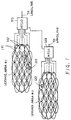
- Figure 1 is a diagram illustrating a cellular radio telephone system. A
service area # 1 is covered by a plurality ofcells 101. Abase station 102 is provided for eachcell 101. Mobile telephone switching offices (MTSO)103, 123 are provided for eachservice area # 1, #2 and connected to a plurality ofbase stations 102 and a landline.Mobile units base station 102 of thecell 101 within which the mobile unit is located. - In the conventional system, a mobile identification number (MID) is provided for a mobile unit in a service area. Therefore a user uses only one MID in the service area and has to communicate with another party by way of only one MID regardless of public usage or private usage.
- If we assume that a company is registered as the user, the company has to pay a user fee for not only public use but also private use of the MID.
- Further, in operation of some cellular mobile systems (for example "AMPS" in the United States of America), there is a service in which a party has to pay a user fee.
- In this system, therefore, the user may have to pay a user fee for an unwanted incoming call.
- The present invention therefore seeks to provide novel radio telecommunication apparatus having a plurality of MIDs.
- The present invention also seeks to provide a novel telecommunication apparatus that enables the user to select an MID from a plurality of different MIDs in the apparatus and to receive only a predetermined incoming call, so that it is possible for the user to use the apparatus for public use or for private use.
- The present invention also seeks to provide an improved radio telecommunication apparatus that enables the user to divide a charge between user fee for public use and for private use.
- Accordingly a first aspect of the invention provides a radio telecommunication apparatus which stores a plurality of MIDs, and when a user selects at least one of the stored MIDs and the apparatus receives an MID transmitted from a base unit, the received MID is compared to each of the selected MIDs. When the user does not select any one of the stored MID, the apparatus informs a user that the user should input an instruction information necessary for selecting at least one of the stored MIDs. When the received MID coincides with one of the selected MID, the apparatus is enabled to communicate with the base unit.
- According to another aspect of the invention, an apparatus stores a plurality of MIDs and when a user selects one of the stored MIDs and inputs a call origination request, the selected MID is sent to a base unit. When the user does not select any one of the stored MIDs and inputs a call origination request, the apparatus informs a user that the user should input an instruction information necessary for selecting one of the stored MIDs.
-
- FIG.1 is a block diagram illustrating a cellular radio telephone system ;
- FIG.2 is a block diagram illustrating a cellular radio telephone system of the present invention ;
- FIG.3 is a block diagram illustrating an . arrangement of a mobile telephone apparatus according to an embodiment of the present invention ;
- FIG.4 is a block diagram of
radio unit 300 shown in FIG.3 ; - FIG.5 is a chart illustrating the content of
ID ROM 370 shown in FIGs.3 and 4 ; - FIG.6 is a chart illustrating the content of
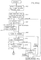
RAM 335 shown in FIG.4 ; - FIG.7 is a flow chart illustrating a process for selecting an MID, for receiving an incoming call, from MIDs stored in
ID ROM 370 ; - FIG.8 is a flow chart illustrating a process for selecting an MID, for performing a call origination, from MIDs stored in
ID ROM 370 ; - FIG.9 is a flow chart illustrating a connection control operation sequence in the cellular telephone system of the present invention ;
- FIG.10 is a flow chart illustrating a reset operation step in the connection control operation of FIG.9 ;
- FIG.11 is a flow chart illustrating an intialization. operation step in the connection control operation of FIG.9 ;
- FIG.12 is a flow chart illustrating an operation after the intialization operation in the connection control operation of FIG.9 ;
- FIG.13 is a flow chart illustrating an incoming call response operation in the connection control operation of FIG.9 ;
- FIGs.14(a),14(b) show a flow chart illustrating a call origination operation in the connection control operation of FIG.9 ;
- FIG.15 is a block diagram illustrating an arrangement of a mobile telephone apparatus according to another embodiment of the present invention ;
- FIG.16 is a chart illustrating the content of a RAM used in the embodiment illustrated in FIG.15 ;
- FIG.17 is a flow chart illustrating a process for selecting an MID for receiving a facsimile signal from MIDs stored in
ID ROM 370 ; and - FIGs.18(a),18(b) show a flow chart illustrating an incoming call response operation of another embodiment.
- A preferred embodiment of the present invention applied in a mobile telephone will be described with reference to the accompanying drawings.
- Referring to FIG.2, a
mobile unit 140 is located within acell 151 including abase station 152.Mobile unit 140 includes a mobile telephone apparatus. Three mobile identification numbers MID 1-3 which are identification numbers for the mobile telephone apparatus, are stored with a serial number SER.100 in anID ROM 370 of the mobile telephone apparatus. These MIDs 1-3 are also registerd in MTSO 153. - FIG.3 is a block diagram showing an arrangement of the
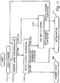
mobile telephone apparatus 200 according to an embodiment of the present invention. Referring to FIG.3,mobile telephone apparatus 200 comprises anantenna 202, aradio unit 300 and atelephone unit 400.Antenna 200 is mounted on an outer body surface of an automobile.Telephone unit 400 is mounted near the driver's seat inside the automobile. -
Radio unit 300 includes aradio section 310 for establishingradio channels 315 with a base station (not shown) throughantenna 202 and for exchanging signals therewith, aradio unit controller 330 for controlling the overall operations of the apparatus, avoice synthesizer 350 for synthesizing voices,ID ROM 370 for storing MID 1-3 with the serial number and apower source 390 for supplying power from the battery mounted in the automobile to the above components throughfuse 317. -
Telephone unit 400 includes ahandset controller 418 for controlling the overall operations oftelephone unit 400 in response to instructions or the like fromradio unit controller 330, a key unit 430 for entering key inputs, adisplay unit 450 for displaying numerical or alphabetical characters in response to control signals fromhandset controller 418,switches 470 including a hook switch and a power switch, and selectable audio input/output units 490a and 490b for inputting or outputting an audible sound.Telephone unit 400 may be divided intomain unit 400a andhandset 400b. Amicrophone 494 may be a hands-free microphone mounted on a sun visor or the like near the driver's seat and is connected tomain unit 400a. Loudspeaker 492 may be mounted inmain unit 400a. Loudspeaker 492 and microphone 494 constitute audio input/output unit 490a ofmain unit 400a.Handset controller 418, key unit 430, anddisplay unit 450 are mounted inhandset 400b. Ahandset microphone 466 and ahandset receiver 498 constitute audio input/output unit 490b ofhandset 400b. - Each section of
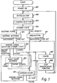
radio unit 300,main unit 400a andhandset 400b is supplied power by way of apower line 505 extending frompower source 390 inradio unit 300. The opened or closed status ofswitches 470 is transmitted topower source 390 orradio unit controller 330 by way of aline 500 or aline 501, respectively. Control and/or command signals are transmitted betweenhandset controller 418 andradio unit controller 330 by way oflines 502. Audio signals are transmitted by way oflines 503.Radio unit controller 330 sends control signals to audio input/output unit 490a, 490b by way oflines 504. - FIG.4 is a block diagram showing a detailed arrangement of
radio unit 300 of FIG.3. Referring to FIG.4,radio section 310 comprises a demodulator 312, a modulator 314 and asynthesizer 320. Demodulator 312 demodulates a radio signal received from the base station throughradio channels 315,antenna 202 andduplexer 318. It should be noted that this radio signal includes audible sound signals and control signals. Modulator 314 modulates the audio and control signals received from anaudio circuit 337 and generates the required transmission signals. - Power amplifier 316 amplifies the transmission signals received from modulator 314. The amplification by power amplifier 316 may be continuous or variable in a step-wise fashion,e.g.,8-step variable.
Duplexer 318 sends the signals received throughradio channel 315 to demodulator 312 and the signals from modulator 314 and power amplifier 316 toantenna 202.Synthesizer 320 includes a channel selection local oscillator and specifies a frequency from which signals are demodulated by demodulator 312 and a frequency to which signals are modulated by modulator 314. About 666 channels are available fromsynthesizer 320. -
Radio unit controller 330 includes a central processing unit (CPU) 331, an oscillator/frequency divider 332, anaddress decoder 333, aROM 334, aRAM 335, aradio controller 336,audio circuit 337, acontrol signal processor 338, anaudio circuit controller 339, adigital interface 340, apower controller 341 and an interruptcontroller 342.Reference numerals CPU 331 controls the operation ofradio unit controller 330. Oscillator/frequency divider 332 supplies clock signals toCPU 331 and divides the clock signals to supply appropriate frequency-divided pulses as timing pulses to each section of the mobile telephone apparatus requiring them.Addres decoder 333 outputs predetermined operation signals to the components in response to instruction singals fromCPD 331.ROM 334 stores various programs required for operation ofCPD 331.RAM 335 stores various types of data during processing for use byCPU 331.Radio controller 336controls radio section 310 in response to instructions fromCPU 331. For example,radio controller 336 sends signals indicative of available frequencies tosynthesizer 320, signals indicative of an amplification level to power amplifier 316, and signals indicative of modulation parameters to modulator 314.Radio controller 336 receives a step-out signal fromsynthesizer 320 and output power detection signals from power amplifier 316 and forwards these singals toCPU 331, thereby preventing operational errors. -
Audio circuit 337 extracts control singals and audio signals from the received signals demodulated by demodulator 312 and supplies the control signals to controlsignal processor 338 and the audio signals totelephone unit 400.Audio circuit 337 also supplies a control signal fromcontrol signal processor 338 and audio signals fromtelephone unit 400 to modulator 314. - It should be noted that
audio circuit 337 also arranges the waveform of the control signal to be sent to controlsignal processor 338 in a particular signal format and filters the control signal to be supplied to modulator 314.Control signal processor 338 performs bit and frame synchronization with the control signal fromaudio circuit 337. Maintaining the required synchronization,control signal processor 338 converts the serial control signals, including control data received from a base station, into parallel signals and converts the parallel control data signals to be transmitted to a base station into serial signals. The control signals are sent to and from the base station viaaudio circuit 337. -
Audio circuit controller 339 controlsaudio circuit 337. Under the control ofaudio circuit controller 339, for example,audio circuit 337 applies the received signals from demodulator 312 to controlsignal processor 338 ortelephone unit 400 and selectively receives the signals fromcontrol signal processor 338 ortelephone unit 400.Digital interface 340 interfaces the data communication betweenradio unit 300 andtelephone unit 400.Power controller 341controls power source 390 and sets a voltage supplied from a battery 506 topower source 390 to a predetermined level. The voltage having the predetermined level is supplied to the respective circuit components. - Fig.5 is a diagram which illustrates the contents of
ID ROM 370 shown in FIGs. 3 and 4. In this embodiment, three mobile identification numbers MID1-3, which are identification numbers for the mobile telephone, are stored with the serial number SER. No.100 at predetermined addresses inID ROM 370, i.e., FF00-FF20. The serial number is provided for the mobile telephone apparatus in the cellular system. Further a priority flag corresponding to MID1 is at logic "1" and priority flags corresponding to MID2,3 are at logic "0". - Fig.6 is a diagram which illustrates the content of
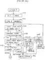
RAM 335.RAM 335 has an area which is called Number Assignment Module NAM hereinafter. NAM1 is an area where specified MID1-3 are stored. The apparatus is permitted to receive an incoming signal having one of these MIDs in NAM1. On the other hand, NAM2 is an area where only one specified MID3 is stored. The apparatus is permitted to perform call origination to another party by way of this specified MID3 in NAM2. - Fig.7 is a flow chart which shows a process for storing at least one of MID1-3 for receiving an incoming call signal into NAM1. TO determine if the user wishes to designate one or more MIDs for receiving an incoming call signal, for example, "FCN", "#", "8", "0" key operations of the handset are checked (step 601). If these keys are operated, a beep sound is generated (step 603). Thereafter, in order to urge the user to input an instruction necessary for selecting at least one MID, a specific information is displayed to the user. The displayed information is "Which MID do you use for receiving incoming call signal? Input any key. "0"...all MID,"1"... MID1, "2"... MID2, "3"... MID3" (step 604). After this operation, " 0" key operation is checked (step 605). When "0" key is operated, all MID1-3 into ID-
ROM 370 are stored into NAM1 (step 606). When "1" key is operated, MID1 is stored into NAM1 (step 607, step 608). When "2" key is operated, MID2 is stored into NAM1 (step 609, step 610). When "3" key is operated, MID3 is stored into NAM1 (step 611, step 612). If none of "0","1","2","3" keys are operated, none of the MIDs is stored into NAM1. - After one of the MIDs is stored into NAM1, a specific information is displayed. The displayed information is "If you wish to use another MID for receiving incoming call signal, input any key."(step 613). Thereafter if any key is operated during a predetermined period of time, MID corresponding to the operated key is stored into NAM1. If no key is operated during the predetermined period of time, a designated incoming call mode flag is set at logic "1" (step 614). When all MIDs are stored into NAM1 (step 606), the designated incoming call mode flag is set at logic "1" (step 614).
- Fig.8 is a flow chart which shows a process for storing one of MID1-3 for performing a call origination into NAM2. To determine if the user wishes to designate one MID for performing a call origination, for example, "FCN","#","7","0" key operations are checked (step 701). When these operations are checked, a beep sound is generated (step 703). Thereafter, in order to urge the user to input an instruction necessary for selecting an MID for performing a call origination , a specific information is displayed to the user. The displayed information is "Which MID do you use for performing call origination? Input any key. "1".--MID1, "2"---MID2, "3"---MID3''(step 704). After this operation, when "1" key is operated, MID1 is stored into NAM2 (
step 705,step 706). When "2" key is operated, MID2 is stored into NAM2 (step 707,step 708). When "3" key is operated, MID3 is stored into NAM2 (step 709,step 710). If none of "1","2","3" keys are operated, none of MIDs is stored into NAM2. When any one of the MIDs is stored into NAM2, a designated call origination mode flag is set at logic "1" (step 714). - A connection control operation of
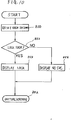
mobile telephone apparatus 200 will now be described with reference to FIG.9. When a power switch of the mobile telephone apparatus is turned on, a reset operation starts (step 801). This operation is illustrated with reference to FIG.10. - In response to turning on a power switch,
CPU 331 resets each section (step 850). After that, a condition of whether the apparatus is allowed to be used or not, is checked. This check is defined as a lock state check (step 852). As long as the lock state is not cancelled, another party is not allowed to operate the apparatus. In this state, "Lock" is displayed on the display 450 (step 854). In the event that the apparatus is not set to be "Lock" state, "NO SVC" is displayed (step 856). "NO SVC" means that a communication service has not been started during the reset operation. After the reset operation, an initialization starts (step 802). - FIG. 11 is a detailed flow chart which illustrates the initial radio channel connection operation after the power supply is turned on. In response to a control signal from
CPU 331,radio controller 336 inradio unit controller 330 controls synthesizer 320 to change the frequency of output therefrom. Thereby, a predetermined range of control channels (referred to as D channels hereinafter) are scanned in demodulator 312 to obtain the information indicative of electric field intensity of the received signals over each channel (step 901). The channel having the strongest electric field intensity is selected from the D channels and the apparatus is ready for receiving signals through the D channel having the strongest electric field intensity. In this case, information of a channel having the second strongest intensity is also obtained. - Under the control of
CPU 331,audio circuit controller 339 controlsaudio circuit 337 so that the output of demodulator 312 is applied to the input ofcontrol signal processor 338 and the output ofcontrol signal processor 338 is applied to the input of modulator 314. -
Control signal processor 338 performs bit and frame synchronization operations on signals received through the selected D channel (step 903). Thereby, a communication link is established between the mobile telephone and a base station. System information is then detected from signals received through this D channel by control signal processor 338 (step 905) and sent toCPU 331. The system information includes a system identification number (referred to as SID hereinafter) and a range of frequency channels (referred to as P channels hereinafter) to be scanned next. The received SID represents an MTSO covering the area where the mobile telephone is located.CPD 331 stores the SID in an SID register ofRAM 335. - If the word synchronization or system information reception is not performed within a predetermined period of time, the D channel having the second strongest intensity is used to repeat the above operation (step 907). In this case, if word synchronization or system information reception is again not performed within the predetermined period of time, the demodulator scans the D channels again (step 901).
- When the above initialization operations are completed, scanning similar to the above scanning operation is performed for the P channels for receiving an incoming signal (
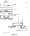
step 803 in FIG. 9). - FIG. 12 is a detailed flow chart which illustrates the P channel connection after initialization. Responsive to a control signal from
CPD 331,radio controller 336 controls synthesizer 320 to change the frequency of the output therefrom so that P channels are scanned in demodulator 312 (step 1001) to obtain the information indicative of the electric field intensity of the received signals. The apparatus is ready for receiving information through the P channel having the strongest electric field intensity. In this case, information indicative of the P channel having the second strongest intensity is also obtained. -
Control signal processor 338 performs bit and frame synchronization operations on signals received through the P channel which has the strongest electric field intensity (step 1003). After acquiring synchronization,control signal processor 338 obtains system information, including an SID representing an MTSO for serving the mobile telephone, from the following information signals (step 1005) and sends it toCPU 331. - If the word synchronization or system information reception or system information reception is not performed within a predetemined period of time, an operation similar to the one described above is performed for the P channel having the second strongest intensity (step 1007). In this case, when word synchronization or system information reception is again not performed within the predetermined period of time, initialization is resumed (
step 802 of FIG.9). If position information is not obtained from system information, initialization is also resumed (step 802 of FIG.9). The above connection control operations set the apparatus to the receive standby mode (step 804 of FIG.9). - In the standby state in
step 804 of FIG.9, if the apparatus receives an incoming signal, an incoming response sequence is performed (step 805). The incoming response sequence is illustrated by FIG.13. -
CPU 331 detects an incoming call signal through the P channel (step 1101). The incoming call signal includes an MID. In this case, the designated incoming call mode flag is checked (step 1103). When the designated incoming call mode flag is logic "1", the received MID is compared with the MID stored in NAM1 (step 1105). If the received MID coincides with ,i.e.,matches, one of the MID stored in NAM1, theCPU 331 causes the demodulator to scan each predetermined control channel (defined as A channel) to obtain information indicative of the strongest electric field intensity (step 1109). In this case, information indicative of second strongest electric field intensity is also obtained. If the received MID does not coincide with any one of the MID stored in NAM1, initialization is resumed (step 802 of FIG.9). When the designated incoming call mode flag is logic "0", the received MID is compared with the MIDs stored in ID ROM 370 (step 1107). If the received MID coincides with one of the MIDs stored inID ROM 370, scanning of A channel is performed (step 1109). In this case, if the received MID does not coincide with any one of the MIDs stored inID ROM 370, initialization is resumed (step 802). - Next, a word synchronization is performed on signals received through the selected A channel (step 1111). If the word synchronization is performed within a predetermined period of time, a system information is detected by signals received through this A channel (step 1113). If the word synchronization is not performed or the system information is not obtained within a predetermined period of time, the A channel having the second strongest intensity is used to repeat the above operation (step 1115). In this case, if word synchronization is again not performed or system reception is again not performed within a predetermined period of time, initialization is resumed (
step 802 of Fig.9) - After the system information is obtained, a receive acknowledge signal is sent through the selected A channel to the base station (step 1117). The receive acknowledge signal includes the matched MID and the serial number. When the base station receives the receive acknowledge signal, the base station compares the matched MID and the serial number with the registered MID and serial number as referred to in Fig. 2. If they coincide with each other and, therefore the matched MID corresponds to the registered serial number, the base station sends a signal including information indicative of designated speech channels.
- If the signal is received during a predetermined period of time by the apparatus (step 1119), A channels are switched to the designated speech channels which include a forward channel for transmitting audio signals to the base station and a backward channel for receiving audio signals from the calling apparatus (step 1121). Thereby a communication link between a calling telephone appaiatus and the called apparatus is established. If the matched MID and the serial number do not coincide with the registered MID and serial number in the base station and, therefore the matched MID does not correspond to the registered serial number, the base station does not send the signal including the information indicative of designated speech channels. If the
CPU 331 does not detect a signal during a predetermined period of time (step 1119), initilization is resumed (step 802 of Fig. 9). - The apparatus is set to be in a standby state for receiving a ringing signal (
step 806 in Fig. 9). When a ringing signal is received, the apparatus generates a ringing tone. In this state, the apparatus is set to be awaiting user's response (step 809). - When the user responds to the ringing tone by depressing the "SEND" key,
handset controller 418 detects the key operation and sends a control signal of "SEND" key operation toCPU 331 viadigital interface 340 by way oflines 502. Also in the event that the user takeshandset 400b off-hook, information indicating the closed state of the hook switch in switch 470 (Fig 3) is transmitted toCPU 331 viadigital interface 340 by way ofline 501. Responsive to the off-hook control signal or the information,CPU 331 sends a connection signal toaudio circuit controller 339. Receiving the connection signal,audio circuit controller 339 controlsaudio circuit 337 so that demodulator 312 and modulator 314 are connected to one of audio input/output unit 490a and 490b by way ofline 503. Accordingly, the user may communicate with the calling party by using hands-free microphone 494 andloudspeaker 492 orhandset microphone 466 andhandset receiver 498. When the electric field intensity of speech channels is less than a predetermined level because of a fading during more than a a predetermined period of time in the acknowledge signal sending state (step 1117), or the speech channel reception state (step 1119), or a communication enable state (step 1121), or user's response awaiting state (step 809 of Fig. 9), the transmission function is disabled (step 808 of Fig. 9). During communication, when the user takes the handset on-hook, the communication through speech channels is ceased (step 807). Thereafter when the transmission function is disabled (step 808), initialization is resumed (step 802). - Next, a call origination processing sequence will be described. FIGs.14(a),14(b) show a detailed flow chart showing outgoing call processing. In the standby state in
step 804 of FIG.9, when a callrequest is detected by an input at the key unit 430, a timer for counting a call reception time is set (step 1201). The set time is, e.g., 12 seconds. - Thereafter, the audio controller in the radio unit causes the demodulator to scan each predetermined control channel (step 1202) to obtain reception electric field intensity information. The channel having the strongest electric field intensity is selected from these control channels and the apparatus is set to receive signals through the control channel having the strongest intensity. In this case, information indicative of the control channel having the second strongest electric field intensity is also obtained.
- Next, the presence of the user wishing to make a call is checked (step 1203). This check is performed as follows. If the user enters a telephone number to be called on key pad 430 and depresses the "SEND" key, these key inputs are detected by
handset controller 418.Handset controller 418 sends a detection signal toCPU 331 inradio unit controller 330. Responsive to the detection signal, a call flag inCPU 331 is set at a logic "1". In this case, the apparatus determines that the user wishes to make a call. However, if the user depresses the "END" key after depression of the "SEND" key, the call flag is reset at a logic "0". In this case, the apparatus determines that the user does not wish to make a call and initialization is resumed (step 802 of FIG.9). -
Control signal processor 338 performs bit and frame synchronization operations of the currently received control channel. That is, word synchronization thereof is performed to obtain system information from this control channel. However, if word synchronization cannot be performed, the same operation is performed using the control channel having the second strongest intensity (step 1205). In this case, if no word synchronization can be performed, initialization is resumed (step 802 of FIG.9). - And then, the apparatus confirms again whether the user wishes to make a call (step 1206). As described above, if the call flag is set at logic "1", the apparatus determines that the user wishes to make a call. However, if the call flag is set at logic "0", the apparatus determines that the user does not wish to make a call and initialization is resumed (
step 802 of FIG.9). -
CPU 331 confirms whether the selected control channel is appropriate for the origination signal to be broadcast by analyzing the system information signal from a base station. Upon the selection of an appropriate control channel(step 1207), a channel selection flag inCPU 331 is changed from logic "0" to "1". However, if any appropriate control channel is not selected, initialization is resumed (step 802 of FIG.9) without changing the content of the channel selection flag. If the selection of an appropriate control channel is delayed (step 1208), the apparatus checks again whether the user wishes to make a call (step 1206). - In FIG.14(b), when a designated call origination mode flag is set at a logic "1" (step 1210), the presence of an MID in NAM2 is checked(step 1212). When an MID is stored in NAM2, the MID in NAM2 is adopted(step 1213).
- When the designated call origination mode flag is set at a logic "0" (step 1210), In order to urge the user to select one of MID 1-3 stored in
ID ROM 370, a specific information is displayed to the user(step 1214). The displsyed information is "rich MID do you use for performing call origination? Input any key. "1"...MID1, "2"---MID2, "3".-.MID3". If a key corresponding to one of the MIDs is operated,CPU 331 adopts the MID intoID ROM 370 corresponding to the key operation (step 1216). If no key operation is performed,CPU 331 adopts the MID stored inID ROM 370 having a predetermined priority by checking a priority flag in ID ROM 370 (step 1218). As noted in FIG.5, the priority flag of MID1 is set at a logic "1", therefore, MID1 is adopted. When an MID is not stored in NAM2 (step 1212), initialization is resumed (step 802 of FIG.9). - After an MID is adopted, a call origination signal is sent through the control channel (step 1220). The call origination signal includes the adopted MID, the serial number and an identification number of an appratus to be called entered by the user.
- When the base station receives the acknowledge signal, the base station compares the received MID and serial number with the registerd MID and serial number. If they coincide with each other, the base station sends an acknowledge signal to the apparatus. If they do not coincide with each other, the base station does not send the acknowledge signal to the apparatus. Thereafter, the mobile telephone apparatus detects whether the acknowledge signal from the base station has been received (step 1222). The base station calls the other party to be called on the basis of the ID number included in the call origination signal. A communication link may then be established between the mobile telephone apparatus and the called telephone apparatus (step 1224). Otherwise, initialization is resumed (
step 802 of FIG.9). Thus, a communication link can be established as mentioned above (step 810 of FIG.9), and thereafter the communication is closed. Key input in step 1216 may be replaced by a voice. The voice is detected byvoice synthesizer 350 shown in FIG.3. - Although the information for urging the user to select MID is displayed, the
voice synthesizer 350 shown in FIG.3 may generate a voice coresponding to the information . - As has been described in the incoming call reception sequence, when the received MID coincides with one of the MID stored in NAM1, the communication link is established. Therefore the apparatus receives predetermined incoming call. The user is able to use the apparatus for public use in a case, for example during a weekday, for private use in another case, for example during a holiday.
- Further in the call origination processing sequence when an MID is stored in NAM2, the communication link is established by way of the selected MID stored in NAM2. Therefore the user is able to pay a user fee distinguishing first user fee for public use from a second user fee for private use.
- FIG.15 is a flow chart showing another embodiment.
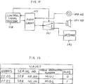
Audio circuit 337 is connected to themicrophones switch 391. Theswitch 391 is connected to thespeakers facsimile 393. Thefacsimile 393 includes a CPU, a memory, a detecting portion for detecting a ringing signal, and a recording portion not shown. Theswitch 391 is controlled by thecontrol signal processor 338. - FIG.16 shows a diagram which illustrates the content of NAM1. Two MID1,2 are stored with a serial number:SER NO.100 at predetermined adresses FF00,FF01. MID1 is stored for a telephone ID number. MID2 is stored for a facsimile ID number. Therefore the flag corresponding to MID1 is set at logic "0". The flag corresponding to
MID 2 is set at logic "1". - Fig.17 is a flow chart which shows a process for storing at least one of MID1-3 for receiving a facsimile signal into NAM1. To determine if the user wishes to designate one MID for receiving a facsimile signal, for example, "FCN","#","6","0" key operations are checked (step 1301). If these keys are operated, a beep sound is generated (step 1303). Thereafter, MID stored in NAM1 is displayed (step 1305). Thereafter, in order to urge the user to input an instruction necessary for selecting MID, a specific information is displayed. The displayed information is "Which MID do you use for receiving facsimile signal? Input any key. "1"...MID1, "2"...MID2, "3"... MID3" (step 1307). After this operation, when "1" key is operated, MID1 is stored into NAM1 (
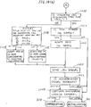
step 1309, step 1311). When "2" key is operated, MID2 is stored into NAM1 (step 1313, step 1315). When "3" key is operated, MID3 is stored into NAM1 (step 1317, step 1319). If none of "1","2","3" keys are not operated, none of the MIDs is stored into NAM1. When any one of the MIDs is stored into NAM1, a flag corresponding to the stored MID for receiving a facsimile signal is set at logic "1" (step 1320). A flag corresponding to the stored MID for an incoming telephone call signal is set at logic "0". In FIG.16, MID2 is the MID for receiving a facsimile signal, therefore the flag corresponding to MID2 is set at logic "1". On the other hand, MID1 is the MID for an incoming telephone call signal, therefore the flag corresponding to MID1 is set at logic "0". - FIGs.18(a), 18(b) show a flow chart showing a process for receiving a facsimile signal. The apparatus receives the incoming call signal (step 1501). If the received MID does not coincide with any one of the stored MIDs in NAM1, initialization is resumed (
step 802 of FIG.9). If the received MID coincides with one of the stored MIDs in NAM1 (step 1503), the flag of NAM1 is checked (step 1505). If the flag corresponding to the matched MID in NAM1 is set at logic "1", the control signal processor provides a control signal with theswitch 391. According to this signal, theaudio circuit 337 is connected to the facsimile 393 (step 1507). Otherwise, the control signal processor does not provide a control signal with theswitch 391. - Thereafter, a sequence from
step 1509 to step 1521 similar to the described sequence fromstep 1109 to step 1121 in FIG.13 is performed. - In the standby state (step 1523), when the received MID coincides with the designated MID for a telephone (step 1524), the described sequence from
step 809 in FIG.9 is performed. When the received MID coincides with the designated MID for a facsimile, the ringing signal is detected (step 1525) and a well-known facsimile sequence is performed. Therefore it is possible for the user to designate an MID for a facsimile number or a telephone number. - In this embodiment, the control signal processor determines whether the received MID coincides with the designated number for the facsimile or the telephone number. According to the result, the control signal processor connects
audio circuit 337 tofacsimile 393. On the other hand, a conventional apparatus does not have this feature. Therefore in the conventional apparatus, after the user takes a handset off-hook when an incoming call for the facsimile is received, the user listens to sound accompanied with a facsimile sequence. According to the sound, the user needs to operate a manual switch for connecting the audio circuit to the facsimile. In contract, according to the above describrd embodiment, the user does not need to operate the switch for connecting the audio circuit to the facsimile. Further, if the user sets the facsimile so that the facsimile does not generate a ringing tone, the user does not need to take the handset off-hook when an incoming call for the facsimile is received. Therefore the user does not need to listen to a sound accompanied with the facsimile sequence. - In FIG.15, a facsimile device may be provided as another terminal device. Although an embodiment applied to a mobile telephone apparatus has been described, it will now be apparent to those skilled in this art that this invention may be easily applied to any kind of radio telecommunication apparatus, for example, to a portable type radio telephone. This invention also is applicable to a dual mode apparatus adopting one of the digital modulating system or the analog modulating system. Further, the concepts of the present invention may be applied to a data transmission apparatus used in a cellular radio telecommunication system.
Claims (13)
- Radio telecommunication apparatus for use in a radio telecommunication system, wherein the radio telecommunication system encompasses a plurality of areas each having at least one base unit (152) which broadcasts a mobile identification number over at least one radio channel within the area of the base unit (152), characterized in that the radio telecommunication apparatus includes:
means (370) for storing a plurality of mobile identification numbers;
input means (430,466,494) for optional manual selection of at least one of the stored mobile identification numbers;
receiving means (310) for receiving a broadcast mobile identification number ("MID");
comparing means (330) for comparing the received mobile identification number with each of the selected mobile identification numbers, if a manual selection has been made, or with all of the stored mobile identification numbers if a manual selection has not been made; and
link enabling means (310) responsive to the comparing means (330) for establishing a communication link with the base unit (152) only if the result of the comparison is positive. - Apparatus according to claim 1, characterized in that the enabling means (310) includes means (310) for enabling access to a radio channel.
- Apparatus according to claim 1 or claim 2, characterized in that a serial number for the apparatus is stored in the storing means (370), and the link enabling means (310) further comprises means for sending the serial number and a mobile identification number which coincides with the received mobile identification number.
- Apparatus according to any preceding claim, characterized in that the apparatus includes second storing means (335) responsive to the input means (430) for storing the selected mobile identification number or numbers.
- Radio telecommunication apparatus for use in a radio telecommunication system, wherein the radio telecommunication system encompasses a plurality of areas each having at least one base unit (152) which broadcasts a mobile identification number over at least one radio channel within the area of the base unit (152), characterized in that the radio telecommunication apparatus includes:
means (370) for storing a plurality of mobile identification numbers;
input means (430,466,494) for optional manual selection of a stored mobile identification number and for entering a call origination request and address information of a party to be called; and
means (310) responsive to the input means (430,466,494) for sending the selected mobile identification number and the input address information if a manual selection has been made. - Apparatus according to claim 5 in which the sending means sends a mobile identification number having a predetermined priority stored in the storing means 370) and the input address information if no manual selection has been made.
- Apparatus according to claim 5 or claim 6, characterized in that a serial number for the apparatus is stored in the storing means (370) and the sending means (310) also sends the serial number for the apparatus.
- Apparatus according to any of claims 5 to 7, characterized in that the apparatus includes audible or visible alerting means (450,350) responsive to the input means (430,466,494) for informing the user that a manual selection should be made.
- Radio telecommunication apparatus having a telephone device (400) and a terminal device (393), the apparatus being used in a radio telecommunication system, wherein the radio telecommunication system encompasses a plurality of areas each having at least one base unit (152) which broadcasts a mobile identification number over at least one radio channel within the area of the base unit (152), characterised in that the radio telecommunication apparatus includes:
means (370) for storing a plurality of mobile identification numbers;
means (420,466,494) for designating a first mobile identification number stored in the storing means (370) as a mobile identification number for the telephone device (400) and for designating a second mobile identification number store in the storing means (370) as a mobile identification number for the terminal device (393);
means (310) coupled to the telephone device (400) for receiving a mobile identification number from the base unit (152);
comparing means (4330) responsive to the receiving means (310) and the designating means (430,466,494) for comparing the received mobile identification number with each of the designated mobile identification numbers; and
coupling means (391) responsive to the comparing means (330) for coupling the receiving means (310) to the terminal device (393) if the received mobile identification number coincides with the mobile identification number for the terminal device (393). - Apparatus according to claim 9, characterized in that the terminal device (393) is a facsimile device (393).
- A method of enabling a radio telecommunication apparatus to be used in a radio telecommunication system, wherein the radio telecommunication system encompasses a plurality of areas each having at least one base unit (152) which broadcasts a mobile identification number over at least one radio channel within the area of the base unit (152), characterized in that the method includes the steps of:
storing a plurality of mobile identification numbers;
making a manual selection of at least one of the stored mobile identification numbers;
receiving a mobile identification number;
comparing the received mobile identification number with the or each of the selected mobile identification numbers; and
establishing a communication link with the base unit (152) only if the received mobile identification number coincides with one of the selected mobile identification numbers. - A method of enabling radio telecommunication apparatus to be used in a radio telecommunication system, wherein the radio telecommunication system encompasses a plurality of areas each having at least one base unit (152) which broadcasts a mobile identification number over at least one radio channel within the area of the base unit (152), characterized in that the method includes the steps of:
entering a manual selection of one of the stored mobile identification numbers;
entering a call origination request and address information of a party to be called; and
sending the selected mobile identification number and the input address information. - A method according to claim 12 further comprising the steps of alerting the user to enter the required manual selection; and utilising a default value of the mobile identification number if the user fails to make the required selection.
Priority Applications (2)
| Application Number | Priority Date | Filing Date | Title |
|---|---|---|---|
| EP97202679A EP0825792A3 (en) | 1992-01-29 | 1993-01-28 | Method of enabling radio telecommunication apparatus to be used in a radio telecommunication system |
| EP05076374A EP1585353A3 (en) | 1992-01-29 | 1993-01-28 | Method of enabling radio telecommunication apparatus to be used in a radio telecommunication system |
Applications Claiming Priority (6)
| Application Number | Priority Date | Filing Date | Title |
|---|---|---|---|
| JP1429492 | 1992-01-29 | ||
| JP1429492 | 1992-01-29 | ||
| JP14294/92 | 1992-01-29 | ||
| JP77981/92 | 1992-03-31 | ||
| JP4077981A JPH05284103A (en) | 1992-03-31 | 1992-03-31 | Radio telephone system |
| JP7798192 | 1992-03-31 |
Related Child Applications (4)
| Application Number | Title | Priority Date | Filing Date |
|---|---|---|---|
| EP97202679A Division EP0825792A3 (en) | 1992-01-29 | 1993-01-28 | Method of enabling radio telecommunication apparatus to be used in a radio telecommunication system |
| EP05076374A Division EP1585353A3 (en) | 1992-01-29 | 1993-01-28 | Method of enabling radio telecommunication apparatus to be used in a radio telecommunication system |
| EP97202679.3 Division-Into | 1997-09-01 | ||
| EP05076374.7 Division-Into | 2005-06-13 |
Publications (3)
| Publication Number | Publication Date |
|---|---|
| EP0554093A2 true EP0554093A2 (en) | 1993-08-04 |
| EP0554093A3 EP0554093A3 (en) | 1993-11-18 |
| EP0554093B1 EP0554093B1 (en) | 2005-09-14 |
Family
ID=26350219
Family Applications (3)
| Application Number | Title | Priority Date | Filing Date |
|---|---|---|---|
| EP97202679A Withdrawn EP0825792A3 (en) | 1992-01-29 | 1993-01-28 | Method of enabling radio telecommunication apparatus to be used in a radio telecommunication system |
| EP93300639A Expired - Lifetime EP0554093B1 (en) | 1992-01-29 | 1993-01-28 | Radio telecommunication apparatus |
| EP05076374A Withdrawn EP1585353A3 (en) | 1992-01-29 | 1993-01-28 | Method of enabling radio telecommunication apparatus to be used in a radio telecommunication system |
Family Applications Before (1)
| Application Number | Title | Priority Date | Filing Date |
|---|---|---|---|
| EP97202679A Withdrawn EP0825792A3 (en) | 1992-01-29 | 1993-01-28 | Method of enabling radio telecommunication apparatus to be used in a radio telecommunication system |
Family Applications After (1)
| Application Number | Title | Priority Date | Filing Date |
|---|---|---|---|
| EP05076374A Withdrawn EP1585353A3 (en) | 1992-01-29 | 1993-01-28 | Method of enabling radio telecommunication apparatus to be used in a radio telecommunication system |
Country Status (5)
| Country | Link |
|---|---|
| US (1) | US5437053A (en) |
| EP (3) | EP0825792A3 (en) |
| KR (1) | KR960016879B1 (en) |
| CA (1) | CA2088299C (en) |
| DE (1) | DE69333868D1 (en) |
Cited By (6)
| Publication number | Priority date | Publication date | Assignee | Title |
|---|---|---|---|---|
| EP0650307A2 (en) * | 1993-10-26 | 1995-04-26 | Kabushiki Kaisha Toshiba | Radio telecommunication apparatus |
| EP0720403A2 (en) * | 1994-12-28 | 1996-07-03 | Ntt Mobile Communications Network Inc. | Mobile communication system, automatic call receiving method, and mobile station |
| WO1998000992A2 (en) * | 1996-06-28 | 1998-01-08 | Harris Corporation | Improvements in or relating to a method and apparatus for determining symbol timing in a wireless communications system, also using a reusable control channel, and reducing power |
| US5943325A (en) * | 1996-06-28 | 1999-08-24 | Ctp Systems, Ltd. | Method and apparatus for determining symbol timing in a wireless communications system |
| US6023460A (en) * | 1996-06-28 | 2000-02-08 | Harris Corporation | Wireless communications system and method using a reusable control channel |
| WO2011036186A1 (en) * | 2009-09-23 | 2011-03-31 | St-Ericsson (France) Sas | Process for updating location information |
Families Citing this family (33)
| Publication number | Priority date | Publication date | Assignee | Title |
|---|---|---|---|---|
| NL9301492A (en) * | 1993-08-31 | 1995-03-16 | Nederland Ptt | System for mobile communication in overlapping communication domains. |
| US5590397A (en) * | 1993-12-17 | 1996-12-31 | Nec Corporation | Selecting and prioritizing radio telephone systems at radio terminal |
| DE4402903A1 (en) * | 1994-02-02 | 1995-08-03 | Deutsche Telekom Mobil | Method for packet-wise data transmission in a mobile radio network |
| JPH07264657A (en) * | 1994-03-18 | 1995-10-13 | Toshiba Corp | Mobile radio communication device |
| JPH089042A (en) * | 1994-06-24 | 1996-01-12 | Matsushita Electric Ind Co Ltd | Radio telephone system |
| JP3301222B2 (en) * | 1994-06-28 | 2002-07-15 | ソニー株式会社 | Portable telephone device |
| EP0690645B1 (en) * | 1994-06-30 | 2006-08-02 | Casio Computer Co., Ltd. | Radio communication apparatus having a plurality of identification codes |
| US5764730A (en) * | 1994-10-05 | 1998-06-09 | Motorola | Radiotelephone having a plurality of subscriber identities and method for operating the same |
| IL112926A (en) * | 1995-03-07 | 2000-07-16 | Geotek Communications Inc | Subscriber unit for use in a multiple access communication system |
| US5781612A (en) * | 1995-03-10 | 1998-07-14 | Northern Telecom Limited | Radio terminal interfaces for voice and data telecommunications, and methods for their operation |
| US5613201A (en) * | 1995-07-25 | 1997-03-18 | Uniden America Corporation | Automatic call destination/system selection in a radio communication system |
| EP0767562B1 (en) * | 1995-09-11 | 2006-05-17 | Kabushiki Kaisha Toshiba | Method and apparatus for communication control |
| US5713072A (en) * | 1995-09-12 | 1998-01-27 | Marth; Charles | Cellular fraud deterrent system |
| US5963863A (en) * | 1995-12-01 | 1999-10-05 | Telefonaktiebolaget L M Ericsson | Routing system for automatically routing a call to a multi-mode transceiver in a wireless network |
| US6253074B1 (en) | 1996-01-10 | 2001-06-26 | Telefonaktiebolaget L/M Ericsson (Publ) | Cellular telecommunications systems having selectively associatable usage parameters |
| US5878348A (en) * | 1996-05-30 | 1999-03-02 | Telefonaktiebolaget Lm Ericsson (Publ) | System and method for implementing multiple home location registers for a single mobile station in a cellular telecommunications network |
| US5983095A (en) * | 1996-07-26 | 1999-11-09 | Telefonaktiebolaget Lm Ericsson (Publ) | System and method of calling a single mobile telephone through multiple directory numbers in a radio telecommunications network |
| JPH1051349A (en) * | 1996-08-01 | 1998-02-20 | Nec Corp | Portable communication equipment |
| US5918172A (en) * | 1996-09-27 | 1999-06-29 | Highwaymaster Communications, Inc. | Multiple number assignment module communication |
| US6026291A (en) * | 1997-04-09 | 2000-02-15 | Telefonaktiebolaget L M Ericsson | Cellular system having programmable subscription capabilities |
| US6311063B1 (en) * | 1997-12-10 | 2001-10-30 | Mci Communications Corporation | Method of and system for emulation of multiple subscriber profiles on a single mobile phone in a wireless telecommunications network |
| FI107689B (en) * | 1998-04-03 | 2001-09-14 | Nokia Networks Oy | A method for establishing a signaling connection |
| US6308060B2 (en) * | 1998-06-15 | 2001-10-23 | @Track Communications, Inc. | Method and apparatus for providing a communication path using a paging network |
| US6405033B1 (en) | 1998-07-29 | 2002-06-11 | Track Communications, Inc. | System and method for routing a call using a communications network |
| US6167255A (en) * | 1998-07-29 | 2000-12-26 | @Track Communications, Inc. | System and method for providing menu data using a communication network |
| US6535743B1 (en) | 1998-07-29 | 2003-03-18 | Minorplanet Systems Usa, Inc. | System and method for providing directions using a communication network |
| US20020137505A1 (en) * | 2000-02-18 | 2002-09-26 | Eiche Steven A. | Audio detection for hands-free wireless |
| US6745040B2 (en) | 2001-06-25 | 2004-06-01 | Koninklijke Philips Electronics N.V. | Method and system for processing incoming calls on a communication unit |
| KR101145159B1 (en) * | 2005-01-04 | 2012-05-16 | 인텔렉츄얼 벤처스 원 엘엘씨 | A method to prevent alternating mobile node identity in borders between domains in a wireless network |
| US8477731B2 (en) * | 2005-07-25 | 2013-07-02 | Qualcomm Incorporated | Method and apparatus for locating a wireless local area network in a wide area network |
| US8483704B2 (en) * | 2005-07-25 | 2013-07-09 | Qualcomm Incorporated | Method and apparatus for maintaining a fingerprint for a wireless network |
| US9123189B2 (en) * | 2007-02-12 | 2015-09-01 | The Boeing Company | System and method for point-of-use instruction |
| US20100159920A1 (en) * | 2008-12-24 | 2010-06-24 | Hsin-Chang Wu | System for monitoring radiation intensity of electromagnetic wave of a mobile phone |
Citations (6)
| Publication number | Priority date | Publication date | Assignee | Title |
|---|---|---|---|---|
| GB2172775A (en) * | 1985-03-19 | 1986-09-24 | Oki Electric Ind Co Ltd | Cellular radio telephone system |
| EP0332825A2 (en) * | 1988-03-18 | 1989-09-20 | Motorola, Inc. | Cellular data telephone and method for communicating data |
| EP0344989A2 (en) * | 1988-05-30 | 1989-12-06 | Kabushiki Kaisha Toshiba | Radio telecommunication apparatus |
| WO1991001067A2 (en) * | 1989-07-12 | 1991-01-24 | Motorola, Inc. | Method for authentication and protection of subscribers in telecommunication systems |
| EP0435052A2 (en) * | 1989-12-26 | 1991-07-03 | Motorola, Inc. | Automatic new system registration notification |
| EP0526981A2 (en) * | 1991-07-08 | 1993-02-10 | Nokia Mobile Phones Ltd. | Cellular telephone with plural telephone numbers |
Family Cites Families (7)
| Publication number | Priority date | Publication date | Assignee | Title |
|---|---|---|---|---|
| FR2474334A1 (en) | 1980-01-28 | 1981-07-31 | Lafarge Sa | MIXING DEVICE WITH TURBULENCE OF GASEOUS FLUIDS |
| US4578540A (en) * | 1982-12-20 | 1986-03-25 | At&T Bell Laboratories | Telecommunications systems |
| US4677653A (en) * | 1986-06-16 | 1987-06-30 | B/W Investments | Cellular mobile phone with a plurality of accessing telephone numbers for allowing access to the mobile phone by any one of the telephone numbers |
| US4734928A (en) * | 1986-06-16 | 1988-03-29 | B/W Investments | Cellular mobile phone with a plurality of accessing telephone numbers for allowing access to the mobile phones by any one of the telephones numbers |
| US5029233A (en) * | 1987-10-09 | 1991-07-02 | Motorola, Inc. | Radio arrangement having two radios sharing circuitry |
| US5220681A (en) * | 1989-02-27 | 1993-06-15 | Multi-Leasing Services Inc. | Electronic signal decoder display/enunciator apparatus for electronic signal receivers |
| US4972355A (en) * | 1989-10-02 | 1990-11-20 | Motorola, Inc. | Method for radiotelephone autonomous registration |
-
1993
- 1993-01-28 CA CA002088299A patent/CA2088299C/en not_active Expired - Lifetime
- 1993-01-28 EP EP97202679A patent/EP0825792A3/en not_active Withdrawn
- 1993-01-28 EP EP93300639A patent/EP0554093B1/en not_active Expired - Lifetime
- 1993-01-28 EP EP05076374A patent/EP1585353A3/en not_active Withdrawn
- 1993-01-28 DE DE69333868T patent/DE69333868D1/en not_active Expired - Lifetime
- 1993-01-28 US US08/010,199 patent/US5437053A/en not_active Expired - Lifetime
- 1993-01-29 KR KR1019930001115A patent/KR960016879B1/en not_active IP Right Cessation
Patent Citations (6)
| Publication number | Priority date | Publication date | Assignee | Title |
|---|---|---|---|---|
| GB2172775A (en) * | 1985-03-19 | 1986-09-24 | Oki Electric Ind Co Ltd | Cellular radio telephone system |
| EP0332825A2 (en) * | 1988-03-18 | 1989-09-20 | Motorola, Inc. | Cellular data telephone and method for communicating data |
| EP0344989A2 (en) * | 1988-05-30 | 1989-12-06 | Kabushiki Kaisha Toshiba | Radio telecommunication apparatus |
| WO1991001067A2 (en) * | 1989-07-12 | 1991-01-24 | Motorola, Inc. | Method for authentication and protection of subscribers in telecommunication systems |
| EP0435052A2 (en) * | 1989-12-26 | 1991-07-03 | Motorola, Inc. | Automatic new system registration notification |
| EP0526981A2 (en) * | 1991-07-08 | 1993-02-10 | Nokia Mobile Phones Ltd. | Cellular telephone with plural telephone numbers |
Cited By (10)
| Publication number | Priority date | Publication date | Assignee | Title |
|---|---|---|---|---|
| EP0650307A2 (en) * | 1993-10-26 | 1995-04-26 | Kabushiki Kaisha Toshiba | Radio telecommunication apparatus |
| EP0650307A3 (en) * | 1993-10-26 | 1995-11-29 | Toshiba Kk | Radio telecommunication apparatus. |
| EP0720403A2 (en) * | 1994-12-28 | 1996-07-03 | Ntt Mobile Communications Network Inc. | Mobile communication system, automatic call receiving method, and mobile station |
| EP0720403A3 (en) * | 1994-12-28 | 1999-09-29 | Ntt Mobile Communications Network Inc. | Mobile communication system, automatic call receiving method, and mobile station |
| WO1998000992A2 (en) * | 1996-06-28 | 1998-01-08 | Harris Corporation | Improvements in or relating to a method and apparatus for determining symbol timing in a wireless communications system, also using a reusable control channel, and reducing power |
| WO1998000992A3 (en) * | 1996-06-28 | 1998-06-25 | Harris Corp | Improvements in or relating to a method and apparatus for determining symbol timing in a wireless communications system, also using a reusable control channel, and reducing power |
| US5943325A (en) * | 1996-06-28 | 1999-08-24 | Ctp Systems, Ltd. | Method and apparatus for determining symbol timing in a wireless communications system |
| US6023460A (en) * | 1996-06-28 | 2000-02-08 | Harris Corporation | Wireless communications system and method using a reusable control channel |
| WO2011036186A1 (en) * | 2009-09-23 | 2011-03-31 | St-Ericsson (France) Sas | Process for updating location information |
| US8725155B2 (en) | 2009-09-23 | 2014-05-13 | St-Ericsson Sa | Process for updating location information |
Also Published As
| Publication number | Publication date |
|---|---|
| US5437053A (en) | 1995-07-25 |
| EP0825792A3 (en) | 1998-05-27 |
| EP0554093B1 (en) | 2005-09-14 |
| CA2088299C (en) | 1997-12-23 |
| DE69333868D1 (en) | 2005-10-20 |
| CA2088299A1 (en) | 1993-07-30 |
| EP0554093A3 (en) | 1993-11-18 |
| KR930017322A (en) | 1993-08-30 |
| KR960016879B1 (en) | 1996-12-23 |
| EP0825792A2 (en) | 1998-02-25 |
| EP1585353A2 (en) | 2005-10-12 |
| EP1585353A3 (en) | 2012-01-25 |
Similar Documents
| Publication | Publication Date | Title |
|---|---|---|
| EP0554093B1 (en) | Radio telecommunication apparatus | |
| US5101500A (en) | Radio telecommunication apparatus | |
| US5109401A (en) | Radio telecommunication apparatus capable of controlling call charges | |
| JP2528001B2 (en) | How to make and receive calls on a cellular cordless phone | |
| US5570413A (en) | Cellular telephone and associated method for opening a voice channel with a source telephone without establishing voice communications therewith | |
| US6108543A (en) | Radio communication apparatus connected with a base station used in a service area prior to the others | |
| US5602900A (en) | Radio Telecommunication apparatus | |
| CA2080709C (en) | Radio telecommunication apparatus using system identification number | |
| US5471643A (en) | Radio telecommunication apparatus | |
| US6006107A (en) | Radio telecommunication apparatus and method having stored system identification numbers | |
| JPH05284103A (en) | Radio telephone system | |
| EP0650307B1 (en) | Radio telecommunication apparatus | |
| EP0438137B1 (en) | Radio telecommunication apparatus | |
| JP3224886B2 (en) | Wireless communication device | |
| JP2809641B2 (en) | Mobile station equipment | |
| JP3056869B2 (en) | Mobile radio communication device | |
| JP2854579B2 (en) | Mobile station equipment | |
| JPH01259635A (en) | Mobile station device | |
| JPH09187064A (en) | Mobile station device | |
| KR100241779B1 (en) | Meet-me service access method in a ct-2 terminal | |
| KR19990056213A (en) | How to send phone number of mobile phone | |
| KR19980016364A (en) | Multi-call processing method of mobile communication terminal | |
| JPH05130028A (en) | Mobile radio communication system and its mobile station equipment | |
| JPH0555998A (en) | Mobile body communication terminal equipment for mobile body communication system | |
| JPH0548528A (en) | Ratio telephone system |
Legal Events
| Date | Code | Title | Description |
|---|---|---|---|
| PUAI | Public reference made under article 153(3) epc to a published international application that has entered the european phase |
Free format text: ORIGINAL CODE: 0009012 |
|
| 17P | Request for examination filed |
Effective date: 19930212 |
|
| AK | Designated contracting states |
Kind code of ref document: A2 Designated state(s): DE FR GB SE |
|
| PUAL | Search report despatched |
Free format text: ORIGINAL CODE: 0009013 |
|
| AK | Designated contracting states |
Kind code of ref document: A3 Designated state(s): DE FR GB SE |
|
| 17Q | First examination report despatched |
Effective date: 19961209 |
|
| GRAP | Despatch of communication of intention to grant a patent |
Free format text: ORIGINAL CODE: EPIDOSNIGR1 |
|
| GRAS | Grant fee paid |
Free format text: ORIGINAL CODE: EPIDOSNIGR3 |
|
| GRAA | (expected) grant |
Free format text: ORIGINAL CODE: 0009210 |
|
| RIC1 | Information provided on ipc code assigned before grant |
Ipc: 7H 04B 7/26 B Ipc: 7H 04Q 7/38 A |
|
| AK | Designated contracting states |
Kind code of ref document: B1 Designated state(s): DE FR GB SE |
|
| REG | Reference to a national code |
Ref country code: GB Ref legal event code: FG4D |
|
| XX | Miscellaneous (additional remarks) |
Free format text: TEILANMELDUNG 97202679.3 EINGEREICHT AM 01/09/97. |
|
| REF | Corresponds to: |
Ref document number: 69333868 Country of ref document: DE Date of ref document: 20051020 Kind code of ref document: P |
|
| PG25 | Lapsed in a contracting state [announced via postgrant information from national office to epo] |
Ref country code: SE Free format text: LAPSE BECAUSE OF FAILURE TO SUBMIT A TRANSLATION OF THE DESCRIPTION OR TO PAY THE FEE WITHIN THE PRESCRIBED TIME-LIMIT Effective date: 20051214 |
|
| PG25 | Lapsed in a contracting state [announced via postgrant information from national office to epo] |
Ref country code: DE Free format text: LAPSE BECAUSE OF FAILURE TO SUBMIT A TRANSLATION OF THE DESCRIPTION OR TO PAY THE FEE WITHIN THE PRESCRIBED TIME-LIMIT Effective date: 20051215 |
|
| PGFP | Annual fee paid to national office [announced via postgrant information from national office to epo] |
Ref country code: FR Payment date: 20060110 Year of fee payment: 14 |
|
| PGFP | Annual fee paid to national office [announced via postgrant information from national office to epo] |
Ref country code: DE Payment date: 20060126 Year of fee payment: 14 |
|
| PLBE | No opposition filed within time limit |
Free format text: ORIGINAL CODE: 0009261 |
|
| STAA | Information on the status of an ep patent application or granted ep patent |
Free format text: STATUS: NO OPPOSITION FILED WITHIN TIME LIMIT |
|
| 26N | No opposition filed |
Effective date: 20060615 |
|
| PG25 | Lapsed in a contracting state [announced via postgrant information from national office to epo] |
Ref country code: FR Free format text: LAPSE BECAUSE OF FAILURE TO SUBMIT A TRANSLATION OF THE DESCRIPTION OR TO PAY THE FEE WITHIN THE PRESCRIBED TIME-LIMIT Effective date: 20061020 |
|
| EN | Fr: translation not filed | ||
| EN | Fr: translation not filed | ||
| REG | Reference to a national code |
Ref country code: GB Ref legal event code: 732E Free format text: REGISTERED BETWEEN 20110113 AND 20110119 |
|
| REG | Reference to a national code |
Ref country code: GB Ref legal event code: 732E Free format text: REGISTERED BETWEEN 20110428 AND 20110504 |
|
| PGFP | Annual fee paid to national office [announced via postgrant information from national office to epo] |
Ref country code: GB Payment date: 20120125 Year of fee payment: 20 |
|
| REG | Reference to a national code |
Ref country code: GB Ref legal event code: PE20 Expiry date: 20130127 |
|
| PG25 | Lapsed in a contracting state [announced via postgrant information from national office to epo] |
Ref country code: GB Free format text: LAPSE BECAUSE OF EXPIRATION OF PROTECTION Effective date: 20130127 |