EP0553699A1 - Apparatus for testing the ends of cigarettes - Google Patents
Apparatus for testing the ends of cigarettes Download PDFInfo
- Publication number
- EP0553699A1 EP0553699A1 EP93100773A EP93100773A EP0553699A1 EP 0553699 A1 EP0553699 A1 EP 0553699A1 EP 93100773 A EP93100773 A EP 93100773A EP 93100773 A EP93100773 A EP 93100773A EP 0553699 A1 EP0553699 A1 EP 0553699A1
- Authority
- EP
- European Patent Office
- Prior art keywords
- test
- photoelectric
- light
- cigarette
- test device
- Prior art date
- Legal status (The legal status is an assumption and is not a legal conclusion. Google has not performed a legal analysis and makes no representation as to the accuracy of the status listed.)
- Ceased
Links
Images


Classifications
-
- A—HUMAN NECESSITIES
- A24—TOBACCO; CIGARS; CIGARETTES; SIMULATED SMOKING DEVICES; SMOKERS' REQUISITES
- A24C—MACHINES FOR MAKING CIGARS OR CIGARETTES
- A24C5/00—Making cigarettes; Making tipping materials for, or attaching filters or mouthpieces to, cigars or cigarettes
- A24C5/32—Separating, ordering, counting or examining cigarettes; Regulating the feeding of tobacco according to rod or cigarette condition
- A24C5/34—Examining cigarettes or the rod, e.g. for regulating the feeding of tobacco; Removing defective cigarettes
- A24C5/3412—Examining cigarettes or the rod, e.g. for regulating the feeding of tobacco; Removing defective cigarettes by means of light, radiation or electrostatic fields
Definitions
- the invention relates to a test arrangement for testing the ends of cigarettes, in particular for detecting ends which are insufficiently filled with tobacco, with a conveyor for conveying the cigarettes past a first test station for the tobacco quantities in the cigarette ends.
- the object on which the invention is based is to provide a further development of test arrangements of the aforementioned type.
- the solution according to the invention is characterized by at least one further test station for detecting the tobacco quantities in the ends of the cigarettes conveyed on the conveyor.
- An advantageous development of the invention is an embodiment of the first test station as a photoelectric test device for the cigarette ends. According to the invention, this can have at least one light-emitting light source emitting the cigarette ends and at least one light through the cigarette tubes in the end regions.
- the first test device can have at least one light source designed as an infrared diode, which is assigned an optical system for parallelizing the emitted light.
- An optical filter that filters out light outside the infrared range can be assigned to the photoelectric receiver having at least one infrared-sensitive photodiode.
- Several photoelectric receivers can be arranged at a distance from one another, which detect the light passing through the cigarette tubes in different sectors of the end regions; To suppress extraneous light, the photoelectric receivers designed as photodiodes can be arranged in the channels delimiting the interrogation angle.
- the further test station can have a capacitive test device.
- the latter has a capacitor arranged in a high-frequency resonant circuit, preferably a stray field capacitor, the stray field of which penetrates the cigarette ends, a measuring arrangement being provided for an electrical value dependent on the amount of tobacco in the cigarette ends.
- the further test station can have a photoelectric test device.
- the photoelectric test device can have at least one light emitting light emitting onto the cigarette ends and at least one light depending on the nature of the cigarette ends-detecting photoelectric receiver.
- the light source can be designed as a laser.
- the photoelectric receiver can detect the light reflected from the cut surface of the cigarettes.
- the light emitted by a light source can be directed to the cigarette ends and / or the light can be returned from the cigarette ends to a receiver.
- the cigarette ends are in a defined position in relation to the test device, in particular in the further test station, at the time of the test. According to the invention, this can be ensured by a positioning arrangement which brings the cigarette ends into defined positions with respect to a test device at the time of the test.
- a measuring device for detecting the distances between the cigarette ends and the testing device can also be provided, the distance-dependent measuring signal of which is taken into account when testing the cigarette ends becomes.
- the advantage associated with the invention is that tobacco incompletely filled areas in the end area of the cigarettes (defects) which have not been detected by a test device are detected and displayed by the further test device, which preferably works by a different method.
- the invention also relates to a test device for testing the ends of cigarettes, in particular for detecting ends which are insufficiently filled with tobacco, with a conveyor for conveying the cigarettes through a photoelectric test station with at least one light source emitting light on the cigarette ends and with at least one light through the Cigarette case in the head end area detecting photoelectric receiver.
- the object on which the invention is based is to provide a further development of test devices of the aforementioned type.
- the solution of the object according to the invention is that the light source is designed as an infrared diode, which is assigned an optical system for parallelizing the emitted light.
- an infrared diode light-emitting diode
- optics which makes the test largely independent of distance fluctuations between the cigarette ends and the light source.
- An advantageous development of the invention consists in providing a photodiode, preferably an infrared-sensitive photodiode, as a photoelectric receiver, which is preceded by a filter which at least largely filters out light with a wavelength in the visible range.
- the test device is at least largely independent of extraneous light.
- a further advantageous embodiment of the invention can be achieved if a plurality of photoelectric receivers are provided at a distance from one another which detect the light passing through the cigarette tubes in different zones of the head end region.
- the detection areas of the several photoelectric receivers are advantageously arranged symmetrically on the circumference of the cigarette ends. Badly filled ends can then be reliably grasped, even if the tobacco is distributed asymmetrically in them as desired.
- the photodiodes in channels, e.g. B. holes.
- Another advantageous embodiment of the invention consists in arranging at least one translucent cover in front of the photoelectric receivers.
- Such covers e.g. B. made of glass, protect the optical and photoelectric elements from soiling caused by dust emerging from the cigarette ends, tobacco crumbs and the like.
- the security of capturing e.g. B. asymmetrically filled cigarette ends can also be improved according to the invention in that the photoelectric receivers are connected in parallel in such a way that the output signal of a receiver triggers an error signal when a threshold value is exceeded.
- a significant improvement in the test result can be achieved if the photoelectric test device according to the invention is combined with a further test device which capacitively detects the tobacco quantities in the cigarette ends.
- the cigarettes to be tested are conveyed in succession past both test devices, it being irrelevant which test signal is generated first because the test is non-contact in both cases.
- a defective cigarette end that is not recognized by one (eg photoelectric) test method is most likely detected by the other (eg capacitive) test method and vice versa.
- other suitable measuring methods e.g. photoelectric
- photoelectric can also be combined in further measuring devices.
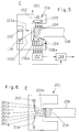
- the photoelectric test device 1 forms the essential part of the photoelectric test station B. It has a bright light source which preferably consists of a diode 2 (light emitting diode) emitting light in the infrared (IR) range.
- An optical system 3 is arranged in the beam path of the emitted IR light, which parallelises the light. Between the optics 3 and the end 4 of a cigarette 6 to be scanned for sufficient tobacco filling, there is a translucent cover in the form of a glass plate 7, which mechanically separates the light-emitting part of the photoelectric test device from the cigarette end 4 and thereby prevents dirt or sticky tobacco crumbs get the sensitive optics 3.
- the cigarette 6 is conveyed in receptacles 8 of a rotating test drum 9 known per se and therefore not shown in detail through the test area of the test device 1, wherein it is held in the receptacles 8 by suction air in channels 11.
- the test drum 9 is provided with a plurality of receptacles 8 in which the cigarettes to be tested are conveyed successively through the photoelectric test station B.
- the end region 4 of the cigarette 6 can be more or less filled with tobacco.
- FIG. 2 shows a very poor filling, in which a number of tobacco particles 12 are missing.
- the infrared light emitted by the light-emitting diode 2 and parallelized by the optics 3 and coming into the interior 13 of the cigarette end 4 is transmitted to the outside with a component in the direction of the arrows 14, 15, 16 and 20 deflected (only arrows 14 and 16 visible in FIG. 2) and thus illuminates the inside of the cigarette paper 17 which acts as a wrapper in the end region 4 of a cigarette 6.
- a cigarette 6 is advantageously detected by several photoelectric receivers, preferably photodiodes 18, 19, 21 and 22, which are distributed symmetrically on the circumference and are arranged in channels in the form of bores 23, 24, 26 and 27.
- the number of diodes and channels can of course be larger or smaller.
- the holes prevent extraneous light from falsifying the test results.
- Optical infrared filters 28, 29, 31 and 32 serve the same purpose, ensuring that only IR light can reach the photodiodes.
- the four photodiodes each capture a sector 6a, 6b, 6c and 6d of the circumference of the cigarette end 4. It can be advantageous here that the scanned sectors overlap somewhat.
- the outputs of the photodiodes 18, 19, 21 and 22 are connected to inputs of a threshold element 33 which responds as soon as even one photodiode indicates by its output signal that the peripheral sector of the cigarette end 4 which it has detected is illuminated, which indicates that as a result missing tobacco, part of the IR light emitted by the light-emitting diode 2 can reach the cigarette paper 17 in the end area and illuminate it. If there is a lack of as much tobacco as indicated in FIG. 2, then all photodiodes can emit output signals which can be attributed to an insufficient tobacco content in the cigarette end 4.
- a particularly advantageous development of the invention consists of placing a further capacitive test station C upstream or downstream of the photoelectric test station B.
- An arrangement is shown in FIG. 1, in which the path of the cigarette 6 to a capacitive testing device 34 known per se is marked by a dash-dotted line 36.
- Insufficiently filled cigarette ends, which for some reason have not been detected by the photoelectric test device 1, are at least partially detected by the capacitive test device 34 or vice versa. This increases the security of the detection of such insufficiently filled ends considerably.
- FIGS. 3 and 4 show details of the capacitive end test device 34.
- the capacitive measuring arrangement 34 with an annular electrode 457 and an electrode 458 arranged concentrically thereto forms the end of a stationary sliding surface 501, which is a positioning device for the cigarette ends 406 with respect to the measuring electrodes 457 and 458.
- a stationary sliding surface 501 which is a positioning device for the cigarette ends 406 with respect to the measuring electrodes 457 and 458.
- the measuring arrangement 34 has a high-frequency voltage source 459b which supplies the electrodes 457 and 458, which are frequency-determining part of a known electrical resonance circuit 462, with high-frequency voltage of constant frequency stabilized by a quartz crystal.
- An insufficient filling of the cigarette ends 404 i.e. Output signals from the optical test device 1 and the capacitive test device 34 which indicate too little tobacco can be used in a manner known per se to separate out the corresponding cigarettes, for which purpose a known electrically controlled blown air valve can be used.
- FIG. 5 shows a variant, designated 101, of the further test station C.
- the corresponding photoelectric test device 101 has a light source 102, which is advantageously designed as a laser.
- the light beam 102a emanating from the laser reaches the cut surface 104a in the end region 104 of the cigarette 106.
- the reflected part 102b of the light beam reaches a photoelectric receiver 118, e.g. B. a photodiode, which emits an electrical signal dependent on the amount of tobacco in the end region 104.
- the cigarettes to be checked for their ends are successively moved past the photoelectric test device 101 on a conveyor. If it cannot be ensured (e.g. by means of a positioning arrangement corresponding to 501 in FIG.
- a measuring device 151 can be provided for detecting the distance be.
- the measuring device can have a light source 152 and an optic 153 for parallelizing the light on one side of the end region.
- an array 154 of individual photodiodes 156a ... e (which are of course much more in reality) can be provided.
- the number of exposed or vice versa of the unexposed diodes is then a measure of the distance between the cut surfaces 104a and the laser 102.
- the number corresponding to the distance can be determined in a conventional evaluation arrangement 157.
- the electrical signal corresponding to the distance value can be calculated in a computing stage 158 with the output signal of the photoelectric receiver 118 in such a way that the influence of distance fluctuations is eliminated.
- FIG. 6 shows a variant 201 of the photoelectric test device in the further test station C, in which the light coming from a light source 202 is guided in optical fibers 261a ... d to the cut surface 204a of the cigarettes 206.
- the reflected light is guided to the photoelectric receiver 218 via optical fibers 261e ... g. 5 and 6 are defined in a manner known per se by control elements which are synchronized with the conveyor of the cigarettes and then emit corresponding control signals when the cigarettes are in the test position.
- test devices at stations B and C which operate according to photoelectric, capacitive or other known measuring methods.
Landscapes
- Health & Medical Sciences (AREA)
- General Health & Medical Sciences (AREA)
- Toxicology (AREA)
- Manufacturing Of Cigar And Cigarette Tobacco (AREA)
- Investigating Or Analysing Materials By Optical Means (AREA)
Abstract
Description
Die Erfindung betrifft eine Prüfanordnung zum Prüfen der Enden von Zigaretten, insbesondere zum Erfassen von unzureichend mit Tabak gefüllten Enden, mit einem Förderer zum Fördern der Zigaretten vorbei an einer ersten Prüfstation für die Tabakmengen in den Zigarettenenden.
Die der Erfindung zugrundeliegende Aufgabe besteht darin, eine Weiterbildung von Prüfanordnungen der vorerwähnten Art zu schaffen.
Die Lösung gemäß der Erfindung ist gekennzeichnet durch mindestens eine weitere Prüfstation zum Erfassen der Tabakmengen in den Enden der auf dem Förderer geförderten Zigaretten.
Eine vorteilhafte Weiterbildung der Erfindung ist eine Ausbildung der ersten Prüfstation als fotoelektrische Prüfvorrichtung für die Zigarettenenden. Diese kann erfindungsgemäß mindestens eine Licht auf die Zigarettenenden strahlende Lichtquelle und mindestens einen Licht durch die Zigarettenhüllen in den Endenbereichen erfassenden fotoelektrischen Empfänger aufweisen. Dabei kann die erste Prüfvorrichtung mindestens eine als Infrarotdiode ausgebildete Lichtquelle aufweisen, der eine Optik zum Parallelisieren des abgegebenen Lichtes zugeordnet ist. Dem mindestens eine infrarotempfindliche Fotodiode aufweisenden fotoelektrischen Empfänger kann ein Licht außerhalb des Infrarotbereichs ausfilternder optischer Filter zugeordnet sein. Mehrere fotoelektrische Empfänger können im Abstand voneinander angeordnet sein, die das in unterschiedlichen Sektoren der Endenbereiche durch die Zigarettenhüllen tretende Licht erfassen; zum Ausblenden von Fremdlicht können die als Fotodioden ausgebildeten fotoelektrischen Empfänger in den Abfragewinkel begrenzenden Kanälen angeordnet sein.The invention relates to a test arrangement for testing the ends of cigarettes, in particular for detecting ends which are insufficiently filled with tobacco, with a conveyor for conveying the cigarettes past a first test station for the tobacco quantities in the cigarette ends.
The object on which the invention is based is to provide a further development of test arrangements of the aforementioned type.
The solution according to the invention is characterized by at least one further test station for detecting the tobacco quantities in the ends of the cigarettes conveyed on the conveyor.
An advantageous development of the invention is an embodiment of the first test station as a photoelectric test device for the cigarette ends. According to the invention, this can have at least one light-emitting light source emitting the cigarette ends and at least one light through the cigarette tubes in the end regions. In this case, the first test device can have at least one light source designed as an infrared diode, which is assigned an optical system for parallelizing the emitted light. An optical filter that filters out light outside the infrared range can be assigned to the photoelectric receiver having at least one infrared-sensitive photodiode. Several photoelectric receivers can be arranged at a distance from one another, which detect the light passing through the cigarette tubes in different sectors of the end regions; To suppress extraneous light, the photoelectric receivers designed as photodiodes can be arranged in the channels delimiting the interrogation angle.
Die weitere Prüfstation kann gemäß der Erfindung eine kapazitiv arbeitende Prüfvorrichtung aufweisen. Letztere weist in vorteilhafter weiterer Ausgestaltung der Erfindung einen in einem Hochfrequenz-Schwingkreis angeordneten Kondensator, vorzugsweise einen Streufeldkondensator auf, dessen Streufeld die Zigarettenenden durchsetzt, wobei eine Meßanordnung für einen von der Menge des Tabaks in den Zigarettenenden abhängigen elektrischen Wert vorgesehen ist.
Die weitere Prüfstation kann gemäß einer weiteren Ausbildung der Erfindung eine fotoelektrische Prüfvorrichtung aufweisen. Dabei kann die fotoelektrische Prüfvorrichtung mindestens eine Licht auf die Zigarettenenden strahlende Lichtquelle und mindestens einen Licht in Abhängigkeit von der Beschaffenheit der Zigarettenenden erfassenden fotoelektrischen Empfänger aufweisen. Die Lichtquelle kann gemäß der Erfindung als Laser ausgebildet sein. Der fotoelektrische Empfänger kann das von der Schnittfläche der Zigaretten reflektierte Licht erfassen. Die Aufleitung des von einer Lichtquelle abgegebenen Lichtes auf die Zigarettenenden und/oder die Rückleitung des Lichtes von den Zigarettenenden zu einem Empfänger kann gemäß der Erfindung über Lichtleitfasern erfolgen.
Für die Genauigkeit der Prüfung von Zigarettenenden kann es vorteilhaft sein, wenn die Zigarettenenden sich im Prüfzeitpunkt in einer definierten Lage zu der Prüfvorrichtung, insbesondere in der weiteren Prüfstation, befinden. Gemäß der Erfindung kann dafür eine Positionierungsanordnung sorgen, die die Zigarettenenden im Prüfzeitpunkt in definierte Lagen bezüglich einer Prüfvorrichtung verbringt. Anstelle einer Positionierungsanordnung kann auch eine Meßvorrichtung zum Erfassen der Abstände zwischen den Zigarettenenden und der Prüfvorrichtung vorgesehen sein, deren abstandsabhängiges Meßsignal bei der Prüfung der Zigarettenenden berücksichtigt wird.According to the invention, the further test station can have a capacitive test device. In an advantageous further embodiment of the invention, the latter has a capacitor arranged in a high-frequency resonant circuit, preferably a stray field capacitor, the stray field of which penetrates the cigarette ends, a measuring arrangement being provided for an electrical value dependent on the amount of tobacco in the cigarette ends.
According to a further embodiment of the invention, the further test station can have a photoelectric test device. The photoelectric test device can have at least one light emitting light emitting onto the cigarette ends and at least one light depending on the nature of the cigarette ends-detecting photoelectric receiver. According to the invention, the light source can be designed as a laser. The photoelectric receiver can detect the light reflected from the cut surface of the cigarettes. According to the invention, the light emitted by a light source can be directed to the cigarette ends and / or the light can be returned from the cigarette ends to a receiver.
For the accuracy of the testing of cigarette ends, it can be advantageous if the cigarette ends are in a defined position in relation to the test device, in particular in the further test station, at the time of the test. According to the invention, this can be ensured by a positioning arrangement which brings the cigarette ends into defined positions with respect to a test device at the time of the test. Instead of a positioning arrangement, a measuring device for detecting the distances between the cigarette ends and the testing device can also be provided, the distance-dependent measuring signal of which is taken into account when testing the cigarette ends becomes.
Der mit der Erfindung verbundene Vorteil besteht darin, daß mit Tabak unzureichend gefüllte Stellen im Endenbereich der Zigaretten (Fehlstellen), die von einer Prüfvorrichtung nicht erfaßt worden sind, von der vorzugsweise nach einem anderen Verfahren arbeitenden weiteren Prüfvorrichtung erfaßt und angezeigt werden.The advantage associated with the invention is that tobacco incompletely filled areas in the end area of the cigarettes (defects) which have not been detected by a test device are detected and displayed by the further test device, which preferably works by a different method.
Die Erfindung betrifft außerdem eine Prüfvorrichtung zum Prüfen der Enden von Zigaretten, insbesondere zum Erfassen von unzureichend mit Tabak gefüllten Enden, mit einem Förderer zum Fördern der Zigaretten durch eine fotoelektrische Prüfstation mit mindestens einer Licht auf die Zigarettenenden strahlenden Lichtquelle und mit mindestens einem Licht durch die Zigarettenhülle im Kopfendenbereich erfassenden fotoelektrischen Empfänger.The invention also relates to a test device for testing the ends of cigarettes, in particular for detecting ends which are insufficiently filled with tobacco, with a conveyor for conveying the cigarettes through a photoelectric test station with at least one light source emitting light on the cigarette ends and with at least one light through the Cigarette case in the head end area detecting photoelectric receiver.
Die der Erfindung zugrundeliegende Aufgabe besteht darin, eine Weiterbildung von Prüfvorrichtungen der vorerwähnten Art vorzusehen.The object on which the invention is based is to provide a further development of test devices of the aforementioned type.
Die Lösung der Aufgabe gemäß der Erfindung besteht darin, daß die Lichtquelle als Infrarotdiode ausgebildet ist, der eine Optik zum Parallelisieren des abgegebenen Lichtes zugeordnet ist.The solution of the object according to the invention is that the light source is designed as an infrared diode, which is assigned an optical system for parallelizing the emitted light.
Die Verwendung einer Infrarotdiode (Leuchtdiode) als Lichtquelle läßt eine relativ hohe Lichtleistung zu; das von einer fast punktförmigen Lichtquelle ausgesandte Licht wird vorteilhaft durch eine Optik parallelisiert, wodurch die Prüfung weitgehend unabhängig von Abstandsschwankungen zwischen Zigarettenenden und Lichtquelle wird.The use of an infrared diode (light-emitting diode) as a light source allows a relatively high light output; the light emitted by an almost punctiform light source is advantageously parallelized by optics, which makes the test largely independent of distance fluctuations between the cigarette ends and the light source.
Eine vorteilhafte Weiterbildung der Erfindung besteht darin, eine Fotodiode, vorzugsweise eine infrarotempfindliche Fotodiode als fotoelektrischen Empfänger vorzusehen, der ein Filter vorgeschaltet ist, welcher Licht mit einer Wellenlänge im sichtbaren Bereich zumindest weitgehend ausfiltert.
Hierdurch wird die Prüfvorrichtung zumindest weitgehend unabhängig von Fremdlicht.
Eine weitere vorteilhafte Ausgestaltung der Erfindung ist erreichbar, wenn mehrere fotoelektrische Empfänger im Abstand voneinander vorgesehen sind, die das in unterschiedlichen Zonen des Kopfendenbereichs durch die Zigarettenhüllen tretende Licht erfassen. Vorteilhaft sind die Erfassungsbereiche der mehreren fotoelektrischen Empfänger symmetrisch am Umfang der Zigarettenenden angeordnet. Es können dann schlecht gefüllte Enden sicher erfaßt werden, auch wenn der Tabak in diesen beliebig unsymmetrisch verteilt ist.
Um den Einfluß von Fremdlicht weitgehend auszuschließen und den Erfassungsbereich der Fotodioden zu begrenzen, können gemäß der Erfindung die Fotodioden in Kanälen, z. B. Bohrungen, angeordnet sein.
Eine weitere vorteilhafte Ausgestaltung der Erfindung besteht darin, mindestens eine lichtdurchlässige Abdeckung vor den fotoelektrischen Empfängern anzuordnen. Derartige Abdeckungen, z. B. aus Glas, schützen die optischen und fotoelektrischen Elemente vor Verschmutzungen durch aus den Zigarettenenden austretenden Staub, Tabakkrümel und dgl.
Die Sicherheit der Erfassung von z. B. unsymmetrisch gefüllten Zigarettenenden kann außerdem gemäß der Erfindung dadurch verbessert werden, daß die fotoelektrischen Empfänger derart parallelgeschaltet sind, daß das Ausgangssignal eines Empfängers bei Überschreiten eines Schwellenwertes ein Fehlersignal auslöst.An advantageous development of the invention consists in providing a photodiode, preferably an infrared-sensitive photodiode, as a photoelectric receiver, which is preceded by a filter which at least largely filters out light with a wavelength in the visible range.
As a result, the test device is at least largely independent of extraneous light.
A further advantageous embodiment of the invention can be achieved if a plurality of photoelectric receivers are provided at a distance from one another which detect the light passing through the cigarette tubes in different zones of the head end region. The detection areas of the several photoelectric receivers are advantageously arranged symmetrically on the circumference of the cigarette ends. Badly filled ends can then be reliably grasped, even if the tobacco is distributed asymmetrically in them as desired.
In order to largely rule out the influence of extraneous light and to limit the detection range of the photodiodes, the photodiodes in channels, e.g. B. holes.
Another advantageous embodiment of the invention consists in arranging at least one translucent cover in front of the photoelectric receivers. Such covers, e.g. B. made of glass, protect the optical and photoelectric elements from soiling caused by dust emerging from the cigarette ends, tobacco crumbs and the like.
The security of capturing e.g. B. asymmetrically filled cigarette ends can also be improved according to the invention in that the photoelectric receivers are connected in parallel in such a way that the output signal of a receiver triggers an error signal when a threshold value is exceeded.
Eine wesentliche Verbesserung des Prüfergebnisses läßt sich erreichen, wenn man die fotoelektrische Prüfvorrichtung gemäß der Erfindung mit einer die Tabakmengen in den Zigarettenenden kapazitiv erfassenden weiteren Prüfvorrichtung kombiniert. Die zu prüfenden Zigaretten werden dabei aufeinanderfolgend an beiden Prüfvorrichtungen vorbeigefördert, wobei es - weil es sich in beiden Fällen um berührungslose Prüfungen handelt - unerheblich ist, welches Prüfsignal zuerst gebildet wird. Ein von der einen (z. B. fotoelektrischen) Prüfmethode nicht erkanntes fehlerhaftes Zigarettenende wird mit hoher Wahrscheinlichkeit von der anderen (z.B. kapazitiven) Prüfmethode erfaßt und umgekehrt. Es sind aber auch andere geeignete Meßverfahren (z. B. fotoelektrische) in weiteren Meßvorrichtungen kombinierbar.A significant improvement in the test result can be achieved if the photoelectric test device according to the invention is combined with a further test device which capacitively detects the tobacco quantities in the cigarette ends. The cigarettes to be tested are conveyed in succession past both test devices, it being irrelevant which test signal is generated first because the test is non-contact in both cases. A defective cigarette end that is not recognized by one (eg photoelectric) test method is most likely detected by the other (eg capacitive) test method and vice versa. However, other suitable measuring methods (e.g. photoelectric) can also be combined in further measuring devices.
Die Erfindung wird anhand von Ausführungsgbeispielen näher erläutert.The invention is explained in more detail using exemplary embodiments.
Es zeigen:
Figur 1- eine Prüfanordnung gemäß der Erfindung mit einer fotoelektrischen Prüfstation und einer weiteren kapazitiv arbeitenden Prüfstation in der Frontansicht,
- Figur 2
- eine Seitenansicht der um 90° gedrehten fotoelektrischen Prüfstation gemäß
Figur 1 entsprechend Pfeil A, Figur 3- Einzelheiten der weiteren kapazitiven Prüfstation mit einer teilweise geschnittenen Prüftrommel,
- Figur 4
- eine Draufsicht auf die Prüftrommel,
- Figur 5
- eine weitere Prüfstation mit einer fotoelektrischen Prüfvorrichtung für die Zigarettenenden und einer Abstandsmeßvorrichtung,
Figur 6- eine Variante der fotoelektrischen Prüfvorrichtung in der weiteren Prüfstation.
- Figure 1
- a test arrangement according to the invention with a photoelectric test station and a further capacitive test station in the front view,
- Figure 2
- 2 shows a side view of the photoelectric test station rotated by 90 ° according to FIG. 1 in accordance with arrow A,
- Figure 3
- Details of the further capacitive test station with a partially cut test drum,
- Figure 4
- a top view of the test drum,
- Figure 5
- another test station with a photoelectric test device for the cigarette ends and a distance measuring device,
- Figure 6
- a variant of the photoelectric test device in the further test station.
Die fotoelektrische Prüfvorrichtung 1 bildet den wesentlichen Teil der fotoelektrischen Prüfstation B. Sie weist eine lichtstarke Lichtquelle auf, die vorzugsweise aus einer Licht im Infrarotbereich (IR-Bereich) abgebenden Diode 2 (Leuchtdiode) besteht. Im Strahlengang des ausgesandten IR-Lichtes ist eine Optik 3 angeordnet, die das Licht parallelisiert. Zwischen der Optik 3 und dem auf ausreichende Tabakfüllung abzutastenden Ende 4 einer Zigarette 6 befindet sich eine lichtdurchlässige Abdeckung in Form einer Glasplatte 7, die den Licht abgebenden Teil der fotoelektrischen Prüfvorrichtung von dem Zigarettenende 4 mechanisch trennt und dadurch verhindert, daß Schmutz oder klebrige Tabakkrümel auf die empfindliche Optik 3 gelangen. Die Zigarette 6 wird in Aufnahmen 8 einer an sich bekannten und daher nicht näher dargestellten rotierenden Prüftrommel 9 durch den Prüfbereich der Prüfvorrichtung 1 gefördert, wobei sie durch in Kanälen 11 anliegende Saugluft in den Aufnahmen 8 gehalten wird. Die Prüftrommel 9 ist mit einer Vielzahl von Aufnahmen 8 versehen, in denen die zu prüfenden Zigaretten aufeinanderfolgend durch die fotoelektrische Prüfstation B gefördert werden.
Der Endenbereich 4 der Zigarette 6 kann mehr oder weniger mit Tabak gefüllt sein. Figur 2 zeigt eine sehr schlechte Füllung, bei der eine Reihe von Tabakteilchen 12 fehlen. Im Prüfzeitpunkt, der für eine Zigarette 6 in der Zeichnung dargestellt ist, wird das von der Leuchtdiode 2 ausgesandte, von der Optik 3 parallelisierte in das Innere 13 des Zigarettenendes 4 gelangende Infrarotlicht nach außen mit einer Komponente in Richtung der Pfeile 14, 15, 16 und 20 abgelenkt (in Figur 2 nur Pfeile 14 und 16 sichtbar) und beleuchtet somit von innen das als Umhüllung wirkende Zigarettenpapier 17 im Endenbereich 4 einer Zigarette 6.
Die Helligkeit des Zigarettenpapiers 17 im Endenbereich 4 einer Zigarette 6 wird vorteilhaft von mehreren am Umfang symmetrisch verteilten fotoelektrischen Empfängern, vorzugsweise Fotodioden 18, 19, 21 und 22, erfaßt, die in Kanälen in Form von Bohrungen 23, 24, 26 und 27 angeordnet sind. Die Zahl der Dioden und Kanäle kann selbstverständlich größer oder kleiner sein. Die Bohrungen verhindern, daß Fremdlicht die Prüfergebnisse verfälscht. Dem gleichen Zweck dienen optische Infrarotfilter 28, 29, 31 und 32, die sicherstellen, daß nur IR-Licht zu den Fotodioden gelangen kann. Die vier Fotodioden erfassen jeweils einen Sektor 6a, 6b, 6c und 6d des Umfangs des Zigarettenendes 4. Hierbei kann es vorteilhaft sein, daß sich die abgetasteten Sektoren etwas überlappen.
Die Ausgänge der Fotodioden 18, 19, 21 und 22 sind mit Eingängen eines Schwellenwertgliedes 33 verbunden, das anspricht, sobald auch nur eine Fotodiode durch ihr Ausgangssignal anzeigt, daß der von ihr erfaßte Umfangssektor des Zigarettenendes 4 beleuchtet ist, was darauf hindeutet, daß infolge fehlenden Tabaks ein Teil des von der Leuchtdiode 2 ausgesandten IR-Lichtes zu dem Zigarettenpapier 17 im Endenbereich gelangen und dieses beleuchten konnte. Fehlt soviel Tabak, wie in Figur 2 angedeutet, so können alle Fotodioden Ausgangssignale abgeben, die auf unzureichenden Tabakgehalt im Zigarettenende 4 zurückzuführen sind.The
The end region 4 of the
The brightness of the
The outputs of the
Eine besonders vorteilhafte Weiterbildung der Erfindung besteht darin, der fotoelektrischen Prüfstation B eine weitere kapazitive Prüfstation C vor- oder nachzuordnen. Eine Anordnung zeigt Figur 1, in der der Weg der Zigarette 6 zu einer an sich bekannten kapazitiven Prüfvorrichtung 34 durch eine strichpunktierte Linie 36 markiert ist. Unzureichend gefüllte Zigarettenenden, die aus irgendeinem Grund von der fotoelektrischen Prüfvorrichtung 1 nicht erfaßt worden sind, werden von der kapazitiven Prüfvorrichtung 34 zumindest teilweise erfaßt oder umgekehrt. Die Sicherheit der Erfassung solcher unzureichend gefüllten Enden steigt dadurch beträchtlich an.A particularly advantageous development of the invention consists of placing a further capacitive test station C upstream or downstream of the photoelectric test station B. An arrangement is shown in FIG. 1, in which the path of the
Die Figuren 3 und 4 zeigen Einzelheiten der kapazitiven Endenprüfvorrichtung 34.
Bei einer Endenabtasttrommel 429, von der ein Trommelkörper 436, Aufnahmen 438 mit Bohrungen 439 und ein Steuerring 443 sichtbar sind, bildet die kapazitive Meßanordnung 34 mit einer ringförmigen Elektrode 457 und einer konzentrisch dazu angeordneten Elektrode 458 das Ende einer stationären Schiebefläche 501, die eine Positionierungsvorrichtung für die Zigarettenenden 406 bezüglich der Meßelektroden 457 und 458 darstellt. Bei in Richtung des Pfeils 502 (Figur 4) drehender Trommel 429 werden die Zigaretten 406 von der stationären Schiebefläche 501 sanft gegen die Wirkung von an den Bohrungen 438 wirkender, relativ schwacher Saugluft so verschoben, daß ihre Stirnseiten 404 dicht an den Elektroden 457 und 458 entlangstreifen und damit eine definierte Lage bezüglich der kapazitiven Meßanordnung 34 einnehmen.
Die Meßanordnung 34 weist eine Hochfrequenzspannungsquelle 459b auf, die die Elektroden 457 und 458, die frequenzbestimmender Teil eines bekannten elektrischen Resonanzkreises 462 sind, mit Hochfrequenzspannung konstanter, durch einen Quarzkristall stabilisierter Frequenz speist. Eine Auswertanordnung 461b für die von der Tabakmasse in den Zigarettenenden 404, die von den Feldlinien zwischen den Elektroden 457 und 458 durchsetzt werden, abhängigen Amplituden einer elektrischen Größe (Spannung, Strom) des Resonanzkreises gibt ein von der Tabakmasse abhängiges Ausgangssignal ab.
Weitere Einzelheiten der vorbeschriebenen kapazitiven Meßanordnung sind der US-PS 3 951 267 zu entnehmen.FIGS. 3 and 4 show details of the capacitive
In the case of an
The measuring
Further details of the capacitive measuring arrangement described above can be found in US Pat. No. 3,951,267.
Die eine unzureichende Füllung der Zigarettenenden 404, d.h. zuwenig Tabak anzeigenden Ausgangssignale der optischen Prüfvorrichtung 1 und der kapazitiven Prüfvorrichtung 34 können in an sich bekannter Weise dazu genutzt werden, die entsprechenden Zigaretten auszusondern, wozu ein bekanntes elektrisch gesteuerte Blasluftventil dienen kann.An insufficient filling of the cigarette ends 404, i.e. Output signals from the
Figur 5 zeigt eine mit 101 bezeichnete Variante der weiteren Prüfstation C. Die entsprechende fotoelektrische Prüfvorrichtung 101 weist eine Lichtquelle 102 auf, die vorteilhaft als Laser ausgebildet ist. Der von dem Laser ausgehende Lichtstrahl 102a gelangt auf die Schnittfläche 104a im Endenbereich 104 der Zigarette 106. Der reflektierte Teil 102b des Lichtstrahls gelangt auf einen fotoelektrischen Empfänger 118, z. B. eine Fotodiode, der ein von der Tabakmenge im Endenbereich 104 abhängiges elektrisches Signal abgibt. Die bezüglich ihrer Enden zu prüfenden Zigaretten werden aufeinanderfolgend auf einem Förderer an der fotoelektrischen Prüfvorrichtung 101 vorbeibewegt.
Kann nicht sichergestellt werden (z. B. durch eine Positionierungsanordnung entsprechend 501 in Figur 4), daß der Abstand zwischen Lichtquelle 102 und Schnittfläche 104a konstant ist, und sind bei schwankenden Abständen Meßungenauigkeiten zu befürchten, so kann eine Meßvorrichtung 151 zum Erfassen des Abstandes vorgesehen sein. Die Meßvorrichtung kann auf einer Seite des Endenbereichs eine Lichtquelle 152 und eine Optik 153 zum Parallelisieren des Lichtes aufweisen. Auf der anderen Seite kann ein Array 154 von einzelnen Fotodioden 156a ... e (die in der Realität natürlich viel zahlreicher sind) vorgesehen sein. Die Zahl der belichteten oder umgekehrt der unbelichteten Dioden ist dann ein Maß für den Abstand zwischen den Schnittflächen 104a und dem Laser 102. Die dem Abstand entsprechende Zahl kann in einer üblichen Auswertanordnung 157 ermittelt werden. Das dem Abstandswert entsprechende elektrische Signal läßt sich in einer Rechenstufe 158 mit dem Ausgangssignal des fotoelektrischen Empfängers 118 so verrechnen, daß der Einfluß von Abstandsschwankungen eliminiert wird.FIG. 5 shows a variant, designated 101, of the further test station C. The corresponding
If it cannot be ensured (e.g. by means of a positioning arrangement corresponding to 501 in FIG. 4) that the distance between
Figur 6 zeigt eine Variante 201 der fotoelektrischen Prüfvorrichtung in der weiteren Prüfstation C, bei der das von einer Lichtquelle 202 ausgehende Licht in Lichtleitfasern 261a ... d zu der Schnittfläche 204a der Zigaretten 206 geleitet wird. Das reflektierte Licht wird über Lichtleitfasern 261e ... g zu dem fotoelektrischen Empfänger 218 geleitet.
Die Prüfzeitpunkte der fotoelektrischen Prüfvorrichtungen gemäß Figur 5 und 6 werden in an sich bekannter Weise durch Steuerungselemente definiert, die mit dem Förderer der Zigaretten synchronisiert sind und dann entsprechende Steuerungssignale abgeben, wenn sich die Zigaretten in der Prüflage befinden.FIG. 6 shows a
5 and 6 are defined in a manner known per se by control elements which are synchronized with the conveyor of the cigarettes and then emit corresponding control signals when the cigarettes are in the test position.
Es liegt im Rahmen der Erfindung, auch andere Prüfvorrichtungen an den Stationen B und C vorzusehen, die nach fotoelektrischen, kapazitiven oder anderen bekannten Meßverfahren arbeiten.It is within the scope of the invention to also provide other test devices at stations B and C which operate according to photoelectric, capacitive or other known measuring methods.
Claims (27)
Applications Claiming Priority (4)
| Application Number | Priority Date | Filing Date | Title |
|---|---|---|---|
| DE4202570 | 1992-01-30 | ||
| DE4202570 | 1992-01-30 | ||
| DE4211582 | 1992-04-07 | ||
| DE4211582 | 1992-04-07 |
Publications (1)
| Publication Number | Publication Date |
|---|---|
| EP0553699A1 true EP0553699A1 (en) | 1993-08-04 |
Family
ID=25911375
Family Applications (1)
| Application Number | Title | Priority Date | Filing Date |
|---|---|---|---|
| EP93100773A Ceased EP0553699A1 (en) | 1992-01-30 | 1993-01-20 | Apparatus for testing the ends of cigarettes |
Country Status (3)
| Country | Link |
|---|---|
| US (1) | US5406376A (en) |
| EP (1) | EP0553699A1 (en) |
| CN (1) | CN1074816A (en) |
Cited By (3)
| Publication number | Priority date | Publication date | Assignee | Title |
|---|---|---|---|---|
| EP0836809A1 (en) * | 1996-10-18 | 1998-04-22 | G.D Societa' Per Azioni | Method of controlling the endfill of tobacco articles |
| EP0843974A3 (en) * | 1996-11-20 | 1999-06-16 | SASIB TOBACCO S.p.A. | Method and device for inspecting without direct contact the ends of cigarettes, or similar |
| WO2021165303A1 (en) * | 2020-02-21 | 2021-08-26 | Focke & Co. (Gmbh & Co. Kg) | Method and device for examining rod-shaped products of the cigarette industry |
Families Citing this family (15)
| Publication number | Priority date | Publication date | Assignee | Title |
|---|---|---|---|---|
| DE4302777A1 (en) * | 1993-02-02 | 1994-08-04 | Focke & Co | Device for testing cigarettes |
| US6075882A (en) * | 1997-06-18 | 2000-06-13 | Philip Morris Incorporated | System and method for optically inspecting cigarettes by detecting the lengths of cigarette sections |
| US6020969A (en) * | 1997-07-11 | 2000-02-01 | Philip Morris Incorporated | Cigarette making machine including band inspection |
| US5966218A (en) * | 1997-07-11 | 1999-10-12 | Philip Morris Incorporated | Bobbin optical inspection system |
| US6198537B1 (en) | 1997-07-11 | 2001-03-06 | Philip Morris Incorporated | Optical inspection system for the manufacture of banded cigarette paper |
| US6384359B1 (en) * | 2000-12-15 | 2002-05-07 | Philip Morris Incorporated | Inspection system |
| AU2004203168A1 (en) * | 2003-07-17 | 2005-02-03 | Hauni Maschinenbau Ag | Method for detecting foreign bodies within a continuously guided product stream and apparatus for carrying out the method |
| DE102004057092A1 (en) * | 2004-11-25 | 2006-06-01 | Hauni Maschinenbau Ag | Measuring the diameter of rod-shaped articles of the tobacco processing industry |
| CN104509971B (en) * | 2013-09-30 | 2016-04-06 | 上海优汉实业发展有限公司 | Cigarette filter stick end face quality on-line checkingi removal equipment and detection method thereof |
| CA2889281A1 (en) * | 2013-09-30 | 2015-04-02 | Vysoka Skola Banska - Technicka Univerzita Ostrava | A method of non-contact measuring of outer dimensions of cross sections of metallurgical rod material and a modular frame for performing thereof |
| AU2015233388B2 (en) * | 2014-03-21 | 2017-06-08 | Nicoventures Trading Limited | Apparatus for heating smokable material |
| PL227616B1 (en) * | 2014-09-12 | 2018-01-31 | International Tobacco Machinery Poland Spólka Z Ograniczona Odpowiedzialnoscia | Measuring devices and method for measuring rod-like multi-segment articles of tobacco industry |
| CN109856160B (en) * | 2019-01-28 | 2024-02-20 | 重庆中烟工业有限责任公司 | Device for nondestructive testing of cigarette hole condition |
| PL438469A1 (en) * | 2021-07-14 | 2023-01-16 | International Tobacco Machinery Poland Spółka Z Ograniczoną Odpowiedzialnością | Measuring system and method of determining the parameters of a multi-segment rod-like article |
| PL438470A1 (en) * | 2021-07-14 | 2023-01-16 | International Tobacco Machinery Poland Spółka Z Ograniczoną Odpowiedzialnością | Device for manufacturing and method for manufacturing multi-segment rod-like articles |
Citations (11)
| Publication number | Priority date | Publication date | Assignee | Title |
|---|---|---|---|---|
| CH462690A (en) * | 1965-03-12 | 1968-09-15 | Schmermund Alfred | Testing and sorting device for individual cigarettes, cigarette layers or blocks |
| US3951267A (en) * | 1973-08-30 | 1976-04-20 | Hauni-Werke Korber & Co., Kg | Apparatus for testing the end portions of cigarettes or the like |
| US4208578A (en) * | 1977-11-28 | 1980-06-17 | Gallaher Limited | Optical inspection apparatus |
| EP0080069A2 (en) * | 1981-11-24 | 1983-06-01 | Maschinenfabrik Alfred Schmermund | Device for controlling the filling degree of cigarette ends |
| EP0110125A1 (en) * | 1982-11-23 | 1984-06-13 | Focke & Co. (GmbH & Co.) | Device for fault testing cigarettes or the like |
| GB2176598A (en) * | 1985-06-11 | 1986-12-31 | Koerber Ag | Method and apparatus for optically testing the ends of rod-shaped articles of the tobacco processing industry |
| GB2219395A (en) * | 1988-05-30 | 1989-12-06 | Koerber Ag | Method of and apparatus for ascertaining the diameters of rod-shaped articles |
| EP0349823A1 (en) * | 1988-07-04 | 1990-01-10 | Focke & Co. (GmbH & Co.) | Method and apparatus for testing cigarettes |
| EP0370231A1 (en) * | 1988-11-25 | 1990-05-30 | SASIB S.p.A. | Optical device for checking the cigarette tips |
| GB2238869A (en) * | 1987-03-17 | 1991-06-12 | Molins Plc | Cigarette segregating apparatus |
| EP0434457A1 (en) * | 1989-12-21 | 1991-06-26 | R.J. Reynolds Tobacco Company | Method and apparatus for detecting loose ends of cigarettes |
Family Cites Families (6)
| Publication number | Priority date | Publication date | Assignee | Title |
|---|---|---|---|---|
| US3555287A (en) * | 1969-02-20 | 1971-01-12 | Alfred Schmermund | Method of checking the ends of cigarettes for cavities in the tobacco filling |
| US3729636A (en) * | 1971-09-03 | 1973-04-24 | Brown & Williamson Tobacco | System for detecting loose tobacco at cigarette ends |
| US3812349A (en) * | 1973-04-06 | 1974-05-21 | Laser Sciences Inc | Apparatus for inspecting cigarettes or the like |
| US4090794A (en) * | 1976-06-01 | 1978-05-23 | Fernando Benini | Optical cigarette end inspection device |
| IT1133263B (en) * | 1980-04-01 | 1986-07-09 | Gd Spa | CIGARETTE INTEGRITY CONTROL DEVICE IN A PACKAGING MACHINE |
| GB8618639D0 (en) * | 1986-07-30 | 1986-09-10 | Molins Plc | Cigarette ends testing |
-
1993
- 1993-01-20 EP EP93100773A patent/EP0553699A1/en not_active Ceased
- 1993-01-26 US US08/009,090 patent/US5406376A/en not_active Expired - Fee Related
- 1993-01-29 CN CN93101437A patent/CN1074816A/en active Pending
Patent Citations (11)
| Publication number | Priority date | Publication date | Assignee | Title |
|---|---|---|---|---|
| CH462690A (en) * | 1965-03-12 | 1968-09-15 | Schmermund Alfred | Testing and sorting device for individual cigarettes, cigarette layers or blocks |
| US3951267A (en) * | 1973-08-30 | 1976-04-20 | Hauni-Werke Korber & Co., Kg | Apparatus for testing the end portions of cigarettes or the like |
| US4208578A (en) * | 1977-11-28 | 1980-06-17 | Gallaher Limited | Optical inspection apparatus |
| EP0080069A2 (en) * | 1981-11-24 | 1983-06-01 | Maschinenfabrik Alfred Schmermund | Device for controlling the filling degree of cigarette ends |
| EP0110125A1 (en) * | 1982-11-23 | 1984-06-13 | Focke & Co. (GmbH & Co.) | Device for fault testing cigarettes or the like |
| GB2176598A (en) * | 1985-06-11 | 1986-12-31 | Koerber Ag | Method and apparatus for optically testing the ends of rod-shaped articles of the tobacco processing industry |
| GB2238869A (en) * | 1987-03-17 | 1991-06-12 | Molins Plc | Cigarette segregating apparatus |
| GB2219395A (en) * | 1988-05-30 | 1989-12-06 | Koerber Ag | Method of and apparatus for ascertaining the diameters of rod-shaped articles |
| EP0349823A1 (en) * | 1988-07-04 | 1990-01-10 | Focke & Co. (GmbH & Co.) | Method and apparatus for testing cigarettes |
| EP0370231A1 (en) * | 1988-11-25 | 1990-05-30 | SASIB S.p.A. | Optical device for checking the cigarette tips |
| EP0434457A1 (en) * | 1989-12-21 | 1991-06-26 | R.J. Reynolds Tobacco Company | Method and apparatus for detecting loose ends of cigarettes |
Cited By (4)
| Publication number | Priority date | Publication date | Assignee | Title |
|---|---|---|---|---|
| US5978079A (en) * | 1996-10-17 | 1999-11-02 | G.D Societa' Per Azioni | Method of controlling the endfill of tobacco articles |
| EP0836809A1 (en) * | 1996-10-18 | 1998-04-22 | G.D Societa' Per Azioni | Method of controlling the endfill of tobacco articles |
| EP0843974A3 (en) * | 1996-11-20 | 1999-06-16 | SASIB TOBACCO S.p.A. | Method and device for inspecting without direct contact the ends of cigarettes, or similar |
| WO2021165303A1 (en) * | 2020-02-21 | 2021-08-26 | Focke & Co. (Gmbh & Co. Kg) | Method and device for examining rod-shaped products of the cigarette industry |
Also Published As
| Publication number | Publication date |
|---|---|
| US5406376A (en) | 1995-04-11 |
| CN1074816A (en) | 1993-08-04 |
Similar Documents
| Publication | Publication Date | Title |
|---|---|---|
| EP0553699A1 (en) | Apparatus for testing the ends of cigarettes | |
| DE19519861C2 (en) | Method and device for detecting and removing foreign objects | |
| DE3518653C2 (en) | ||
| DE3437580C2 (en) | Device for the optical inspection of a cigarette rod | |
| AT12076U1 (en) | METHOD, SENSOR UNIT AND MACHINE FOR DETECTING '' SUGAR TIPS '' - DEFECTS IN POTATOES | |
| DE102012203579B3 (en) | Measuring device and measuring method for determining a measured variable at one end of a rod-shaped product of the tobacco processing industry | |
| DE3418674C2 (en) | Method and device for scanning a rod-shaped article of the tobacco processing industry | |
| EP1826557B2 (en) | Optical monitoring of products of the tobacco processing industry | |
| WO2011072863A1 (en) | Spectral sensor for inspecting value documents | |
| DE2431010B2 (en) | Device for the detection of foreign bodies and / or cracks in transparent containers | |
| EP2335225B1 (en) | Automatic diameter determination of coins | |
| DE102016114477A1 (en) | conveyor | |
| EP0620050B1 (en) | Device and method for sorting products and articles according to quality and size | |
| EP2773928B1 (en) | Sensor for verifying value documents | |
| DE69534007T2 (en) | SYSTEM FOR OPTICAL INSPECTION | |
| DD296769A5 (en) | ARRANGEMENT FOR EXAMINING THE PHYSICAL PROPERTIES OF MUENCES | |
| DE1211421B (en) | ||
| DE3401475C2 (en) | ||
| EP0602176B1 (en) | Optics for a colour-sorting machine and a sorting method using these optics | |
| DE2001990A1 (en) | Method and electro-optical system for examining bodies, e.g. Tiles | |
| DE2713396A1 (en) | Identification system for bodies containing luminous material - uses intensity-wavelength distribution in emission spectrum for testing | |
| DE4301384A1 (en) | Cigarette tester for detecting insufficiently filled ends | |
| DE3420470A1 (en) | Optical test device for cigarettes | |
| DE3490661C2 (en) | Optical method for sorting fruit according to fruit quality and device for carrying out this method | |
| DE4404912B4 (en) | Method and device for checking the exact positioning of the filter paper of cigarettes |
Legal Events
| Date | Code | Title | Description |
|---|---|---|---|
| PUAI | Public reference made under article 153(3) epc to a published international application that has entered the european phase |
Free format text: ORIGINAL CODE: 0009012 |
|
| AK | Designated contracting states |
Kind code of ref document: A1 Designated state(s): AT BE CH DE DK ES FR GB IT LI NL SE |
|
| 17P | Request for examination filed |
Effective date: 19940121 |
|
| RAP1 | Party data changed (applicant data changed or rights of an application transferred) |
Owner name: HAUNI MASCHINENBAU AKTIENGESELLSCHAFT |
|
| 17Q | First examination report despatched |
Effective date: 19951016 |
|
| GRAG | Despatch of communication of intention to grant |
Free format text: ORIGINAL CODE: EPIDOS AGRA |
|
| STAA | Information on the status of an ep patent application or granted ep patent |
Free format text: STATUS: THE APPLICATION HAS BEEN REFUSED |
|
| 18R | Application refused |
Effective date: 19970712 |