EP0552726A2 - Signal processing apparatus and method, and displacement detecting apparatus using the same - Google Patents
Signal processing apparatus and method, and displacement detecting apparatus using the same Download PDFInfo
- Publication number
- EP0552726A2 EP0552726A2 EP93100789A EP93100789A EP0552726A2 EP 0552726 A2 EP0552726 A2 EP 0552726A2 EP 93100789 A EP93100789 A EP 93100789A EP 93100789 A EP93100789 A EP 93100789A EP 0552726 A2 EP0552726 A2 EP 0552726A2
- Authority
- EP
- European Patent Office
- Prior art keywords
- signal
- phase
- phase signals
- signals
- original
- Prior art date
- Legal status (The legal status is an assumption and is not a legal conclusion. Google has not performed a legal analysis and makes no representation as to the accuracy of the status listed.)
- Granted
Links
Images


Classifications
-
- G—PHYSICS
- G01—MEASURING; TESTING
- G01D—MEASURING NOT SPECIALLY ADAPTED FOR A SPECIFIC VARIABLE; ARRANGEMENTS FOR MEASURING TWO OR MORE VARIABLES NOT COVERED IN A SINGLE OTHER SUBCLASS; TARIFF METERING APPARATUS; MEASURING OR TESTING NOT OTHERWISE PROVIDED FOR
- G01D5/00—Mechanical means for transferring the output of a sensing member; Means for converting the output of a sensing member to another variable where the form or nature of the sensing member does not constrain the means for converting; Transducers not specially adapted for a specific variable
- G01D5/12—Mechanical means for transferring the output of a sensing member; Means for converting the output of a sensing member to another variable where the form or nature of the sensing member does not constrain the means for converting; Transducers not specially adapted for a specific variable using electric or magnetic means
- G01D5/244—Mechanical means for transferring the output of a sensing member; Means for converting the output of a sensing member to another variable where the form or nature of the sensing member does not constrain the means for converting; Transducers not specially adapted for a specific variable using electric or magnetic means influencing characteristics of pulses or pulse trains; generating pulses or pulse trains
- G01D5/24404—Interpolation using high frequency signals
Definitions
- This invention relates to signal processing for enhancing detection resolution on the basis of a periodic signal obtained in a displacement detecting apparatus such as an encoder or an interferometer.
- the displacement or the direction of movement of a moving object is detected by the use of two sine wave signals differing in phase (two-phase sine wave signals, in other words, a sine wave signal and a cosine wave signal) obtained from light receiving means.
- two sine wave signals differing in phase
- cosine wave signal obtained from light receiving means.
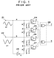
- Figure 1 of the accompanying drawings is a construction diagram showing an example of the signal processing means
- Figure 2 of the accompanying drawings shows signal waveforms in the various circuit portions of Figure 1.
- the reference numerals 21 and 22 designate input terminals to which a sine wave signal S1 and a cosine wave signal C1 are input. That is, in contrast with a signal a (sine wave) from the input terminal 21, a signal b (cosine wave) having a phase difference of 90° is input from the input terminal 22. Also, a signal c given a phase difference of 180° with respect to the signal a is obtained in an inverting circuit 23.
- a pulse circuit 28 is means for obtaining rectangular wave signals of two phases having a phase difference of 90° therebetween. In this manner, signals of higher resolution can be obtained from the sine wave signal and cosine wave signal obtained from the light receiving means.
- the present invention has been made to solve the above-noted problems and an object thereof is to provide a technique whereby even if a fluctuation occurs to the amplitude of a reference periodic signal input, signal processing for higher resolution can be effected highly accurately without being affected by the fluctuation.
- Figure 1 is a construction diagram of a signal circuit according to the prior art.
- FIG. 1 shows signal waveforms in the circuit of Figure 1.
- Figure 3 is a construction diagram of a signal circuit according to an embodiment of the present invention.
- Figure 4 is a construction diagram of a signal circuit according to another embodiment of the present invention.
- Figure 5 is a construction diagram of an encoder using the principle of light interference.
- Figure 6 is a construction diagram of a driving system having the encoder.
- Figure 7 is a construction diagram of a servowriter system for a hard disk.
- a signal processing apparatus has means for inputting a sine wave signal and a cosine wave signal which become a reference, calculating means for creating a sine wave signal of a frequency natural number times as high as the frequency of said reference signals, calculating means for creating a cosine wave signal of a frequency natural number times as high as the frequency of said reference signals, and regulating means for regulating the amplitudes of said created sine wave signal and cosine wave signal of the frequency natural number times as high as the frequency of said reference signals so as to become constant irrespective of the fluctuation of the amplitude of said reference signals.
- Figure 3 is a construction diagram of the signal processing apparatus of the displacement detecting apparatus of the present invention.
- the reference numerals 1 and 2 designate amplitude regulating means
- the reference numerals 3 and 4 denote ⁇ 2 time amplifiers
- the reference numeral 5 designates an adder
- the reference numeral 6 and 10 denote subtractors
- the reference numerals 7, 8 and 9 designate analog multipliers
- the reference numerals 11 and 12 denote dividers.
- the amplitude regulating means 1 and 2 regulate the amplification factors of the input two-phase sine waves C1 and C2, respectively, by variable resistors to thereby obtain two-phase sine wave signals C2 and S2 of the same amplitude P.
- C2 Pcos ⁇ t (3)
- S2 Psin ⁇ t (4) From these signals, a sum signal S3 and a difference signal C3 are produced by the adder 5 and the subtractor 6, respectively.
- the multiplier 8 effects the multiplication of S3 and C3, and the output C4 thereof is
- the multiplier 7 effects the multiplication of outputs obtained by amplifying C2 and S2 by the ⁇ 2 time amplifiers 3 and 4, respectively, and the output S4 thereof is
- a signal A4 obtained by subtracting S4 from the square signal of S3 by the subtractor 10 is
- Figure 4 shows a modification of the above-described construction, and in Figure 4, the same reference numerals as those in Figure 3 designate the same members.
- the reference numerals 13, 14 and 15 denote analog multipliers, the reference numeral 16 designates an adder, and the reference numeral 17 denotes a subtractor.
- the calculating method for obtaining the signals A4 and C4 differs, but the signals obtained are identical and therefore, the same operational effect as that of the embodiment of Figure 3 is obtained.
- one of the ⁇ 2 time amplifiers 3 and 4 may be omitted and the other may be replaced by a two-time amplifier.
- the output of the circuit of the present construction is not affected by the fluctuation of the amplitude of the input signal, and this leads to the following advantages when this output signal is electrically interpolated as a two-phase sine wave signal:
- this signal processing circuit may preferably used in an apparatus such as a displacement detecting apparatus or a laser length measuring machine.
- a displacement detecting apparatus such as a linear encoder or a rotary encoder having the above-described signal processing circuit is shown in Figure 5.
- a light beam emitted from a coherent light source 101 such as a semiconductor laser is split into two light beams by a beam splitter 102, and the two light beams are incident on a single-point position on a diffraction grating 103 which is a movement amount measuring slit formed on a movable scale plate or a rotatable disk plate.
- High-order diffracted lights created from the diffraction grating 103 toward a reflecting optical system 104 by the incidence of the light beams, here ⁇ 1st-order diffracted lights, are both reflected by the reflecting optical system 104 and are again incident on substantially the same position on the diffraction grating 103.
- the reflecting optical system 104 forms a so-called cat's eye optical system.
- ⁇ 1st-order re-diffracted lights created there by the re-incidence return along substantially the same optical path as that during the incidence.
- Interference lights formed by these ⁇ 1st-order re-diffracted lights are made into periodic signals of two phases having a phase difference of 90° therebetween by a polarizing beam splitter 104' and a deflecting plate and are detected by photodetectors 106 and 107, respectively.
- harmonic signals are produced to enhance detection resolution by a processing circuit 108 having the signal processing circuit shown in Figure 3 or 4, and the zero cross point of the waveforms of the created signals is detected to thereby obtain divided pulses, which are output as detection pulses conforming to the displacement of the diffraction grating.
- a number of detection pulses conforming to the amount of displacement (the amount of movement or the amount of rotation) of the diffraction grating relative to the incident light beam are output from the output terminal of the processing circuit 108.
- the direction of rotation or the direction of movement is also detected by the utilization of the phase difference between the two signals.
- Figure 6 shows an example of the use of the above-described encoder, and is a system construction diagram of a driving system using the encoder.
- An encoder unit 111 is connected to the driving output portion of driving means 110 having a drive source such as a motor, an actuator or an engine, or to a moving portion for an object driven, and detects the driven state such as the amount and speed of rotation or the amount and speed of movement.
- This encoder unit has the signal processing circuit described in connection with Figure 3 or 4.
- the detection output from the encoder unit 111 is fed back to control means 112, and a driving signal is transmitted to the driving means 110 so that a condition set by setting means 113 may be brought about in the control means 112.
- Such a driving system can be widely applied to a business machine such as a typewriter, a printer, a copying machine or a facsimile apparatus, a video instrument such as a camera or a video recorder, a recording apparatus, a robot, a machine tool, a manufacturing apparatus and further, any apparatus having driving means.
- Figure 7 shows a specific example using such driving system, and particularly shows the general construction of the servo-writer system of a hard disk.
- the reference numeral 200 designates the surface of a magnetic disk rotated by driving means, not shown
- the reference numeral 201 denotes a motor such as a stepping motor capable of highly accurate rotation
- the reference numeral 203 designates the motor shaft of the motor 201
- the reference numeral 204 denotes an arm portion directly mounted on the motor shaft 203
- the reference numeral 205 designates a track signal writing head attached to the tip end of the arm portion 204.
- the writing head 205 is moved diametrically on the surface 200 of the magnetic disk by the rotation of the motor 201.
- the reference numeral 202 denotes the rotary encoder described above.
- the rotary encoder 202 is mounted on the rotary shaft of the motor 201 and detects the amount of rotation of the motor 201.
- the reference numeral 206 designates a divider having the signal processing circuit described in connection with Figure 3 or 4.
- the divider 206 electrically divides the detection output of the encoder 202 and enhances the detection resolving power.
- the reference numeral 207 denotes a counter for counting the detection pulses from the divider 206.
- the reference numeral 208 designates a controller for synthetically controlling the system.
- the controller 208 has a CPU, a DSP, etc.
- the reference numeral 209 denotes a motor driver for driving the motor 201 on the basis of the command of the controller 208.
- the motor driver 209 has a D/A converter, etc.
- the reference numeral 210 designates a host computer for setting the operation of the system.
- the controller 208 on the basis of the detection by the encoder obtained from the counter 207, gives a command to the motor driver 209 so that the operation of the system may become the operation as set by the host computer 210, and the motor driver 209 drives the motor 201 to thereby move the writing head 205 attached to the tip end of the arm portion 204 diametrically on the surface 200 of the magnetic disk and accurately shift it to a predetermined track position.
- the writing head 205 writes a track signal onto the surface 200 of the magnetic disk.
- the signal processing for higher resolution can be effected without being affected by it.
- original two-phase signals each having the possibility of amplitude fluctuation are received by an input portion.
- new two-phase signals are formed by a signal processing portion.
- the signal processing portion forms an intermediate stage two-phase signal and a phase component eliminated signal having the phase components of the original signals eliminated therefrom in parallel from the original two-phase signals, and eliminates the fluctuation component of amplitude by the offsetting process of respective ones of the two-phase signals and the phase component eliminated signal to thereby form the new two-phase signals.
- the new two-phase signals have a predetermined phase relation with the original two-phase signals.
- the new two-phase signals are output from an output portion.
- This specification also discloses a displacement detecting apparatus using such signal processing apparatus.
Landscapes
- Physics & Mathematics (AREA)
- General Physics & Mathematics (AREA)
- Transmission And Conversion Of Sensor Element Output (AREA)
- Optical Transform (AREA)
Abstract
Description
- This invention relates to signal processing for enhancing detection resolution on the basis of a periodic signal obtained in a displacement detecting apparatus such as an encoder or an interferometer.
- In an optical incremental type rotary encoder or linear encoder, the displacement or the direction of movement of a moving object is detected by the use of two sine wave signals differing in phase (two-phase sine wave signals, in other words, a sine wave signal and a cosine wave signal) obtained from light receiving means. There is known a technique of producing signals differing in phase from said sine wave signal and said cosine wave signal by a signal interpolating process and increasing the number of divided pulses to thereby enhance detection resolution.
- Figure 1 of the accompanying drawings is a construction diagram showing an example of the signal processing means, and Figure 2 of the accompanying drawings shows signal waveforms in the various circuit portions of Figure 1. In Figure 1, the
reference numerals input terminal 21, a signal b (cosine wave) having a phase difference of 90° is input from theinput terminal 22. Also, a signal c given a phase difference of 180° with respect to the signal a is obtained in an invertingcircuit 23. These three signals a, b and c are suitably weight-added by resistors R, and a sine wave signal of any phase (angle) is interpolated. In Figure 1, all the resistors R are of the same value and signals d and e of phase differences 45° and 135°, respectively, are obtained. - These signals are converted into rectangular waves by four
comparators pulse circuit 28 is means for obtaining rectangular wave signals of two phases having a phase difference of 90° therebetween. In this manner, signals of higher resolution can be obtained from the sine wave signal and cosine wave signal obtained from the light receiving means. - Also, discretely from this, an attempt has been made to provide an electrical interpolation method using a combination of an analog multiplier and said resistance division as shown in Japanese Laid-Open Patent Application No. 3-99219, or to output interpolation data in a memory with a value which is obtained by A/D-converting two-phase sine wave signals as an address, thereby obtaining high resolution.
- However, the above-described technique of interpolating an original signal from the phase information of the two-phase sine wave signals of the displacement detecting apparatus such as the encoder or the laser interferometer and enhancing the resolution has suffered from the following problems.
- Generally in the encoder or the interferometer, there is a case where the quantity of reflected light, the quantity of transmitted light or the interference state varies with the movement of an object to be measured, whereby the magnitude of the amplitude of a periodic signal obtained is varied. In such case, the following inconveniences occur:
- (1) When phase division is to be effected by the construction as shown in Figure 1, if the amplitudes of the input signals S1 and C1 vary, the phase with which the rectangular wave is output will be varied by a hysteresis voltage as indicated by dotted lines in Figure 2;
- (2) When two-phase sine wave signals are to be directly A/D-converted, if the signals become small, the quantization error of the A/D converter will become unnegligible and division accuracy will be reduced; and
- (3) When as shown in the aforementioned Japanese Laid-Open Patent Application No. 3-99219, an attempt is made to enhance the resolution by the use of the analog multiplier, the amplitude of the output of the multiplier is proportional to the square of the amplitude of the two-phase sine wave of the original signal and therefore, if for example, the amplitude of the original signal becomes 1/2, the output of the multiplier will become 1/4 and S/N will be extremely reduced.
- The present invention has been made to solve the above-noted problems and an object thereof is to provide a technique whereby even if a fluctuation occurs to the amplitude of a reference periodic signal input, signal processing for higher resolution can be effected highly accurately without being affected by the fluctuation.
- Other objects of the present invention will become apparent from the following description of some embodiments of the present invention.
- Figure 1 is a construction diagram of a signal circuit according to the prior art.
- Figure 2 shows signal waveforms in the circuit of Figure 1.
- Figure 3 is a construction diagram of a signal circuit according to an embodiment of the present invention.
- Figure 4 is a construction diagram of a signal circuit according to another embodiment of the present invention.
- Figure 5 is a construction diagram of an encoder using the principle of light interference.
- Figure 6 is a construction diagram of a driving system having the encoder.
- Figure 7 is a construction diagram of a servowriter system for a hard disk.
- A signal processing apparatus according to an embodiment which will hereinafter be described has means for inputting a sine wave signal and a cosine wave signal which become a reference, calculating means for creating a sine wave signal of a frequency natural number times as high as the frequency of said reference signals, calculating means for creating a cosine wave signal of a frequency natural number times as high as the frequency of said reference signals, and regulating means for regulating the amplitudes of said created sine wave signal and cosine wave signal of the frequency natural number times as high as the frequency of said reference signals so as to become constant irrespective of the fluctuation of the amplitude of said reference signals.
- The invention will hereinafter be described in detail with respect to some embodiments thereof shown in the drawings. Figure 3 is a construction diagram of the signal processing apparatus of the displacement detecting apparatus of the present invention. The
reference numerals 1 and 2 designate amplitude regulating means, thereference numerals reference numeral 5 designates an adder, thereference numeral reference numerals reference numerals - The amplitudes of periodic signals of two phases (sine wave and cosine wave) obtained in a displacement detecting mechanism or the like are not always coincident with each other in a state in which there is no fluctuation in the amplitudes, and two signals C1 and S1 input from input terminals are expressed by the following equations:


where P₁ and P₂ are the amplitudes of the two-phase sine waves. - The amplitude regulating means 1 and 2 regulate the amplification factors of the input two-phase sine waves C1 and C2, respectively, by variable resistors to thereby obtain two-phase sine wave signals C2 and S2 of the same amplitude P.


From these signals, a sum signal S3 and a difference signal C3 are produced by theadder 5 and thesubtractor 6, respectively.
Themultiplier 8 effects the multiplication of S3 and C3, and the output C4 thereof is
Themultiplier 7 effects the multiplication of outputs obtained by amplifying C2 and S2 by the √2time amplifiers 
On the other hand, a signal A4 obtained by subtracting S4 from the square signal of S3 by thesubtractor 10 is
Outputs S5 and C5 obtained by dividing S4 and C4 by A4 by the use of thedividers


As will be seen from equations (10) and (11), even if the amplitude of the original signal varies and the amplitude P of the two-phase sine wave signals C2 and S2 varies, it will not affect the finally obtained periodic signals C5 and S5 of double frequency. - The above-described circuit construction is not restrictive, but other forms are also conceivable. Figure 4 shows a modification of the above-described construction, and in Figure 4, the same reference numerals as those in Figure 3 designate the same members. The
reference numerals reference numeral 16 designates an adder, and thereference numeral 17 denotes a subtractor. In the construction of Figure 4, as compared with the construction of Figure 3, the calculating method for obtaining the signals A4 and C4 differs, but the signals obtained are identical and therefore, the same operational effect as that of the embodiment of Figure 3 is obtained. - Also, if the phase delay by the amplifier poses no problem, one of the √2
time amplifiers - The above-described/processing procedure may be summed up as follows.
- (1) The square signal A4 of the amplitude of the input sine wave signal S2 and cosine wave signal C2 is obtained by the use of the analog multiplier, the adder or the like. This square signal includes the fluctuation information of the amplitude of the reference signal. The phase component is eliminated.
- (2) The signals S4 and C4 of a frequency (resolution) double the frequency of the reference signal are obtained by the use of the analog multipliers
- (3) The sine wave signal S4 and cosine wave signal C4 of double frequency are each divided by said square signal A4 by the use of the dividers to thereby offset the fluctuations of the amplitudes and create the sine wave signal S5 and cosine wave signal C5 of which the frequency is constantly double.
- As described above, the output of the circuit of the present construction is not affected by the fluctuation of the amplitude of the input signal, and this leads to the following advantages when this output signal is electrically interpolated as a two-phase sine wave signal:
- (1) When the two-phase sine wave signal is read in by the A/D converter, any reduction in interpolation accuracy by the quantization error of the A/D converter can be prevented;
- (2) In the case of a system in which the two-phase sine wave signal is read in by the A/D converter and with the data thereof as addresses, the phase information in a memory is called out, the amplitude is constant and therefore, the addresses may be few, that is, the capacity of the memory may be small;
- (3) When phase division is effected, any extreme reduction in S/N ratio does not occur in spite of the multiplier being used;
- (4) Even if use is made of the analog multiplier as shown in Japanese Laid-Open Patent Application No. 3-992l9, little or no reduction in S/N ratio occurs; and
- (5) The two-phase signals S4 and C4 at the intermediate stage and the signal A4 from which the phase component has been eliminated are formed in parallel and by the division of these, the final two-phase signal is formed and therefore, the follow-up delay or the like as when feedback or the like is effected does not occur.
- Now, the signal processing circuit has been described above, and this signal processing circuit may preferably used in an apparatus such as a displacement detecting apparatus or a laser length measuring machine. As an example, the construction of a displacement detecting apparatus such as a linear encoder or a rotary encoder having the above-described signal processing circuit is shown in Figure 5.
- A light beam emitted from a coherent
light source 101 such as a semiconductor laser is split into two light beams by abeam splitter 102, and the two light beams are incident on a single-point position on adiffraction grating 103 which is a movement amount measuring slit formed on a movable scale plate or a rotatable disk plate. High-order diffracted lights created from thediffraction grating 103 toward a reflectingoptical system 104 by the incidence of the light beams, here ±1st-order diffracted lights, are both reflected by the reflectingoptical system 104 and are again incident on substantially the same position on thediffraction grating 103. The reflectingoptical system 104 forms a so-called cat's eye optical system. ±1st-order re-diffracted lights created there by the re-incidence return along substantially the same optical path as that during the incidence. Interference lights formed by these ±1st-order re-diffracted lights are made into periodic signals of two phases having a phase difference of 90° therebetween by a polarizing beam splitter 104' and a deflecting plate and are detected byphotodetectors photodetectors processing circuit 108 having the signal processing circuit shown in Figure 3 or 4, and the zero cross point of the waveforms of the created signals is detected to thereby obtain divided pulses, which are output as detection pulses conforming to the displacement of the diffraction grating. Thus, a number of detection pulses conforming to the amount of displacement (the amount of movement or the amount of rotation) of the diffraction grating relative to the incident light beam are output from the output terminal of theprocessing circuit 108. Further, the direction of rotation or the direction of movement is also detected by the utilization of the phase difference between the two signals. - Figure 6 shows an example of the use of the above-described encoder, and is a system construction diagram of a driving system using the encoder. An
encoder unit 111 is connected to the driving output portion of driving means 110 having a drive source such as a motor, an actuator or an engine, or to a moving portion for an object driven, and detects the driven state such as the amount and speed of rotation or the amount and speed of movement. This encoder unit has the signal processing circuit described in connection with Figure 3 or 4. The detection output from theencoder unit 111 is fed back to control means 112, and a driving signal is transmitted to the driving means 110 so that a condition set by settingmeans 113 may be brought about in the control means 112. By such a feedback system being constituted, the driving condition set by the setting means 113 can be kept. Such a driving system can be widely applied to a business machine such as a typewriter, a printer, a copying machine or a facsimile apparatus, a video instrument such as a camera or a video recorder, a recording apparatus, a robot, a machine tool, a manufacturing apparatus and further, any apparatus having driving means. - Figure 7 shows a specific example using such driving system, and particularly shows the general construction of the servo-writer system of a hard disk. In Figure 7, the
reference numeral 200 designates the surface of a magnetic disk rotated by driving means, not shown, thereference numeral 201 denotes a motor such as a stepping motor capable of highly accurate rotation, thereference numeral 203 designates the motor shaft of themotor 201, thereference numeral 204 denotes an arm portion directly mounted on themotor shaft 203, and thereference numeral 205 designates a track signal writing head attached to the tip end of thearm portion 204. With such construction, the writinghead 205 is moved diametrically on thesurface 200 of the magnetic disk by the rotation of themotor 201. Thereference numeral 202 denotes the rotary encoder described above. Therotary encoder 202 is mounted on the rotary shaft of themotor 201 and detects the amount of rotation of themotor 201. - On the other hand, the
reference numeral 206 designates a divider having the signal processing circuit described in connection with Figure 3 or 4. Thedivider 206 electrically divides the detection output of theencoder 202 and enhances the detection resolving power. Thereference numeral 207 denotes a counter for counting the detection pulses from thedivider 206. Thereference numeral 208 designates a controller for synthetically controlling the system. Thecontroller 208 has a CPU, a DSP, etc. Thereference numeral 209 denotes a motor driver for driving themotor 201 on the basis of the command of thecontroller 208. Themotor driver 209 has a D/A converter, etc. Thereference numeral 210 designates a host computer for setting the operation of the system. - The
controller 208, on the basis of the detection by the encoder obtained from thecounter 207, gives a command to themotor driver 209 so that the operation of the system may become the operation as set by thehost computer 210, and themotor driver 209 drives themotor 201 to thereby move thewriting head 205 attached to the tip end of thearm portion 204 diametrically on thesurface 200 of the magnetic disk and accurately shift it to a predetermined track position. On the basis of a signal from a circuit, not shown, the writinghead 205 writes a track signal onto thesurface 200 of the magnetic disk. - According to the present invention, even if any fluctuation of the amplitude of the input reference signal occurs, the signal processing for higher resolution can be effected without being affected by it.
- In a signal processing apparatus and method, original two-phase signals each having the possibility of amplitude fluctuation are received by an input portion. From the original two-phase signals received by the input portion, new two-phase signals are formed by a signal processing portion. The signal processing portion forms an intermediate stage two-phase signal and a phase component eliminated signal having the phase components of the original signals eliminated therefrom in parallel from the original two-phase signals, and eliminates the fluctuation component of amplitude by the offsetting process of respective ones of the two-phase signals and the phase component eliminated signal to thereby form the new two-phase signals. The new two-phase signals have a predetermined phase relation with the original two-phase signals. The new two-phase signals are output from an output portion. This specification also discloses a displacement detecting apparatus using such signal processing apparatus.
Claims (10)
- A signal processing apparatus, comprising:
an input portion for receiving original two-phase signals each having possibility of amplitude fluctuation;
a signal processing portion for forming new two-phase signals from the original two-phase signals received by said input portion, said signal processing portion forming an intermediate stage two-phase signal and a phase component eliminated signal having the phase components of said original signals eliminated therefrom in parallel from said original two-phase signals, and eliminating the fluctuation component of amplitude by the offsetting process of respective ones of said two-phase signals and said phase component eliminated signal to thereby form said new two-phase signals, said new two-phase signals having a predetermined phase relation with said original two-phase signals; and
an output portion for outputting said new two-phase signals. - A signal processing apparatus according to Claim 1, wherein said signal processing portion has a first circuit for regulating the amplitudes of said original two-phase signals and forming two-phase signals of the same amplitude, a second circuit for forming the sum signal of and the difference signal between said two-phase signals of the same amplitude, a third circuit for forming the multiplied signal of said sum signal and said difference signal as a first signal of said intermediate stage two-phase signal, a fourth circuit for forming the multiplied signal of amplified signals √2 times as great as respective ones of said sum signal and said difference signal as a second signal of said intermediate stage two-phase signal, a fifth circuit for forming the difference signal between said second signal and the square signal of said sum signal as said phase component eliminated signal, and a sixth circuit for dividing said first signal and said second signal by said phase component eliminated signal and forming said new two-phase signals.
- A signal processing apparatus according to Claim 1, wherein said signal processing portion has first means for forming from said original two-phase signals a phase signal of a frequency double the frequency of one of said original two-phase signals, second means for forming from said original two-phase signals a phase signal of a frequency double the frequency of the other of said original two-phase signal, third means for forming said phase component eliminated signal from said original two-phase signals, and fourth means for dividing said phase component eliminated signal by said two phase signals to thereby form said new two-phase signals.
- A signal processing method, comprising:
the reception of original two-phase signals each having the possibility of amplitude fluctuation;
the formation of new two-phase signals from said received original two-phase signals, the formation of said new two-phase signals being executed by the parallel formation of an intermediate stage two-phase signal and a phase component eliminated signal having the phase components of said original signals eliminated therefrom from said original two-phase signals, and the eliminating process of the fluctuation component of amplitude by the offsetting process of respective ones of said two-phase signals and said phase component eliminated signal, said new two-phase signals having a predetermined phase relation with said original two-phase signals; and
the output of said new two-phase signals. - A signal processing method according to Claim 4, wherein the formation of said new two-phase signals has:
the first step of regulating the amplitudes of said original two-phase signals and forming two-phase signals of the same amplitude;
the second step of forming the sum signal of and the difference signal between said two-phase signals of the same amplitude;
the third step of forming the multiplied signal of said sum signal and said difference signal as a first signal of said intermediate stage two-phase signal;
the fourth step of forming the multiplied signal of amplified signals √2 times as great as respective ones of said sum signal and said difference signal as a second signal of said intermediate stage two-phase signal;
the fifth step of forming the difference signal between said second signal and the square signal of said sum signal as said phase component eliminated signal; and
the sixth step of dividing said first signal and said second signal by said phase component eliminated signal and forming said new two-phase signals. - A signal processing method according to Claim 5, wherein the formation of said new two-phase signals has:
the step of forming from said original two-phase signals a phase signal of a frequency double the frequency of one of said original two-phase signals;
the step of forming from said original two-phase signals a phase signal of a frequency double the frequency of the other of said original two-phase signals;
the step of forming said phase component eliminated signal from said original two-phase signals; and
the step of dividing said phase component eliminated signal by said two-phase signals to thereby form said new two-phase signals. - A displacement detecting apparatus, comprising:
a sensor portion for outputting the displacement of a movable portion as two-phase signals corresponding to said displacement; and
a signal processing portion for forming new two-phase signals from the two-phase signals from said sensor portion, said signal processing portion forming an intermediate stage two-phase signal from the two-phase signals from said sensor portion and a signal having the phase component of an original signal eliminated therefrom in parallel, and dividing respective ones of said two-phase signals and said phase component eliminated signal to thereby eliminate the fluctuation component of amplitude and form said new two-phase signals, said new two-phase signals having a predetermined phase relation with the two-phase signals from said sensor portion;
the displacement information of said movable portion being detected by said new two-phase signals. - A displacement detecting apparatus according to Claim 7, wherein said sensor portion has a grating interferometer.
- A displacement detecting apparatus according to Claim 8, wherein said grating interferometer is provided on a motor, and the amount of rotation of said motor as the displacement information is detected by said new two-phase signals.
- A displacement detecting apparatus according to Claim 7, further having control means for controlling the displacement of said movable portion.
Applications Claiming Priority (2)
| Application Number | Priority Date | Filing Date | Title |
|---|---|---|---|
| JP00846992A JP3313750B2 (en) | 1992-01-21 | 1992-01-21 | Signal processing device and device using the same |
| JP8469/92 | 1992-01-21 |
Publications (3)
| Publication Number | Publication Date |
|---|---|
| EP0552726A2 true EP0552726A2 (en) | 1993-07-28 |
| EP0552726A3 EP0552726A3 (en) | 1996-07-24 |
| EP0552726B1 EP0552726B1 (en) | 1998-11-04 |
Family
ID=11693991
Family Applications (1)
| Application Number | Title | Priority Date | Filing Date |
|---|---|---|---|
| EP93100789A Expired - Lifetime EP0552726B1 (en) | 1992-01-21 | 1993-01-20 | Signal processing apparatus and method and displacement detecting apparatus using it |
Country Status (4)
| Country | Link |
|---|---|
| US (1) | US5347355A (en) |
| EP (1) | EP0552726B1 (en) |
| JP (1) | JP3313750B2 (en) |
| DE (1) | DE69321854T2 (en) |
Cited By (5)
| Publication number | Priority date | Publication date | Assignee | Title |
|---|---|---|---|---|
| EP0608810A2 (en) * | 1993-01-27 | 1994-08-03 | SHARP Corporation | Device for controlling printing position |
| DE19501513A1 (en) * | 1995-01-19 | 1996-07-25 | Teves Gmbh Alfred | Method for recognizing a direction of movement, in particular a direction of rotation |
| EP0872714A1 (en) * | 1997-04-16 | 1998-10-21 | Dr. Johannes Heidenhain GmbH | Position measuring device as well as method for operating the same |
| WO2004085971A1 (en) * | 2003-03-25 | 2004-10-07 | Hübner Elektromaschinen AG | Position measuring method and position measuring system used in the multiplication of signal periods |
| DE19861259C5 (en) * | 1997-04-16 | 2010-09-02 | Dr. Johannes Heidenhain Gmbh | Position measuring device and method for operating a position measuring device |
Families Citing this family (16)
| Publication number | Priority date | Publication date | Assignee | Title |
|---|---|---|---|---|
| US5572019A (en) * | 1991-03-12 | 1996-11-05 | Canon Kabushiki Kaisha | Encoder with varying width light receiver and apparatus having the encoder |
| JP3232795B2 (en) * | 1992-08-06 | 2001-11-26 | キヤノン株式会社 | Detector |
| JP3208933B2 (en) * | 1993-06-01 | 2001-09-17 | 株式会社ニコン | Position measuring device |
| US5497226A (en) * | 1994-08-22 | 1996-03-05 | Polaroid Corporation | Quadrature diffractive encoder |
| JPH08145719A (en) * | 1994-09-22 | 1996-06-07 | Canon Inc | Method for detecting position or angle |
| US5646496A (en) * | 1994-11-08 | 1997-07-08 | Dana Corporation | Apparatus and method for generating digital position signals for a rotatable shaft |
| US6351312B1 (en) * | 1997-07-23 | 2002-02-26 | Mitsubishi Denki Kabushiki Kaisha | Interference-type distance measuring device |
| US5936236A (en) * | 1997-11-26 | 1999-08-10 | Renco Encoders, Inc. | Method for generating a synthetic reference signal for comparison with scanning signals of a position measuring device |
| WO2001052406A1 (en) * | 2000-01-13 | 2001-07-19 | Infineon Technologies Ag | Low-noise amplifier circuit and a method for amplifying low-power signals in a low-noise manner |
| ATE346279T1 (en) * | 2001-06-27 | 2006-12-15 | Fraunhofer Ges Forschung | METHOD AND DEVICE FOR PREPARING A SENSOR SIGNAL OF A POSITION SENSOR FOR TRANSMISSION TO AN EVALUATION UNIT |
| WO2004094940A1 (en) * | 2003-04-23 | 2004-11-04 | Nikon Corporation | Interferometer system, signal processing method in interferometer system, stage using the signal processing method |
| JP4428948B2 (en) * | 2003-06-30 | 2010-03-10 | キヤノン株式会社 | Optical encoder |
| US7265339B1 (en) * | 2006-05-22 | 2007-09-04 | Avago Technologies General Ip (Singapore) Pte. Ltd. | Encoder interpolation apparatus |
| US7880658B2 (en) * | 2009-02-26 | 2011-02-01 | Avago Technologies Ecbu Ip (Singapore) Pte. Ltd. | Interpolation accuracy improvement in motion encoder systems, devices and methods |
| JP6207223B2 (en) * | 2013-05-01 | 2017-10-04 | キヤノン株式会社 | Motor drive device and control method thereof |
| JP5877212B2 (en) | 2014-01-10 | 2016-03-02 | キヤノンプレシジョン株式会社 | Encoder, device using encoder, and encoder calculation program |
Citations (2)
| Publication number | Priority date | Publication date | Assignee | Title |
|---|---|---|---|---|
| EP0377045A1 (en) * | 1988-04-18 | 1990-07-11 | Fanuc Ltd. | Encoder |
| JPH0399219A (en) * | 1989-09-13 | 1991-04-24 | Tamagawa Seiki Co Ltd | Encoder |
-
1992
- 1992-01-21 JP JP00846992A patent/JP3313750B2/en not_active Expired - Fee Related
-
1993
- 1993-01-19 US US08/005,576 patent/US5347355A/en not_active Expired - Lifetime
- 1993-01-20 EP EP93100789A patent/EP0552726B1/en not_active Expired - Lifetime
- 1993-01-20 DE DE69321854T patent/DE69321854T2/en not_active Expired - Lifetime
Patent Citations (2)
| Publication number | Priority date | Publication date | Assignee | Title |
|---|---|---|---|---|
| EP0377045A1 (en) * | 1988-04-18 | 1990-07-11 | Fanuc Ltd. | Encoder |
| JPH0399219A (en) * | 1989-09-13 | 1991-04-24 | Tamagawa Seiki Co Ltd | Encoder |
Non-Patent Citations (1)
| Title |
|---|
| PATENT ABSTRACTS OF JAPAN vol. 015, no. 287 (P-1229), 22 July 1991 & JP-A-03 099219 (TAMAGAWA), 24 April 1991, * |
Cited By (11)
| Publication number | Priority date | Publication date | Assignee | Title |
|---|---|---|---|---|
| EP0608810A2 (en) * | 1993-01-27 | 1994-08-03 | SHARP Corporation | Device for controlling printing position |
| EP0608810A3 (en) * | 1993-01-27 | 1995-08-23 | Sharp Kk | Device for controlling printing position. |
| DE19501513A1 (en) * | 1995-01-19 | 1996-07-25 | Teves Gmbh Alfred | Method for recognizing a direction of movement, in particular a direction of rotation |
| EP0872714A1 (en) * | 1997-04-16 | 1998-10-21 | Dr. Johannes Heidenhain GmbH | Position measuring device as well as method for operating the same |
| US6265992B1 (en) | 1997-04-16 | 2001-07-24 | Dr. Johannes Heidenhain Gmbh | Position measuring system and method for operating a position measuring system |
| EP1610096A2 (en) * | 1997-04-16 | 2005-12-28 | Dr. Johannes Heidenhain GmbH | Position measuring device and method for operating a position measuring device |
| EP1610096A3 (en) * | 1997-04-16 | 2006-04-26 | Dr. Johannes Heidenhain GmbH | Position measuring device and method for operating a position measuring device |
| DE19815438B4 (en) * | 1997-04-16 | 2007-08-02 | Dr. Johannes Heidenhain Gmbh | Position measuring device and method for operating a position measuring device |
| DE19861259C5 (en) * | 1997-04-16 | 2010-09-02 | Dr. Johannes Heidenhain Gmbh | Position measuring device and method for operating a position measuring device |
| WO2004085971A1 (en) * | 2003-03-25 | 2004-10-07 | Hübner Elektromaschinen AG | Position measuring method and position measuring system used in the multiplication of signal periods |
| US7251575B2 (en) | 2003-03-25 | 2007-07-31 | Hubner Electromaschinen Gmbh | Position measuring method and position measuring system used in the multiplication of signal periods |
Also Published As
| Publication number | Publication date |
|---|---|
| JPH05196479A (en) | 1993-08-06 |
| DE69321854T2 (en) | 1999-05-12 |
| EP0552726A3 (en) | 1996-07-24 |
| DE69321854D1 (en) | 1998-12-10 |
| EP0552726B1 (en) | 1998-11-04 |
| US5347355A (en) | 1994-09-13 |
| JP3313750B2 (en) | 2002-08-12 |
Similar Documents
| Publication | Publication Date | Title |
|---|---|---|
| US5347355A (en) | Signal processing apparatus and method, and displacement detecting apparatus using the same | |
| EP0463561B1 (en) | Signal processing method and apparatus, and a system such as a displacement detecting device using the same | |
| US5909333A (en) | Servo-writing system for use in a data recording disk drive | |
| EP0586454B1 (en) | Positional measurement | |
| US4850695A (en) | Test system for optical disks | |
| EP0397202A2 (en) | Encoder | |
| US6265992B1 (en) | Position measuring system and method for operating a position measuring system | |
| CA2200286C (en) | Tracking control apparatus and method | |
| US4870635A (en) | Precision measurement and positioning system for disk storage system | |
| US5274511A (en) | Servo signal recording method and apparatus | |
| US5182613A (en) | Position detecting apparatus generating periodic detection signals having equal third and fifth harmonic components | |
| US6667696B2 (en) | Sensor system for measuring angles and positions | |
| CN116222372A (en) | Quick reflector angle calibration method and system | |
| US4705996A (en) | Apparatus for positioning a rotating element | |
| EP1367586B1 (en) | Positioning control device and positioning control method | |
| JPH09250907A (en) | Positioning method for piezoelectric element and positioning accuracy-confirming method | |
| JPH0658769A (en) | Signal processing method and displacement detector using method thereof | |
| During | Real-time optical measurement of position | |
| JPS628489Y2 (en) | ||
| KR930008492B1 (en) | Positioning servosystem for cdp | |
| JP2691939B2 (en) | Electromagnetically coupled position detector | |
| EP0394942A2 (en) | A signal insertion processor and an encoder using the processor | |
| JPH057641B2 (en) | ||
| NL1010156C2 (en) | Positioning system and device equipped with the positioning system. | |
| JPS5851225B2 (en) | electromagnetic oscillographic device |
Legal Events
| Date | Code | Title | Description |
|---|---|---|---|
| PUAI | Public reference made under article 153(3) epc to a published international application that has entered the european phase |
Free format text: ORIGINAL CODE: 0009012 |
|
| AK | Designated contracting states |
Kind code of ref document: A2 Designated state(s): DE FR GB IT |
|
| PUAL | Search report despatched |
Free format text: ORIGINAL CODE: 0009013 |
|
| AK | Designated contracting states |
Kind code of ref document: A3 Designated state(s): DE FR GB IT |
|
| 17P | Request for examination filed |
Effective date: 19961210 |
|
| 17Q | First examination report despatched |
Effective date: 19970226 |
|
| GRAG | Despatch of communication of intention to grant |
Free format text: ORIGINAL CODE: EPIDOS AGRA |
|
| GRAG | Despatch of communication of intention to grant |
Free format text: ORIGINAL CODE: EPIDOS AGRA |
|
| GRAG | Despatch of communication of intention to grant |
Free format text: ORIGINAL CODE: EPIDOS AGRA |
|
| GRAH | Despatch of communication of intention to grant a patent |
Free format text: ORIGINAL CODE: EPIDOS IGRA |
|
| GRAH | Despatch of communication of intention to grant a patent |
Free format text: ORIGINAL CODE: EPIDOS IGRA |
|
| GRAA | (expected) grant |
Free format text: ORIGINAL CODE: 0009210 |
|
| AK | Designated contracting states |
Kind code of ref document: B1 Designated state(s): DE FR GB IT |
|
| REF | Corresponds to: |
Ref document number: 69321854 Country of ref document: DE Date of ref document: 19981210 |
|
| ET | Fr: translation filed | ||
| ITF | It: translation for a ep patent filed |
Owner name: SOCIETA' ITALIANA BREVETTI S.P.A. |
|
| PLBE | No opposition filed within time limit |
Free format text: ORIGINAL CODE: 0009261 |
|
| STAA | Information on the status of an ep patent application or granted ep patent |
Free format text: STATUS: NO OPPOSITION FILED WITHIN TIME LIMIT |
|
| 26N | No opposition filed | ||
| REG | Reference to a national code |
Ref country code: GB Ref legal event code: IF02 |
|
| PGFP | Annual fee paid to national office [announced via postgrant information from national office to epo] |
Ref country code: IT Payment date: 20090121 Year of fee payment: 17 |
|
| PGFP | Annual fee paid to national office [announced via postgrant information from national office to epo] |
Ref country code: FR Payment date: 20090121 Year of fee payment: 17 |
|
| REG | Reference to a national code |
Ref country code: FR Ref legal event code: ST Effective date: 20100930 |
|
| PG25 | Lapsed in a contracting state [announced via postgrant information from national office to epo] |
Ref country code: FR Free format text: LAPSE BECAUSE OF NON-PAYMENT OF DUE FEES Effective date: 20100201 |
|
| PG25 | Lapsed in a contracting state [announced via postgrant information from national office to epo] |
Ref country code: IT Free format text: LAPSE BECAUSE OF NON-PAYMENT OF DUE FEES Effective date: 20100120 |
|
| PGFP | Annual fee paid to national office [announced via postgrant information from national office to epo] |
Ref country code: DE Payment date: 20110131 Year of fee payment: 19 |
|
| PGFP | Annual fee paid to national office [announced via postgrant information from national office to epo] |
Ref country code: GB Payment date: 20110125 Year of fee payment: 19 |
|
| GBPC | Gb: european patent ceased through non-payment of renewal fee |
Effective date: 20120120 |
|
| PG25 | Lapsed in a contracting state [announced via postgrant information from national office to epo] |
Ref country code: GB Free format text: LAPSE BECAUSE OF NON-PAYMENT OF DUE FEES Effective date: 20120120 Ref country code: DE Free format text: LAPSE BECAUSE OF NON-PAYMENT OF DUE FEES Effective date: 20120801 |
|
| REG | Reference to a national code |
Ref country code: DE Ref legal event code: R119 Ref document number: 69321854 Country of ref document: DE Effective date: 20120801 |