EP0543386A2 - Method of and apparatus for processing image data - Google Patents
Method of and apparatus for processing image data Download PDFInfo
- Publication number
- EP0543386A2 EP0543386A2 EP92119750A EP92119750A EP0543386A2 EP 0543386 A2 EP0543386 A2 EP 0543386A2 EP 92119750 A EP92119750 A EP 92119750A EP 92119750 A EP92119750 A EP 92119750A EP 0543386 A2 EP0543386 A2 EP 0543386A2
- Authority
- EP
- European Patent Office
- Prior art keywords
- image data
- pixel density
- sharpness
- surrounding
- data
- Prior art date
- Legal status (The legal status is an assumption and is not a legal conclusion. Google has not performed a legal analysis and makes no representation as to the accuracy of the status listed.)
- Granted
Links
- 238000000034 method Methods 0.000 title claims description 49
- 238000012545 processing Methods 0.000 title claims description 49
- 238000009499 grossing Methods 0.000 claims description 13
- 230000008569 process Effects 0.000 description 26
- 230000015654 memory Effects 0.000 description 15
- 238000012937 correction Methods 0.000 description 5
- 238000010586 diagram Methods 0.000 description 5
- 238000006243 chemical reaction Methods 0.000 description 4
- 230000002708 enhancing effect Effects 0.000 description 4
- 230000004044 response Effects 0.000 description 4
- 230000000694 effects Effects 0.000 description 3
- 230000003287 optical effect Effects 0.000 description 3
- 238000012546 transfer Methods 0.000 description 2
- 230000001934 delay Effects 0.000 description 1
- 230000003111 delayed effect Effects 0.000 description 1
- 238000012986 modification Methods 0.000 description 1
- 230000004048 modification Effects 0.000 description 1
- 230000009467 reduction Effects 0.000 description 1
- 230000000007 visual effect Effects 0.000 description 1
Images


Classifications
-
- G—PHYSICS
- G06—COMPUTING; CALCULATING OR COUNTING
- G06T—IMAGE DATA PROCESSING OR GENERATION, IN GENERAL
- G06T5/00—Image enhancement or restoration
- G06T5/70—Denoising; Smoothing
-
- G—PHYSICS
- G06—COMPUTING; CALCULATING OR COUNTING
- G06T—IMAGE DATA PROCESSING OR GENERATION, IN GENERAL
- G06T5/00—Image enhancement or restoration
- G06T5/20—Image enhancement or restoration using local operators
-
- G—PHYSICS
- G06—COMPUTING; CALCULATING OR COUNTING
- G06T—IMAGE DATA PROCESSING OR GENERATION, IN GENERAL
- G06T5/00—Image enhancement or restoration
- G06T5/73—Deblurring; Sharpening
Definitions
- the present invention relates to a method of and an apparatus for processing image data, wherein when image data to be outputted is processed for smoothing or enhancement of sharpness, the same result of processing can be obtained at all times without depending on the pixel density, by processing the image data based on the pixel density of the outputted image data.
- a system which causes an optical system to read image information of a copy or subject to thereby produce image data and subjects the produced image data to various image processes so as to be outputted to a printer or the like.
- This type of system is widely used in the printing and platemaking fields in particular.
- a personal computer, a work station, etc. have rapidly been advanced in recent years and has come to deal even with image data. For example, characters and images have conventionally been cut and patched up by hand to produce a copy.
- DTP Desk Top Publishing
- a composing process in the printing field is effected by a composing system using the work station or the like or by a total scanner or the like.
- the input/output device referred to above sometimes processes the image data for smoothing and enhancement of sharpness.
- the conversion of the pixel density is effected upon processing of the image data for smoothing and enhancement of sharpness, this results in different processes.
- It is a still further object of the present invention to provide a method of processing image data S set and outputted at a predetermined pixel density for enhancement of sharpness, using image data surround - ing the image data S, comprising the steps of smoothing the image data S, using the surrounding image data falling within an area set so as to be substantially proportional to the predetermined pixel density to thereby produce smoothed image data U, and thereafter producing sharpness-enhanced image data S * represented as S * S + K•(S - U), using the image data S, the smoothed image data U and a predetermined sharpness enhancement coefficient K.
- It is a still further object of the present invention to provide a method of processing image data S set and outputted at a predetermined pixel density for enhancement of sharpness, wherein the relationship between the sharpness enhancement coefficient K and the mask size M is set onto a curve which passes through points close to points (K, M) (6, 3), (2.5, 5), (1.5, 7), (1, 11).
- It is a still further object of the present invention to provide a sharpness enhancement processing apparatus for processing image data S set and outputted at a predetermined pixel density for enhancement of sharpness, using image data surrounding the image data S, comprising range setting means for setting the area of the surrounding image data based on the predetermined pixel density, smoothed image data generating means for processing the image data S for smoothness using the surrounding image data falling within the area set by the range setting means to thereby produce smoothed image data U, and image data generating means for generating sharpness - enhanced image data S * defined as S * S + K•(S - U), using the image data S, the smoothed image data U and a predetermined sharpness enhancement coefficient K.
- the smoothed image data generating means comprises a plurality of storing means for storing therein image data as line data arranged in a main scanning direction, selecting means for selecting image data arranged in the main scanning direction and an auxiliary scanning direction corresponding to the range of the surrounding image data from the storing means, adding means for adding the selected image data together, and dividing means for dividing the added image data by the number of the selected image data.
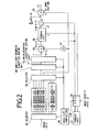
- FIG. 1 is a block diagram schematically showing the structure of an image data processing apparatus 10 according to one embodiment of the present invention.
- an image recorded on a copy or subject 12 which is fed in an auxiliary scanning direction, is scanned or read in a main scanning direction by a CCD 16 via a condenser lens 14.
- the read image data is subjected to predetermined processing and transferred to a work station or the like.
- the work station or the like processes the image data for predetermined editing and transmits the same to an output device such as a printer or the like.
- the image data processing apparatus 10 comprises an A/D converter 18 for converting image data converted into an electrical signal by the CCD 16 into a digital signal, a correction circuit 20 for processing the image data converted into the digital signal for compensation for the dark current caused by the CCD 16, compensation for shading caused by a read optical system, etc., a gradation converter 22 for converting the gradation of the image data, a pixel density converter 24 for converting a pixel density of the image data into a pixel density processable by the work station or the like, a sharpness enhancement processing circuit 26 for processing the image data for enhancement of sharpness, and a pixel density setting unit 28 for setting a desired pixel density and for supplying data about the set pixel density to the pixel density converter 24 and the sharpness enhancement processing circuit 26.
- the pixel density converter 24 effects pixel density converting processes such as an image data thinning process, an interpolating process, etc.
- image data S ij * processed for sharpness enhancement is generated by using the image data S ij , the smoothed image data U ij and a given sharpness enhancement coefficient K as follows:
- the mask size data may be processed so as to be arranged M in the main scanning direction and N in the auxiliary scanning direction (M # N) upon generation of the image data S ij *•.
- ⁇ M ⁇ j + P (P (N - 1)/2) and M 2 may be set as M - N.
- FIG. 2 is a block diagram showing the structure of the sharpness enhancement processing circuit 26.
- the sharpness enhancement processing circuit 26 comprises a CPU 30 for determining a sharpness enhancement coefficient K and mask size data M based on pixel density data p supplied from the pixel density setting unit 28, a storage unit 32 for storing therein the sharpness enhancement coefficient K and the mask size data M determined based on the pixel density data p, and a mask size controller 34 for outputting a control signal in response to the mask size data M.
- the sharpness enhancement processing circuit 26 also includes a plurality of line memories LM1, LM2, ...
- FIG. 3 shows the configuration of the auxiliary - scanning direction adding unit 40.
- the auxiliary - scanning direction adding unit 40 comprises a line memory LM for storing image data supplied from the line memories LM1 through LMn as image data fed in the auxiliary scanning direction, a subtractor 50 for subtracting image data outputted from the line memory LM and whose given number of pixels is shifted, from the image data outputted from the line memories LM1 through LMn, a register 52 for temporarily storing therein image data to be outputted to the main scanning direction adding unit 42, and an adder 54 for adding the output of the subtractor 50 to the output of the register 52 so as to re-output the result of addition to the register 52.
- the main-scanning direction adding unit 42 is constructed such that a shift register is used as an alternative to the line memory LM of the auxiliary - scanning direction adding unit 40.
- Other elements of structure are identical to those employed in the auxiliary - scanning direction adding unit 40, and their description will therefore be omitted.
- the image data processing apparatus 10 is basically constructed as described above. The operation of the image data processing apparatus 10 will now be described below.
- Image information which has been recorded on the copy 12 is first read by the CCD 16 using the condenser lens 14. The read image information is then converted into an analog signal. The converted analog signal is converted into image data serving as a digital signal by the A/D converter 18, followed by transfer to the correction circuit 20.
- the correction circuit 20 processes the image data for the correction relative to the dark current caused by the CCD 16, the correction of shading caused by the read optical system, etc.
- the gradation of the image data which has been subjected to the above processing is converted into desired gradation in the gradation converter 22. Thereafter, the pixel density converter 24 converts the pixel density of the image data into a pixel density treatable by an external work station or the like for effecting an editing process of the image data.
- the pixel density converter 24 performs pixel density converting processes such as a thinning process (reduction), a linear interpolating process, an Hermite interpolating process (enlargement), etc. on the image data based on the pixel density data p outputted from the pixel density setting unit 28.
- the sharpness enhancement processing circuit 26 processes the image data subjected to the pixel density conversion for enhancement of sharpness. This process will be described in accordance with circuits shown in FIGS. 2 and 3.
- the CPU 30 first reads corresponding mask size data M and a corresponding sharpness enhancement coefficient K from the storage unit 32 in response to the pixel density data p supplied from the pixel density setting unit 28.
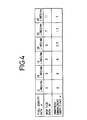
- FIG. 4 shows a data table which has been stored in the storage unit 32.
- 12 lines/mm represent pixel density data p in the case where an image is made up of 12 scanning lines per mm.
- the mask size data M for generating smoothed image data U, with respect to the pixel density data p is set to 3.
- the size of one pixel is:
- an output image range for producing the smoothed image data U is:
- mask size data M with respect to other pixel density data p are set in such a manner that the output image range falls between 200 ⁇ m and 250 /1.m. That is, the mask size data M is set so as to be substantially proportional to the pixel density data p.
- the output image range for generating the smoothed image data U is set so as to be substantially constant in the range of 200 ⁇ m to 250 ⁇ m. Therefore, a process for obtaining image data S * processed for sharpness enhancement in accordance with the equation (2) can be effected within the same output image range. Accordingly, the same result of processing can be obtained irrespective of the pixel density.
- the range of 200 ⁇ m to 250 ⁇ m represents the optimum range judging from visual characteristics of a human being.
- FIG. 5 is a graph for describing the relationship between the mask size data M and the sharpness enhancement coefficient K.
- the sharpness enhancing process depends on the sharpness enhancement coefficient K as well as the mask size data M.
- the relationship between the pixel density data p, the mask size data M and the sharpness enhancement coefficient K is shown in the data table of FIG. 4.
- the mask size data M which has been read from the storage unit 32 by the CPU 30, is supplied to the mask size controller 34 and the sharpness enhancement coefficient K is supplied to the storage unit 46.
- the pixel density, the mask size data M and the sharpness enhancement coefficient K will be described below as being 12 lines/mm, 3 and 6, for example, respectively.
- the auxiliary-scanning direction adding unit 40 reads image data, at the same main scanning positions, of the line memories LM1 through LM3 in the auxiliary scanning direction. Then, the read image data are successively stored in the line memory LM as image data arranged in the auxiliary scanning direction and supplied to the subtractor 50 in succession.
- the line memory LM delays the image data a time interval corresponding to three pixels because the mask size data M is 3, and outputs the delayed image data to the subtractor 50.
- the output of the subtractor 50 is supplied to the register 52 via the adder 54 and added to the adder 54 again.
- FIG. 6 shows image data at respective points (A through E) in the auxiliary - scanning direction adding unit 40 at the time that the column of image data in the main scanning direction, which are supplied from the selector 38, is represented by a through i.
- a, b, c, ... are expressed by the following equations respectively:
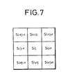
- an image data column T i * is outputted from the auxiliary-scanning direction adding unit 40 in accordance with the relationship shown in FIG. 6 assuming that image data S i-1j-1 through S i+1j+1 are arranged as shown in FIG. 7.
- the image data column T i * is expressed as follows:
- image data T ij added together within a mask i.e., in - mask added image data T ij is determined by effecting serial - parallel conversion using a shift register as an alternative to the line memory LM of the auxiliary-scanning direction adding unit 40 and adding the image data T ij * in the main scanning direction.
- the image data T ij is expressed as follows: Incidentally, the relationship between the smoothed image data U ij determined from the equation (1) and the in - mask added image data T ij is derived as follows:
- the in - mask added image data T ij is then inverted. Thereafter, the adder 44 adds (actually subtracts the image data T ij from data obtained by multiplying the image data S ij supplied from the selector 38 to the multiplier 43 by M 2 in the multiplier 43) the image data T ij to the data thus obtained, and supplies the added data to the storage unit 46.
- data K• M 2 • S - T
- the storage unit 46 data K• (M 2 • S - T) is determined from the data supplied from the adder 44 and the sharpness enhancement coefficient K supplied from the CPU 30, and supplied to the divider 47.
- the divider 47 the data is divided by the data M 2 supplied from the CPU 30, and the so - divided data is applied to the adder 48.
- the adder 48 adds the image data S ij to the divided data so as to produce the image data S ij * represented by the equation (2).
- the accuracy of calculation can be improved by using the image data T ij defined as the equation (10) as an alternative to the smoothed image data U ij defined as the equation (1).
- the image data S ij is outputted to the work station or the like, where it is subjected to a desired editing process.
- the image data S ij * has been processed for enhancement of sharpness according to the pixel density treatable by the work station or the like. Therefore, the degree of the sharpness enhancement with respect to an image is not affected by the pixel density, and the same sharpness enhancement can be achieved at all times.
- the present embodiment can bring about the same effects even when a smoothing process (a process for obtaining the smoothed image data U) is carried out.
- the area of image data which is of an object of either a smoothing process or a sharpness enhancing process is set up according to the pixel density of output image data. Further, a sharpness enhancement coefficient is also set up as required. Therefore, image data which has been subjected to a given process, can be obtained without depending on the pixel density.
Landscapes
- Physics & Mathematics (AREA)
- General Physics & Mathematics (AREA)
- Engineering & Computer Science (AREA)
- Theoretical Computer Science (AREA)
- Image Processing (AREA)
- Facsimile Image Signal Circuits (AREA)
- Editing Of Facsimile Originals (AREA)
Abstract

[where L = (M - 1)/2]
Description
- The present invention relates to a method of and an apparatus for processing image data, wherein when image data to be outputted is processed for smoothing or enhancement of sharpness, the same result of processing can be obtained at all times without depending on the pixel density, by processing the image data based on the pixel density of the outputted image data.
- A system is known which causes an optical system to read image information of a copy or subject to thereby produce image data and subjects the produced image data to various image processes so as to be outputted to a printer or the like. This type of system is widely used in the printing and platemaking fields in particular.
- Now, a personal computer, a work station, etc. have rapidly been advanced in recent years and has come to deal even with image data. For example, characters and images have conventionally been cut and patched up by hand to produce a copy. However, DTP (Desk Top Publishing) has recently been widespread which transfers image information from an image information input/output device to a work station to thereby compose the transferred image information thereat. In particular, a composing process in the printing field is effected by a composing system using the work station or the like or by a total scanner or the like.
- It is sometimes necessary to effect the conversion of the pixel density of image data which is an object to be processed between the image information input/output device and the work station or the like when the work station or the like is used. That is, a pixel density treatable by the image information input/output device and a pixel density treatable by the work station or the like are normally different from each other. It is therefore necessary to adjust these pixel densities.
- On the other hand, the input/output device referred to above sometimes processes the image data for smoothing and enhancement of sharpness. Thus, when the conversion of the pixel density is effected upon processing of the image data for smoothing and enhancement of sharpness, this results in different processes.
- It is therefore an object of the present invention to provide a method of and an apparatus for processing image data, wherein when image data to be outputted is processed for smoothing and enhancement of sharpness, the same result of processing can be obtained at all times without depending on the pixel density of the image data.
- It is another object of the present invention to provide a method of smoothing image data set and outputted at a predetermined pixel density, using image data surrounding the image data, comprising the step of processing the image data for smoothness, using the surrounding image data falling within an area set so as to be substantially proportional to the predetermined pixel density.
- It is a further object of the present invention to provide a method of smoothing image data, wherein the area represented by M is set so as to meet the following equation:

where - p = pixel density
- M = mask size substantially proportional to the predetermined pixel density.
- It is a still further object of the present invention to provide a method of smoothing image data, wherein the constant value C is set so as to fall within a range of 200 /1.m to 250 /1.m.
- It is a still further object of the present invention to provide a method of smoothing image data, wherein image data Sij (i = 1, ... m, j = 1, ... n) is converted into smoothed image data Uij processed as defined by the following equation, using M x N surrounding image data set by mask size data M, N each substantially proportional to the pixel density.

[where L = (M -1)/2, P = (N 1)12] - It is a still further object of the present invention to provide a method of processing image data S set and outputted at a predetermined pixel density for enhancement of sharpness, using image data surround - ing the image data S, comprising the steps of smoothing the image data S, using the surrounding image data falling within an area set so as to be substantially proportional to the predetermined pixel density to thereby produce smoothed image data U, and thereafter producing sharpness-enhanced image data S* represented as S* = S + K•(S - U), using the image data S, the smoothed image data U and a predetermined sharpness enhancement coefficient K.
- It is a still further object of the present invention to provide a method of processing image data S set and outputted at a predetermined pixel density for enhancement of sharpness, wherein the mask size represented by M is set so as to meet the following equation:

where - p = pixel density
- M = mask size substantially proportional to the predetermined pixel density.
- It is a still further object of the present invention to provide a method of processing image data S set and outputted at a predetermined pixel density for enhancement of sharpness, wherein the constant value C is set so as to fall within a range of 200 µm to 250 µm.
- It is a still further object of the present invention to provide a method of processing image data S set and outputted at a predetermined pixel density for enhancement of sharpness, wherein the sharpness enhancement coefficient K is set depending on the range of the surrounding image data.
- It is a still further object of the present invention to provide a method of processing image data S set and outputted at a predetermined pixel density for enhancement of sharpness, wherein the relationship between the sharpness enhancement coefficient K and the mask size M is set onto a curve which passes through points close to points (K, M) = (6, 3), (2.5, 5), (1.5, 7), (1, 11).
- It is a still further object of the present invention to provide a method of processing image data S set and outputted at a predetermined pixel density for enhancement of sharpness, wherein image data Sij (i = 1, ... m, j = 1, ... n) is converted into smoothed image data Uij processed as defined by the following equation, using M x N surrounding image data set by mask size data M, N each substantially proportional to the pixel density.

[where L = (M -1)/2, P = (N 1)12] - It is a still further object of the present invention to provide a sharpness enhancement processing apparatus for processing image data S set and outputted at a predetermined pixel density for enhancement of sharpness, using image data surrounding the image data S, comprising range setting means for setting the area of the surrounding image data based on the predetermined pixel density, smoothed image data generating means for processing the image data S for smoothness using the surrounding image data falling within the area set by the range setting means to thereby produce smoothed image data U, and image data generating means for generating sharpness - enhanced image data S* defined as S* = S + K•(S - U), using the image data S, the smoothed image data U and a predetermined sharpness enhancement coefficient K.
- It is a still further object of the present invention to provide a sharpness enhancement processing apparatus wherein the range of the surrounding image data and the sharpness enhancement coefficient K are set as a look-up table corresponding to the pixel density.
- It is a still further object of the present invention to provide a sharpness enhancement processing apparatus wherein the smoothed image data generating means comprises a plurality of storing means for storing therein image data as line data arranged in a main scanning direction, selecting means for selecting image data arranged in the main scanning direction and an auxiliary scanning direction corresponding to the range of the surrounding image data from the storing means, adding means for adding the selected image data together, and dividing means for dividing the added image data by the number of the selected image data.
- The above and other objects, features and advantages of the present invention will become apparent from the following description and the appended claims, taken in conjunction with the accompanying drawings in which a preferred embodiment of the present invention is shown by way of illustrative example.
-
- FIG. 1 is a schematic block diagram showing the structure of an image data processing apparatus according to one embodiment of the present invention;
- FIG. 2 is a detailed block diagram illustrating the structure of a sharpness enhancement processing circuit of the image data processing apparatus shown in FIG. 1;
- FIG. 3 is a detailed block diagram depicting the structure of an auxiliary - scanning direction adding unit of the sharpness enhancement processing circuit shown in FIG. 2;
- FIG. 4 is a view for describing a data table stored in a storage unit of the sharpness enhancement processing circuit shown in FIG. 2;
- FIG. 5 is a view for describing the relationship between mask size data and sharpness enhancement coefficients shown in FIG. 4;
- FIG. 6 is a view for describing image data at respective points in the auxiliary - scanning direction adding unit shown in FIG. 3; and
- FIG. 7 is a view for describing image data processed for enhancement of sharpness.
- FIG. 1 is a block diagram schematically showing the structure of an image
data processing apparatus 10 according to one embodiment of the present invention. In the imagedata processing apparatus 10, an image recorded on a copy orsubject 12 which is fed in an auxiliary scanning direction, is scanned or read in a main scanning direction by aCCD 16 via acondenser lens 14. The read image data is subjected to predetermined processing and transferred to a work station or the like. Incidentally, the work station or the like processes the image data for predetermined editing and transmits the same to an output device such as a printer or the like. - The image
data processing apparatus 10 comprises an A/D converter 18 for converting image data converted into an electrical signal by theCCD 16 into a digital signal, acorrection circuit 20 for processing the image data converted into the digital signal for compensation for the dark current caused by theCCD 16, compensation for shading caused by a read optical system, etc., agradation converter 22 for converting the gradation of the image data, apixel density converter 24 for converting a pixel density of the image data into a pixel density processable by the work station or the like, a sharpnessenhancement processing circuit 26 for processing the image data for enhancement of sharpness, and a pixeldensity setting unit 28 for setting a desired pixel density and for supplying data about the set pixel density to thepixel density converter 24 and the sharpnessenhancement processing circuit 26. Incidentally, the pixel density converter 24 effects pixel density converting processes such as an image data thinning process, an interpolating process, etc. - In the sharpness
enhancement processing circuit 26, the image data is processed in principle for enhancement of sharpness in the following manner. That is, let's now consider that the image data of thecopy 12 comprises m pixels arranged along the main scanning direction and n pixels arranged along the auxiliary scanning direction. Further, the image data corresponding to the respective pixels is represented as Sij (i = 1 ... m, j = 1 ... n). In the sharpnessenhancement processing circuit 26, the image data Sij is regarded as the center and M x M (M: mask size data, M m, n) image data around the image data Sij are taken out along the main and auxiliary scanning directions. The image data thus taken out are the smoothed, thereby producing smoothed image data Uij represented as follows:
[where L = (M - 1)12] - Next, image data Sij* processed for sharpness enhancement is generated by using the image data Sij, the smoothed image data Uij and a given sharpness enhancement coefficient K as follows:

- Incidentally, the mask size data may be processed so as to be arranged M in the main scanning direction and N in the auxiliary scanning direction (M # N) upon generation of the image data Sij*•. In this case, M may be set to fall between j - P and j + P (P = (N - 1)/2) (i.e., j - P|≦ M≦ j + P (P = (N - 1)/2) and M2 may be set as M - N.
- FIG. 2 is a block diagram showing the structure of the sharpness
enhancement processing circuit 26. The sharpnessenhancement processing circuit 26 comprises aCPU 30 for determining a sharpness enhancement coefficient K and mask size data M based on pixel density data p supplied from the pixeldensity setting unit 28, astorage unit 32 for storing therein the sharpness enhancement coefficient K and the mask size data M determined based on the pixel density data p, and a mask size controller 34 for outputting a control signal in response to the mask size data M. Further, the sharpnessenhancement processing circuit 26 also includes a plurality of line memories LM1, LM2, ... LMn for storing image data therein for each main scanning line of the original 12, and selectors 36, 38 each used to store image data in a predetermined line memory LMn (n = 1, 2, ...) in response to the control signal supplied from the mask size controller 34 and to select desired image data from the predetermined line memory LMn, an auxiliary - scanning direction adding unit 40 and a main-scanning direction adding unit 42 for adding image data in the auxiliary and main scanning directions respectively to thereby generate smoothed image data Uij, a multiplier 43 for multiplying image data Sij outputted from the selector 38 by the square of the mask size data M, an adder 44 for adding the smoothed image data Uij outputted from the main-scanning direction adding unit 42 and whose sign is inverted to data outputted from the multiplier 43, a storage unit 46 for storing a table indicative of preset image data therein, selecting predetermined image data based on the sharpness enhancement coefficient K determined by the CPU 30 and the image data outputted from the adder 44, and outputting the same therefrom, a divider 47 for dividing the image data outputted from the storage unit 46 by the square of the mask size data M determined by the CPU 30, and an adder 48 for adding image data outputted from the divider 47 to the image data Sij outputted from the selector 38. Here, theadder 48 outputs Sij* and supplies it to the work station or the like. - FIG. 3 shows the configuration of the auxiliary - scanning
direction adding unit 40. The auxiliary - scanningdirection adding unit 40 comprises a line memory LM for storing image data supplied from the line memories LM1 through LMn as image data fed in the auxiliary scanning direction, asubtractor 50 for subtracting image data outputted from the line memory LM and whose given number of pixels is shifted, from the image data outputted from the line memories LM1 through LMn, aregister 52 for temporarily storing therein image data to be outputted to the main scanningdirection adding unit 42, and anadder 54 for adding the output of thesubtractor 50 to the output of theregister 52 so as to re-output the result of addition to theregister 52. - On the other hand, the main-scanning
direction adding unit 42 is constructed such that a shift register is used as an alternative to the line memory LM of the auxiliary - scanningdirection adding unit 40. Other elements of structure are identical to those employed in the auxiliary - scanningdirection adding unit 40, and their description will therefore be omitted. - The image
data processing apparatus 10 according to the present embodiment is basically constructed as described above. The operation of the imagedata processing apparatus 10 will now be described below. - Image information which has been recorded on the
copy 12, is first read by theCCD 16 using thecondenser lens 14. The read image information is then converted into an analog signal. The converted analog signal is converted into image data serving as a digital signal by the A/D converter 18, followed by transfer to thecorrection circuit 20. Thecorrection circuit 20 processes the image data for the correction relative to the dark current caused by theCCD 16, the correction of shading caused by the read optical system, etc. The gradation of the image data which has been subjected to the above processing, is converted into desired gradation in thegradation converter 22. Thereafter, thepixel density converter 24 converts the pixel density of the image data into a pixel density treatable by an external work station or the like for effecting an editing process of the image data. Here, thepixel density converter 24 performs pixel density converting processes such as a thinning process (reduction), a linear interpolating process, an Hermite interpolating process (enlargement), etc. on the image data based on the pixel density data p outputted from the pixeldensity setting unit 28. - Next, the sharpness
enhancement processing circuit 26 processes the image data subjected to the pixel density conversion for enhancement of sharpness. This process will be described in accordance with circuits shown in FIGS. 2 and 3. - The
CPU 30 first reads corresponding mask size data M and a corresponding sharpness enhancement coefficient K from thestorage unit 32 in response to the pixel density data p supplied from the pixeldensity setting unit 28. - FIG. 4 shows a data table which has been stored in the
storage unit 32. In FIG. 4, for example, 12 lines/mm represent pixel density data p in the case where an image is made up of 12 scanning lines per mm. The mask size data M for generating smoothed image data U, with respect to the pixel density data p is set to 3. In this case, the size of one pixel is:
- Therefore, an output image range for producing the smoothed image data U is:

- Similarly, mask size data M with respect to other pixel density data p are set in such a manner that the output image range falls between 200 µm and 250 /1.m. That is, the mask size data M is set so as to be substantially proportional to the pixel density data p. Thus, the output image range for generating the smoothed image data U is set so as to be substantially constant in the range of 200 µm to 250 µm. Therefore, a process for obtaining image data S* processed for sharpness enhancement in accordance with the equation (2) can be effected within the same output image range. Accordingly, the same result of processing can be obtained irrespective of the pixel density. Incidentally, the range of 200 µm to 250 µm represents the optimum range judging from visual characteristics of a human being.
- FIG. 5 is a graph for describing the relationship between the mask size data M and the sharpness enhancement coefficient K. This graph shows the relationship between the mask size data M and the sharpness enhancement coefficient K for obtaining a sharpness enhancing process equivalent to that in the case where the mask size data M is set to 11 (M = 11) and the sharpness enhancement coefficient K is set to 1 (K = 1). Thus, the sharpness enhancing process depends on the sharpness enhancement coefficient K as well as the mask size data M. The relationship between the pixel density data p, the mask size data M and the sharpness enhancement coefficient K is shown in the data table of FIG. 4.
- The mask size data M which has been read from the
storage unit 32 by theCPU 30, is supplied to the mask size controller 34 and the sharpness enhancement coefficient K is supplied to thestorage unit 46. In this case, the pixel density, the mask size data M and the sharpness enhancement coefficient K will be described below as being 12 lines/mm, 3 and 6, for example, respectively. - The mask size controller 34 first controls the
selector 36 so as to successively connect the pixel density converter 24 (FIG. 1) to the three line memories LM1 through LM3 (because M = 3). Thus, the image data outputted from thepixel density converter 24 is stored in each of the line memories LM1 through LM3 for each main scanning line. The mask size controller 34 then controls theselector 38 so as to successively output image data to the auxiliary - scanningdirection adding unit 40 from the respective line memories LM1 through LM3 and so as to output the central image data Sij for producing the image data Sit to theadders - The auxiliary-scanning
direction adding unit 40 reads image data, at the same main scanning positions, of the line memories LM1 through LM3 in the auxiliary scanning direction. Then, the read image data are successively stored in the line memory LM as image data arranged in the auxiliary scanning direction and supplied to thesubtractor 50 in succession. In response to the control signal outputted from the mask size controller 34, the line memory LM delays the image data a time interval corresponding to three pixels because the mask size data M is 3, and outputs the delayed image data to thesubtractor 50. The output of thesubtractor 50 is supplied to theregister 52 via theadder 54 and added to theadder 54 again. - FIG. 6 shows image data at respective points (A through E) in the auxiliary - scanning
direction adding unit 40 at the time that the column of image data in the main scanning direction, which are supplied from theselector 38, is represented by a through i. Incidentally, a, b, c, ... are expressed by the following equations respectively:
- Here, the main-scanning
direction adding unit 42 is supplied with the image data at the point E. Thus, an image data column Ti* is outputted from the auxiliary-scanningdirection adding unit 40 in accordance with the relationship shown in FIG. 6 assuming that image data Si-1j-1 through Si+1j+1 are arranged as shown in FIG. 7. The image data column Ti* is expressed as follows:
where
- Similarly, in the main-scanning
direction adding unit 42, image data Tij added together within a mask, i.e., in - mask added image data Tij is determined by effecting serial - parallel conversion using a shift register as an alternative to the line memory LM of the auxiliary-scanningdirection adding unit 40 and adding the image data Tij* in the main scanning direction. The image data Tij is expressed as follows:
Incidentally, the relationship between the smoothed image data Uij determined from the equation (1) and the in - mask added image data Tij is derived as follows:
- The in - mask added image data Tij is then inverted. Thereafter, the
adder 44 adds (actually subtracts the image data Tij from data obtained by multiplying the image data Sij supplied from theselector 38 to the multiplier 43 by M2 in the multiplier 43) the image data Tij to the data thus obtained, and supplies the added data to thestorage unit 46. In thestorage unit 46, data K• (M2• S - T) is determined from the data supplied from theadder 44 and the sharpness enhancement coefficient K supplied from theCPU 30, and supplied to thedivider 47. In thedivider 47, the data is divided by the data M2 supplied from theCPU 30, and the so - divided data is applied to theadder 48. Further, theadder 48 adds the image data Sij to the divided data so as to produce the image data Sij* represented by the equation (2). Incidentally, the accuracy of calculation can be improved by using the image data Tij defined as the equation (10) as an alternative to the smoothed image data Uij defined as the equation (1). - The image data Sij is outputted to the work station or the like, where it is subjected to a desired editing process. Here, the image data Sij* has been processed for enhancement of sharpness according to the pixel density treatable by the work station or the like. Therefore, the degree of the sharpness enhancement with respect to an image is not affected by the pixel density, and the same sharpness enhancement can be achieved at all times.
- Incidentally, a description has been made of the sharpness enhancing process in the present embodiment. However, the present embodiment can bring about the same effects even when a smoothing process (a process for obtaining the smoothed image data U) is carried out.
- According to the present invention, as has been described above, the area of image data which is of an object of either a smoothing process or a sharpness enhancing process, is set up according to the pixel density of output image data. Further, a sharpness enhancement coefficient is also set up as required. Therefore, image data which has been subjected to a given process, can be obtained without depending on the pixel density.
- Having now fully described the invention, it will be apparent to those skilled in the art that many changes and modifications can be made without departing from the spirit or scope of the invention as set forth herein.
Claims (13)
where

[where L = (M - 1)/2, P = (N - 1)/2]
where

[where L = (M - 1)/2, P = (N - 1)/2]
Applications Claiming Priority (3)
| Application Number | Priority Date | Filing Date | Title |
|---|---|---|---|
| JP3303538A JP2936085B2 (en) | 1991-11-19 | 1991-11-19 | Image data processing method and apparatus |
| JP30353891 | 1991-11-19 | ||
| JP303538/91 | 1991-11-19 |
Publications (3)
| Publication Number | Publication Date |
|---|---|
| EP0543386A2 true EP0543386A2 (en) | 1993-05-26 |
| EP0543386A3 EP0543386A3 (en) | 1994-01-19 |
| EP0543386B1 EP0543386B1 (en) | 2001-03-14 |
Family
ID=17922204
Family Applications (1)
| Application Number | Title | Priority Date | Filing Date |
|---|---|---|---|
| EP92119750A Expired - Lifetime EP0543386B1 (en) | 1991-11-19 | 1992-11-19 | Method of and apparatus for processing image data |
Country Status (4)
| Country | Link |
|---|---|
| US (1) | US5461702A (en) |
| EP (1) | EP0543386B1 (en) |
| JP (1) | JP2936085B2 (en) |
| DE (1) | DE69231730T2 (en) |
Cited By (3)
| Publication number | Priority date | Publication date | Assignee | Title |
|---|---|---|---|---|
| EP0786896A2 (en) * | 1996-01-25 | 1997-07-30 | Dainippon Screen Mfg. Co., Ltd. | Method and apparatus for converting image data |
| US7016080B2 (en) * | 2000-09-21 | 2006-03-21 | Eastman Kodak Company | Method and system for improving scanned image detail |
| EP2063290A3 (en) * | 2007-11-20 | 2012-05-30 | Medison Co., Ltd. | Adaptive image filtering in an ultrasound imaging device |
Families Citing this family (9)
| Publication number | Priority date | Publication date | Assignee | Title |
|---|---|---|---|---|
| US5712675A (en) * | 1995-05-15 | 1998-01-27 | Chung-duck Kim | Method and apparatus for enhancing laser printer resolution |
| US5959656A (en) * | 1995-05-15 | 1999-09-28 | Korea Electronics Technology Institute | Method and apparatus for enhancing laser printer resolution by using a laser beam modulation technique |
| DE69737984T2 (en) * | 1996-06-12 | 2008-04-30 | Fujifilm Corp. | Image processing method and apparatus |
| US6351558B1 (en) | 1996-11-13 | 2002-02-26 | Seiko Epson Corporation | Image processing system, image processing method, and medium having an image processing control program recorded thereon |
| JP2000268171A (en) * | 1999-01-14 | 2000-09-29 | Fuji Photo Film Co Ltd | Picture processing method and picture processor and record medium |
| US6724946B1 (en) | 1999-03-26 | 2004-04-20 | Canon Kabushiki Kaisha | Image processing method, apparatus and storage medium therefor |
| WO2002025589A1 (en) * | 2000-09-20 | 2002-03-28 | Nik Multimedia, Inc. | Digital image sharpening system |
| JP4999392B2 (en) | 2006-07-28 | 2012-08-15 | キヤノン株式会社 | Image processing apparatus, control method therefor, computer program, and computer-readable storage medium |
| JP2012048756A (en) * | 2011-12-05 | 2012-03-08 | Canon Inc | Image processing apparatus, control method thereof, computer program and computer readable storage medium |
Citations (1)
| Publication number | Priority date | Publication date | Assignee | Title |
|---|---|---|---|---|
| GB2134352A (en) * | 1983-02-02 | 1984-08-08 | Dainippon Screen Mfg | Method for emphasizing sharpness upon scanning and recording a picture |
Family Cites Families (3)
| Publication number | Priority date | Publication date | Assignee | Title |
|---|---|---|---|---|
| JPS61112285A (en) * | 1984-11-07 | 1986-05-30 | Hitachi Ltd | Conversational image emphasis system |
| JPH0229072A (en) * | 1988-04-14 | 1990-01-31 | Ricoh Co Ltd | Picture correction device for digital picture processing unit |
| JP2592147B2 (en) * | 1989-10-27 | 1997-03-19 | 富士写真フイルム株式会社 | Image signal processing device |
-
1991
- 1991-11-19 JP JP3303538A patent/JP2936085B2/en not_active Expired - Fee Related
-
1992
- 1992-11-19 DE DE69231730T patent/DE69231730T2/en not_active Expired - Lifetime
- 1992-11-19 EP EP92119750A patent/EP0543386B1/en not_active Expired - Lifetime
-
1994
- 1994-10-03 US US08/316,371 patent/US5461702A/en not_active Expired - Lifetime
Patent Citations (1)
| Publication number | Priority date | Publication date | Assignee | Title |
|---|---|---|---|---|
| GB2134352A (en) * | 1983-02-02 | 1984-08-08 | Dainippon Screen Mfg | Method for emphasizing sharpness upon scanning and recording a picture |
Non-Patent Citations (2)
| Title |
|---|
| FRONTIERS OF ENGINEERING AND COMPUTING IN HEALTH CARE - 1983. PROCEEDINGS OF THE 5TH ANNUAL CONFERENCE. 10 September 1983 , COLUMBUS, OH, USA pages 161 - 165 GERHARD G. C. & MILLER W. T. 'Radiographic feature enhancement, information content and dose reduction in mammography and cardiac angiography.' * |
| PROCEEDINGS OF THE SPIE - VISUAL COMMUNICATIONS AND IMAGE PROCESSING '88. vol. 1001, P1 , 9 November 1988 , CAMBRIDGE, MA, USA pages 10 - 18 EFSTRATIADIS S N & KATSAGGELOS A K 'Fast adaptive iterative image restoration algorithms.' * |
Cited By (5)
| Publication number | Priority date | Publication date | Assignee | Title |
|---|---|---|---|---|
| EP0786896A2 (en) * | 1996-01-25 | 1997-07-30 | Dainippon Screen Mfg. Co., Ltd. | Method and apparatus for converting image data |
| EP0786896A3 (en) * | 1996-01-25 | 1998-08-19 | Dainippon Screen Mfg. Co., Ltd. | Method and apparatus for converting image data |
| US7016080B2 (en) * | 2000-09-21 | 2006-03-21 | Eastman Kodak Company | Method and system for improving scanned image detail |
| EP2063290A3 (en) * | 2007-11-20 | 2012-05-30 | Medison Co., Ltd. | Adaptive image filtering in an ultrasound imaging device |
| US8282552B2 (en) | 2007-11-20 | 2012-10-09 | Medison Co., Ltd. | Adaptive image filtering in an ultrasound imaging device |
Also Published As
| Publication number | Publication date |
|---|---|
| US5461702A (en) | 1995-10-24 |
| DE69231730T2 (en) | 2001-06-21 |
| DE69231730D1 (en) | 2001-04-19 |
| EP0543386B1 (en) | 2001-03-14 |
| JP2936085B2 (en) | 1999-08-23 |
| EP0543386A3 (en) | 1994-01-19 |
| JPH05143727A (en) | 1993-06-11 |
Similar Documents
| Publication | Publication Date | Title |
|---|---|---|
| US5245678A (en) | Image conversion with lossy adaptive error diffusion | |
| US5418626A (en) | Image processing device for resolution conversion | |
| EP0576786B1 (en) | Error diffusion processor and method for converting a grey scale pixel image to a binary value pixel image | |
| US4670793A (en) | Sharpness emphasis signal processing | |
| EP0543386A2 (en) | Method of and apparatus for processing image data | |
| EP0454495B1 (en) | Half-tone image processing system | |
| US5130819A (en) | Image processing apparatus | |
| US5499111A (en) | Image signal processing apparatus | |
| US6728425B1 (en) | Image processing device | |
| EP0620675B1 (en) | Method of and apparatus for converting gradations of image data | |
| EP0866602A2 (en) | Image processing apparatus | |
| JP3245600B2 (en) | Image processing device | |
| KR970004109B1 (en) | Picture processor | |
| JP3104228B2 (en) | Linear image density conversion device | |
| JP2807231B2 (en) | Pixel density conversion method and device | |
| JP2001188900A (en) | Image processor and image processing method | |
| JP3221152B2 (en) | Facsimile machine | |
| JP2007194955A (en) | Image processing device | |
| JPH08156326A (en) | Device and method for processing image | |
| JPS61251273A (en) | Profile intensifying circuit | |
| JPH0482372A (en) | Picture processing unit | |
| JPH08186704A (en) | Magnified data generator in digital copying machine | |
| JPH0512436A (en) | Image processor | |
| JPH10173924A (en) | Image processing circuit | |
| JPH0514694A (en) | Line density converter |
Legal Events
| Date | Code | Title | Description |
|---|---|---|---|
| PUAI | Public reference made under article 153(3) epc to a published international application that has entered the european phase |
Free format text: ORIGINAL CODE: 0009012 |
|
| 17P | Request for examination filed |
Effective date: 19921119 |
|
| AK | Designated contracting states |
Kind code of ref document: A2 Designated state(s): DE FR GB |
|
| PUAL | Search report despatched |
Free format text: ORIGINAL CODE: 0009013 |
|
| AK | Designated contracting states |
Kind code of ref document: A3 Designated state(s): DE FR GB |
|
| 17Q | First examination report despatched |
Effective date: 19970307 |
|
| RIC1 | Information provided on ipc code assigned before grant |
Free format text: 6G 06T 5/20 A |
|
| RIC1 | Information provided on ipc code assigned before grant |
Free format text: 6G 06T 5/20 A |
|
| GRAG | Despatch of communication of intention to grant |
Free format text: ORIGINAL CODE: EPIDOS AGRA |
|
| GRAG | Despatch of communication of intention to grant |
Free format text: ORIGINAL CODE: EPIDOS AGRA |
|
| GRAG | Despatch of communication of intention to grant |
Free format text: ORIGINAL CODE: EPIDOS AGRA |
|
| GRAH | Despatch of communication of intention to grant a patent |
Free format text: ORIGINAL CODE: EPIDOS IGRA |
|
| GRAH | Despatch of communication of intention to grant a patent |
Free format text: ORIGINAL CODE: EPIDOS IGRA |
|
| GRAA | (expected) grant |
Free format text: ORIGINAL CODE: 0009210 |
|
| AK | Designated contracting states |
Kind code of ref document: B1 Designated state(s): DE FR GB |
|
| REF | Corresponds to: |
Ref document number: 69231730 Country of ref document: DE Date of ref document: 20010419 |
|
| ET | Fr: translation filed | ||
| REG | Reference to a national code |
Ref country code: GB Ref legal event code: IF02 |
|
| PLBE | No opposition filed within time limit |
Free format text: ORIGINAL CODE: 0009261 |
|
| STAA | Information on the status of an ep patent application or granted ep patent |
Free format text: STATUS: NO OPPOSITION FILED WITHIN TIME LIMIT |
|
| 26N | No opposition filed | ||
| REG | Reference to a national code |
Ref country code: GB Ref legal event code: 732E |
|
| REG | Reference to a national code |
Ref country code: FR Ref legal event code: TP Ref country code: FR Ref legal event code: CD |
|
| PGFP | Annual fee paid to national office [announced via postgrant information from national office to epo] |
Ref country code: DE Payment date: 20101027 Year of fee payment: 19 |
|
| PGFP | Annual fee paid to national office [announced via postgrant information from national office to epo] |
Ref country code: GB Payment date: 20101117 Year of fee payment: 19 |
|
| PGFP | Annual fee paid to national office [announced via postgrant information from national office to epo] |
Ref country code: FR Payment date: 20111118 Year of fee payment: 20 |
|
| REG | Reference to a national code |
Ref country code: DE Ref legal event code: R071 Ref document number: 69231730 Country of ref document: DE |
|
| REG | Reference to a national code |
Ref country code: DE Ref legal event code: R071 Ref document number: 69231730 Country of ref document: DE |
|
| REG | Reference to a national code |
Ref country code: GB Ref legal event code: PE20 Expiry date: 20121118 |
|
| PG25 | Lapsed in a contracting state [announced via postgrant information from national office to epo] |
Ref country code: GB Free format text: LAPSE BECAUSE OF EXPIRATION OF PROTECTION Effective date: 20121118 |