EP0541236B1 - Form definition method - Google Patents
Form definition method Download PDFInfo
- Publication number
- EP0541236B1 EP0541236B1 EP92308858A EP92308858A EP0541236B1 EP 0541236 B1 EP0541236 B1 EP 0541236B1 EP 92308858 A EP92308858 A EP 92308858A EP 92308858 A EP92308858 A EP 92308858A EP 0541236 B1 EP0541236 B1 EP 0541236B1
- Authority
- EP
- European Patent Office
- Prior art keywords
- data
- symbol
- processing system
- data processing
- replication
- Prior art date
- Legal status (The legal status is an assumption and is not a legal conclusion. Google has not performed a legal analysis and makes no representation as to the accuracy of the status listed.)
- Expired - Lifetime
Links
Images


Classifications
-
- G—PHYSICS
- G06—COMPUTING; CALCULATING OR COUNTING
- G06F—ELECTRIC DIGITAL DATA PROCESSING
- G06F40/00—Handling natural language data
- G06F40/10—Text processing
- G06F40/166—Editing, e.g. inserting or deleting
- G06F40/174—Form filling; Merging
-
- G—PHYSICS
- G06—COMPUTING; CALCULATING OR COUNTING
- G06F—ELECTRIC DIGITAL DATA PROCESSING
- G06F3/00—Input arrangements for transferring data to be processed into a form capable of being handled by the computer; Output arrangements for transferring data from processing unit to output unit, e.g. interface arrangements
- G06F3/01—Input arrangements or combined input and output arrangements for interaction between user and computer
- G06F3/048—Interaction techniques based on graphical user interfaces [GUI]
- G06F3/0481—Interaction techniques based on graphical user interfaces [GUI] based on specific properties of the displayed interaction object or a metaphor-based environment, e.g. interaction with desktop elements like windows or icons, or assisted by a cursor's changing behaviour or appearance
Definitions
- the present invention relates to a data processing system including a video display terminal, mouse means for positioning a cursor in the video display terminal and providing control inputs to the system, and graphical user interface means for representing a document on the video display terminal.
- graphical user interface is meant a data input/output interface providing a graphical display, including text and associated graphics information, as opposed to a text-only display.
- Such systems are ideally suited and conventionally adapted for menu-driven operations. That is, they allow a user to control computer operations by selecting commands from one or more menus exhibited on a display without entering statements in alphanumeric form via a keyboard. Selections are made using a mouse or other control device that moves a pointer to an icon image in the display.
- An icon is a visual symbol graphics display which signifies information and function, for a menu entry.
- An icon is "selected” by moving a mouse-control pointer or cursor to it and pressing a button on the mouse. In the art, this is referred to as "point-and-click”.
- the invention provides a data processing system including a video display terminal, mouse means for positioning a cursor on the video display terminal and providing control inputs to said system, and graphical user interface means for representing a document on the video display terminal, said document having at least one data field for text entry or display, the data processing system being characterised by:
- the menu-driven computer interface system employs a graphical user interface for the entry of text data in a data store.
- the system is adapted to receive user inputs for controlling the graphical user interface, which interface provides a document form display including at least one data field for text entry, and at least one data field replication indicator.
- the system is further adapted to generate a mouse-controlled pointer in the display which is positionable in response to a first control input from a user.
- the system is responsive to a second control input from a user for commencing a data field replication process for replicating the data field.
- the dynamically replicable data field display in an otherwise structured form document permits the customization of data input and output by enabling the user to exercise complete control over the number of data fields and data field groups.
- Such a visually apparent, graphical user interface control system allows a user, by its activation, to create and modify highly structured form documents with one or more replicable entry fields.
- structured text forms with duplicatable fields can be used to enter information into the data store and provide various views of that store.
- Such text forms appear as a document and represent a collection of data entry fields with labels in the main work area of the window (user area).
- the entry fields are organized into meaningful groups as defined by one or more applications. Modification of the number of existing entry fields and entry field groups are required where a new application requires additional (or fewer) data items or groups of data items.
- the data entry form possesses the characteristics of both dialogue boxes and text files in that users have entry fields to specify requested data, but are able to tailor the form by dynamically adding additional data entry fields where permitted by the application.
- This control capability is provided in a visually apparent manner, indicating to the user that data fields can be replicated and suggesting the manner in which that replication can be implemented.
- the data processing system further includes means for modifying the color of the symbol in response to the cursor being positioned at said symbol. This provides a clear visual indication to the user that the data field can now be replicated by appropriate input using the mouse.
- the system further includes means responsive to replication of said data field for repositioning one or more of said display elements in a predetermined direction from said symbol; means responsive to replication of said data field for storing positions of said one or more display elements; and means responsive to the storage of said positions for displaying said display elements at corresponding positions in said document representation.
- the replicating means includes means for displaying a menu including a replication option, said replicating means being responsive to user selection of said replication option to perform the replication.
- the symbol can be regarded as the data field itself.
- this leads to a drop-down menu, which includes an option to replicate the data field.
- the use of such a menu option provides an alternative interface to the provision of a dedicated replication symbol.
- the data processing system further includes:
- This feature provides a mechanism whereby the user can delete replicated versions that are no longer required (although not the base data entry field itself). It is also possible to add an appropriate delete option to the drop-down menu interface described above - indeed, this has the slight advantage in that the user automatically indicates by the cursor position which replicated version of a data field it is desired to delete.
- the invention also provides a method for controlling input/ouput from a data processing system including a video display terminal, mouse means for positioning a cursor on the video display terminal and providing control inputs to said system, and graphical user interface means for representing a document on the video display terminal, said document having at least one data field for text entry or display, the method comprising the steps of:
- a data processing system designated generally as 10 includes a data processing unit 20 of conventional design.
- An input/output system 30 is arranged in communication with the processing unit 20 and includes a video display terminal 40 with a graphics resolution of at least 1024 x 760 Pixels, a conventional keyboard 50, and a mouse or other cursor control device 60 with at least one input button or switch.
- the data processing system 10 further includes a data storage resource 70, which may include a conventional disk drive device or other storage system.
- the data storage resource 70 is provided with plural data storage areas incorporating an applications program module 80, an operating system 90 and a GUI (graphical user interface) data control structure 100.
- the data processing unit 20 may be selected from any of a number of conventional processor devices, including, but not limited to, processors commonly found in that class of data processing apparatus known as "personal" computers or PCs.
- the data processing unit 20 operates in conjunction with the operating system 90 to control system hardware operations and program execution.
- the operating system 90 is of conventional design and may include such well-known products as the DOS or OS/2 operating systems. These operating systems are products of Microsoft Corporation and the International Business Machines Corporation.
- any number of commercially available applications programs may be placed in the applications program module 80, including database control programs and other software.
- Particular advantage may be derived when the system 10 is programmed to operate as a workstation, wherein customer or other data is input using a form display. In that case, the system 10 may be used in lieu of printed forms and manual data entry.
- Control of the input/output system 30 is provided by the GUI data control structure 100, which directs operations of the data processing unit 20 in response to control signalling from the input/output system 30.
- the GUI data control structure 100 provides graphical user interface control information to the processor 20 for directing the operation of the video display terminal 40, the keyboard 50 and the mouse 60 to enable a system user to input command instructions and data to the data processing system 10.
- a document form display or window 110 generated by the GUI data control structure 100 is shown.
- the document display or window 110 is generated in the video display terminal 40 via control information provided by the GUI data control structure 100.
- the display 110 includes a title block 120 at the top of the display containing information about the application then being executed from the applications program module 30.
- a command menu bar 130 including plural command menu items for inputing selected control information to the system.
- the menu bar includes one or more "Action" categories. To access a category, the user performs a conventional "point-and-click” operation using the mouse 60. That is, the user controls the mouse to position a mouse pointer icon over the desired category, and thereafter operates a button on the mouse to register the selection.
- a "pull-down" menu appears containing one or more commands relating to the category. These may be selectively activated using the point-and-click procedure.
- the display of Figure 2 further includes a data entry block 140.
- the entry block 140 has disposed therein a series of data entry fields with associated data descriptors providing various information about an individual. Each data entry field is represented by a rectangle and, preferably, is shaded differently than the display background.
- One data entry field is labeled "Preposition” and is denoted by reference numeral 141.
- the display of Figure 2 further includes a plurality of icons in the form of "pushbuttons" disposed in the data entry block 140. The pushbuttons are represented by small rectangles with plus (+) signs therein.
- One pushbutton 143 is located adjacent the Preposition field 141. The pushbuttons are used for replicating data entry fields associated therewith. As discussed in more detail below, they provide a visual indication to a user that data field replication is available, and also suggest how such replication is implemented and the direction in which replication will occur.
- the GUI data control structure 100 includes a document form display module 150.
- the display module 150 provides control information to the data processing unit 20 for generating a series of data objects representing components of the display of Figure 2. This information is represented in pseudocode form in Appendix A hereto.
- the display code of Appendix A which is preferably implemented using an object-oriented programming language such as SMALLTALK or C++, defines ordered collections or arrays which are used to store the position, size (dimension), type, and contents of entry fields, push buttons and labels.
- this data may be placed in a volatile storage device 160 associated with the processor 120, and used to refresh the display 110.
- the volatile storage device may include, for example, random access memory (RAM).
- ordered collections are created for each of the labels, data entry fields and pushbuttons.
- the labels are positioned by the column and row location of the lower left hand corner of the text string.
- the text string contents of the label are also specified.
- the entry fields and pushbuttons are positioned by the column and row location of the lower left hand corner and upper right hand corner of the rectangular box representing the entity.
- single quotation marks ' ' are used to define a place holder for text entry
- letters A-D are used to define field attributes.
- the pushbutton arrays are defined to include a plus '+' sign image.
- the GUI data control structure 100 further includes a data field replication module 170.
- the replication module 170 includes plural process control elements. These control elements provide control information to the processor 20 to permit the replication of one or more selected data entry fields in the document display of Figure 2, the effects of which are shown in Figure 4.
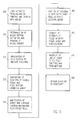
- the control elements of the module 170 control the system 10 in accordance with the procedure shown in pseudocode form in Appendix B. The process by which a data entry field is caused to replicate is further shown in the flow diagram of Figure 5.
- the data entry fields bearing the data descriptors "Preposition” and “Cardinality” are shown as being selected for replication in Figure 2.
- the user operates the mouse 60 to position a mouse pointer 145 over the pushbutton 143 positioned adjacently below the entry fields.
- Replication is activated by pressing a button on the mouse.
- This action is illustrated at step 300 of the flow diagram of Figure 5 and represents the commencement of execution of a data field replication operation.
- a pushbutton activation determining element 180 controls the processor 20 to continuously sample an input from the mouse 60 to compare the mouse pointer location with the position of entry fields and pushbuttons defined in the display.
- the processor 20 is controlled to determine whether the mouse pointer is within the rectangle position of a pushbutton, as described by an origin and rectangle.
- the control information provided by the pushbutton activation determining element 180 for the pushbutton 143 (“Button at: 3") is shown in pseudocode form at line 500 of Appendix B, and is represented by process step 310 in Figure 5. It is understood that equivalent code underlies the other pushbuttons in the data entry block 140. If the mouse pointer 145 is within the pushbutton 143, and the user has depressed a mouse button ("clicked"), a pushbutton highlighting element 190 controls the processor 20 to change the color of the pushbutton 143.
- the control information provided by the pushbutton highlighting element 190 is shown in pseudocode form at lines 1000-1010 of Appendix B, and is represented by process step 320 in Figure 5.
- a display repositioning element 200 controls the processor 20 to compare the postitions of the labels, entry fields and pushbuttons in the display with the position of the selected pushbutton. All display elements positioned above the selected pushbutton, including the data entry field to be replicated, are moved upwardly by adding a constant value to the row number of the object's location.
- the control information provided to the processor 20 by the display repositioning element 200 is shown in pseudocode form at lines 1020-1060 of Appendix B, and is represented by process steps 330 and 340 in Figure 5.
- a data entry field replication element 210 controls the processor 20 to add a new entry field, or group of entry fields, to the display.
- the entry fields to be replicated are determined by the application.
- the activated pushbutton causes a replication of the two entry fields 141 and 142 that were above and to the right of the pushbutton in the original display.
- the new entry fields 147 and 148 in Figure 4 are added to the array in a row adjacently above the pushbutton pressed.
- the net result, when the display is refreshed/redisplayed, is an upward shift of all items above the selected pushbutton and an insertion of new entry fields in the space provided by the shift.
- the control information provided by the data entry field replication element 210 is shown in pseudocode form at lines 1070-1090 of Appendix B, and is represented by process step 350 in Figure 5.
- an entry field position storage element 230 controls the processor 20 to store the contents of all filled-in data entry fields repositioned as a result of the replication procedure, along with the new position locations. This information may be conventiently stored in the volatile storage device 160.
- the control information provided by the position storage element 220 is shown in pseudocode form at line 1100 of Appendix B, and is represented by process step 360 in Figure 5.
- a re-display element 230 provides control information to the processor 20 to redisplay all labels, entry fields, field contents and pushbuttons in the display.
- the control information provided by the redisplay element 230 is shown in pseudocode form at line 1110 of Appendix B, and is represented by process step 370 in Figure 5.
- the replication process is completed in accordance with process step 380 in Figure 5 by scrolling the display window as necessary.
- the user is provided with a form which maintains its initial structure, but which is dynamically extendable by virtue of the user's ability to replicate one or more data entry fields.
- the system allows direct manipulation by using a pointer-actuated pushbutton icon that serves both as a visual indicator that a data entry field can be replicated and as a input for replicating the entry field in an indicated direction. As shown in Figures 2 and 4, the direction of expansion is indicated by the placement of the pushbutton. If the pushbutton is placed below an entry field, one or more new entry fields are created and positioned downwardly from the (upwardly repositioned) initial field(s).
- pushbuttons may be positioned to replicate fields individually and in groups.
- the pushbutton 143 shown as being activated in Figure 2 replicates the two data fields 141 and 142 above and to the right of the pushbutton 143, and corresponding to the label "Children”
- activation of the lower left hand pushbutton 149 would replicate all of the four data fields 151, 152, 141 and 142 corresponding to the "Children” label. This allows the user to implement nested replications to any desired level of nesting, with each replicated data item being treated as a separate object.
- An additional control mechanism for adding data entry fields is to use a pull down menu.
- control functionality may be further provided for deleting data entry fields added by replication (but not the initial data fields).
- These control functions are implemented in the display 410 of Figures 6 and 7.
- the display 410 is similar in many respects to the display 110 of Figures 2 and 4.
- the display 410 thus includes a title block 420, a command menu bar 430 and a data entry block 440.
- a pull-down menu 450 may be activated for data field replication. To add a data entry field using a pull down menu, the user selects an entry field to be replicated by pointing to the entry field with the mouse and clicking the mouse button. This highlights the entry field.
- Entry field duplication is then performed in accordance with the process of Figure 5, with several exceptions. These exceptions result from the fact that the use of the menu 450 for entry field replication requires the selection of a data entry field and not a pushbutton, and because menu-based selection permits the embedding of new entry fields in an existing entry field stack. This differs from the pushbutton control method wherein new entry fields can only be added to the end of an entry field stack. Thus, in the process steps shown in Figure 5, the use of the pull-down menu 450 for entry field replication results in the selected entry field becoming the reference point for shifting entry fields, labels and pushbuttons, rather than a selected pushbutton.
- Controls used to remove entry fields can be implemented by either a remove button 460 with associated minus (-) sign, as shown in Figure 6, or by selecting and highlighting the field to be removed and requesting the "Remove field" action 452 shown in the pull-down menu 450 of Figure 7.
- the pushbutton control method removes the last entry on the entry field stack while the selection method permits selecting entry fields anywhere in the stack other than the initial entry fields. In all cases, the initial entry fields are not removed.
- the entry field removal process works in similar fashion except that the origins for the locations of items above the deleted field are shifted downwardly by subtracting rather than adding units to the y coordinate.
- control system provided by the GUI data control structure could be located within the applications module 80, although it is generally desirable that this system be located to provide input/ouput and graphical user interface services for all applications.
Description
the data processing system being characterised by:
the method comprising the steps of:


Claims (8)
- A data processing system including a video display terminal (40), mouse means (60) for positioning a cursor on the video display terminal and providing control inputs to said system, and graphical user interface means (100) for representing a document on the video display terminal, said document having at least one data field for text entry or display,
the data processing system being characterised by:means for generating a symbol (143) on said document representation associated with one or more data fields (141) therein; andreplicating means (170) responsive to the cursor being positioned at said symbol and to a replicating control input from said mouse means for replicating the one or more data fields associated with the symbol. - The data processing system of claim 1 further including means (190) for modifying the color of the symbol in response to the cursor being positioned at said symbol.
- The data processing system of claim 1 or 2, wherein said document representation includes plural display elements and said system further includes means (200) responsive to replication of said data field for repositioning one or more of said display elements in a predetermined direction from said symbol.
- The data processing system of claim 3 further including means (220) responsive to replication of said data field for storing positions of said one or more display elements.
- The data processing system of claim 4 further including means (230) responsive to the storage of said positions for displaying said display elements at corresponding positions in said document representation.
- The data processing system of any preceding claim, wherein the replicating means includes means for displaying a menu (450) including a replication option (451), said replicating means being responsive to user selection of said replication option to perform the replication.
- The data processing system of any preceding claim, further including:means for generating a second symbol (460) on said document representation paired with the first symbol and associated with the same one or more data fields as the first symbol; anddeleting means responsive to the cursor being positioned at said second symbol and to a deleting control input from said mouse means for deleting replicated versions of the one or more data fields associated with the symbols.
- A method for controlling input/ouput from a data processing system including a video display terminal (40), mouse means (60) for positioning a cursor on the video display terminal and providing control inputs to said system, and graphical user interface means (100) for representing a document on the video display terminal, said document having at least one data field for text entry or display,
the method comprising the steps of:generating a symbol (143) on said document representation associated with on or more data fields (141) therein; andreplicating one or more data fields in response to the cursor being positioned at the associated symbol and to to a replicating control input from the mouse means.
Applications Claiming Priority (2)
| Application Number | Priority Date | Filing Date | Title |
|---|---|---|---|
| US78935391A | 1991-11-08 | 1991-11-08 | |
| US789353 | 1991-11-08 |
Publications (2)
| Publication Number | Publication Date |
|---|---|
| EP0541236A1 EP0541236A1 (en) | 1993-05-12 |
| EP0541236B1 true EP0541236B1 (en) | 1998-04-29 |
Family
ID=25147381
Family Applications (1)
| Application Number | Title | Priority Date | Filing Date |
|---|---|---|---|
| EP92308858A Expired - Lifetime EP0541236B1 (en) | 1991-11-08 | 1992-09-29 | Form definition method |
Country Status (4)
| Country | Link |
|---|---|
| US (2) | US5444841A (en) |
| EP (1) | EP0541236B1 (en) |
| JP (1) | JPH0721754B2 (en) |
| DE (1) | DE69225295D1 (en) |
Families Citing this family (115)
| Publication number | Priority date | Publication date | Assignee | Title |
|---|---|---|---|---|
| US5241464A (en) * | 1990-08-17 | 1993-08-31 | Moore Business Forms, Inc. | Desktop forms order system |
| JPH0721754B2 (en) * | 1991-11-08 | 1995-03-08 | インターナショナル・ビジネス・マシーンズ・コーポレイション | Graphical user interface |
| US5950169A (en) * | 1993-05-19 | 1999-09-07 | Ccc Information Services, Inc. | System and method for managing insurance claim processing |
| JPH0793341A (en) * | 1993-09-27 | 1995-04-07 | Matsushita Electric Ind Co Ltd | Document management device |
| US5530961A (en) * | 1994-04-21 | 1996-06-25 | Janay; Gad | Terminal emulator enhancer with local configurability |
| US5583981A (en) * | 1994-06-28 | 1996-12-10 | Microsoft Corporation | Method and system for changing the size of edit controls on a graphical user interface |
| US5995985A (en) * | 1995-11-16 | 1999-11-30 | Starfish Software, Inc. | Information management system with improved methods and interface for printing data |
| US5872640A (en) * | 1995-11-28 | 1999-02-16 | Cable & Wireless, Inc. | Facsimile form generation system |
| US5768581A (en) * | 1996-05-07 | 1998-06-16 | Cochran; Nancy Pauline | Apparatus and method for selecting records from a computer database by repeatedly displaying search terms from multiple list identifiers before either a list identifier or a search term is selected |
| US6055548A (en) * | 1996-06-03 | 2000-04-25 | Microsoft Corporation | Computerized spreadsheet with auto-calculator |
| US5950168A (en) * | 1996-12-18 | 1999-09-07 | Knowmed Systems | Collapsible flowsheet for displaying patient information in an electronic medical record |
| US6108673A (en) * | 1997-02-25 | 2000-08-22 | International Business Machines Corporation | System for creating a form from a template that includes replication block |
| US5905486A (en) * | 1997-03-03 | 1999-05-18 | International Business Machines Corporation | Mobile client computer programmed to combine cursor, control and input functions |
| US6108661A (en) * | 1997-07-14 | 2000-08-22 | Microsoft Corporation | System for instance customization |
| US6449659B1 (en) | 1997-07-14 | 2002-09-10 | Microsoft Corporation | System for instance customization with application independent programming of controls |
| US6718534B1 (en) | 1997-07-14 | 2004-04-06 | Microsoft Corporation | System for application independent programming of controls |
| US6137488A (en) * | 1997-12-05 | 2000-10-24 | International Business Machines Corporation | System for creating structured fields on electronic forms |
| US6084585A (en) * | 1998-07-29 | 2000-07-04 | International Business Machines Corp. | System for directly accessing fields on electronic forms |
| US6208339B1 (en) | 1998-06-19 | 2001-03-27 | International Business Machines Corporation | User-interactive data entry display system with entry fields having distinctive and changeable autocomplete |
| EP1131759A2 (en) | 1998-11-13 | 2001-09-12 | The Chase Manhattan Bank | System and method for multicurrency and multibank processing over a non-secure network |
| CA2358528C (en) | 1998-12-23 | 2015-04-14 | The Chase Manhattan Bank | System and method for integrating trading operations including the generation, processing and tracking of trade documents |
| JP2002539534A (en) * | 1999-03-08 | 2002-11-19 | サン・マイクロシステムズ・インコーポレイテッド | Method and apparatus for submitting data to an online form system |
| AUPP962599A0 (en) | 1999-04-07 | 1999-04-29 | Liberty Financial Pty Ltd | Application apparatus and method |
| US7068832B1 (en) | 1999-05-11 | 2006-06-27 | The Chase Manhattan Bank | Lockbox imaging system |
| US6476828B1 (en) | 1999-05-28 | 2002-11-05 | International Business Machines Corporation | Systems, methods and computer program products for building and displaying dynamic graphical user interfaces |
| US7340426B1 (en) * | 1999-07-30 | 2008-03-04 | Computer Sciences Corporation | Event-triggered transaction processing for electronic data interchange |
| US7805365B1 (en) | 1999-10-25 | 2010-09-28 | Jpmorgan Chase Bank, N.A. | Automated statement presentation, adjustment and payment system and method therefor |
| US7822656B2 (en) | 2000-02-15 | 2010-10-26 | Jpmorgan Chase Bank, N.A. | International banking system and method |
| US8768836B1 (en) | 2000-02-18 | 2014-07-01 | Jpmorgan Chase Bank, N.A. | System and method for electronic deposit of a financial instrument by banking customers from remote locations by use of a digital image |
| US6678889B1 (en) | 2000-05-05 | 2004-01-13 | International Business Machines Corporation | Systems, methods and computer program products for locating resources within an XML document defining a console for managing multiple application programs |
| US7831508B1 (en) | 2000-06-23 | 2010-11-09 | Jpmorgan Chase Bank, N.A. | System and method for implementing a consolidated application process |
| US7584125B2 (en) | 2000-06-26 | 2009-09-01 | Jpmorgan Chase Bank, N.A. | Electronic check presentment system and method having an item sequence capability |
| US8468071B2 (en) | 2000-08-01 | 2013-06-18 | Jpmorgan Chase Bank, N.A. | Processing transactions using a register portion to track transactions |
| WO2002015098A2 (en) | 2000-08-11 | 2002-02-21 | Loy John J | Trade receivable processing method and apparatus |
| US7206768B1 (en) | 2000-08-14 | 2007-04-17 | Jpmorgan Chase Bank, N.A. | Electronic multiparty accounts receivable and accounts payable system |
| US8015084B1 (en) | 2000-09-06 | 2011-09-06 | Jpmorgan Chase Bank, N.A. | System and method for linked account having sweep feature |
| US7587363B2 (en) | 2000-11-06 | 2009-09-08 | Jpmorgan Chase Bank, N.A. | System and method for optimized funding of electronic transactions |
| AU2002224482A1 (en) | 2000-11-06 | 2002-05-15 | First Usa Bank, N.A. | System and method for selectable funding of electronic transactions |
| US20040143553A1 (en) * | 2000-12-01 | 2004-07-22 | Torget John W. | System and method for remotely generating instruments |
| US20020103826A1 (en) * | 2001-01-29 | 2002-08-01 | Banta Corporation | System and method for creating documents populated with variable data |
| US8805739B2 (en) | 2001-01-30 | 2014-08-12 | Jpmorgan Chase Bank, National Association | System and method for electronic bill pay and presentment |
| US7158250B2 (en) * | 2001-02-16 | 2007-01-02 | Canon Kabushiki Kaisha | Information processing apparatus, information processing system, information processing method, coversheet generating method, program, and storage medium |
| US7539747B2 (en) | 2001-03-14 | 2009-05-26 | Microsoft Corporation | Schema-based context service |
| US7302634B2 (en) | 2001-03-14 | 2007-11-27 | Microsoft Corporation | Schema-based services for identity-based data access |
| US7024662B2 (en) * | 2001-03-14 | 2006-04-04 | Microsoft Corporation | Executing dynamically assigned functions while providing services |
| US8069419B2 (en) * | 2001-04-18 | 2011-11-29 | Sas Institute Inc. | Graphical user interface check-list button control and method |
| US7401048B2 (en) | 2001-06-01 | 2008-07-15 | Jpmorgan Chase Bank, N.A. | System and method for trade settlement tracking and relative ranking |
| US7963899B2 (en) * | 2001-07-13 | 2011-06-21 | The Proctor & Gamble Company | Continuous in-line pleating apparatus and process |
| US7822684B2 (en) | 2001-10-05 | 2010-10-26 | Jpmorgan Chase Bank, N.A. | Personalized bank teller machine |
| US7627521B1 (en) | 2002-01-15 | 2009-12-01 | Jpmorgan Chase Bank, N.A. | System and method for processing mircotransactions |
| US20030137495A1 (en) * | 2002-01-22 | 2003-07-24 | Palm, Inc. | Handheld computer with pop-up user interface |
| US7899753B1 (en) | 2002-03-25 | 2011-03-01 | Jpmorgan Chase Bank, N.A | Systems and methods for time variable financial authentication |
| JP2003295969A (en) * | 2002-03-29 | 2003-10-17 | Fujitsu Ltd | Automatic information input program |
| US7437327B2 (en) | 2002-05-24 | 2008-10-14 | Jp Morgan Chase Bank | Method and system for buyer centric dispute resolution in electronic payment system |
| US7689482B2 (en) | 2002-05-24 | 2010-03-30 | Jp Morgan Chase Bank, N.A. | System and method for payer (buyer) defined electronic invoice exchange |
| US20030220863A1 (en) | 2002-05-24 | 2003-11-27 | Don Holm | System and method for varying electronic settlements between buyers and suppliers with dynamic discount terms |
| US7519560B2 (en) | 2002-05-24 | 2009-04-14 | Jpmorgan Chase Bank, N.A. | System and method for electronic authorization of batch checks |
| US7284197B2 (en) * | 2002-06-28 | 2007-10-16 | Microsoft Corporation | Schema-based services for identity-based data access to application settings data |
| US9886309B2 (en) | 2002-06-28 | 2018-02-06 | Microsoft Technology Licensing, Llc | Identity-based distributed computing for device resources |
| US7099918B2 (en) * | 2002-08-16 | 2006-08-29 | Sas Institute Inc. | Web-based form validation system and method |
| US7769650B2 (en) | 2002-12-03 | 2010-08-03 | Jp Morgan Chase Bank | Network-based sub-allocation systems and methods for swaps |
| US7511852B2 (en) * | 2003-03-10 | 2009-03-31 | Toshiba Corporation | System and method for variable copying or reproducing a plurality of documents |
| US10311412B1 (en) | 2003-03-28 | 2019-06-04 | Jpmorgan Chase Bank, N.A. | Method and system for providing bundled electronic payment and remittance advice |
| US8630947B1 (en) | 2003-04-04 | 2014-01-14 | Jpmorgan Chase Bank, N.A. | Method and system for providing electronic bill payment and presentment |
| US7613656B2 (en) | 2003-08-11 | 2009-11-03 | Jp Morgan Chase Bank | Coupon payment system |
| US7792717B1 (en) | 2003-10-31 | 2010-09-07 | Jpmorgan Chase Bank, N.A. | Waterfall prioritized payment processing |
| US7702577B1 (en) | 2003-11-06 | 2010-04-20 | Jp Morgan Chase Bank, N.A. | System and method for conversion of initial transaction to final transaction |
| US7814003B2 (en) | 2003-12-15 | 2010-10-12 | Jp Morgan Chase | Billing workflow system for crediting charges to entities creating derivatives exposure |
| US10332190B1 (en) | 2004-01-30 | 2019-06-25 | Jpmorgan Chase Bank, N.A. | System and method for trade payment exchange |
| US20100287092A1 (en) * | 2004-02-25 | 2010-11-11 | Bank One, Delaware National Association | Method and system for real estate loan administration |
| US7380707B1 (en) | 2004-02-25 | 2008-06-03 | Jpmorgan Chase Bank, N.A. | Method and system for credit card reimbursements for health care transactions |
| US8554673B2 (en) | 2004-06-17 | 2013-10-08 | Jpmorgan Chase Bank, N.A. | Methods and systems for discounts management |
| US8121944B2 (en) | 2004-06-24 | 2012-02-21 | Jpmorgan Chase Bank, N.A. | Method and system for facilitating network transaction processing |
| US8290862B2 (en) | 2004-07-23 | 2012-10-16 | Jpmorgan Chase Bank, N.A. | Method and system for expediting payment delivery |
| US8290863B2 (en) | 2004-07-23 | 2012-10-16 | Jpmorgan Chase Bank, N.A. | Method and system for expediting payment delivery |
| US7818342B2 (en) * | 2004-11-12 | 2010-10-19 | Sap Ag | Tracking usage of data elements in electronic business communications |
| US7711676B2 (en) * | 2004-11-12 | 2010-05-04 | Sap Aktiengesellschaft | Tracking usage of data elements in electronic business communications |
| US7865519B2 (en) * | 2004-11-17 | 2011-01-04 | Sap Aktiengesellschaft | Using a controlled vocabulary library to generate business data component names |
| US7983468B2 (en) | 2005-02-09 | 2011-07-19 | Jp Morgan Chase Bank | Method and system for extracting information from documents by document segregation |
| US7360686B2 (en) * | 2005-05-11 | 2008-04-22 | Jp Morgan Chase Bank | Method and system for discovering significant subsets in collection of documents |
| US7822682B2 (en) | 2005-06-08 | 2010-10-26 | Jpmorgan Chase Bank, N.A. | System and method for enhancing supply chain transactions |
| US7676409B1 (en) * | 2005-06-20 | 2010-03-09 | Jpmorgan Chase Bank, N.A. | Method and system for emulating a private label over an open network |
| US8301529B1 (en) | 2005-11-02 | 2012-10-30 | Jpmorgan Chase Bank, N.A. | Method and system for implementing effective governance of transactions between trading partners |
| US7716255B2 (en) * | 2005-11-30 | 2010-05-11 | Sap Ag | Modeling a data element |
| US20070240062A1 (en) * | 2006-04-07 | 2007-10-11 | Christena Jennifer Y | Method and System for Restricting User Operations in a Graphical User Inerface Window |
| US7953804B2 (en) * | 2006-06-02 | 2011-05-31 | Research In Motion Limited | User interface for a handheld device |
| US7734545B1 (en) | 2006-06-14 | 2010-06-08 | Jpmorgan Chase Bank, N.A. | Method and system for processing recurring payments |
| US7916925B2 (en) | 2007-02-09 | 2011-03-29 | Jpmorgan Chase Bank, N.A. | System and method for generating magnetic ink character recognition (MICR) testing documents |
| US8078568B2 (en) * | 2007-06-25 | 2011-12-13 | Sap Ag | Properties of data elements |
| US8086646B2 (en) * | 2007-07-20 | 2011-12-27 | Sap Ag | Scheme-based identifier |
| US8762270B1 (en) | 2007-08-10 | 2014-06-24 | Jpmorgan Chase Bank, N.A. | System and method for providing supplemental payment or transaction information |
| US8280755B2 (en) * | 2007-10-30 | 2012-10-02 | Sap Ag | Context-specific modeling of collaborative business process |
| US8788281B1 (en) | 2007-12-03 | 2014-07-22 | Jp Morgan Chase Bank, N.A. | System and method for processing qualified healthcare account related financial transactions |
| US7766244B1 (en) | 2007-12-31 | 2010-08-03 | Jpmorgan Chase Bank, N.A. | System and method for processing transactions using a multi-account transactions device |
| US8622308B1 (en) | 2007-12-31 | 2014-01-07 | Jpmorgan Chase Bank, N.A. | System and method for processing transactions using a multi-account transactions device |
| US9483755B2 (en) | 2008-03-04 | 2016-11-01 | Apple Inc. | Portable multifunction device, method, and graphical user interface for an email client |
| US7979477B2 (en) * | 2008-03-15 | 2011-07-12 | Microsoft Corporation | Placeholder control for updating database object |
| US20090241055A1 (en) * | 2008-03-21 | 2009-09-24 | Augustine Nancy L | Systems and methods for side by side display of data modification |
| JP5366178B2 (en) * | 2008-05-22 | 2013-12-11 | インターナショナル・ビジネス・マシーンズ・コーポレーション | Method for supporting input to input items of web page, computer program, and terminal |
| US8112355B1 (en) | 2008-09-05 | 2012-02-07 | Jpmorgan Chase Bank, N.A. | Method and system for buyer centric dispute resolution in electronic payment system |
| US8391584B2 (en) | 2008-10-20 | 2013-03-05 | Jpmorgan Chase Bank, N.A. | Method and system for duplicate check detection |
| US9092447B1 (en) | 2008-10-20 | 2015-07-28 | Jpmorgan Chase Bank, N.A. | Method and system for duplicate detection |
| US8312370B2 (en) * | 2009-03-10 | 2012-11-13 | Lsi Corporation | System and method of hardware-assisted assembly of documents |
| US8447641B1 (en) | 2010-03-29 | 2013-05-21 | Jpmorgan Chase Bank, N.A. | System and method for automatically enrolling buyers into a network |
| US8589288B1 (en) | 2010-10-01 | 2013-11-19 | Jpmorgan Chase Bank, N.A. | System and method for electronic remittance of funds |
| US8543503B1 (en) | 2011-03-30 | 2013-09-24 | Jpmorgan Chase Bank, N.A. | Systems and methods for automated invoice entry |
| US8543504B1 (en) | 2011-03-30 | 2013-09-24 | Jpmorgan Chase Bank, N.A. | Systems and methods for automated invoice entry |
| USD678653S1 (en) | 2012-07-19 | 2013-03-19 | Jpmorgan Chase Bank, N.A. | Drive-up financial transaction machine |
| US9250793B2 (en) * | 2012-12-21 | 2016-02-02 | Sap Se | Interface management systems and methods |
| US9158433B1 (en) * | 2013-03-04 | 2015-10-13 | Ca, Inc. | Graphical user interface text selection and processing in client applications employing a screen-at-a-time based communication protocol |
| USD690074S1 (en) | 2013-03-13 | 2013-09-17 | Jpmorgan Chase Bank, N.A. | Financial transaction machine |
| US9058626B1 (en) | 2013-11-13 | 2015-06-16 | Jpmorgan Chase Bank, N.A. | System and method for financial services device usage |
| US9898162B2 (en) | 2014-05-30 | 2018-02-20 | Apple Inc. | Swiping functions for messaging applications |
| WO2016036509A1 (en) | 2014-09-02 | 2016-03-10 | Apple Inc. | Electronic mail user interface |
| US20220358135A1 (en) * | 2021-05-06 | 2022-11-10 | Hitachi, Ltd. | System and method for data and data processing management |
Family Cites Families (10)
| Publication number | Priority date | Publication date | Assignee | Title |
|---|---|---|---|---|
| US4658366A (en) * | 1984-08-09 | 1987-04-14 | Posh David R | Methods and apparatus for accurately completing pre-printed forms |
| US4646250A (en) * | 1984-10-18 | 1987-02-24 | International Business Machines Corp. | Data entry screen |
| US4982344A (en) * | 1988-05-18 | 1991-01-01 | Xerox Corporation | Accelerating link creation |
| US4896291A (en) * | 1988-05-20 | 1990-01-23 | International Business Machines Corporation | Valuator menu for use as a graphical user interface tool |
| US5144693A (en) * | 1988-12-30 | 1992-09-01 | Chipsoft Ca Corp. | Method and apparatus for generic form generation |
| US5208906A (en) * | 1988-12-30 | 1993-05-04 | Chipsoft Ca, Corp. | Method and apparatus for representing bordered areas of a generic form with records |
| US5165015A (en) * | 1989-09-25 | 1992-11-17 | Reliance Electric Industrial Company | Electronic template system and method |
| US5140139A (en) * | 1989-11-13 | 1992-08-18 | Cognitronics Corporation | Preparing mark/read documents with markable boxes and locating the boxes from the document scan data |
| EP0451485A3 (en) * | 1990-04-11 | 1992-12-30 | International Business Machines Corporation | A form authoring toolkit |
| JPH0721754B2 (en) * | 1991-11-08 | 1995-03-08 | インターナショナル・ビジネス・マシーンズ・コーポレイション | Graphical user interface |
-
1992
- 1992-08-19 JP JP4220416A patent/JPH0721754B2/en not_active Expired - Lifetime
- 1992-09-29 EP EP92308858A patent/EP0541236B1/en not_active Expired - Lifetime
- 1992-09-29 DE DE69225295T patent/DE69225295D1/en not_active Expired - Lifetime
-
1994
- 1994-04-26 US US08/233,894 patent/US5444841A/en not_active Expired - Fee Related
-
1995
- 1995-05-18 US US08/444,326 patent/US5544285A/en not_active Expired - Fee Related
Also Published As
| Publication number | Publication date |
|---|---|
| JPH0721754B2 (en) | 1995-03-08 |
| US5444841A (en) | 1995-08-22 |
| DE69225295D1 (en) | 1998-06-04 |
| US5544285A (en) | 1996-08-06 |
| JPH05224859A (en) | 1993-09-03 |
| EP0541236A1 (en) | 1993-05-12 |
Similar Documents
| Publication | Publication Date | Title |
|---|---|---|
| EP0541236B1 (en) | Form definition method | |
| US5450538A (en) | Graphical user interface control for expansion and re-sizing of data fields in forms | |
| EP1005681B1 (en) | Browser for hierarchical structures | |
| US8522159B2 (en) | System for accessing a large number of menu items using a zoned menu bar | |
| US5515496A (en) | Computer system with direct manipulation interface and method of operating same | |
| US6643824B1 (en) | Touch screen region assist for hypertext links | |
| US5463727A (en) | Window selection method and system for an interactive display | |
| US5559948A (en) | Apparatus and method for manipulating an object in a computer system graphical user interface | |
| EP0328831B1 (en) | Entry selection method using a keyboard | |
| US5305435A (en) | Computer windows management system and method for simulating off-screen document storage and retrieval | |
| US5604861A (en) | Method and apparatus for improved notebook control in a data procesing system | |
| EP0733964B1 (en) | Elision based presentation of ordered data | |
| US6636244B1 (en) | Pointing device selection method | |
| JPH0756839A (en) | Operating method of processor-based apparatus | |
| JPH0756841A (en) | Operating method of processor-based apparatus | |
| JPH04337798A (en) | Data processing system with display window | |
| EP0451485A2 (en) | A form authoring toolkit | |
| EP0325443B1 (en) | Help facility shared by a plurality of applications | |
| JP2000172398A (en) | Interface control for performing switching among display areas on display device | |
| US5796383A (en) | Method and system for presenting contents of a container object within a graphical user interface in a data processing system | |
| US8793589B2 (en) | Melded user interfaces | |
| JP3712749B2 (en) | Window display processing method in information processing equipment | |
| EP0541237A1 (en) | Data entry field modification in a graphical user interface | |
| JPH0962478A (en) | Computer system | |
| AU2002301073B2 (en) | Browser For Hierarichial Structures |
Legal Events
| Date | Code | Title | Description |
|---|---|---|---|
| PUAI | Public reference made under article 153(3) epc to a published international application that has entered the european phase |
Free format text: ORIGINAL CODE: 0009012 |
|
| AK | Designated contracting states |
Kind code of ref document: A1 Designated state(s): DE FR GB |
|
| 17P | Request for examination filed |
Effective date: 19930918 |
|
| GRAG | Despatch of communication of intention to grant |
Free format text: ORIGINAL CODE: EPIDOS AGRA |
|
| 17Q | First examination report despatched |
Effective date: 19970606 |
|
| GRAG | Despatch of communication of intention to grant |
Free format text: ORIGINAL CODE: EPIDOS AGRA |
|
| GRAH | Despatch of communication of intention to grant a patent |
Free format text: ORIGINAL CODE: EPIDOS IGRA |
|
| GRAH | Despatch of communication of intention to grant a patent |
Free format text: ORIGINAL CODE: EPIDOS IGRA |
|
| GRAA | (expected) grant |
Free format text: ORIGINAL CODE: 0009210 |
|
| AK | Designated contracting states |
Kind code of ref document: B1 Designated state(s): DE FR GB |
|
| PG25 | Lapsed in a contracting state [announced via postgrant information from national office to epo] |
Ref country code: FR Free format text: LAPSE BECAUSE OF FAILURE TO SUBMIT A TRANSLATION OF THE DESCRIPTION OR TO PAY THE FEE WITHIN THE PRESCRIBED TIME-LIMIT Effective date: 19980429 |
|
| REF | Corresponds to: |
Ref document number: 69225295 Country of ref document: DE Date of ref document: 19980604 |
|
| PG25 | Lapsed in a contracting state [announced via postgrant information from national office to epo] |
Ref country code: DE Free format text: LAPSE BECAUSE OF FAILURE TO SUBMIT A TRANSLATION OF THE DESCRIPTION OR TO PAY THE FEE WITHIN THE PRESCRIBED TIME-LIMIT Effective date: 19980730 |
|
| EN | Fr: translation not filed | ||
| PG25 | Lapsed in a contracting state [announced via postgrant information from national office to epo] |
Ref country code: GB Free format text: LAPSE BECAUSE OF NON-PAYMENT OF DUE FEES Effective date: 19980929 |
|
| PLBE | No opposition filed within time limit |
Free format text: ORIGINAL CODE: 0009261 |
|
| STAA | Information on the status of an ep patent application or granted ep patent |
Free format text: STATUS: NO OPPOSITION FILED WITHIN TIME LIMIT |
|
| 26N | No opposition filed | ||
| GBPC | Gb: european patent ceased through non-payment of renewal fee |
Effective date: 19980929 |