EP0540231A2 - Coded modulation with unequal error protection - Google Patents
Coded modulation with unequal error protection Download PDFInfo
- Publication number
- EP0540231A2 EP0540231A2 EP19920309608 EP92309608A EP0540231A2 EP 0540231 A2 EP0540231 A2 EP 0540231A2 EP 19920309608 EP19920309608 EP 19920309608 EP 92309608 A EP92309608 A EP 92309608A EP 0540231 A2 EP0540231 A2 EP 0540231A2
- Authority
- EP
- European Patent Office
- Prior art keywords
- symbols
- bits
- supersymbols
- channel
- constellation
- Prior art date
- Legal status (The legal status is an assumption and is not a legal conclusion. Google has not performed a legal analysis and makes no representation as to the accuracy of the status listed.)
- Granted
Links
Images


Classifications
-
- H—ELECTRICITY
- H04—ELECTRIC COMMUNICATION TECHNIQUE
- H04L—TRANSMISSION OF DIGITAL INFORMATION, e.g. TELEGRAPHIC COMMUNICATION
- H04L27/00—Modulated-carrier systems
- H04L27/32—Carrier systems characterised by combinations of two or more of the types covered by groups H04L27/02, H04L27/10, H04L27/18 or H04L27/26
- H04L27/34—Amplitude- and phase-modulated carrier systems, e.g. quadrature-amplitude modulated carrier systems
- H04L27/3405—Modifications of the signal space to increase the efficiency of transmission, e.g. reduction of the bit error rate, bandwidth, or average power
- H04L27/3416—Modifications of the signal space to increase the efficiency of transmission, e.g. reduction of the bit error rate, bandwidth, or average power in which the information is carried by both the individual signal points and the subset to which the individual points belong, e.g. using coset coding, lattice coding, or related schemes
-
- H—ELECTRICITY
- H04—ELECTRIC COMMUNICATION TECHNIQUE
- H04L—TRANSMISSION OF DIGITAL INFORMATION, e.g. TELEGRAPHIC COMMUNICATION
- H04L27/00—Modulated-carrier systems
- H04L27/32—Carrier systems characterised by combinations of two or more of the types covered by groups H04L27/02, H04L27/10, H04L27/18 or H04L27/26
- H04L27/34—Amplitude- and phase-modulated carrier systems, e.g. quadrature-amplitude modulated carrier systems
- H04L27/3488—Multiresolution systems
Definitions
- the present invention relates to the transmission of digital data including, particularly, the transmission of digital data which represents television (TV) signals.
- HDTV high definition television
- SNR signal-to-noise ratio
- a first one of the aforementioned data streams carries components of the overall television signal which are regarded as the most important--for example, the audio, the framing information, and the vital potions of the video information--and that data stream is mapped such that its data elements have the lowest probability of channel-induced error.
- a second one of the data streams carries components of the overall television signal which are regarded as less important than those of the first data stream and that data stream is mapped such that its data elements have a probability of channel-induced error that is not as low as those of the first data stream.
- the symbols in a predetermined 2N-dimensional channel symbol constellation, N ⁇ 1 are divided into groups, each of which is referred to as a "supersymbol.”
- a predetermined number of the most important data elements are channel encoded, and the resulting channel coded data elements identify a particular one of the supersymbols.
- the remaining data elements which may also be channel encoded, are used to select for transmission a particular symbol from the identified supersymbol.
- the approach as thus far described is similar in a general way to conventional coded modulation schemes in that the latter also divide the channel symbols into groups, typically referred to as "subsets.”
- the subsets are formed under the constraint that the minimum Euclidean distance (hereinafter referred to as the "minimum distance") between the symbols in a subset is greater than the minimum distance between the symbols in the constellation as a whole.
- the minimum distance between the symbols of a supersymbol is the same as the minimum distance between the symbols in the constellation as a whole.
- This distance property allows for greater amount of noise immunity for the most important data elements than for the other data elements, that immunity being optimized by keeping the minimum distance between supersymbols as large as possible--usually greater than the minimum distance between the symbols of the constellation.
- the supersymbols are defined, it is possible to design codes for the most important data elements based on the distances between the supersymbols, i.e., as though each supersymbol were a conventional symbol in a conventional constellation. This being so, a particular degree of noise immunity can be achieved for the most important data elements that is greater than what can be achieved for the other data elements.
- multi-level coding is used to code the data elements of at least one of the data streams that are input to the channel mapping step.
- multi-level coding can be used to code the data elements which ultimately determine the supersymbol selection.
- it may be used to code the data elements which determine the selection of a particular symbol from within a selected supersymbol.
- multi-level coding can be used for both streams. The particular way in which the multi-level coding is used will depend on the requirements of any particular application in terms of the degree of error protection desired to be afforded to any particular class of the data being coded.
- Multi-level coding per se is a technique already known in the prior art.
- data elements to be coded are divided into two or more substreams.
- Each of one or more of the substreams is then individually redundancy coded using a code of any desired type.
- the prior art does not encompass the teaching, lying at the heart of the present invention, that multi-level coding can be advantageously used to code one or more of the data streams of an overall unequal-error-protection signaling scheme.
- television (TV) signal source 101 generates an analog video signal representing picture information or "intelligence," which signal is passed on to source encoder 104.
- the latter generates a digital signal comprised of data elements in which at least one subset of the data elements represents a portion of the information, or intelligence, that is more important than the portion of the information, or intelligence, represented by the rest of the data elements.
- each data element is a data bit, with an average m+k information bits being generated for each of a succession of symbol intervals.
- the symbol intervals are comprised of N signaling intervals, where 2N is the number of dimensions of the constellation (as described below).
- the signaling intervals have duration of T seconds and, accordingly, the symbol intervals each have a duration of NT seconds.
- the bits within the stream of m bits per symbol interval, appearing on lead 105 are more important than the bits within the stream of k bits per symbol interval, appearing on lead 106.
- the bits on leads 105 and 106 are independently scrambled in scramblers 110 and 111, which respectively output m and k parallel bits on leads 112 and 113.
- Scamblers 110 and 111 may be assumed to perform a parallel-to-serial conversion on their respective input bits prior to scrambling and a serial-to-parallel conversion at their outputs.
- the signal is then channel mapped.
- the respective groups of bits on leads 112 and 113 are extended to channel encoders 114 and 115 which generate, for each symbol interval, respective expanded groups of r and p bits on leads 121 and 122, where r > m and p > k.
- the values of those bits jointly identify a particular channel symbol of a predetermined constellation of channel symbols (such as the constellation of FIG. 4 as described in detail hereinbelow).
- Complex plane coordinates of the identified channel symbol are output by constellation mapper 131, illustratively realized as a lookup table or as a straightforward combination of logic elements.
- Conventional pass-band shaping and television modulation are then performed by passband shaper 141 and television modulator 151, respectively.
- the resultant analog signal is then broadcast via antenna 152 over a communication channel, in this case a free-space channel.
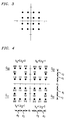
- FIG. 3 depicts a standard two-dimensional data transmission constellation of the type conventionally used in digital radio and voiceband data transmission systems.
- quadrature-amplitude modulation (QAM)--data words each comprised of four information bits are each mapped into one of 16 possible two-dimensional channel symbols.
- Each channel symbol has an in-phase, or I, coordinate on the horizontal axis and has a quadrature-phase, or Q, coordinate on the vertical axis.
- the channel symbol coordinates are ⁇ 1 or ⁇ 3 so that the distance between each symbol and each of the symbols that are horizontally or vertically adjacent to it is the same for all symbols --that distance being "2".
- the distance between each symbol and each of the symbols that are horizontally or vertically adjacent to it is the same for all symbols --that distance being "2".
- the constellation used in the transmitter of FIG. 1 is illustratively the two-dimensional 32-symbol constellation shown in FIG. 4.
- the symbols in the signal constellation are divided into groups referred to as "supersymbols.”
- the points in the four quadrants constitute respective supersymbols, as denoted by a box enclosing each group.
- the four supersymbols are thus ⁇ 00, ⁇ 01, ⁇ 10, and ⁇ 11.
- the partitioning of the constellation is such that the minimum distance between the symbols of a supersymbol--that distance being denoted as d 2 in FIG. 4--is the same as the minimum distance between the symbols in the constellation as a whole.
- d 2 the minimum distance between the symbols in the constellation as a whole.
- d 1 the minimum distance between the supersymbols.
- the parameter d 1 is given by the minimum of the distances between all the pairs of supersymbols, with the distance between any pair of supersymbols being the minimum distance between any symbol of one of the pair of supersymbols and any symbol of the other.
- a coded modulation scheme can now be constructed for the most important bits as though the four supersymbols were four conventional symbols in a conventional constellation.
- the four supersymbols are partitioned, as is conventional, into a predetermined number of subsets. In this case, there are two subsets, where the value of b 3 denotes which subset each of the supersymbols belongs to.
- one subset referred to as subset "0” comprises supersymbols ⁇ 00 and ⁇ 10 and the other, referred to as subset "1”, comprises supersymbols ⁇ 01 and ⁇ 11.
- An appropriate code is used to encode the most important input bits to generate a stream of coded output bits which a) define a sequence of these subsets and b) for each subset of the sequence, select a particular supersymbol within that subset. The less important bits are then used to select for transmission a particular symbol from each of the thus-selected supersymbols. In this example, as already seen, this latter selection also involves the use of coded modulation.
- At least one of the channel encoders implements a multi-level code.
- a multi-level code is one in which the data elements--in this embodiment, bits--to be coded are divided into two or more substreams. Each of one or more of the substreams is then individually redundancy coded using a code of any desired type. The individual encoded substreams--along with any substreams that were left uncoded--form the output of the multi-level code.
- Encoder 114 implements a two-level code and, as such, includes two coders--coders 1141 and 1142.
- the output of converter 1144 comprises two substreams of bits. In one substream, the bits are provided in parallel groups of seven to coder 1141. In the other substream, the bits are provided in parallel groups of six to coder 1142.
- coder 1141 For every group of seven input bits, coder 1141 generates eight output bits which are applied to 8-bit buffer 1147. At the same time, for every group of six input bits, coder 1142 generates eight output bits which are applied to 8-bit buffer 1148.
- the contents of buffers 1147 and 1148 are read out synchronously in such a way that a pair of bits--one from each of the two buffers--is provided on lead 121 for each symbol interval. These bits are the aforementioned bits b 3 and b 4.
- the former identifies one of the two subsets "0" and "1” and the other identifies one of the two supersymbols from the identified subset, the two bits b3 and b 4 thus identifying one of the four supersymbols ⁇ 00, ⁇ 01, ⁇ 10 and ⁇ 11.
- the output of converter 1154 comprises three substreams of bits. In one substream, the bits are provided in parallel groups of seven to coder 1151.
- the bits are provided in parallel groups of six to coder 1152.
- the bits are provided in parallel groups of four to coder 1153.
- coder 1151 generates eight output bits which are applied to 8-bit buffer 1157.
- coder 1152 generates eight output bits which are applied to 8-bit buffer 1158.
- coder 1153 generates eight output bits which are applied to 8-bit buffer 1159.
- buffers 1157, 1158 and 1159 are read out synchronously in such a way that three bits--one from each of the three buffers--are provided on lead 122 for each symbol interval. These three bits--denoted b 2, b 1 and b 0-- select a particular symbol from the supersymbol identified at the output of encoder 114. To this end, each of the symbols in the constellation is labelled with a three-bit label as shown in FIG. 4. These three bits are, in fact, the aforementioned bits b 2, b 1 and b 0.
- each supersymbol are partitioned at a first level of partitioning into two subsets.
- Each subset is comprised of four symbols as denoted by the labelled b 0 value.
- one subset is comprised of the four symbols denoted 000, 010, 100 and 110 and the other subset is comprised of the four symbols denoted 001, 011, 101 and 111.
- the symbols of each of these subsets are partitioned at a second level of partitioning into two second-level subsets, which are identified by their labelled b 0 and b 1 values.
- Each second-level subset is comprised of two symbols identified by b 2.
- the analog broadcast signal is received by antenna 201; subjected to conventional television front-end processing in processing unit 211 including, for example, demodulation; and converted to digital form by A/D converter 212.
- the signal is then equalized by passband channel equalizer 221, which generates a signal representing the equalizer's best estimate as to the I and Q component values of the transmitted symbol.
- This estimate which is referred to hereinbelow as the "received symbol signal," is passed on parallel rails 222 and 223 to be channel decoded by channel decoders 231 and 232.
- channel decoder 231 The function of channel decoder 231 is to identify the most likely sequence of supersymbols, while the function of channel decoder 232 is to identify the most likely sequence of symbols, given that sequence of supersymbols.
- the output of decoder 232 on lead 234 thus comprises the bits b 3 and b 4, while the output of decoder 231 on lead 233 thus comprises the bits b 0, b 1 and b 2.
- the channel decoders 231 and 232 must each be multi-level decoders.
- Straightforward maximum likelihood decoding such as a Viterbi decoding, could be employed for this purpose.
- the present illustrative embodiment uses a more refined approach to multi-level decoding--an approach referred to as multi-stage decoding. This is a well-known technique, the details of which can be found in A. R. Calderbank, "Multilevel codes and multistage decoding," IEEE Trans. Comm. , Vol. COM-37, pp. 222-29, 1989, hereby incorporated by reference. For present purposes, then, it suffices to summarize, in overview, how the multi-stage decoding is carried out.
- channel decoder 232 first recovers the bits encoded by coder 1142 within encoder 114 (FIG. 5), independent of, and without reference to, any decoding performed on the bits encoded by coder 1141.
- decoder 232 includes decode b 3 circuitry 2321, decode b 4 circuitry 2323 and delay element 2322.
- the received symbol signal is processed by circuitry 2321 to decode bit b 3 by first finding the symbol closest to the received signal symbol--and the associated metrics--in ( ⁇ 01 ⁇ ⁇ 11) and in ( ⁇ 00 ⁇ ⁇ 10).
- the trellis path is then extended as per conventional Viterbi decoding of the code implemented by coder 1142 (FIG.
- the decoded bit--one of the original most important bits-- is provided as an output on lead 234. It is also re-encoded within circuitry 2321 using the code of coder 1142 to provide bit b 3 to circuitry 2323 as well as to channel decoder 231 (FIG. 16), as described below, via lead 236. A version of the received symbol signal is delayed by delay element 2322 by a time sufficient to provide the value of bit b 3 as just described. That signal is then provided to circuitry 2323 along with bit b 3 to circuitry 2323 which then proceeds to decode bit b 4.
- the metrics are stored in a buffer and are used to perform maximum likelihood decoding of the code implemented by clear 1141 (FIG. 5), thereby to provide another of the most important bits on lead 234.
- that bit is re-encoded within circuitry 2323 to provide bit b 4 to channel decoder 231 on lead 236.
- circuitries 2321 and 2323 must be provided within information about the constellation that is being used in order to carry out their respective functions. That information is illustratively stored in a constellation store 2325 whose output--denoted as "A"--is provided to both of those circuitries, as well as to decoder 231 of FIG. 16.
- decoder 231 includes decode b 0 circuitry 2315, decode b 1 circuitry 2316, decode b 2 circuitry 2317, and delay elements 2311, 2312 and 2313.
- the received symbol signal is delayed by an amount equal to the processing delay within decoder 232 so that circuitry 2315 can be provided with bits b 3 and b 4 at the same time that it receives the received symbol signal.
- the trellis path is then extended, as before, using the metrics associated with those two closest symbols, leading ultimately to a decoding of bit b 0 and hence a recovery of one of the less important bits. That bit is then re-encoded within circuitry 2315 so as to be able to provide the value of bit b 0 to circuitries 2316 and 2317.
- the latter operate in a manner similar to that described above with respect to the other decode circuitries to recover the other less important bits, with the delays of delay elements 2312 and 2313 being sufficient to enable each of the circuitries 2316 and 2317 to receive the re-encoded bits, as needed.
- the bits output by decoder 231 and 232 on leads 233 and 234, respectively, are descrambled by descramblers 241 and 242, which respectively perform the inverse function of scramblers 110 and 111 in the transmitter.
- a television signal formatted so as to be displayable by an appropriate television set is then generated from the descrambler outputs by source decoder 253, thereby recovering the original television information, or intelligence. That signal is then presented to the television viewer on television set 260.
- the performance of the overall unequal error protection signaling scheme implemented by the system of FIGS. 1 and 2, as just described, can now be characterized in terms of the nominal coding gain (i.e., the coding gain at very low error rates), this being the gain in signal-to-noise ratio over that of an uncoded 16-QAM system.
- the gain for the most important bits is 6.24 dB and for the less important bits is 2.70 dB when the number of states of each of the convolutional codes is chosen to be 16.
- the unique advantage of the present invention does not wholly lie with the particular levels of coding gain achieved. Coding arrangements known in the prior art may achieve comparable, or even better, coding gain results in particular applications. However, where the invention is particularly advantageous is in its ability to provide the system designer with a greatly enhanced capability to pick the desired performance criteria, given the application, and to then readily arrive at a coding scheme which meets those criteria.
- the percentage of most important bits increases ever so slightly-- from 43.33% to 43.55%.
- This arrangement achieves coding gains of 8 dB for the most important bits and 0.22 dB for the less important bits. Additionally, by changing the ratio of d 2 /d 1 in FIG. 4, one can trade off the gains of the most important and less important bits. It will thus be seen that the invention allows for the use of a virtually unlimited range of design parameters-- including the code rates, code complexity, overall coding redundancy, fraction of that redundancy used for error protection of the most important bits (as opposed to that used for the less important bits)--in order to meet desired system design criteria. This flexibility can be further enhanced by using various different signal constellations, including constellations having various different numbers of symbols, symbol spacings, supersymbol groupings and subset partitionings.
- constellations may be advantageously used to provide the system designer with even further flexibility.
- These constellations are characterized by particular distance relationships within the constellation. Indeed, an important parameter in the design of coded modulation schemes is the so-called intra-subset distance. This parameter is the minimum distance between any two symbols in the subset.
- the design constraint is to partition the constellation into subsets in such a way as to maximize the minimum of the intra-subset distances taken across all the subsets.
- equal error protection for the so-called coded bits is determined by the minimum distance between subset sequences while the error protection for the uncoded bits is determined by the minimum distance between the symbols within a subset.
- Designers of equal-error-protection schemes want these two minimums to be as close to each other as possible because they want equal error protection for all the data.
- the performance of these schemes is dominated by the distance between the symbols within a subset. This results from the fact that one can always increase the complexity of the code in order to achieve whatever distance is desired between subset sequences.
- the symbols in a supersymbol are selected by the less important bits.
- the distance between these symbols can be significantly less than the MID. Indeed it is limited only by the distance between the symbols of the constellation as a whole. This distance is chosen to provide the necessary level of error protection for the less important bits.
- the subset partitioning can be done to take advantage of this fact, thus making possible the realization of greater distances between the supersymbol sequences than would be possible with conventional coded modulation for the same complexity. We are, thus, no longer constrained to keep the symbols within a supersymbol far away from each other.
- constellations useful in unequal-error-protection signaling schemes are characterized by the fact that the minimum distance between at least some of the symbols of at least one of the supersymbols is less than the MID.
- constellations of this general type are known.
- the minimum distance between the symbols of the supersymbols is the same as the minimum distance between the symbols of the constellation as a whole.
- the constellations in question are not so constrained. That is, the minimum distance between at least ones of the symbols of at least one of the supersymbols is greater than the minimum distance between the symbols of the constellation as a whole while, again, still being less than the MID.
- constellations meeting this criterion will generally appear to have supersymbols which, at least to some degree, overlap (as do the subsets of the constellations used for equal error protection schemes). That is, at least one symbol of a least one supersymbol will be closer to each of a pair of symbols of a different supersymbol than that pair of symbols are to each other.
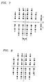
- FIG. 7 One illustrative, 32-symbol, constellation embodying these principles is shown in FIG. 7. This constellation is partitioned into four supersymbols, the constituent symbols thereof being labelled A, B, C and D, respectively.
- the distance labelled as “X” can be, for example, "1", thereby providing a constellation whose individual symbols are uniformly spaced. Or "X" can be greater than one--such as ⁇ 3--thereby increasing some of the inter-supersymbol distances. This provides an additional degree of design freedom in terms of achieving particular desired levels of error protection.
- the MID of the constellation of FIG. 7 is "2", which can be verified from a consideration of FIG. 8, in which the same constellation has been partitioned in order to provide equal error protection. That is, the minimum distance between any two symbols labelled "A", for example, is, in fact, "2". In FIG. 7, by contrast, the corresponding minimum distance, in accordance with the invention, is less than "2". Specifically, it is ⁇ 2. And note that, from a graphical perspective, subsets A and B overlap one another, as do subsets C and D. (It is thus not possible to draw a box around the supersymbols, as was done in FIG. 4.)
- FIG. 9 Another illustrative constellation--this one having 64 symbols--is shown in FIG. 9. Again, the constellation is partitioned into four supersymbols labelled using the same labelling convention as that used for FIG. 7.
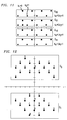
- FIGS. 10-14 show yet further constellations that can be used to advantage in conjunction with the present invention. The same labelling conventions are used and thus nothing further need be said about the configuration of these constellations.
- TABLE 1 is a table of codes in which 25% of the bits constitute the most important bits.
- TABLE 2 is a table of codes in which various other percentages of the bits constitute the most important bits.
- P denotes the average power per dimension
- PAR denotes the peak-to-average power ratio
- d 2 denotes the square Euclidian distance between the supersymbols represented by its arguments
- ⁇ denotes the nominal coding gain for the more important bits
- ⁇ denotes the nominal coding gain for the less important bits
- [ g 1, g 2] is the generator matrix, in octal notation, for the convolutional codes indicated
- L is the length of the parity check code.
- the degree of non-uniformity is determined by x.
- the tables also show the achievable gains as a function of x.
- the signal constellation typically, one might begin by choosing the signal constellation to allow for about one overall bit of redundancy per symbol.
- the number of supersymbols that is needed is determined by the actual number of important bits per symbol. For example, if more than 25%, and less than 50%, of the bits are important, and if the available bandwidth and required overall bit rate dictate, say, four information bits per symbol, then we will have to transmit one important bit per symbol. Assuming, further, that it is desired to provide some amount of redundancy for the important bits and that those bits will be used to select the supersymbols, then it may be reasonable to use a two-dimensional constellation having four supersymbols. Various of the constellations disclosed herein, or any other desired constellation, can be used as the initial design choice.
- multi-level codes in accordance with the present invention, can facilitate the attainment of the desired design criteria. If, upon analysis, it appears that the desired quality at the worst-case SNR is not achieved with the design arrived at to this point, other constellations and other codes can be explored with a view toward seeing whether it can, in fact, be achieved. If this does not appear possible, one or more of the previously given constraints, such as acceptable decoder complexity, may have to be relaxed. Other design criteria are conceivable as well as other parameters that may affect the choice of the code design.
- a pair of symbols from respective different supersymbols are assigned to the same less-important-bit values if the distance between that pair of symbols is the minimum distance between any pair of symbols of those two supersymbols.
- FIG. 10 Such a scheme is illustrated in FIG. 10, in which, like in FIG. 4, each symbol is labelled with a b 2, b 1, b 0 set of values. Note, for example, that the symbols labelled 110 in each of the supersymbols ⁇ 00, ⁇ 01, ⁇ 10 and ⁇ 11 all satisfy the aforementioned criterion.
Abstract
Description
- The present invention relates to the transmission of digital data including, particularly, the transmission of digital data which represents television (TV) signals.
- It is generally acknowledged that some form of digital transmission will be required for the next generation of television technology, conventionally referred to as high definition television, or HDTV. This requirement is due mostly to the fact that much more powerful video compression schemes can be implemented with digital signal processing than with analog signal processing. However, there has been some concern about getting committed to an all-digital transmission system because of the potential sensitivity of digital transmission to small variations in signal-to-noise ratio, or SNR, at the various receiving locations.
- This phenomenon--sometimes referred to as the "threshold effect"--can be illustrated by considering the case of two television receivers that are respectively located at 50 and 63 miles from a television broadcast station. Since the power of the broadcast signal varies roughly as the inverse square of the distance, it is easily verified that the difference in the amount of signal power received by the television receivers is about 2 dB. Assume, now, that a digital transmission scheme is used and that transmission to the receiver that is 50 miles distant exhibits a bit-error rate of 10⁻⁶. If the 2 dB of additional signal loss for the other TV set translates into a 2 dB decrease of the SNR at the input of the receiver, then this receiver will operate with a bit-error rate of about 10⁻⁴. With these kinds of bit-error rates, the TV set that is 50 miles away would have a very good reception, whereas reception for the other TV set would probably be very poor. This kind of quick degradation in performance over short distances is generally not considered acceptable by the broadcasting industry. (By comparison, the degradation in performance for presently used analog TV transmission schemes is much more graceful.)
- There is thus required a digital transmission scheme adaptable for use in television applications which overcomes this problem. Solutions used in other digital transmission environments--such as the use of a) regenerative repeaters in cable-based transmission systems or b) fall-back data rates or conditioned telephone lines in voiceband data applications--are clearly inapplicable to the free-space broadcast environment of television.
- An advantageous technique for overcoming the shortcomings of standard digital transmission for over-the-air broadcasting of digital TV signals-- referred to herein generically as "unequal-error-protection signaling"--comprises a particular type of source coding step followed by a particular type of channel mapping step. More specifically, the source coding step causes the television signal to be represented by two or more data streams while, in the channel mapping step, the mapping is such that the data elements of the various data streams have differing probabilities of channel-induced error, i.e., different probabilities of being erroneously detected at the receiver. Illustratively, a first one of the aforementioned data streams carries components of the overall television signal which are regarded as the most important--for example, the audio, the framing information, and the vital potions of the video information--and that data stream is mapped such that its data elements have the lowest probability of channel-induced error. A second one of the data streams carries components of the overall television signal which are regarded as less important than those of the first data stream and that data stream is mapped such that its data elements have a probability of channel-induced error that is not as low as those of the first data stream. In general, it is possible to represent the overall television signal with any number of data streams, each carrying components of varying importance and each having a respective probability of error. This approach allows a graceful degradation in reception quality at the TV set location because, as the bit error rate at the receiver begins to increase with increasing distance from the broadcast transmitter, it will be the bits that represent relatively less important portions of the TV signal information that will be the first to be affected.
- In a scheme which implements the above-described overall concept in which different levels of error protection are provided for different classes of data elements generated by the source enclosing step, but which provides enhanced noise immunity via the use of coded modulation, such as trellis-coded modulation, the symbols in a predetermined 2N-dimensional channel symbol constellation, N ≧ 1, are divided into groups, each of which is referred to as a "supersymbol." During each of a succession of symbol intervals, a predetermined number of the most important data elements are channel encoded, and the resulting channel coded data elements identify a particular one of the supersymbols. The remaining data elements, which may also be channel encoded, are used to select for transmission a particular symbol from the identified supersymbol.
- The approach as thus far described is similar in a general way to conventional coded modulation schemes in that the latter also divide the channel symbols into groups, typically referred to as "subsets." However, in conventional coded modulation schemes, the subsets are formed under the constraint that the minimum Euclidean distance (hereinafter referred to as the "minimum distance") between the symbols in a subset is greater than the minimum distance between the symbols in the constellation as a whole. In the described approach, however, the minimum distance between the symbols of a supersymbol is the same as the minimum distance between the symbols in the constellation as a whole. This distance property allows for greater amount of noise immunity for the most important data elements than for the other data elements, that immunity being optimized by keeping the minimum distance between supersymbols as large as possible--usually greater than the minimum distance between the symbols of the constellation. Specifically, once the supersymbols are defined, it is possible to design codes for the most important data elements based on the distances between the supersymbols, i.e., as though each supersymbol were a conventional symbol in a conventional constellation. This being so, a particular degree of noise immunity can be achieved for the most important data elements that is greater than what can be achieved for the other data elements.
- The present invention provides the designer of unequal-error-protection signaling schemes of the above-described type with additional flexibility. In accordance with the invention, so-called multi-level coding is used to code the data elements of at least one of the data streams that are input to the channel mapping step. For example, multi-level coding can be used to code the data elements which ultimately determine the supersymbol selection. Alternatively, it may be used to code the data elements which determine the selection of a particular symbol from within a selected supersymbol. Or multi-level coding can be used for both streams. The particular way in which the multi-level coding is used will depend on the requirements of any particular application in terms of the degree of error protection desired to be afforded to any particular class of the data being coded.
- There are at least two important advantages to this approach. One is that it provides an enhanced flexibility in designing a channel coding to realize a desired percentage of the overall data stream being coded that is to be regarded, and treated, as most important. Another advantage is that it provides an enchanced flexibility in apportioning the available redundancy between the most important data and the less important data, thereby providing a mechanism for achieving particular desired different levels of error protection for those two classes of data. A yet further advantage is that this approach allows differential levels of protection to be afforded to substreams of data elements within any of the streams that are multi-level coded in accordance with the invention.
- Multi-level coding per se is a technique already known in the prior art. In accordance with that technique, data elements to be coded are divided into two or more substreams. Each of one or more of the substreams is then individually redundancy coded using a code of any desired type. The individual encoded substreams--along with any substreams that were left uncoded--form the output of the multi-level code. That output is then used in the prior art to identify channel symbols of a predetermined constellation for transmission over a channel. However, the prior art does not encompass the teaching, lying at the heart of the present invention, that multi-level coding can be advantageously used to code one or more of the data streams of an overall unequal-error-protection signaling scheme.
- Advantageously, particular desired combinations of a) coding gain for the most important data elements, b) coding gain for the less important data elements, and c) percentage of most important data elements are more readily achievable by incorporating one or more multi-level codes in an unequal-error-protection signaling scheme in accordance with the invention, than when single-level codes are used. From the coding theory standpoint, this result can be understood as arising out of the fact that the invention allows the redundancy introduced into the overall coding scheme to be allocated in virtually any desired proportion between the coding of the most important data elements and coding of the less important data elements.
-
- FIG. 1 is a block diagram of a transmitter embodying the principles of the invention;
- FIG. 2 is a block diagram of a receiver for signals transmitted by the transmitter of FIG. 1;
- FIG. 3 depicts a prior art signal constellation;
- FIG. 4 depicts a signal constellation illustratively used by the transmitter of FIG. 1;
- FIGS. 5 and 6 show illustrative multi-level coders used in the transmitter of FIG. 1 in accordance with the invention;
- FIG. 7 depicts a signal constellation that can alternatively be used by the transmitter of FIG. 1;
- FIG. 8 depicts a signal constellation of the type typically used in equal error protection schemes;
- FIGS. 9-14 depict further signal constellations that can alternatively be used by the transmitter of FIG. 1; and
- FIGS. 15 and 16 show illustrative multi-stage decodes used in the receiver of FIG. 2 in accordance with the invention.
- Before proceeding with a description of the illustrative embodiments, it should be noted that various ones of the digital signaling concepts described herein are all well known in, for example, the digital radio and voiceband data transmission (modem) arts and thus need not be described in detail herein. These include such concepts as multidimensional signaling using 2N-dimensional channel symbol constellations, where N is some integer, trellis coding; scrambling; passband shaping; equalization; Viterbi, or maximum-likelihood, decoding; etc. These concepts are described in such U.S. patents as U.S. 3,810,021, issued May 7, 1974 to 1. Kalet et al.; U.S. 4,015,222, issued March 29, 1977 to J. Werner; U.S. 4,170,764, issued October 9, 1979 to J. Salz et al.; U.S. 4,247,940, issued January 27, 1981 to K. H. Mueller et al.; U.S. 4,304,962, issued December 8, 1981 to R. D. Fracassi et al.; U.S. 4,457,004, issued June 26, 1984 to A. Gersho et al.; U.S. 4,489,418, issued December 18, 1984 to J. E. Mazo; U.S. 4,520,490, issued May 28, 1985 to L. Wei; and U.S. 4,597,090, issued June 24, 1986 to G. D. Forney, Jr.
- It may also be noted before proceeding that various signal leads shown in the FIGS. may carry analog signals, serial bits or parallel bits, as will be clear from the context.
- Turning now to FIG. 1, television (TV)
signal source 101 generates an analog video signal representing picture information or "intelligence," which signal is passed on tosource encoder 104. The latter generates a digital signal comprised of data elements in which at least one subset of the data elements represents a portion of the information, or intelligence, that is more important than the portion of the information, or intelligence, represented by the rest of the data elements. Illustratively, each data element is a data bit, with an average m+k information bits being generated for each of a succession of symbol intervals. The symbol intervals are comprised of N signaling intervals, where 2N is the number of dimensions of the constellation (as described below). The signaling intervals have duration of T seconds and, accordingly, the symbol intervals each have a duration of NT seconds. The embodiments explicitly disclosed herein happen to use two-dimensional constellations, i.e., N = 1. For those embodiments, then, the signaling intervals and the symbol intervals are the same. - Of the aforementioned m+k information bits, the bits within the stream of m bits per symbol interval, appearing on
lead 105, are more important than the bits within the stream of k bits per symbol interval, appearing onlead 106. - The bits on
leads scramblers leads scramblers leads encoders leads constellation mapper 131, illustratively realized as a lookup table or as a straightforward combination of logic elements. Conventional pass-band shaping and television modulation are then performed bypassband shaper 141 andtelevision modulator 151, respectively. The resultant analog signal is then broadcast viaantenna 152 over a communication channel, in this case a free-space channel. - In order to understand the theoretical underpinnings of the invention, it will be useful at this point to digress to a consideration of FIG. 3. The latter depicts a standard two-dimensional data transmission constellation of the type conventionally used in digital radio and voiceband data transmission systems. In this standard scheme--conventionally referred to as quadrature-amplitude modulation (QAM)--data words each comprised of four information bits are each mapped into one of 16 possible two-dimensional channel symbols. Each channel symbol has an in-phase, or I, coordinate on the horizontal axis and has a quadrature-phase, or Q, coordinate on the vertical axis. On each axis, the channel symbol coordinates are ± 1 or ± 3 so that the distance between each symbol and each of the symbols that are horizontally or vertically adjacent to it is the same for all symbols --that distance being "2". As a result of this uniform spacing, essentially the same amount of noise immunity is provided for all four information bits.
- As is well known, it is possible to provide improved noise immunity without sacrificing bandwidth efficiency (information bits per signaling interval) using a coded modulation approach in which an "expanded" two-dimensional constellation having more than (in this example) 16 symbols is used in conjunction with a trellis or other channel code. For example, one can use a 32-symbol, two-dimensional constellation together with an 8-state trellis code to achieve approximately 4 dB of enhanced noise immunity over the uncoded case of FIG. 3, while still providing for the transmission of four information bits per signaling interval. Here, too, however, essentially the same amount of noise immunity is provided for all four information bits.
- Moreover, it is known that the known noise immunity and bandwidth efficiency advantages of coded modulation are achieved while providing different levels of protection against channel-induced error for different classes of bits. Specifically, it is possible to achieve a level of error protection for a class of most important bits which is substantially greater than what can be achieved with the aforementioned conventional coded modulation approach. Indeed, the transmitter of FIG. 1 embodies that concept, as will now be described in further detail.
- The constellation used in the transmitter of FIG. 1 is illustratively the two-dimensional 32-symbol constellation shown in FIG. 4. The symbols in the signal constellation are divided into groups referred to as "supersymbols." Specifically, the constellation of FIG. 4 is divided into 2 r = 2² = 4 supersymbols. In this example, the points in the four quadrants constitute respective supersymbols, as denoted by a box enclosing each group. The supersymbols are denoted generically as Ω b
4 b3 where b₄ = 0,1 and b₃ = 0,1. The four supersymbols are thus Ω₀₀, Ω₀₁, Ω₁₀, and Ω₁₁. - In this example, m = 1.625 and k = 2.125 so that the overall bit rate is 3.75 bits per symbol with 43.33% of the bits being in the class of most important bits. (The manner in which such fractional average bit rates can be achieved in practice will become clear as this description continues.)
Encoder 114 adds an average 0.375 redundant bits for every 1.625 bits that are input to encoder 114 so that r = 2.Encoder 115 adds an average 0.875 redundant bits for every 2.125 bits that are input to encoder 115 so that p = 3. The r = 2 bits onlead 121 identify one of the four supersymbols and the p = 3 symbols onlead 122 select a particular one of the eight channel symbols within the identified supersymbol. The partitioning of the constellation is such that the minimum distance between the symbols of a supersymbol--that distance being denoted as d₂ in FIG. 4--is the same as the minimum distance between the symbols in the constellation as a whole. Given this characteristic, increased noise immunity for the most important bits can be provided via appropriate selection of a) the codes implemented byencoders - Specifically, a coded modulation scheme can now be constructed for the most important bits as though the four supersymbols were four conventional symbols in a conventional constellation. To design such a coded modulation scheme, the four supersymbols are partitioned, as is conventional, into a predetermined number of subsets. In this case, there are two subsets, where the value of b₃ denotes which subset each of the supersymbols belongs to. Thus, one subset, referred to as subset "0", comprises supersymbols Ω₀₀ and Ω₁₀ and the other, referred to as subset "1", comprises supersymbols Ω₀₁ and Ω₁₁. An appropriate code is used to encode the most important input bits to generate a stream of coded output bits which a) define a sequence of these subsets and b) for each subset of the sequence, select a particular supersymbol within that subset. The less important bits are then used to select for transmission a particular symbol from each of the thus-selected supersymbols. In this example, as already seen, this latter selection also involves the use of coded modulation.
- In accordance with the present invention, at least one of the channel encoders implements a multi-level code. In this example, in particular, both of them do. As noted earlier, a multi-level code is one in which the data elements--in this embodiment, bits--to be coded are divided into two or more substreams. Each of one or more of the substreams is then individually redundancy coded using a code of any desired type. The individual encoded substreams--along with any substreams that were left uncoded--form the output of the multi-level code.
- Particular illustrative embodiments for
encoders Encoder 114 implements a two-level code and, as such, includes two coders--coders coder 1141 is a conventional rate R = 7/8 zero-sum parity check code such as shown in G. C. Clark, Jr. and J. B. Cain, Error-Correction Coding for Digital Communications New York: Plenum, 1981). The redundancy code implemented bycoder 1142 is a conventional rate R = 3/4 punctured convolutional code such as shown in Y. Yasuda et al, "High-rate punctured convolutional codes for soft decision Viterbi decoding," IEEE Trans. Comm., Vol. COM-32, 1984, pp. 315-318. In operation, a serial-to-parallel (S/P)converter 1144 withinencoder 114 takes in 13 bits over 8 symbol intervals, yielding an average input bit rate of m =1.625 bits per symbol interval as noted earlier. The output ofconverter 1144 comprises two substreams of bits. In one substream, the bits are provided in parallel groups of seven tocoder 1141. In the other substream, the bits are provided in parallel groups of six tocoder 1142. For every group of seven input bits,coder 1141 generates eight output bits which are applied to 8-bit buffer 1147. At the same time, for every group of six input bits,coder 1142 generates eight output bits which are applied to 8-bit buffer 1148. The contents ofbuffers lead 121 for each symbol interval. These bits are the aforementioned bits b₃ and b₄. As such, the former identifies one of the two subsets "0" and "1" and the other identifies one of the two supersymbols from the identified subset, the two bits b₃ and b₄ thus identifying one of the four supersymbols Ω₀₀, Ω₀₁, Ω₁₀ and Ω₁₁. -
Encoder 115 implements a three-level code and, as such, includescoders Coders coders converter 1154 takes in 17 bits over 8 symbol intervals, yielding an average input bit rate of k = 2.125 bits per symbol interval, as noted earlier. The output ofconverter 1154 comprises three substreams of bits. In one substream, the bits are provided in parallel groups of seven tocoder 1151. In the second stream, the bits are provided in parallel groups of six tocoder 1152. In the third group, the bits are provided in parallel groups of four tocoder 1153. For every group of seven input bits,coder 1151 generates eight output bits which are applied to 8-bit buffer 1157. For every group of six input bits,coder 1152 generates eight output bits which are applied to 8-bit buffer 1158. For every group of four input bits,coder 1153 generates eight output bits which are applied to 8-bit buffer 1159. - The contents of
buffers lead 122 for each symbol interval. These three bits--denoted b₂, b₁ and b₀-- select a particular symbol from the supersymbol identified at the output ofencoder 114. To this end, each of the symbols in the constellation is labelled with a three-bit label as shown in FIG. 4. These three bits are, in fact, the aforementioned bits b₂, b₁ and b₀. - The symbols of each supersymbol are partitioned at a first level of partitioning into two subsets. Each subset is comprised of four symbols as denoted by the labelled b₀ value. Thus one subset is comprised of the four symbols denoted 000, 010, 100 and 110 and the other subset is comprised of the four symbols denoted 001, 011, 101 and 111. The symbols of each of these subsets are partitioned at a second level of partitioning into two second-level subsets, which are identified by their labelled b₀ and b₁ values. Each second-level subset is comprised of two symbols identified by b₂.
- The assignment of three-bit labels to the symbols of each supersymbol is not arbitrary. Rather, the codes implemented by
coders coder 1153--is used at the first level of partitioning to generate b₀ because the minimum distance between the subsets at the first level is the smallest, that distance being d₁. The second- and least-powerful codes, the rate R = 3/4 and rate R = 7/8 codes implemented bycoders - The advantages provided by such use of multi-level codes in an unequal error protection signaling scheme are discussed hereinbelow. First, however, reference is made to the receiver of FIG. 2.
- In particular, the analog broadcast signal is received by
antenna 201; subjected to conventional television front-end processing inprocessing unit 211 including, for example, demodulation; and converted to digital form by A/D converter 212. The signal is then equalized bypassband channel equalizer 221, which generates a signal representing the equalizer's best estimate as to the I and Q component values of the transmitted symbol. This estimate, which is referred to hereinbelow as the "received symbol signal," is passed onparallel rails channel decoders channel decoder 231 is to identify the most likely sequence of supersymbols, while the function ofchannel decoder 232 is to identify the most likely sequence of symbols, given that sequence of supersymbols. The output ofdecoder 232 onlead 234 thus comprises the bits b₃ and b₄, while the output ofdecoder 231 onlead 233 thus comprises the bits b₀, b₁ and b₂. - Since the streams of most-important and less-important bits are, in this embodiment, both multi-level coded, the
channel decoders - In particular,
channel decoder 232 first recovers the bits encoded bycoder 1142 within encoder 114 (FIG. 5), independent of, and without reference to, any decoding performed on the bits encoded bycoder 1141. To this end, as shown in FIG. 15,decoder 232 includesdecode b₃ circuitry 2321, decode b₄ circuitry 2323 anddelay element 2322. In operation, the received symbol signal is processed bycircuitry 2321 to decode bit b₃ by first finding the symbol closest to the received signal symbol--and the associated metrics--in (Ω₀₁ ν Ω₁₁) and in (Ω₀₀ ν Ω₁₀). The trellis path is then extended as per conventional Viterbi decoding of the code implemented by coder 1142 (FIG. 5) to generate a final decision about a previously encoded information bit that was encoded by that coder. The decoded bit--one of the original most important bits--is provided as an output onlead 234. It is also re-encoded withincircuitry 2321 using the code ofcoder 1142 to provide bit b₃ to circuitry 2323 as well as to channel decoder 231 (FIG. 16), as described below, vialead 236. A version of the received symbol signal is delayed bydelay element 2322 by a time sufficient to provide the value of bit b₃ as just described. That signal is then provided to circuitry 2323 along with bit b₃ to circuitry 2323 which then proceeds to decode bit b₄. This is carried out, in particular, by first finding the symbol closest to the received signal symbol--and the associated metrics--in supersymbol Ω 0b3 and in supersymbol Ω 1b3 . The metrics are stored in a buffer and are used to perform maximum likelihood decoding of the code implemented by clear 1141 (FIG. 5), thereby to provide another of the most important bits onlead 234. At the same time, that bit is re-encoded within circuitry 2323 to provide bit b₄ to channeldecoder 231 onlead 236. - It may be noted at this point that, obviously,
circuitries 2321 and 2323 must be provided within information about the constellation that is being used in order to carry out their respective functions. That information is illustratively stored in aconstellation store 2325 whose output--denoted as "A"--is provided to both of those circuitries, as well as to decoder 231 of FIG. 16. - With the most important bits now provided on
leads 234 and the values of bits b₃ and b₄ now being provided todecoder 231 onlead 236, the multi-stage decoding can now proceed--within the latter channel decoder--to recover the less important bits. To this end, as shown in FIG. 16,decoder 231 includesdecode b₀ circuitry 2315, decodeb ₁ circuitry 2316, decodeb ₂ circuitry 2317, and delayelements decoder 232 so thatcircuitry 2315 can be provided with bits b₃ and b₄ at the same time that it receives the received symbol signal.Circuitry 2315 then proceeds by first finding, within the supersymbol Ω b4 b3 , those symbols having b₀ = 0 and b₁ = 1 which are respectively closest to the received signal symbol. The trellis path is then extended, as before, using the metrics associated with those two closest symbols, leading ultimately to a decoding of bit b₀ and hence a recovery of one of the less important bits. That bit is then re-encoded withincircuitry 2315 so as to be able to provide the value of bit b₀ tocircuitries delay elements circuitries - Decoding in the case where multi-dimensional symbols are used is carried out in a similar manner, as will be appreciated by those skilled in the art.
- The bits output by
decoder leads descramblers scramblers source decoder 253, thereby recovering the original television information, or intelligence. That signal is then presented to the television viewer ontelevision set 260. - The performance of the overall unequal error protection signaling scheme implemented by the system of FIGS. 1 and 2, as just described, can now be characterized in terms of the nominal coding gain (i.e., the coding gain at very low error rates), this being the gain in signal-to-noise ratio over that of an uncoded 16-QAM system. The gain for the most important bits is 6.24 dB and for the less important bits is 2.70 dB when the number of states of each of the convolutional codes is chosen to be 16. The unique advantage of the present invention, however, does not wholly lie with the particular levels of coding gain achieved. Coding arrangements known in the prior art may achieve comparable, or even better, coding gain results in particular applications. However, where the invention is particularly advantageous is in its ability to provide the system designer with a greatly enhanced capability to pick the desired performance criteria, given the application, and to then readily arrive at a coding scheme which meets those criteria.
- For example, the overall data rate of the above-described system can be increased from 3.75 to 3.875 bits per symbol without affecting the coding gain by changing the code implemented by
coders coders coder 1151 so that the bits applied to buffer 1157 are uncoded bits. This arrangement achieves coding gains of 8 dB for the most important bits and 0.22 dB for the less important bits. Additionally, by changing the ratio of d₂/d₁ in FIG. 4, one can trade off the gains of the most important and less important bits. It will thus be seen that the invention allows for the use of a virtually unlimited range of design parameters-- including the code rates, code complexity, overall coding redundancy, fraction of that redundancy used for error protection of the most important bits (as opposed to that used for the less important bits)--in order to meet desired system design criteria. This flexibility can be further enhanced by using various different signal constellations, including constellations having various different numbers of symbols, symbol spacings, supersymbol groupings and subset partitionings. Indeed a new class of constellations may be advantageously used to provide the system designer with even further flexibility. These constellations are characterized by particular distance relationships within the constellation. Indeed, an important parameter in the design of coded modulation schemes is the so-called intra-subset distance. This parameter is the minimum distance between any two symbols in the subset. In coded modulation schemes which, unlike in the present invention, seek to provide equal error protection, the design constraint is to partition the constellation into subsets in such a way as to maximize the minimum of the intra-subset distances taken across all the subsets. This value, which we define as the "maximum intra-subset distance," or MID, has been achieved when, given a particular partitioning, any further attempt to increase the intra-subset distance of any particular subset (by making any other symbol-to-subset assignment changes) would not result in a further increase in the aforesaid minimum value. - Further, an important distinction between equal error protection and unequal error protection schemes needs to be kept in mind In the former, the error protection for the so-called coded bits is determined by the minimum distance between subset sequences while the error protection for the uncoded bits is determined by the minimum distance between the symbols within a subset. Designers of equal-error-protection schemes want these two minimums to be as close to each other as possible because they want equal error protection for all the data. The performance of these schemes is dominated by the distance between the symbols within a subset. This results from the fact that one can always increase the complexity of the code in order to achieve whatever distance is desired between subset sequences.
- In the case of unequal error protection, by contrast, the symbols in a supersymbol are selected by the less important bits. Thus the distance between these symbols can be significantly less than the MID. Indeed it is limited only by the distance between the symbols of the constellation as a whole. This distance is chosen to provide the necessary level of error protection for the less important bits. Once we fix that distance, then the subset partitioning can be done to take advantage of this fact, thus making possible the realization of greater distances between the supersymbol sequences than would be possible with conventional coded modulation for the same complexity. We are, thus, no longer constrained to keep the symbols within a supersymbol far away from each other.
- Taking the foregoing into account, constellations useful in unequal-error-protection signaling schemes are characterized by the fact that the minimum distance between at least some of the symbols of at least one of the supersymbols is less than the MID. Indeed, constellations of this general type are known. However, in the prior art, the minimum distance between the symbols of the supersymbols is the same as the minimum distance between the symbols of the constellation as a whole. By contrast, the constellations in question are not so constrained. That is, the minimum distance between at least ones of the symbols of at least one of the supersymbols is greater than the minimum distance between the symbols of the constellation as a whole while, again, still being less than the MID. Graphically speaking, constellations meeting this criterion will generally appear to have supersymbols which, at least to some degree, overlap (as do the subsets of the constellations used for equal error protection schemes). That is, at least one symbol of a least one supersymbol will be closer to each of a pair of symbols of a different supersymbol than that pair of symbols are to each other.
- One illustrative, 32-symbol, constellation embodying these principles is shown in FIG. 7. This constellation is partitioned into four supersymbols, the constituent symbols thereof being labelled A, B, C and D, respectively. The distance labelled as "X" can be, for example, "1", thereby providing a constellation whose individual symbols are uniformly spaced. Or "X" can be greater than one--such as √3--thereby increasing some of the inter-supersymbol distances. This provides an additional degree of design freedom in terms of achieving particular desired levels of error protection.
- The MID of the constellation of FIG. 7 is "2", which can be verified from a consideration of FIG. 8, in which the same constellation has been partitioned in order to provide equal error protection. That is, the minimum distance between any two symbols labelled "A", for example, is, in fact, "2". In FIG. 7, by contrast, the corresponding minimum distance, in accordance with the invention, is less than "2". Specifically, it is √2. And note that, from a graphical perspective, subsets A and B overlap one another, as do subsets C and D. (It is thus not possible to draw a box around the supersymbols, as was done in FIG. 4.)
- Another illustrative constellation--this one having 64 symbols--is shown in FIG. 9. Again, the constellation is partitioned into four supersymbols labelled using the same labelling convention as that used for FIG. 7.
- FIGS. 10-14 show yet further constellations that can be used to advantage in conjunction with the present invention. The same labelling conventions are used and thus nothing further need be said about the configuration of these constellations.
- The following two tables illustrate the tremendous flexibility provided by the present invention in terms of providing unequal-error-protection signaling schemes which provide various different combinations of a) percentage of most important bits, b) degree of overall code redundancy, c) coding gains, and d) ratio of peak-to-average power (which is an important consideration in power-limited channels such as terrestrial and satellite telephone channels). TABLE 1 is a table of codes in which 25% of the bits constitute the most important bits. TABLE 2 is a table of codes in which various other percentages of the bits constitute the most important bits.


- In these tables, P denotes the average power per dimension; PAR denotes the peak-to-average power ratio; d² denotes the square Euclidian distance between the supersymbols represented by its arguments; Γ denotes the nominal coding gain for the more important bits; γ denotes the nominal coding gain for the less important bits; and [g 1, g₂] is the generator matrix, in octal notation, for the convolutional codes indicated; L is the length of the parity check code. For non-uniform constellations, the degree of non-uniformity is determined by x. The tables also show the achievable gains as a function of x.
- In designing unequal error protection signaling schemes, such as those just presented in TABLES 1 and 2, one typically must first be given the values of certain parameters. These include (a) available channel bandwidth, (b) the worst-case channel SNR, (c) the number of classes of bits, (d) the percentage of bits in each class, (e) the desired quality of the final received signal under the worst-case channel conditions, (f) acceptable decoder complexity, and (g) peak-to-average power ratio. One can then proceed to design an unequal-error-protection scheme consistent with the given parameter values.
- Typically, one might begin by choosing the signal constellation to allow for about one overall bit of redundancy per symbol. The number of supersymbols that is needed is determined by the actual number of important bits per symbol. For example, if more than 25%, and less than 50%, of the bits are important, and if the available bandwidth and required overall bit rate dictate, say, four information bits per symbol, then we will have to transmit one important bit per symbol. Assuming, further, that it is desired to provide some amount of redundancy for the important bits and that those bits will be used to select the supersymbols, then it may be reasonable to use a two-dimensional constellation having four supersymbols. Various of the constellations disclosed herein, or any other desired constellation, can be used as the initial design choice. One would then proceed to select codings to be used for the bit streams depending on the relative redundancies desired to be allocated to them Importantly, the use of multi-level codes, in accordance with the present invention, can facilitate the attainment of the desired design criteria. If, upon analysis, it appears that the desired quality at the worst-case SNR is not achieved with the design arrived at to this point, other constellations and other codes can be explored with a view toward seeing whether it can, in fact, be achieved. If this does not appear possible, one or more of the previously given constraints, such as acceptable decoder complexity, may have to be relaxed. Other design criteria are conceivable as well as other parameters that may affect the choice of the code design.
- In accordance with an advantageous technique for assigning the values of the bits that are used to select the symbols from each identified supersymbol to those symbols, a pair of symbols from respective different supersymbols are assigned to the same less-important-bit values if the distance between that pair of symbols is the minimum distance between any pair of symbols of those two supersymbols. Such a scheme is illustrated in FIG. 10, in which, like in FIG. 4, each symbol is labelled with a b₂, b₁, b₀ set of values. Note, for example, that the symbols labelled 110 in each of the supersymbols Ω₀₀, Ω₀₁, Ω₁₀ and Ω₁₁ all satisfy the aforementioned criterion. Such a labelling scheme--which is achievable to varying degrees, depending on the constellation and supersymbol geometries--is advantageous in that it improves the probability that the less-important-bit values will be decoded properly, even if an error is made in recovering the correct supersymbol sequence. Beyond this, it may be possible to achieve former benefit by similar judicious choice of bit assignments for those symbols which do not meet the above-mentioned minimum distance criterion. This would need to be done, however, within the constraints that are imposed by any coding that is implemented for the symbols within the supersymbol, as was, in fact, the case of the example described above in conjunction with the constellation of FIG. 4.
- The foregoing merely illustrates the principles of the present invention. For example, although the illustrative embodiments are implemented using two data streams--the most- and less-important--the invention can be used in schemes which include three or more streams. Additionally, although two-dimensional constellations are shown, the invention can be used in schemes using constellations with more than two dimensions.
- It may also be noted that although the invention is illustrated herein as being implemented with discrete functional building blocks, e.g., source coders, scramblers, etc., the functions of any one or more of those building blocks can be carried out using one or more appropriate programmed processors, digital signal processing (DSP) chips, etc.
Claims (5)
- Apparatus for communicating information comprising
means (104) for generating a digital signal representing the information, the digital signal being comprised of at least first and second streams of data elements,
CHARACTERIZED BY
means (110, 111, 114, 115, 131) for channel mapping the digital signal in such a way that the probability of channel-induced error for the data elements of the first data stream is less than the probability of channel-induced error for the data elements of the second data stream, said channel mapping means including means (114) for multi-level coding at least one of said streams, and
means (141, 151) for transmitting the channel mapped signal over a communication channel. - The invention of claim 1 wherein said information is television signal information and wherein first stream of data represents television signal information that is more important than the television signal information represented by the data elements of said second stream.
- The invention of claim 1 wherein said at least one of said streams includes at least two substreams, and wherein said multi-level coding means includes means (1141, 1142) for redundancy coding at least one of said substreams and for combining all of the redundancy coded substreams of said one stream and any of its substreams that are not redundancy coded to form a coded signal for use in the channel mapping.
- The invention of claim 3 wherein the channel mapping means selects a sequence of symbols from a predefined constellation to represent the data elements, the constellation being comprised of supersymbols, the minimum distance between the symbols within at least one of the supersymbols being less than the maximum intra-subset distance for said constellation.
- The invention of claim 4 wherein the minimum distance between the symbols of said at least one of the supersymbols is greater than the minimum distance between symbols of the constellation as a whole.
Applications Claiming Priority (2)
| Application Number | Priority Date | Filing Date | Title |
|---|---|---|---|
| US07/785,723 US5544328A (en) | 1991-10-31 | 1991-10-31 | Coded modulation with unequal error protection |
| US785723 | 1991-10-31 |
Publications (3)
| Publication Number | Publication Date |
|---|---|
| EP0540231A2 true EP0540231A2 (en) | 1993-05-05 |
| EP0540231A3 EP0540231A3 (en) | 1993-08-11 |
| EP0540231B1 EP0540231B1 (en) | 1998-01-21 |
Family
ID=25136434
Family Applications (1)
| Application Number | Title | Priority Date | Filing Date |
|---|---|---|---|
| EP92309608A Expired - Lifetime EP0540231B1 (en) | 1991-10-31 | 1992-10-21 | Coded modulation with unequal error protection |
Country Status (5)
| Country | Link |
|---|---|
| US (1) | US5544328A (en) |
| EP (1) | EP0540231B1 (en) |
| JP (1) | JP2801482B2 (en) |
| DE (1) | DE69224142T2 (en) |
| SG (1) | SG59926A1 (en) |
Cited By (16)
| Publication number | Priority date | Publication date | Assignee | Title |
|---|---|---|---|---|
| EP0540232A2 (en) * | 1991-10-31 | 1993-05-05 | AT&T Corp. | Coded modulation with unequal error protection |
| EP0589709A2 (en) * | 1992-09-25 | 1994-03-30 | Matsushita Electric Industrial Co., Ltd. | Multiresolution transmission system |
| EP0624019A2 (en) * | 1993-05-05 | 1994-11-09 | General Instrument Corporation Of Delaware | Trellis coded QAM using punctured convolutional codes |
| US5802241A (en) * | 1992-03-26 | 1998-09-01 | Matsushita Electric Industrial Co., Ltd. | Communication system |
| EP0880838A1 (en) * | 1996-11-14 | 1998-12-02 | Motorola, Inc. | Method of communicating according to a trellis code chosen from a fixed set of baseband signal points |
| GB2329803A (en) * | 1997-04-10 | 1999-03-31 | Nokia Mobile Phones Ltd | Decreasing the frame error rate in data transmission |
| US5892879A (en) * | 1992-03-26 | 1999-04-06 | Matsushita Electric Industrial Co., Ltd. | Communication system for plural data streams |
| EP0919087A1 (en) * | 1997-01-17 | 1999-06-02 | Motorola, Inc. | System and device for, and method of, communicating according to a composite code |
| US6256357B1 (en) | 1992-03-26 | 2001-07-03 | Matsushita Electric Industrial Co., Ltd. | Communication system |
| FR2817092A1 (en) * | 2000-11-21 | 2002-05-24 | Thomson Csf | Transmission condition transmission chain of optimization having communications network input receiving signal quality parameter set evaluating quality and optimizing transmitter chain element. |
| USRE38483E1 (en) | 1992-03-26 | 2004-03-30 | Matsushita Electric Industrial Co., Ltd. | Communication system |
| US6724976B2 (en) | 1992-03-26 | 2004-04-20 | Matsushita Electric Industrial Co., Ltd. | Communication system |
| US6728467B2 (en) | 1992-03-26 | 2004-04-27 | Matsushita Electric Industrial Co., Ltd. | Communication system |
| EP2134052A1 (en) * | 2008-06-13 | 2009-12-16 | THOMSON Licensing | An improved QAM transmission scheme for AWGN channels |
| US7894541B2 (en) | 1992-03-26 | 2011-02-22 | Panasonic Corporation | Communication system |
| USRE42643E1 (en) | 1991-03-27 | 2011-08-23 | Panasonic Corporation | Communication system |
Families Citing this family (26)
| Publication number | Priority date | Publication date | Assignee | Title |
|---|---|---|---|---|
| US5844922A (en) * | 1993-02-22 | 1998-12-01 | Qualcomm Incorporated | High rate trellis coding and decoding method and apparatus |
| US5745528A (en) * | 1995-07-13 | 1998-04-28 | Zenith Electronics Corporation | VSB mode selection system |
| JP3634082B2 (en) * | 1996-08-29 | 2005-03-30 | 富士通株式会社 | Transmitter and receiver |
| US5822371A (en) * | 1997-02-14 | 1998-10-13 | General Datacomm Inc. | Mapper for high data rate signalling |
| EP0935363A4 (en) | 1997-06-19 | 2005-09-07 | Toshiba Kk | Information data multiplexing transmission system, multiplexer and demultiplexer used therefor, and error correcting encoder and decoder |
| US6405338B1 (en) * | 1998-02-11 | 2002-06-11 | Lucent Technologies Inc. | Unequal error protection for perceptual audio coders |
| US7215718B1 (en) * | 1999-04-28 | 2007-05-08 | At&T Corp. | Combined channel coding and space-time block coding in a multi-antenna arrangement |
| CN1342354A (en) | 1998-09-04 | 2002-03-27 | 美国电报电话公司 | Combined channel coding and space-block coding in multi-antenna arrangement |
| US6754290B1 (en) | 1999-03-31 | 2004-06-22 | Qualcomm Incorporated | Highly parallel map decoder |
| US6397368B1 (en) * | 1999-12-06 | 2002-05-28 | Intellon Corporation | Forward error correction with channel adaptation |
| WO2001065748A1 (en) * | 2000-02-29 | 2001-09-07 | Fujitsu Limited | Encoding method for multicarrier transmission and encoder using the same |
| US6889351B1 (en) * | 2000-03-30 | 2005-05-03 | Koninklijke Philips Electronics, N.V. | Backward compatible multiple data stream transmission method and system for compressed domain signals |
| US7168031B2 (en) * | 2000-04-14 | 2007-01-23 | Siemens Aktiengesellschaft | Method for channel decoding a data stream containing useful data and redundant data, device for channel decoding, computer-readable storage medium and computer program element |
| WO2002007327A1 (en) * | 2000-07-17 | 2002-01-24 | Koninklijke Philips Electronics N.V. | Coding of data stream |
| US6898758B2 (en) * | 2001-06-20 | 2005-05-24 | Koninklijke Philips Electronics N.V. | Cross media error protection method and system |
| KR100800885B1 (en) * | 2001-08-13 | 2008-02-04 | 삼성전자주식회사 | Demodulation apparatus and method for communication using multi level modulation |
| US6727772B2 (en) * | 2002-05-01 | 2004-04-27 | Intel Corporation | Method and system for synchronizing a quadrature amplitude modulation demodulator |
| US8204079B2 (en) * | 2002-10-28 | 2012-06-19 | Qualcomm Incorporated | Joint transmission of multiple multimedia streams |
| US20040083417A1 (en) * | 2002-10-29 | 2004-04-29 | Lane Richard D. | Multimedia transmission using variable error coding rate based on data importance |
| US20040083495A1 (en) * | 2002-10-29 | 2004-04-29 | Lane Richard D. | Mulitmedia transmission using variable gain amplification based on data importance |
| US7613985B2 (en) * | 2003-10-24 | 2009-11-03 | Ikanos Communications, Inc. | Hierarchical trellis coded modulation |
| KR100589680B1 (en) * | 2004-07-26 | 2006-06-19 | 한국전자통신연구원 | Sending method and sending apparatus, receiving method and receiving apparatus for signal of mobile telecommunication system |
| US7987415B2 (en) * | 2006-02-15 | 2011-07-26 | Samsung Electronics Co., Ltd. | Method and system for application of unequal error protection to uncompressed video for transmission over wireless channels |
| WO2007100184A1 (en) * | 2006-02-28 | 2007-09-07 | Lg Electronics Inc. | Digital broadcasting system and method of processing data |
| JP5771134B2 (en) * | 2011-12-13 | 2015-08-26 | 日本放送協会 | Transmitting apparatus and receiving apparatus |
| US9380351B2 (en) * | 2014-01-17 | 2016-06-28 | Lg Display Co., Ltd. | Apparatus for transmitting encoded video stream and method for transmitting the same |
Citations (4)
| Publication number | Priority date | Publication date | Assignee | Title |
|---|---|---|---|---|
| EP0282298A2 (en) * | 1987-03-13 | 1988-09-14 | Space Systems / Loral, Inc. | Method and apparatus for combining encoding and modulation |
| EP0485105A2 (en) * | 1990-11-07 | 1992-05-13 | AT&T Corp. | Coding for digital transmission |
| EP0485108A2 (en) * | 1990-11-07 | 1992-05-13 | AT&T Corp. | Coded modulation with unequal levels of error protection |
| EP0540232A2 (en) * | 1991-10-31 | 1993-05-05 | AT&T Corp. | Coded modulation with unequal error protection |
Family Cites Families (6)
| Publication number | Priority date | Publication date | Assignee | Title |
|---|---|---|---|---|
| US4520490A (en) * | 1983-08-05 | 1985-05-28 | At&T Information Systems Inc. | Differentially nonlinear convolutional channel coding with expanded set of signalling alphabets |
| US4651320A (en) * | 1984-12-24 | 1987-03-17 | American Telephone And Telegraph Company | Inband coding of secondary data |
| JPS6339239A (en) * | 1986-08-05 | 1988-02-19 | Fujitsu Ltd | Encoing, modulating and demodulating circuit |
| US5134464A (en) * | 1990-11-16 | 1992-07-28 | North American Philips Corporation | Method and apparatus for the transmission and reception of a multicarrier digital television signal |
| US5029185A (en) * | 1989-07-28 | 1991-07-02 | At&T Bell Laboratories | Coded modulation for mobile radio |
| US5105443A (en) * | 1990-05-29 | 1992-04-14 | At&T Bell Laboratories | Inband coding of secondary data |
-
1991
- 1991-10-31 US US07/785,723 patent/US5544328A/en not_active Expired - Lifetime
-
1992
- 1992-10-21 EP EP92309608A patent/EP0540231B1/en not_active Expired - Lifetime
- 1992-10-21 SG SG1996000896A patent/SG59926A1/en unknown
- 1992-10-21 DE DE69224142T patent/DE69224142T2/en not_active Expired - Lifetime
- 1992-10-30 JP JP4314327A patent/JP2801482B2/en not_active Expired - Lifetime
Patent Citations (4)
| Publication number | Priority date | Publication date | Assignee | Title |
|---|---|---|---|---|
| EP0282298A2 (en) * | 1987-03-13 | 1988-09-14 | Space Systems / Loral, Inc. | Method and apparatus for combining encoding and modulation |
| EP0485105A2 (en) * | 1990-11-07 | 1992-05-13 | AT&T Corp. | Coding for digital transmission |
| EP0485108A2 (en) * | 1990-11-07 | 1992-05-13 | AT&T Corp. | Coded modulation with unequal levels of error protection |
| EP0540232A2 (en) * | 1991-10-31 | 1993-05-05 | AT&T Corp. | Coded modulation with unequal error protection |
Non-Patent Citations (8)
| Title |
|---|
| 1991, Turin, IT, SIGNAL PROCESSING of HDTV, III, pages 61 69, Elsevier, Amsterdam, NL; K. M. UZ et al.: 'Multiresolution Source and Channel Coding for Digital Broadcast of HDTV.' * |
| Correcting Codes.' * |
| IEEE TRANSACTIONS ON COMMUNICATIONS vol. 37, no. 3, March 1989, NEW YORK US pages 222 - 229 A. R. CALDERBANK: 'Multilevel Codes and Multistage Decoding.' * |
| IEEE TRANSACTIONS ON INFORMATION THEORY vol. 23, no. 3, 1977, NEW YORK US pages 371 - 377 H. IMAI / S. HIRAKAWA: 'A New Multilevel Coding Method Using Error-Correcting Codes.' * |
| MULTIDIMENSIONAL SYSTEMS AND SIGNAL PROCESSING, vol. 3, no. 2-3, May 1992, NL, pages 161-187; M. VETTERLI / K. M. UZ: 'Multiresolution Coding Techniques for Digital Television: A Review.' * |
| Proceedings of the Fourth International Workshop on HDTV and Beyond, 04.-06.09.1991, Turin, IT, SIGNAL PROCESSING of HDTV, III, pages 61 69, Elsevier, Amsterdam, NL; K. M. UZ et al.: 'Multiresolution Source and Channel Coding for Digital Broadcast of HDTV.' * |
| SIGNAL PROCESSING. IMAGE COMMUNICATION vol. 4, August 1992, AMSTERDAM NL pages 283 - 292 K. M. UZ ET AL.: 'Combined multiresolution source coding and modulation for digital broadcast of HDTV.' * |
| SMPTE JOURNAL vol. 101, no. 8, August 1992, SCARSDALE, NY US pages 538 - 549 W. F. SCHREIBER: 'Spread-Spectrum Television Broadcasting.' * |
Cited By (36)
| Publication number | Priority date | Publication date | Assignee | Title |
|---|---|---|---|---|
| USRE42643E1 (en) | 1991-03-27 | 2011-08-23 | Panasonic Corporation | Communication system |
| EP0540232A2 (en) * | 1991-10-31 | 1993-05-05 | AT&T Corp. | Coded modulation with unequal error protection |
| EP0540232A3 (en) * | 1991-10-31 | 1993-08-11 | American Telephone And Telegraph Company | Coded modulation with unequal error protection |
| USRE41003E1 (en) * | 1992-03-26 | 2009-11-24 | Panasonic Corporation | Communication system |
| US5802241A (en) * | 1992-03-26 | 1998-09-01 | Matsushita Electric Industrial Co., Ltd. | Communication system |
| USRE40936E1 (en) * | 1992-03-26 | 2009-10-13 | Panasonic Corporation | Communication system |
| US8160173B2 (en) | 1992-03-26 | 2012-04-17 | Panasonic Corporation | Communication system |
| USRE39111E1 (en) | 1992-03-26 | 2006-05-30 | Matsushita Electric Industrial Co., Ltd. | Communication system |
| USRE43093E1 (en) | 1992-03-26 | 2012-01-10 | Panasonic Corporation | Communication system |
| US5892879A (en) * | 1992-03-26 | 1999-04-06 | Matsushita Electric Industrial Co., Ltd. | Communication system for plural data streams |
| US6549716B1 (en) | 1992-03-26 | 2003-04-15 | Matsushita Electric Industrial Co., Ltd. | Communication system |
| US6049651A (en) * | 1992-03-26 | 2000-04-11 | Matsushita Electric Industrial Co., Ltd. | Communication system |
| USRE38513E1 (en) | 1992-03-26 | 2004-05-11 | Matsushita Electric Industrial Co., Ltd. | Communication system |
| US6256357B1 (en) | 1992-03-26 | 2001-07-03 | Matsushita Electric Industrial Co., Ltd. | Communication system |
| US6728467B2 (en) | 1992-03-26 | 2004-04-27 | Matsushita Electric Industrial Co., Ltd. | Communication system |
| US6724976B2 (en) | 1992-03-26 | 2004-04-20 | Matsushita Electric Industrial Co., Ltd. | Communication system |
| USRE38483E1 (en) | 1992-03-26 | 2004-03-30 | Matsushita Electric Industrial Co., Ltd. | Communication system |
| USRE41146E1 (en) | 1992-03-26 | 2010-02-23 | Panasonic Corporation | Communication system |
| US7894541B2 (en) | 1992-03-26 | 2011-02-22 | Panasonic Corporation | Communication system |
| EP0589709A3 (en) * | 1992-09-25 | 1994-09-28 | Matsushita Electric Ind Co Ltd | Multiresolution transmission system |
| EP0589709A2 (en) * | 1992-09-25 | 1994-03-30 | Matsushita Electric Industrial Co., Ltd. | Multiresolution transmission system |
| EP0624019A2 (en) * | 1993-05-05 | 1994-11-09 | General Instrument Corporation Of Delaware | Trellis coded QAM using punctured convolutional codes |
| EP0624019A3 (en) * | 1993-05-05 | 1997-09-17 | Gen Instrument Corp | Trellis coded qam using punctured convolutional codes. |
| EP0880838A4 (en) * | 1996-11-14 | 2001-08-29 | Motorola Inc | Method of communicating according to a trellis code chosen from a fixed set of baseband signal points |
| EP0880838A1 (en) * | 1996-11-14 | 1998-12-02 | Motorola, Inc. | Method of communicating according to a trellis code chosen from a fixed set of baseband signal points |
| EP0919087A1 (en) * | 1997-01-17 | 1999-06-02 | Motorola, Inc. | System and device for, and method of, communicating according to a composite code |
| EP0919087A4 (en) * | 1997-01-17 | 2001-08-16 | Motorola Inc | System and device for, and method of, communicating according to a composite code |
| US6178535B1 (en) | 1997-04-10 | 2001-01-23 | Nokia Mobile Phones Limited | Method for decreasing the frame error rate in data transmission in the form of data frames |
| GB2329803B (en) * | 1997-04-10 | 2002-05-22 | Nokia Mobile Phones Ltd | Method for decreasing the frame error rate in data transmission in the form of data frames |
| GB2329803A (en) * | 1997-04-10 | 1999-03-31 | Nokia Mobile Phones Ltd | Decreasing the frame error rate in data transmission |
| US6430721B2 (en) | 1997-04-10 | 2002-08-06 | Nokia Mobile Phones Limited | Method for decreasing the frame error rate in data transmission in the form of data frames |
| WO2002043289A1 (en) * | 2000-11-21 | 2002-05-30 | Thales | Device for optimising a transmitter in accordance with transmission conditions, and reference receiver and transmitter for use in said device |
| FR2817092A1 (en) * | 2000-11-21 | 2002-05-24 | Thomson Csf | Transmission condition transmission chain of optimization having communications network input receiving signal quality parameter set evaluating quality and optimizing transmitter chain element. |
| HRP20030411B1 (en) * | 2000-11-21 | 2012-06-30 | Thales | Device for optimising a transmitter in accordance with transmission conditions, and reference receiver and transmitter for use in said device |
| EP2134052A1 (en) * | 2008-06-13 | 2009-12-16 | THOMSON Licensing | An improved QAM transmission scheme for AWGN channels |
| WO2009150501A1 (en) * | 2008-06-13 | 2009-12-17 | Thomson Licensing | An effective qam transmission scheme for improving performance on an awgn channel |
Also Published As
| Publication number | Publication date |
|---|---|
| SG59926A1 (en) | 1999-02-22 |
| DE69224142D1 (en) | 1998-02-26 |
| DE69224142T2 (en) | 1998-05-07 |
| JP2801482B2 (en) | 1998-09-21 |
| EP0540231A3 (en) | 1993-08-11 |
| EP0540231B1 (en) | 1998-01-21 |
| US5544328A (en) | 1996-08-06 |
| JPH06292161A (en) | 1994-10-18 |
Similar Documents
| Publication | Publication Date | Title |
|---|---|---|
| EP0540231B1 (en) | Coded modulation with unequal error protection | |
| EP0540232B1 (en) | Coded modulation with unequal error protection | |
| EP0485108B1 (en) | Coded modulation with unequal levels of error protection | |
| US5214656A (en) | Multiplexed coded modulation with unequal error protection | |
| EP0485105B1 (en) | Coding for digital transmission | |
| EP0677966B1 (en) | Concatenated coded vestigial sideband modulation for high definition television | |
| US5442626A (en) | Digital communications system with symbol multiplexers | |
| EP0624018B1 (en) | Rotationally invariant multilevel coded systems | |
| US7609787B2 (en) | Reception of a signal modulated according to a multilevel coding technique | |
| CA2164174C (en) | Rotationally invariant trellis coding incorporating transparent binary convolutional codes | |
| US5598432A (en) | Equalizing received signal samples by receiving input in a first register at a first rate greater than or equal to the transmission rate and further receiving samples into a plurality of register at a second rate lower than the first rate | |
| EP0566330B1 (en) | Multilevel coding using trellis-coded modulation and reed-solomon codes | |
| US5243627A (en) | Signal point interleaving technique | |
| US5418798A (en) | Multidimensional trellis-coded communication system | |
| EP1324558B1 (en) | Multiresolution broadcast transmitter and method using Gaussian trellis shaping to reduce average signal power and corresponding multi-stage decoder | |
| EP0641087A2 (en) | Concatenated Reed-Solomon code and trellis coded modulation |
Legal Events
| Date | Code | Title | Description |
|---|---|---|---|
| PUAI | Public reference made under article 153(3) epc to a published international application that has entered the european phase |
Free format text: ORIGINAL CODE: 0009012 |
|
| AK | Designated contracting states |
Kind code of ref document: A2 Designated state(s): DE FR GB NL |
|
| PUAL | Search report despatched |
Free format text: ORIGINAL CODE: 0009013 |
|
| RIN1 | Information on inventor provided before grant (corrected) |
Inventor name: SUNBERG, CARL-ERIK WILHELM Inventor name: SESHADRI, NAMBIRAJAN |
|
| RIN1 | Information on inventor provided before grant (corrected) |
Inventor name: SUNDBERG, CARL-ERIK WILHELM Inventor name: SESHADRI, NAMBIRAJAN |
|
| AK | Designated contracting states |
Kind code of ref document: A3 Designated state(s): DE FR GB NL |
|
| 17P | Request for examination filed |
Effective date: 19940127 |
|
| RAP3 | Party data changed (applicant data changed or rights of an application transferred) |
Owner name: AT&T CORP. |
|
| GRAG | Despatch of communication of intention to grant |
Free format text: ORIGINAL CODE: EPIDOS AGRA |
|
| 17Q | First examination report despatched |
Effective date: 19970115 |
|
| GRAH | Despatch of communication of intention to grant a patent |
Free format text: ORIGINAL CODE: EPIDOS IGRA |
|
| GRAH | Despatch of communication of intention to grant a patent |
Free format text: ORIGINAL CODE: EPIDOS IGRA |
|
| GRAA | (expected) grant |
Free format text: ORIGINAL CODE: 0009210 |
|
| AK | Designated contracting states |
Kind code of ref document: B1 Designated state(s): DE FR GB NL |
|
| ET | Fr: translation filed | ||
| REF | Corresponds to: |
Ref document number: 69224142 Country of ref document: DE Date of ref document: 19980226 |
|
| PLBE | No opposition filed within time limit |
Free format text: ORIGINAL CODE: 0009261 |
|
| STAA | Information on the status of an ep patent application or granted ep patent |
Free format text: STATUS: NO OPPOSITION FILED WITHIN TIME LIMIT |
|
| 26N | No opposition filed | ||
| REG | Reference to a national code |
Ref country code: GB Ref legal event code: IF02 |
|
| PGFP | Annual fee paid to national office [announced via postgrant information from national office to epo] |
Ref country code: DE Payment date: 20101022 Year of fee payment: 19 |
|
| PGFP | Annual fee paid to national office [announced via postgrant information from national office to epo] |
Ref country code: GB Payment date: 20101021 Year of fee payment: 19 |
|
| PGFP | Annual fee paid to national office [announced via postgrant information from national office to epo] |
Ref country code: NL Payment date: 20111025 Year of fee payment: 20 Ref country code: FR Payment date: 20111103 Year of fee payment: 20 |
|
| REG | Reference to a national code |
Ref country code: DE Ref legal event code: R071 Ref document number: 69224142 Country of ref document: DE |
|
| REG | Reference to a national code |
Ref country code: DE Ref legal event code: R071 Ref document number: 69224142 Country of ref document: DE |
|
| REG | Reference to a national code |
Ref country code: NL Ref legal event code: V4 Effective date: 20121021 |
|
| REG | Reference to a national code |
Ref country code: GB Ref legal event code: PE20 Expiry date: 20121020 |
|
| PG25 | Lapsed in a contracting state [announced via postgrant information from national office to epo] |
Ref country code: GB Free format text: LAPSE BECAUSE OF EXPIRATION OF PROTECTION Effective date: 20121020 |