EP0535963A2 - Orthogonal transformation encoder - Google Patents
Orthogonal transformation encoder Download PDFInfo
- Publication number
- EP0535963A2 EP0535963A2 EP92308979A EP92308979A EP0535963A2 EP 0535963 A2 EP0535963 A2 EP 0535963A2 EP 92308979 A EP92308979 A EP 92308979A EP 92308979 A EP92308979 A EP 92308979A EP 0535963 A2 EP0535963 A2 EP 0535963A2
- Authority
- EP
- European Patent Office
- Prior art keywords
- quantization
- orthogonal transformation
- block
- transform coefficients
- step size
- Prior art date
- Legal status (The legal status is an assumption and is not a legal conclusion. Google has not performed a legal analysis and makes no representation as to the accuracy of the status listed.)
- Granted
Links
Images


Classifications
-
- H—ELECTRICITY
- H04—ELECTRIC COMMUNICATION TECHNIQUE
- H04N—PICTORIAL COMMUNICATION, e.g. TELEVISION
- H04N19/00—Methods or arrangements for coding, decoding, compressing or decompressing digital video signals
- H04N19/10—Methods or arrangements for coding, decoding, compressing or decompressing digital video signals using adaptive coding
- H04N19/169—Methods or arrangements for coding, decoding, compressing or decompressing digital video signals using adaptive coding characterised by the coding unit, i.e. the structural portion or semantic portion of the video signal being the object or the subject of the adaptive coding
- H04N19/18—Methods or arrangements for coding, decoding, compressing or decompressing digital video signals using adaptive coding characterised by the coding unit, i.e. the structural portion or semantic portion of the video signal being the object or the subject of the adaptive coding the unit being a set of transform coefficients
-
- H—ELECTRICITY
- H04—ELECTRIC COMMUNICATION TECHNIQUE
- H04N—PICTORIAL COMMUNICATION, e.g. TELEVISION
- H04N19/00—Methods or arrangements for coding, decoding, compressing or decompressing digital video signals
- H04N19/10—Methods or arrangements for coding, decoding, compressing or decompressing digital video signals using adaptive coding
- H04N19/102—Methods or arrangements for coding, decoding, compressing or decompressing digital video signals using adaptive coding characterised by the element, parameter or selection affected or controlled by the adaptive coding
- H04N19/124—Quantisation
- H04N19/126—Details of normalisation or weighting functions, e.g. normalisation matrices or variable uniform quantisers
-
- H—ELECTRICITY
- H04—ELECTRIC COMMUNICATION TECHNIQUE
- H04N—PICTORIAL COMMUNICATION, e.g. TELEVISION
- H04N19/00—Methods or arrangements for coding, decoding, compressing or decompressing digital video signals
- H04N19/10—Methods or arrangements for coding, decoding, compressing or decompressing digital video signals using adaptive coding
- H04N19/134—Methods or arrangements for coding, decoding, compressing or decompressing digital video signals using adaptive coding characterised by the element, parameter or criterion affecting or controlling the adaptive coding
- H04N19/154—Measured or subjectively estimated visual quality after decoding, e.g. measurement of distortion
-
- H—ELECTRICITY
- H04—ELECTRIC COMMUNICATION TECHNIQUE
- H04N—PICTORIAL COMMUNICATION, e.g. TELEVISION
- H04N19/00—Methods or arrangements for coding, decoding, compressing or decompressing digital video signals
- H04N19/10—Methods or arrangements for coding, decoding, compressing or decompressing digital video signals using adaptive coding
- H04N19/169—Methods or arrangements for coding, decoding, compressing or decompressing digital video signals using adaptive coding characterised by the coding unit, i.e. the structural portion or semantic portion of the video signal being the object or the subject of the adaptive coding
- H04N19/17—Methods or arrangements for coding, decoding, compressing or decompressing digital video signals using adaptive coding characterised by the coding unit, i.e. the structural portion or semantic portion of the video signal being the object or the subject of the adaptive coding the unit being an image region, e.g. an object
- H04N19/176—Methods or arrangements for coding, decoding, compressing or decompressing digital video signals using adaptive coding characterised by the coding unit, i.e. the structural portion or semantic portion of the video signal being the object or the subject of the adaptive coding the unit being an image region, e.g. an object the region being a block, e.g. a macroblock
-
- H—ELECTRICITY
- H04—ELECTRIC COMMUNICATION TECHNIQUE
- H04N—PICTORIAL COMMUNICATION, e.g. TELEVISION
- H04N19/00—Methods or arrangements for coding, decoding, compressing or decompressing digital video signals
- H04N19/10—Methods or arrangements for coding, decoding, compressing or decompressing digital video signals using adaptive coding
- H04N19/169—Methods or arrangements for coding, decoding, compressing or decompressing digital video signals using adaptive coding characterised by the coding unit, i.e. the structural portion or semantic portion of the video signal being the object or the subject of the adaptive coding
- H04N19/186—Methods or arrangements for coding, decoding, compressing or decompressing digital video signals using adaptive coding characterised by the coding unit, i.e. the structural portion or semantic portion of the video signal being the object or the subject of the adaptive coding the unit being a colour or a chrominance component
-
- H—ELECTRICITY
- H04—ELECTRIC COMMUNICATION TECHNIQUE
- H04N—PICTORIAL COMMUNICATION, e.g. TELEVISION
- H04N19/00—Methods or arrangements for coding, decoding, compressing or decompressing digital video signals
- H04N19/10—Methods or arrangements for coding, decoding, compressing or decompressing digital video signals using adaptive coding
- H04N19/102—Methods or arrangements for coding, decoding, compressing or decompressing digital video signals using adaptive coding characterised by the element, parameter or selection affected or controlled by the adaptive coding
- H04N19/124—Quantisation
-
- H—ELECTRICITY
- H04—ELECTRIC COMMUNICATION TECHNIQUE
- H04N—PICTORIAL COMMUNICATION, e.g. TELEVISION
- H04N19/00—Methods or arrangements for coding, decoding, compressing or decompressing digital video signals
- H04N19/10—Methods or arrangements for coding, decoding, compressing or decompressing digital video signals using adaptive coding
- H04N19/134—Methods or arrangements for coding, decoding, compressing or decompressing digital video signals using adaptive coding characterised by the element, parameter or criterion affecting or controlling the adaptive coding
- H04N19/146—Data rate or code amount at the encoder output
- H04N19/149—Data rate or code amount at the encoder output by estimating the code amount by means of a model, e.g. mathematical model or statistical model
-
- H—ELECTRICITY
- H04—ELECTRIC COMMUNICATION TECHNIQUE
- H04N—PICTORIAL COMMUNICATION, e.g. TELEVISION
- H04N19/00—Methods or arrangements for coding, decoding, compressing or decompressing digital video signals
- H04N19/10—Methods or arrangements for coding, decoding, compressing or decompressing digital video signals using adaptive coding
- H04N19/134—Methods or arrangements for coding, decoding, compressing or decompressing digital video signals using adaptive coding characterised by the element, parameter or criterion affecting or controlling the adaptive coding
- H04N19/146—Data rate or code amount at the encoder output
- H04N19/15—Data rate or code amount at the encoder output by monitoring actual compressed data size at the memory before deciding storage at the transmission buffer
-
- H—ELECTRICITY
- H04—ELECTRIC COMMUNICATION TECHNIQUE
- H04N—PICTORIAL COMMUNICATION, e.g. TELEVISION
- H04N19/00—Methods or arrangements for coding, decoding, compressing or decompressing digital video signals
- H04N19/60—Methods or arrangements for coding, decoding, compressing or decompressing digital video signals using transform coding
Definitions
- the present invention relates to an orthogonal transformation encoder for use in increasing a compression ratio in encoding a video signal with high efficiency.
- a high-efficiency coding method is adapted for recording or transmitting the data.
- the high-efficiency coding method employs a technique of reducing the amount of data keeping the possible high quality of the image while avoiding visually conspicuous deterioration of the image quality.
- a screen image having a prescribed size is divided into a plurality of screen image blocks and the data of each screen image block is subjected to an orthogonal transform coding thereby to obtain orthogonal transform coefficients. Then the obtained orthogonal transform coefficients are quantized in such a manner that the method of the quantization is a decisive factor concerning the deterioration in quality of the resulting image.
- the present invention provides an orthogonal transformation encoder capable of achieving a well balanced image quality throughout a screen by obtaining the degree of influence on the visual sensation for each block of the screen image in a simple manner and assigning a greater amount of data to each block which includes visually important image data than to each block in which deterioration of image quality is visually less conspicuous.
- the orthogonal transformation encoder Based on the degree of influence on the visual sensation in each block, a smaller amount of codes are assigned to each block in which image quality deterioration is less conspicuous while a greater amount of codes are assigned to each block in which image quality deterioration is conspicuous, thereby enabling to control the amount of codes with improvement of the image quality throughout the screen.
- the orthogonal transformation encoder comprises an orthogonal transformation circuit 2 for orthogonally transforming an input video signal of sampled data divided in blocks received by an input terminal 1 to obtain orthogonal transform coefficients.
- the data of the orthogonal transform coefficients output from the orthogonal transformation circuit 2 is transmitted to both a scanning circuit 3 and a quantization control circuit 4.
- the scanning circuit 3 rearranges the transform coefficients obtained through the orthogonal transformation circuit 2 while the quantization control circuit 4 detects a degree of influence on the visual sensation for each block according to the transform coefficients transmitted from the orthhogonal transformation circuit 2 thereby to generate a quantization control signal to be entered to a coding circuit 5.
- the rearranged transform coefficients output by the scanning circuit 3 are also transmitted to the coding circuit 5 where the rearranged transform coefficients are appropriately quantized and coded according to the quantization control signal transmitted from the quantization control circuit4, and then the resulting coded data is outputted through an output terminal 6.
- the coding circuit 5 comprises a quantization selection circuit 8 for specifying a quantization step size appropriate for dividing and compressing the orthogonal transform coefficients output from the scanning circuit 3 to a desired amount of coded bits according to the quantization control signal output from the quantization control circuit 4.
- the coding circuit 5 further comprises a quantizer 7 for quantizing the orthogonal transform coefficients rearranged by the scan circuit 3 with the quantization step size specified by the quantization selection circuit 8, and a coding device 9 for coding the quantized data output from the quantizer 7.
- the quantization selection circuit 8 is composed of a plurality of quantizing units having various quantization step sizes different from each other, and each quantizing unit quantizes the orthogonal transform coefficients.
- the appropriate quantization step size is specified for compressing the orthogonal transform coefficients to a desired data amount.
- the quantization control signal output from the quantization control circuit 4 represents the degree of influence on the visual sensation in each block to be subjected to quantization, therefore the quantization step size for the block is appropriately controlled by the quantization selection circuit 8 according to the quantization control signal.
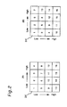
- Fig. 2 (A) shows an arrangement of the orthogonal transform coefficients output by the orthogonal transformation circuit 2
- Fig. 2 (B) shows an arrangement of the orthogonal transform coefficients rearranged by the scanning circuit 3.
- each block has a size of 4 horizontal pixels by 4 vertical pixels in each of the coefficient arrangements as shown in Figs. 2 (A) and 2 (B). Therefore, in each of Figs. 2 (A) and 2 (B), one block includes 16 coefficients composed of 4 horizontal coefficients by 4 vertical coefficients. In each of the blocks in Figs. 2 (A) and 2 (B), the coefficient have such frequence correspondence that those located leftward correspond to a horizontal low-frequency part and those located upward correspond to a vertical low-frequency part.
- the coefficients in each block are rearranged two-dimensionally in the order from the low frequency to the high frequency in so-called a zigzag scanning manner as shown in Fig. 2 (B) suitable for the coding operation in the two-dimensional orthogonal transformation.
- the above-mentioned rearrangement is adopted for the reason that the low-frequency components containing a direct current (DC) component exerts more influence on the visual sensation and therefore the low-frequency components are treated as more important components.
- DC direct current
- Fig. 3 (a) shows a distribution of orthogonal transform coefficients in a block to be input to the quantizer 7 from the scanning circuit 3, where the arrangement of the coefficients is composed of 16 coefficients corresponding to a block size of 4 x 4 pixels in the same manner as described in conjunction with Fig. 2 (B), wherein it is noted that the direct current (DC) component corresponding to number 1 of the coefficient arrangement is eliminating in Fig. 3 (a).
- DC direct current
- Fig. 3 (c) shows a distribution of the coefficients when the coefficient distribution shown in Fig. 3 (b) is decoded, where the low-frequency part is reproduced while almost the entire high-frequency part is eliminated. This means that the data amount necessary for coding each block is reduced.
- the quantization control circuit 4 judges the degree of influence on the visual sensation according to the amplitude of the direct current component of the orthogonal transform coefficients output from the orthogonal transformation circuit 2. The judgment result is output as a quantization control signal to the quantization selection circuit 8.
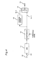
- Fig. 4 shows a constitution of the quantization control circuit 4 shown in Fig. 1.
- the data of the orthogonal transform coefficients output from the orthogonal transformation circuit 2 is entered to a terminal 10, and the direct current (DC) component thereof is entered to an absolute circuit 11 where the amplitude value of the direct current is transformed to an absolute value.
- the absolute value is compared with the threshold level in a comparator unit 12 and the compared result is outputted as a binary quantization control signal through a terminal 15.
- the direct current (DC) component of the orthogonal transform coefficients output from the orthogonal transformation circuit 2 is set in such a manner that the center of the luminance level (i.e., gray level) represents 0 (zero) level.
- the value of the DC component is variable in a range from - 256 to +255 (i.e., in a range from 0 to 256 in the absolute value thereof).
- the threshold levels are set to +200 in the 9-bit DC, when the amplitude of the DC component is below - 200 or greater than +200, it is judged that the degree of influence on the visual sensation is less (or low).
- the quantization selection circuit 8 specifies a quantization step size for compressing the orthogonal transformation coefficients output from the scanning circuit 3 in a unit of plural blocks to obtain a desired data amount for the unit of blocks.
- a relatively great quantization step size is applied to each block for which the quantization control signal represents a low degree of influence on the visual sensation and a smaller amount of coding bits are assigned. While a greater amount of coding bits are assigned to each block which represents a high degree of influence on the visual sensation in the plural blocks.
- the quantization control circuit 4 output a control signal according to the amplitude of the direct current (DC) component for each luminance signal block.
- DC direct current
- an input block corresponds to a chrominance signal
- the same control signal as applied to the luminance signal located at the same position as that of the chrominance block on the screen is adopted.
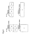
- the relation between the lumimance signal block and the chrominance signal block is as shown in Fig. 5 (a) where one chrominance signal block corresponds to four lumimance signal blocks. Therefore, when plural blocks among the blocks Y1, Y2, Y3, and Y4 as shown in Fig. 5 (a) satisfy the aforementioned condition, the chrominance signal block is quantized at a high compression ratio.
- the binary output signal of the comparator 12 according to the luminance signal is temporarily stored in a decision circuit 13, and when the chrominance signal block is input, the output of the decision circuit 13 is generated as a quantization control signal through the terminal 15 by selecting a switch 14.
- Fig. 5 (b) shows a 4 : 1 : 1 ratio signal obtained with the sampling frequency of the chrominance signal at one forth with respect to the sampling frequency of the luminance signal, where the signal is to be processed in the same manner as in the case in Fig. 5(a).
- the quantization control circuit4 the degree of influence on the visual sensation is judged with reference to the amplitude of each direct current component of the orthogonal transform coefficients thereby to detect the condition where the luminance signal has a great amplitude (approximately corresponding to pure white) as well as a small amplitude (approximately corresponding to pure black) where a low degree of influence is exerted on the visual sensation and image quality deterioration is less conspicuous.
- the quantization step size is controlled in the quantization selection circuit 8 to enable reducing the possible deterioration of image quality throughout the screen picture.
- each chrominance signal block is controlled by means of the control signal for the corresponding luminance signal in the present embodiment
- the luminance signal blocks may be only controlled without controlling any chrominance signal block to produce an effect of improving the image quality.
- each chrominance signal block It is of course easy to process each chrominance signal block in the same manner as described in connection with the luminance signal blocks.
- the amplitude of a direct current component in each chrominance signal represents chroma. Therefore, it is preferred to judge the degree of influence on the visual sensation according to the amplitude of the direct current component of a block such as a red color block of which deterioration of image quality is conspicuous to thereby control the quantization step size of the block.
- the folowing describes an orthogonal transformation encoder in accordance with a second embodiment of the present invention with reference to Figs. 6 through 9.
- the second embodiment is similar to the first embodiment and like parts are designated by the same reference numerals except a different type of quantization control circuit 20 having its structure and operation different from those of the quantization control circuit 4 in the first embodiment.
- the quantization control circuit20 of the orthogonal transformation encoder detects distribution patterns each exerting a high or low degree of influence on the visual sensation among the entire distribution patterns of the orthogonal transform coefficients output from the orthogonal transformation circuit 2 thereby to output a quantization control signal corresponding to the degree of influence on the visual sensation of each of the detected distribution pattern.
- the quantization selection circuit 8 controls the quantization step size for each block according to the degree of influence on the visual sensation represented by the quantization control signal in the same manner as described in connection with the first embodiment.
- a distribution pattern of orthogonal transform coefficients as shown in Fig. 7 is divided into two parts, a low-frequency part and a high-frequency part, by using a specified coefficient arrangement as a boundary therebetween. Then the maximum values in the low-frequency and high-frequency parts are defined as L max and H max respectively.
- the two maximum values L max and H max are each classified into one of four classes of 0, 1, 2 and 3 in the ascending order according to their absolute values.
- the absolute values are subjected to judgment whether the arrangement pattern exerts a high degree of influence on the visual sensation according to a matrix of combinations of the classes as shown in Fig. 8.
- the arrangement pattern combinations exerting a high degree of influence in the visual sensation are indicated by circle marks O.
- a pattern including orthogonal transformation coefficients having small absolute values and a pattern where coefficients range from the low-frequency part to the high-frequency part are detected, while a pattern where coefficients are concentrated on the low-frequency part is not detected.
- the quantization is carried out in such a manner that the quantization step size is reduced for each detected pattern, while the quantization step size is increased for a pattern where orthogonal transform coefficients are concentrated on the low-frequency part and the coefficients have great amplitude values.
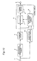
- Fig. 9 shows an exemplified structure of the quantization control circuit 20.
- the orthogonal transform coefficients output from the orthogonal transformation circuit 2 are entered to a division circuit 22 through a terminal 21 to be divided into two parts, low-frequency part and high-frequency part.
- the low and high frequency parts of the divided coefficients are respectively entered to MAX detection circuits 23 and 24 where the two maximum values L max and H max in the respective two blocks are detected.
- the two maximum values L max and H max are entered to classification circuits 25 and 26 respectively and classified according to the amplitude values thereof.
- the values of the classes output from the classification circuits 25 and 26 are judged in a decision circuit 27 using the matrix shown in Fig. 8 whether the combination of the classes in a pattern having a great degree of influence on the visual sensation.
- the judged results are generated as the control signal through a terminal 28 to be transmitted to the quantization selection circuit 8.
- the ratio of protecting the pattern detected according to the matrix i.e., the control of the quantization step size can be determined for each detected pattern.
- each distribution pattern of orthogonal transform coefficients of which deterioration is visually conspicuous is detected in the quantization control circuit 20, so that the quantization step size is controlled in the quantization selection circuit 8 according to the detected distribution pattern of the coefficients thereby to enable suppressing possible deterioration of the image quality.
- the coefficients of the low-frequency part and the coefficients of the high-frequency part may be respectively added togetherto obtain sum values thereof so that the patterns to be detected can be defined based on the relation between the sum values.
- the third embodiment is similar to the first embodiment and like parts are designated by the same reference numerals through the drawings except an arrangement of a quantization control circuit 30 directly connected to a terminal 1 which is different from that of the quantization control circuit 4 employed in the first embodiment.
- the quantization control circuit 30 detects whether an edge exists in each block according to an amplitude pattern of each input block. It is noted here that an "edge" corresponds to a boundary or outline in the screen picture.
- the quantization step size is controlled by the quantization selection circuit 8.
- the quantization selection circuit 8 reduces the quantization step size in the same manner as described in connection with the first embodiment. For example, regular quantization by a compression ratio of one fourth is changed to quantization by a compression ratio of one half.
- the distribution of the coefficient arrangement shown in Fig. 3 (d) is achieved instead of the distribution in Fig. 3 (b) which should have been achieved regularly. Therefore, the distribution of the coefficient arrangement in Fig. 3 (d) is decoded to obtain the distribution as shown in Fig. 3 (e), which means that orthogonal transform coefficients having less amount of errors than those shown in Fig. 3 (c) can be obtained to enable reducing the distortion in each block.
- Fig. 11 showing an exemplified structure of the quantization control circuit 30, the amplitude values of each block are entered to a two-dimensional BPF (band-pass-filter) 32 through a terminal 31, and then the input amplitude values of the block are subjected to band-pass-filtration by calculating means using pixels in the vicinity thereof.
- the output amplitude values of the two-dimensional BPF 32 are entered to an absolute-value circuit 33 to obtain the absolute values of the amplitude.
- the absolute values are entered to a comparator 34 where the input absolute values are compared with a threshold level to carry out judgment whether each pixel contains a high-frequency component.
- the binary output data of the comparator 34 is entered to a counter 35 where the number (N) of the pixels containing a high-frequency component in each block is counted.
- the output signal representing that an edge exists is generated through a terminal 37 to the quantization selection circuit 8. That is, the judgment that an edge exists is made when there exist high-frequency components in one block while the pixels containing the high-frequency components are not expanded in the entire part of the block.
- the possible deterioration of image quality can be reduced.
- each block to be orthogonally transformed has a size of 4 x 4 pixels in the aforementioned embodiments, each block may have a size of 8 x 8 pixels or 16 x 16 pixels. Furthermore, a three-dimensional orthogonal transformation may be adopted instead of the two dimensional orthogonal transformation in the vertical and horizontal directions.
Landscapes
- Engineering & Computer Science (AREA)
- Multimedia (AREA)
- Signal Processing (AREA)
- Compression Or Coding Systems Of Tv Signals (AREA)
Abstract
Description
- The present invention relates to an orthogonal transformation encoder for use in increasing a compression ratio in encoding a video signal with high efficiency.
- Since a video signal has a vast amount of data, a high-efficiency coding method is adapted for recording or transmitting the data. The high-efficiency coding method employs a technique of reducing the amount of data keeping the possible high quality of the image while avoiding visually conspicuous deterioration of the image quality. In line with the above technique, there is an orthogonal transform coding system as an essence of a bandwidth compression coding.
- In the orthogonal transform coding system, a screen image having a prescribed size is divided into a plurality of screen image blocks and the data of each screen image block is subjected to an orthogonal transform coding thereby to obtain orthogonal transform coefficients. Then the obtained orthogonal transform coefficients are quantized in such a manner that the method of the quantization is a decisive factor concerning the deterioration in quality of the resulting image.
- For example, according to "Adaptive Coding of Monochrome and Color Images" by Chen and Smith, IEEE Transaction on Communications Vol. COM-25, No. 11, 1987, pp. 1285 to 1292, energy of alternating current components is calculated from orthogonal transform coefficients thereby to control the bit amount for assignment based on the calculated result.
- However, according to the conventional coding method mentioned above, although the energy in each block of the screen image is reduced, the block which includes important data of such as a ground or water surface image fatally deteriorates. Furthermore, the calculation of energy of alternating current components requires a calculation of sum of squares, and therefore the above conventional coding method is not assumed to be the best one in terms of circuit scale.
- According to this invention, an orthogonal transformation encoder which receives a video signal having sampled data divided in blocks as an input comprises:
- an orthogonal transformation circuit for orthogonally transforming the input video signal divided in blocks;
- a scanning circuit for rearranging transform coefficients obtained by the orthogonal transformation circuit;
- a quantization control circuit for detecting a degree of influence on visual sensation of each block according to the transform coefficients concurrently with the operation of the scanning circuit to thereby generate a quantization control signal representing the degree of influence; and
- a coding circuit for quantizing and encoding the transform coefficients obtained by the scanning circuit according to the quantization control signal obtained by the quantization control circuit.
- The present invention provides an orthogonal transformation encoder capable of achieving a well balanced image quality throughout a screen by obtaining the degree of influence on the visual sensation for each block of the screen image in a simple manner and assigning a greater amount of data to each block which includes visually important image data than to each block in which deterioration of image quality is visually less conspicuous.
- With the construction of the orthogonal transformation encoder according to the present invention, based on the degree of influence on the visual sensation in each block, a smaller amount of codes are assigned to each block in which image quality deterioration is less conspicuous while a greater amount of codes are assigned to each block in which image quality deterioration is conspicuous, thereby enabling to control the amount of codes with improvement of the image quality throughout the screen.
- Particular embodiments of the present invention will now be described with reference to the accompanying drawings, in which:-
- Fig. 1 is a block diagram showing an orthogonal transformation encoder in accordance with a first embodiment of the present invention;
- Figs. 2 (A) and 2 (B) are views showing coefficient arrangement patterns of each block for explaining the operation of the orthogonal transformation encoder of the embodiment according to the present invention;
- Figs. 3 (a) through 3 (e) are graph views showing distribution patterns of absolute values of transform coefficients for explaining the operation of orthogonal transformation encoder of the embodiment according to the present invention;
- Fig. 4 is a block diagram showing a construction of quantization control circuit of the first embodiment of Fig. 1;
- Figs. 5 (a) and 4 (b) are schematic views showing relationships between a luminance signal and a chrominance signal in the first embodiment of the present invention;
- Fig. 6 is a block diagram showing an orthogonal transformation encoder in accordance with a second embodiment of the present invention;
- Fig. 7 is a graph view showing a distribution pattern of absolute values of transform coefficients for explaining the operation of quantization control circuit of the second embodiment of the present invention;
- Fig. 8 is a view showing combinations in a detection pattern selection for explaining the operation of the quantization control circuit of the second embodiment of the present invention;
- Fig. 9 is a block diagram showing a constitution of the quantization control circuit of the second embodiment of Fig. 6;
- Fig. 10 is a block diagram showing an orthogonal transformation encoder in accordance with a third embodiment of the present invention; and
- Fig. 11 is a block diagram showing a constitution of the quantization control circuit of the third embodiment of Fig. 10.
- Referring to Fig. 1 which shows an orthogonal transformation encoder in accordance with a first embodiment, the orthogonal transformation encoder comprises an
orthogonal transformation circuit 2 for orthogonally transforming an input video signal of sampled data divided in blocks received by aninput terminal 1 to obtain orthogonal transform coefficients. The data of the orthogonal transform coefficients output from theorthogonal transformation circuit 2 is transmitted to both ascanning circuit 3 and aquantization control circuit 4. Thescanning circuit 3 rearranges the transform coefficients obtained through theorthogonal transformation circuit 2 while thequantization control circuit 4 detects a degree of influence on the visual sensation for each block according to the transform coefficients transmitted from theorthhogonal transformation circuit 2 thereby to generate a quantization control signal to be entered to acoding circuit 5. The rearranged transform coefficients output by thescanning circuit 3 are also transmitted to thecoding circuit 5 where the rearranged transform coefficients are appropriately quantized and coded according to the quantization control signal transmitted from the quantization control circuit4, and then the resulting coded data is outputted through anoutput terminal 6. - The
coding circuit 5 comprises aquantization selection circuit 8 for specifying a quantization step size appropriate for dividing and compressing the orthogonal transform coefficients output from thescanning circuit 3 to a desired amount of coded bits according to the quantization control signal output from thequantization control circuit 4. Thecoding circuit 5 further comprises aquantizer 7 for quantizing the orthogonal transform coefficients rearranged by thescan circuit 3 with the quantization step size specified by thequantization selection circuit 8, and acoding device 9 for coding the quantized data output from thequantizer 7. Thequantization selection circuit 8 is composed of a plurality of quantizing units having various quantization step sizes different from each other, and each quantizing unit quantizes the orthogonal transform coefficients. Among the resulting data therefrom, the appropriate quantization step size is specified for compressing the orthogonal transform coefficients to a desired data amount. In addition, since the quantization control signal output from thequantization control circuit 4 represents the degree of influence on the visual sensation in each block to be subjected to quantization, therefore the quantization step size for the block is appropriately controlled by thequantization selection circuit 8 according to the quantization control signal. - Referring to Figs. 2 (A) and 2 (B) for explaining the operation of the
scanning circuit 3, wherein Fig. 2 (A) shows an arrangement of the orthogonal transform coefficients output by theorthogonal transformation circuit 2 and Fig. 2 (B) shows an arrangement of the orthogonal transform coefficients rearranged by thescanning circuit 3. - It is now assumed that the operation of the
orthogonal transformation circuit 2 is based on a two-dimensional orthogonal transformation and each block has a size of 4 horizontal pixels by 4 vertical pixels in each of the coefficient arrangements as shown in Figs. 2 (A) and 2 (B). Therefore, in each of Figs. 2 (A) and 2 (B), one block includes 16 coefficients composed of 4 horizontal coefficients by 4 vertical coefficients. In each of the blocks in Figs. 2 (A) and 2 (B), the coefficient have such frequence correspondence that those located leftward correspond to a horizontal low-frequency part and those located upward correspond to a vertical low-frequency part. In thescanning circuit 3, the coefficients in each block are rearranged two-dimensionally in the order from the low frequency to the high frequency in so-called a zigzag scanning manner as shown in Fig. 2 (B) suitable for the coding operation in the two-dimensional orthogonal transformation. The above-mentioned rearrangement is adopted for the reason that the low-frequency components containing a direct current (DC) component exerts more influence on the visual sensation and therefore the low-frequency components are treated as more important components. - Fig. 3 (a) shows a distribution of orthogonal transform coefficients in a block to be input to the
quantizer 7 from thescanning circuit 3, where the arrangement of the coefficients is composed of 16 coefficients corresponding to a block size of 4 x 4 pixels in the same manner as described in conjunction with Fig. 2 (B), wherein it is noted that the direct current (DC) component corresponding tonumber 1 of the coefficient arrangement is eliminating in Fig. 3 (a). - Now considering a case where the amplitude of a direct current (DC) component of the orthogonal transform coefficients output from the
orthogonal transformation circuit 2 is greaterthan one prescribed threshold level (approximately corresponding to pure white) or smaller than the other prescribed threshold level (approximately corresponding to pure black), image quality deterioration exerts less influence on the visual sensation, and therefore a greater quantization step size is selected to quantize the transform coefficients with increment of the compression ration in thequantizer 7. In this case, an example of the quantized coefficient distribution is shown in Fig. 3 (b). - Fig. 3 (c) shows a distribution of the coefficients when the coefficient distribution shown in Fig. 3 (b) is decoded, where the low-frequency part is reproduced while almost the entire high-frequency part is eliminated. This means that the data amount necessary for coding each block is reduced.
- When the direct current (DC) component in the orthogonal transform coefficients is not in the above-mentioned condition, that is, in case where the amplitude of a direct current component of the orthogonal transform coefficients output from the
orthogonal transformation circuit 2 is in a range between the prescribed upper and lower threshold levels, a quantization operation is carried out by selecting as smaller quantization step size without significantly increasing the compression ration in thequantizer 7. As a consequence of the quantization, a coefficient distribution is obtained as shown in Fig. 3 (d), and the obtained coefficient distribution is decoded into a coefficient distribution as shown in Fig. 3 (e). Referring to Fig. 3 (e), the data amount increases in contrast to the coefficient distribution as shown in Fig. 3 (c). However, a reproducibility up to a high-frequency part is used with less deterioration. - In other words, the
quantization control circuit 4 judges the degree of influence on the visual sensation according to the amplitude of the direct current component of the orthogonal transform coefficients output from theorthogonal transformation circuit 2. The judgment result is output as a quantization control signal to thequantization selection circuit 8. - Fig. 4 shows a constitution of the
quantization control circuit 4 shown in Fig. 1. Referring to Fig. 4, the data of the orthogonal transform coefficients output from theorthogonal transformation circuit 2 is entered to aterminal 10, and the direct current (DC) component thereof is entered to anabsolute circuit 11 where the amplitude value of the direct current is transformed to an absolute value. The absolute value is compared with the threshold level in acomparator unit 12 and the compared result is outputted as a binary quantization control signal through aterminal 15. - It is noted here that the direct current (DC) component of the orthogonal transform coefficients output from the
orthogonal transformation circuit 2 is set in such a manner that the center of the luminance level (i.e., gray level) represents 0 (zero) level. For example, in case where the DC component is 9 bis, the value of the DC component is variable in a range from - 256 to +255 (i.e., in a range from 0 to 256 in the absolute value thereof). Assuming that the threshold levels are set to +200 in the 9-bit DC, when the amplitude of the DC component is below - 200 or greater than +200, it is judged that the degree of influence on the visual sensation is less (or low). - Then the
quantization selection circuit 8 specifies a quantization step size for compressing the orthogonal transformation coefficients output from thescanning circuit 3 in a unit of plural blocks to obtain a desired data amount for the unit of blocks. In the meantime, a relatively great quantization step size is applied to each block for which the quantization control signal represents a low degree of influence on the visual sensation and a smaller amount of coding bits are assigned. While a greater amount of coding bits are assigned to each block which represents a high degree of influence on the visual sensation in the plural blocks. - The
quantization control circuit 4 output a control signal according to the amplitude of the direct current (DC) component for each luminance signal block. When an input block corresponds to a chrominance signal, the same control signal as applied to the luminance signal located at the same position as that of the chrominance block on the screen is adopted. For example, in the case of a 4 : 2 : 0 ratio signal obtained line-sequentially with the sampling frequency for the chrominance signal at one half of the sampling fre- quencyforthe luminance signal, the relation between the lumimance signal block and the chrominance signal block is as shown in Fig. 5 (a) where one chrominance signal block corresponds to four lumimance signal blocks. Therefore, when plural blocks among the blocks Y1, Y2, Y3, and Y4 as shown in Fig. 5 (a) satisfy the aforementioned condition, the chrominance signal block is quantized at a high compression ratio. - That is, referring back to Fig. 4, the binary output signal of the
comparator 12 according to the luminance signal is temporarily stored in adecision circuit 13, and when the chrominance signal block is input, the output of thedecision circuit 13 is generated as a quantization control signal through the terminal 15 by selecting aswitch 14. - Fig. 5 (b) shows a 4 : 1 : 1 ratio signal obtained with the sampling frequency of the chrominance signal at one forth with respect to the sampling frequency of the luminance signal, where the signal is to be processed in the same manner as in the case in Fig. 5(a).
- According to the first embodiment as described above, in the quantization control circuit4, the degree of influence on the visual sensation is judged with reference to the amplitude of each direct current component of the orthogonal transform coefficients thereby to detect the condition where the luminance signal has a great amplitude (approximately corresponding to pure white) as well as a small amplitude (approximately corresponding to pure black) where a low degree of influence is exerted on the visual sensation and image quality deterioration is less conspicuous. According to the above-mentioned detection operation, the quantization step size is controlled in the
quantization selection circuit 8 to enable reducing the possible deterioration of image quality throughout the screen picture. - Although each chrominance signal block is controlled by means of the control signal for the corresponding luminance signal in the present embodiment, the luminance signal blocks may be only controlled without controlling any chrominance signal block to produce an effect of improving the image quality.
- It is of course easy to process each chrominance signal block in the same manner as described in connection with the luminance signal blocks. In this case, the amplitude of a direct current component in each chrominance signal represents chroma. Therefore, it is preferred to judge the degree of influence on the visual sensation according to the amplitude of the direct current component of a block such as a red color block of which deterioration of image quality is conspicuous to thereby control the quantization step size of the block.
- The folowing describes an orthogonal transformation encoder in accordance with a second embodiment of the present invention with reference to Figs. 6 through 9. The second embodiment is similar to the first embodiment and like parts are designated by the same reference numerals except a different type of
quantization control circuit 20 having its structure and operation different from those of thequantization control circuit 4 in the first embodiment. - The quantization control circuit20 of the orthogonal transformation encoder detects distribution patterns each exerting a high or low degree of influence on the visual sensation among the entire distribution patterns of the orthogonal transform coefficients output from the
orthogonal transformation circuit 2 thereby to output a quantization control signal corresponding to the degree of influence on the visual sensation of each of the detected distribution pattern. Thequantization selection circuit 8 controls the quantization step size for each block according to the degree of influence on the visual sensation represented by the quantization control signal in the same manner as described in connection with the first embodiment. - The following describes the operation of the
quantization control circuit 20 in the second embodiment with reference to Fig. 7. A distribution pattern of orthogonal transform coefficients as shown in Fig. 7 is divided into two parts, a low-frequency part and a high-frequency part, by using a specified coefficient arrangement as a boundary therebetween. Then the maximum values in the low-frequency and high-frequency parts are defined as Lmax and Hmax respectively. The two maximum values Lmax and Hmax are each classified into one of four classes of 0, 1, 2 and 3 in the ascending order according to their absolute values. The absolute values are subjected to judgment whether the arrangement pattern exerts a high degree of influence on the visual sensation according to a matrix of combinations of the classes as shown in Fig. 8. - The arrangement pattern combinations exerting a high degree of influence in the visual sensation are indicated by circle marks O. According to the exemplified matrix shown in Fig. 8, a pattern including orthogonal transformation coefficients having small absolute values and a pattern where coefficients range from the low-frequency part to the high-frequency part are detected, while a pattern where coefficients are concentrated on the low-frequency part is not detected. Thus, the quantization is carried out in such a manner that the quantization step size is reduced for each detected pattern, while the quantization step size is increased for a pattern where orthogonal transform coefficients are concentrated on the low-frequency part and the coefficients have great amplitude values.
- Fig. 9 shows an exemplified structure of the
quantization control circuit 20. Referring to Fig. 9, the orthogonal transform coefficients output from theorthogonal transformation circuit 2 are entered to adivision circuit 22 through a terminal 21 to be divided into two parts, low-frequency part and high-frequency part. The low and high frequency parts of the divided coefficients are respectively entered toMAX detection circuits classification circuits classification circuits decision circuit 27 using the matrix shown in Fig. 8 whether the combination of the classes in a pattern having a great degree of influence on the visual sensation. The judged results are generated as the control signal through a terminal 28 to be transmitted to thequantization selection circuit 8. - It is noted that the ratio of protecting the pattern detected according to the matrix, i.e., the control of the quantization step size can be determined for each detected pattern.
- According to the second embodiment as described above, each distribution pattern of orthogonal transform coefficients of which deterioration is visually conspicuous is detected in the
quantization control circuit 20, so that the quantization step size is controlled in thequantization selection circuit 8 according to the detected distribution pattern of the coefficients thereby to enable suppressing possible deterioration of the image quality. - As a pattern detection method of the
quantization control circuit 20 of the present embodiment, the coefficients of the low-frequency part and the coefficients of the high-frequency part may be respectively added togetherto obtain sum values thereof so that the patterns to be detected can be defined based on the relation between the sum values. - The following described an orthogonal transformation encoder in accordance with a third embodiment of the present invention with reference to Figs. 10 and 11. The third embodiment is similar to the first embodiment and like parts are designated by the same reference numerals through the drawings except an arrangement of a
quantization control circuit 30 directly connected to aterminal 1 which is different from that of thequantization control circuit 4 employed in the first embodiment. - As shown in Fig. 10, the
quantization control circuit 30 detects whether an edge exists in each block according to an amplitude pattern of each input block. It is noted here that an "edge" corresponds to a boundary or outline in the screen picture. When it is judged by thequantization control circuit 30 that an edge exists, the quantization step size is controlled by thequantization selection circuit 8. In more detail, when it is judged that an edge exists in a block, thequantization selection circuit 8 reduces the quantization step size in the same manner as described in connection with the first embodiment. For example, regular quantization by a compression ratio of one fourth is changed to quantization by a compression ratio of one half. - Describing the above operation with reference to Fig. 3, the distribution of the coefficient arrangement shown in Fig. 3 (d) is achieved instead of the distribution in Fig. 3 (b) which should have been achieved regularly. Therefore, the distribution of the coefficient arrangement in Fig. 3 (d) is decoded to obtain the distribution as shown in Fig. 3 (e), which means that orthogonal transform coefficients having less amount of errors than those shown in Fig. 3 (c) can be obtained to enable reducing the distortion in each block.
- Referring to Fig. 11 showing an exemplified structure of the
quantization control circuit 30, the amplitude values of each block are entered to a two-dimensional BPF (band-pass-filter) 32 through a terminal 31, and then the input amplitude values of the block are subjected to band-pass-filtration by calculating means using pixels in the vicinity thereof. The output amplitude values of the two-dimensional BPF 32 are entered to an absolute-value circuit 33 to obtain the absolute values of the amplitude. The absolute values are entered to acomparator 34 where the input absolute values are compared with a threshold level to carry out judgment whether each pixel contains a high-frequency component. The binary output data of thecomparator 34 is entered to acounter 35 where the number (N) of the pixels containing a high-frequency component in each block is counted. The resulting counted values are entered to adecision circuit 36 for deciding whether the following condition is established:
0 < TH1 -- X -- TH2 < N
wherein X represents the counted value output by thecounter 35, TH1 and TH2 represent threshold values, and N represents the number of the pixels in each block (N=16 in the embodiment). - When the above condition is satisfied, the output signal representing that an edge exists is generated through a terminal 37 to the
quantization selection circuit 8. That is, the judgment that an edge exists is made when there exist high-frequency components in one block while the pixels containing the high-frequency components are not expanded in the entire part of the block. - According to the third embodiment as described above, by detecting an edge portion of which deterioration is conspicuous in the
quantization control circuit 30 to control the quantization step size in thequantization selection circuit 8, the possible deterioration of image quality can be reduced. - Although each block to be orthogonally transformed has a size of 4 x 4 pixels in the aforementioned embodiments, each block may have a size of 8 x 8 pixels or 16 x 16 pixels. Furthermore, a three-dimensional orthogonal transformation may be adopted instead of the two dimensional orthogonal transformation in the vertical and horizontal directions.
- In the aforementioned embodiments, there have been described several ways of managing the degree of influence on the visual sensation and otherfactors independently on each embodiment. However, it is easy to integrate the methods of the embodiments to constitute one encoder structure. For the above purpose, it is preferred to adopt as a parameter a relative increase or decrease amount of a quantization step size.
Claims (10)
Applications Claiming Priority (4)
| Application Number | Priority Date | Filing Date | Title |
|---|---|---|---|
| JP255030/91 | 1991-10-02 | ||
| JP25503091A JP2833290B2 (en) | 1991-10-02 | 1991-10-02 | Orthogonal transform coding device |
| JP275162/91 | 1991-10-23 | ||
| JP27516291A JP2913950B2 (en) | 1991-10-23 | 1991-10-23 | Orthogonal transform coding device |
Publications (3)
| Publication Number | Publication Date |
|---|---|
| EP0535963A2 true EP0535963A2 (en) | 1993-04-07 |
| EP0535963A3 EP0535963A3 (en) | 1993-12-08 |
| EP0535963B1 EP0535963B1 (en) | 1998-06-10 |
Family
ID=26541983
Family Applications (1)
| Application Number | Title | Priority Date | Filing Date |
|---|---|---|---|
| EP92308979A Expired - Lifetime EP0535963B1 (en) | 1991-10-02 | 1992-10-01 | Orthogonal transformation encoder |
Country Status (4)
| Country | Link |
|---|---|
| US (1) | US5369439A (en) |
| EP (1) | EP0535963B1 (en) |
| KR (1) | KR0137401B1 (en) |
| DE (1) | DE69225859T2 (en) |
Cited By (7)
| Publication number | Priority date | Publication date | Assignee | Title |
|---|---|---|---|---|
| EP0660619A1 (en) * | 1993-12-22 | 1995-06-28 | Laboratoires D'electronique Philips S.A.S. | Method for image variable length coding and device for carrying such method |
| EP0827346A2 (en) * | 1996-08-29 | 1998-03-04 | Fuji Xerox Co., Ltd. | Image quality prediction and control apparatus and method |
| AU693726B2 (en) * | 1995-12-27 | 1998-07-02 | Mitsubishi Denki Kabushiki Kaisha | Video coding and decoding system and method |
| WO1999031887A2 (en) * | 1997-12-16 | 1999-06-24 | Koninklijke Philips Electronics N.V. | Method of frame by frame calculation of quantization matrices |
| WO1999043163A2 (en) * | 1998-02-20 | 1999-08-26 | Koninklijke Philips Electronics N.V. | Method and device for coding a sequence of pictures |
| WO1999059342A1 (en) * | 1998-05-11 | 1999-11-18 | The University Of British Columbia | Method and system for mpeg-2 encoding with frame partitioning |
| GB2510814A (en) * | 2013-01-31 | 2014-08-20 | Canon Kk | Luma-indexed chroma sub-sampling |
Families Citing this family (29)
| Publication number | Priority date | Publication date | Assignee | Title |
|---|---|---|---|---|
| US5621760A (en) * | 1992-07-21 | 1997-04-15 | Kokusai Electric Co., Ltd. | Speech coding transmission system and coder and decoder therefor |
| JP3348310B2 (en) * | 1992-09-28 | 2002-11-20 | ソニー株式会社 | Moving picture coding method and moving picture coding apparatus |
| JP3165296B2 (en) * | 1992-12-25 | 2001-05-14 | 三菱電機株式会社 | Inter-frame coding processing method, inter-frame coding processing method, and coding control method |
| KR0127329B1 (en) * | 1993-08-14 | 1997-12-29 | 구자홍 | Buffer control apparatus for intraframe using tct |
| US5724097A (en) * | 1993-10-18 | 1998-03-03 | Mitsubishi Denki Kabushiki Kaisha | Adaptive quantization of video based on edge detection |
| US6456655B1 (en) * | 1994-09-30 | 2002-09-24 | Canon Kabushiki Kaisha | Image encoding using activity discrimination and color detection to control quantizing characteristics |
| US5937098A (en) * | 1995-02-06 | 1999-08-10 | Asahi Kogaku Kogyo Kabushiki Kaisha | Adaptive quantization of orthogonal transform coefficients for setting a target amount of compression |
| JP2789577B2 (en) * | 1995-02-07 | 1998-08-20 | 日本電気株式会社 | Addition overflow detection circuit |
| US5621465A (en) * | 1995-04-11 | 1997-04-15 | Matsushita Electric Industrial Co., Ltd. | Color image encoder |
| KR100196838B1 (en) * | 1995-12-23 | 1999-06-15 | 전주범 | Apparatus for encoding an image signal according to correlation of blocks |
| US5724096A (en) * | 1995-12-29 | 1998-03-03 | Daewoo Electronics Co., Ltd. | Video signal encoding method and apparatus employing inter-block redundancies |
| US5786856A (en) * | 1996-03-19 | 1998-07-28 | International Business Machines | Method for adaptive quantization by multiplication of luminance pixel blocks by a modified, frequency ordered hadamard matrix |
| DE69721373T2 (en) * | 1996-05-14 | 2004-04-15 | Daewoo Electronics Corp. | Quantizer for a video coding system |
| US6128339A (en) * | 1997-02-13 | 2000-10-03 | Samsung Electronics Co., Ltd. | Apparatus and method for masking video data errors |
| US6937659B1 (en) | 1997-11-14 | 2005-08-30 | Ac Capital Management, Inc. | Apparatus and method for compressing video information |
| JPH11164152A (en) * | 1997-11-26 | 1999-06-18 | Ricoh Co Ltd | Color image data compression device |
| US6459731B1 (en) * | 1998-08-28 | 2002-10-01 | Lucent Technologies Inc. | Technique for video communications using a coding-matched filter arrangement |
| US7982796B2 (en) * | 2001-03-21 | 2011-07-19 | Apple Inc. | Track for improved video compression |
| US8223844B2 (en) | 2003-11-14 | 2012-07-17 | Intel Corporation | High frequency emphasis in decoding of encoded signals |
| KR20060112447A (en) * | 2005-04-27 | 2006-11-01 | 엘지.필립스 엘시디 주식회사 | Liquid crystal injector for liquid crystal display device and injection method using thereof |
| KR100712531B1 (en) * | 2005-09-10 | 2007-04-27 | 삼성전자주식회사 | Apparatus and method for transcoding MPEG-2 data into H.264 data |
| US20110135198A1 (en) * | 2009-12-08 | 2011-06-09 | Xerox Corporation | Chrominance encoding and decoding of a digital image |
| JP5625342B2 (en) * | 2009-12-10 | 2014-11-19 | ソニー株式会社 | Image processing method, image processing apparatus, and program |
| JP5428886B2 (en) * | 2010-01-19 | 2014-02-26 | ソニー株式会社 | Information processing apparatus, information processing method, and program thereof |
| TWI401965B (en) * | 2010-06-04 | 2013-07-11 | Altek Corp | Image Compression Method with Variable Quantization Parameters |
| JP5703781B2 (en) | 2010-09-03 | 2015-04-22 | ソニー株式会社 | Image processing apparatus and method |
| BR122019025405B8 (en) * | 2011-01-13 | 2023-05-02 | Canon Kk | IMAGE CODING APPARATUS, IMAGE CODING METHOD, IMAGE DECODING APPARATUS, IMAGE DECODING METHOD AND STORAGE MEDIA |
| JP2012209673A (en) * | 2011-03-29 | 2012-10-25 | Sony Corp | Information processing apparatus, information processing method, image provision system, image provision method, and program |
| JP2013038768A (en) * | 2011-07-13 | 2013-02-21 | Canon Inc | Image encoder, image encoding method, program, image decoder, image decoding method and program |
Citations (9)
| Publication number | Priority date | Publication date | Assignee | Title |
|---|---|---|---|---|
| JPS6376687A (en) * | 1986-09-19 | 1988-04-06 | Canon Inc | Adaptation type difference encoding system |
| EP0283715A2 (en) * | 1987-03-23 | 1988-09-28 | ANT Nachrichtentechnik GmbH | Method for coding image signals |
| EP0296608A2 (en) * | 1987-06-25 | 1988-12-28 | Nec Corporation | Encoding of a picture signal in consideration of contrast in each picture and decoding corresponding to the encoding |
| JPH0276385A (en) * | 1988-09-12 | 1990-03-15 | Toshiba Corp | Picture data compressor |
| EP0368139A2 (en) * | 1988-11-05 | 1990-05-16 | ANT Nachrichtentechnik GmbH | Method for coding residual error pictures |
| JPH03140074A (en) * | 1989-10-26 | 1991-06-14 | Matsushita Electric Ind Co Ltd | Moving picture coding device |
| JPH03207190A (en) * | 1990-01-09 | 1991-09-10 | Sony Corp | High-efficiency encoding device |
| US5121216A (en) * | 1989-07-19 | 1992-06-09 | Bell Communications Research | Adaptive transform coding of still images |
| EP0500306A2 (en) * | 1991-02-21 | 1992-08-26 | Matsushita Electric Industrial Co., Ltd. | Orthogonal transformation encoder |
Family Cites Families (10)
| Publication number | Priority date | Publication date | Assignee | Title |
|---|---|---|---|---|
| JPS5992688A (en) * | 1982-11-19 | 1984-05-28 | Fuji Photo Film Co Ltd | Adaptive picture compression system |
| JP2839142B2 (en) * | 1987-11-14 | 1998-12-16 | 松下電工株式会社 | Image coding method |
| JPH02226886A (en) * | 1989-02-28 | 1990-09-10 | Sony Corp | Data transmitter |
| JPH0787586B2 (en) * | 1989-08-02 | 1995-09-20 | 富士通株式会社 | Image signal coding control method |
| FR2654285B1 (en) * | 1989-11-08 | 1992-01-31 | France Etat | DIGITAL IMAGE COMPRESSION SYSTEM BELONGING TO AN IMAGE SEQUENCE, WITH ADAPTIVE QUANTIFICATION BASED ON PSYCHOVISUAL INFORMATION. |
| DE4002912A1 (en) * | 1990-02-01 | 1991-08-08 | Ant Nachrichtentech | METHOD FOR PROCESSING IMAGE DATA, IN PARTICULAR FOR STILL IMAGE TRANSFER PURPOSES |
| JPH03247189A (en) * | 1990-02-26 | 1991-11-05 | Seiko Epson Corp | Video encoder |
| FR2660139B1 (en) * | 1990-03-23 | 1995-08-25 | France Etat | ENCODING AND TRANSMISSION METHOD FOR AT LEAST TWO QUALITY LEVELS OF DIGITAL IMAGES BELONGING TO A SEQUENCE OF IMAGES, AND CORRESPONDING DEVICES. |
| JP3001962B2 (en) * | 1990-11-13 | 2000-01-24 | 日本電気ホームエレクトロニクス株式会社 | Video data compression coding |
| DE69222332T2 (en) * | 1991-02-21 | 1998-01-29 | Nec Corp | Coding device for the compression of moving image data |
-
1992
- 1992-10-01 EP EP92308979A patent/EP0535963B1/en not_active Expired - Lifetime
- 1992-10-01 DE DE69225859T patent/DE69225859T2/en not_active Expired - Lifetime
- 1992-10-02 US US07/955,829 patent/US5369439A/en not_active Expired - Lifetime
- 1992-10-02 KR KR1019920018107A patent/KR0137401B1/en not_active IP Right Cessation
Patent Citations (9)
| Publication number | Priority date | Publication date | Assignee | Title |
|---|---|---|---|---|
| JPS6376687A (en) * | 1986-09-19 | 1988-04-06 | Canon Inc | Adaptation type difference encoding system |
| EP0283715A2 (en) * | 1987-03-23 | 1988-09-28 | ANT Nachrichtentechnik GmbH | Method for coding image signals |
| EP0296608A2 (en) * | 1987-06-25 | 1988-12-28 | Nec Corporation | Encoding of a picture signal in consideration of contrast in each picture and decoding corresponding to the encoding |
| JPH0276385A (en) * | 1988-09-12 | 1990-03-15 | Toshiba Corp | Picture data compressor |
| EP0368139A2 (en) * | 1988-11-05 | 1990-05-16 | ANT Nachrichtentechnik GmbH | Method for coding residual error pictures |
| US5121216A (en) * | 1989-07-19 | 1992-06-09 | Bell Communications Research | Adaptive transform coding of still images |
| JPH03140074A (en) * | 1989-10-26 | 1991-06-14 | Matsushita Electric Ind Co Ltd | Moving picture coding device |
| JPH03207190A (en) * | 1990-01-09 | 1991-09-10 | Sony Corp | High-efficiency encoding device |
| EP0500306A2 (en) * | 1991-02-21 | 1992-08-26 | Matsushita Electric Industrial Co., Ltd. | Orthogonal transformation encoder |
Non-Patent Citations (6)
| Title |
|---|
| ICASSP 89. MULTIDIMENSIONAL SIGNAL PROCESSING vol. 3, 23 May 1989, GLASGOW, SCOTLAND pages 1831 - 1834 , XP89232 J.W- KIM ET AL. 'Discrete Cosine Transform - Classified VQ Technique for Image Coding' * |
| ICASSP 89. MULTIDIMENSIONAL SIGNAL PROCESSING vol. 3, 23 May 1989, GLASGOW, SCOTLAND pages 1890 - 1893 , XP89247 Y.S. HO ET AL. 'Classified Transform Coding of Images Using Vector Quantization' * |
| PATENT ABSTRACTS OF JAPAN vol. 12, no. 310 (E-648)23 August 1988 & JP-A-63 076 687 ( CANON INC. ) 6 April 1988 * |
| PATENT ABSTRACTS OF JAPAN vol. 14, no. 257 (E-936)4 June 1990 & JP-A-02 076 385 ( TOSHIBA CORP. ) 15 March 1990 * |
| PATENT ABSTRACTS OF JAPAN vol. 15, no. 359 (E-1110)11 September 1991 & JP-A-03 140 074 ( MATSUSHITA ELECTRIC INDUSTRIAL CO LTD ) 14 June 1991 * |
| PATENT ABSTRACTS OF JAPAN vol. 15, no. 479 (E-1141)5 December 1991 & JP-A-03 207 190 ( SONY CORP. ) 10 September 1991 * |
Cited By (12)
| Publication number | Priority date | Publication date | Assignee | Title |
|---|---|---|---|---|
| EP0660619A1 (en) * | 1993-12-22 | 1995-06-28 | Laboratoires D'electronique Philips S.A.S. | Method for image variable length coding and device for carrying such method |
| AU693726B2 (en) * | 1995-12-27 | 1998-07-02 | Mitsubishi Denki Kabushiki Kaisha | Video coding and decoding system and method |
| EP0827346A2 (en) * | 1996-08-29 | 1998-03-04 | Fuji Xerox Co., Ltd. | Image quality prediction and control apparatus and method |
| EP0827346A3 (en) * | 1996-08-29 | 2001-01-10 | Fuji Xerox Co., Ltd. | Image quality prediction and control apparatus and method |
| WO1999031887A2 (en) * | 1997-12-16 | 1999-06-24 | Koninklijke Philips Electronics N.V. | Method of frame by frame calculation of quantization matrices |
| WO1999031887A3 (en) * | 1997-12-16 | 1999-08-19 | Koninkl Philips Electronics Nv | Method of frame by frame calculation of quantization matrices |
| WO1999043163A2 (en) * | 1998-02-20 | 1999-08-26 | Koninklijke Philips Electronics N.V. | Method and device for coding a sequence of pictures |
| WO1999043163A3 (en) * | 1998-02-20 | 1999-11-11 | Koninkl Philips Electronics Nv | Method and device for coding a sequence of pictures |
| US6295375B1 (en) | 1998-02-20 | 2001-09-25 | U.S. Philips Corporation | Method and device for coding a sequence of pictures |
| WO1999059342A1 (en) * | 1998-05-11 | 1999-11-18 | The University Of British Columbia | Method and system for mpeg-2 encoding with frame partitioning |
| GB2510814A (en) * | 2013-01-31 | 2014-08-20 | Canon Kk | Luma-indexed chroma sub-sampling |
| GB2510814B (en) * | 2013-01-31 | 2016-05-18 | Canon Kk | Luma-indexed chroma sub-sampling |
Also Published As
| Publication number | Publication date |
|---|---|
| US5369439A (en) | 1994-11-29 |
| EP0535963A3 (en) | 1993-12-08 |
| DE69225859D1 (en) | 1998-07-16 |
| DE69225859T2 (en) | 1998-12-03 |
| EP0535963B1 (en) | 1998-06-10 |
| KR0137401B1 (en) | 1998-04-27 |
| KR930009420A (en) | 1993-05-22 |
Similar Documents
| Publication | Publication Date | Title |
|---|---|---|
| US5369439A (en) | Orthogonal transform encoder using DC component to control quantization step size | |
| KR100788220B1 (en) | Quality based image compression | |
| EP0510933B1 (en) | Image processing apparatus and method | |
| US6721359B1 (en) | Method and apparatus for motion compensated video coding | |
| KR100740818B1 (en) | Variance based adaptive block size dct image compression | |
| EP0586225B1 (en) | Orthogonal transform coding apparatus and decoding apparatus | |
| KR100932412B1 (en) | Configurable Pattern Optimizer | |
| US7092445B2 (en) | Video coder providing implicit coefficient prediction and scan adaptation for image coding and intra coding of video | |
| JPH07129759A (en) | Method and device for picture processing | |
| GB2308771A (en) | Video encoding based on inter block correlation | |
| US5825422A (en) | Method and apparatus for encoding a video signal based on inter-block redundancies | |
| JP3409421B2 (en) | High efficiency coding device | |
| JP3211989B2 (en) | Orthogonal transform encoding device and decoding device | |
| JPH0774959A (en) | Image processor | |
| JPH05344348A (en) | Image encoding control method and its device | |
| Netravali et al. | Basic compression techniques | |
| JPH05130413A (en) | Coder and decoder for picture data and coding method and decoding method | |
| JPH07322298A (en) | Coder | |
| JPH06284406A (en) | Orthogonal transformation coder | |
| JPH07135671A (en) | Orthogonal transformation coder | |
| JPH06350987A (en) | Quantizer for digital picture data | |
| JPH0879532A (en) | Image encoder |
Legal Events
| Date | Code | Title | Description |
|---|---|---|---|
| PUAI | Public reference made under article 153(3) epc to a published international application that has entered the european phase |
Free format text: ORIGINAL CODE: 0009012 |
|
| 17P | Request for examination filed |
Effective date: 19921016 |
|
| AK | Designated contracting states |
Kind code of ref document: A2 Designated state(s): DE FR GB NL |
|
| PUAL | Search report despatched |
Free format text: ORIGINAL CODE: 0009013 |
|
| AK | Designated contracting states |
Kind code of ref document: A3 Designated state(s): DE FR GB NL |
|
| 17Q | First examination report despatched |
Effective date: 19960717 |
|
| GRAG | Despatch of communication of intention to grant |
Free format text: ORIGINAL CODE: EPIDOS AGRA |
|
| GRAG | Despatch of communication of intention to grant |
Free format text: ORIGINAL CODE: EPIDOS AGRA |
|
| GRAH | Despatch of communication of intention to grant a patent |
Free format text: ORIGINAL CODE: EPIDOS IGRA |
|
| GRAH | Despatch of communication of intention to grant a patent |
Free format text: ORIGINAL CODE: EPIDOS IGRA |
|
| GRAA | (expected) grant |
Free format text: ORIGINAL CODE: 0009210 |
|
| AK | Designated contracting states |
Kind code of ref document: B1 Designated state(s): DE FR GB NL |
|
| REF | Corresponds to: |
Ref document number: 69225859 Country of ref document: DE Date of ref document: 19980716 |
|
| ET | Fr: translation filed | ||
| PLBE | No opposition filed within time limit |
Free format text: ORIGINAL CODE: 0009261 |
|
| STAA | Information on the status of an ep patent application or granted ep patent |
Free format text: STATUS: NO OPPOSITION FILED WITHIN TIME LIMIT |
|
| 26N | No opposition filed | ||
| REG | Reference to a national code |
Ref country code: GB Ref legal event code: IF02 |
|
| PGFP | Annual fee paid to national office [announced via postgrant information from national office to epo] |
Ref country code: DE Payment date: 20100929 Year of fee payment: 19 |
|
| PGFP | Annual fee paid to national office [announced via postgrant information from national office to epo] |
Ref country code: GB Payment date: 20110928 Year of fee payment: 20 |
|
| PGFP | Annual fee paid to national office [announced via postgrant information from national office to epo] |
Ref country code: NL Payment date: 20111020 Year of fee payment: 20 Ref country code: FR Payment date: 20111103 Year of fee payment: 20 |
|
| REG | Reference to a national code |
Ref country code: DE Ref legal event code: R071 Ref document number: 69225859 Country of ref document: DE |
|
| REG | Reference to a national code |
Ref country code: DE Ref legal event code: R071 Ref document number: 69225859 Country of ref document: DE |
|
| REG | Reference to a national code |
Ref country code: NL Ref legal event code: V4 Effective date: 20121001 |
|
| REG | Reference to a national code |
Ref country code: GB Ref legal event code: PE20 Expiry date: 20120930 |
|
| PG25 | Lapsed in a contracting state [announced via postgrant information from national office to epo] |
Ref country code: GB Free format text: LAPSE BECAUSE OF EXPIRATION OF PROTECTION Effective date: 20120930 |