EP0535866A1 - Cabinet with rotating door - Google Patents
Cabinet with rotating door Download PDFInfo
- Publication number
- EP0535866A1 EP0535866A1 EP92308710A EP92308710A EP0535866A1 EP 0535866 A1 EP0535866 A1 EP 0535866A1 EP 92308710 A EP92308710 A EP 92308710A EP 92308710 A EP92308710 A EP 92308710A EP 0535866 A1 EP0535866 A1 EP 0535866A1
- Authority
- EP
- European Patent Office
- Prior art keywords
- door
- cabinet
- pivot arm
- arm means
- force
- Prior art date
- Legal status (The legal status is an assumption and is not a legal conclusion. Google has not performed a legal analysis and makes no representation as to the accuracy of the status listed.)
- Granted
Links
Images


Classifications
-
- E—FIXED CONSTRUCTIONS
- E06—DOORS, WINDOWS, SHUTTERS, OR ROLLER BLINDS IN GENERAL; LADDERS
- E06B—FIXED OR MOVABLE CLOSURES FOR OPENINGS IN BUILDINGS, VEHICLES, FENCES OR LIKE ENCLOSURES IN GENERAL, e.g. DOORS, WINDOWS, BLINDS, GATES
- E06B3/00—Window sashes, door leaves, or like elements for closing wall or like openings; Layout of fixed or moving closures, e.g. windows in wall or like openings; Features of rigidly-mounted outer frames relating to the mounting of wing frames
- E06B3/32—Arrangements of wings characterised by the manner of movement; Arrangements of movable wings in openings; Features of wings or frames relating solely to the manner of movement of the wing
- E06B3/34—Arrangements of wings characterised by the manner of movement; Arrangements of movable wings in openings; Features of wings or frames relating solely to the manner of movement of the wing with only one kind of movement
- E06B3/40—Arrangements of wings characterised by the manner of movement; Arrangements of movable wings in openings; Features of wings or frames relating solely to the manner of movement of the wing with only one kind of movement with a vertical or horizontal axis of rotation not at one side of the opening, e.g. turnover wings
-
- E—FIXED CONSTRUCTIONS
- E05—LOCKS; KEYS; WINDOW OR DOOR FITTINGS; SAFES
- E05D—HINGES OR SUSPENSION DEVICES FOR DOORS, WINDOWS OR WINGS
- E05D15/00—Suspension arrangements for wings
- E05D15/40—Suspension arrangements for wings supported on arms movable in vertical planes
-
- E—FIXED CONSTRUCTIONS
- E05—LOCKS; KEYS; WINDOW OR DOOR FITTINGS; SAFES
- E05F—DEVICES FOR MOVING WINGS INTO OPEN OR CLOSED POSITION; CHECKS FOR WINGS; WING FITTINGS NOT OTHERWISE PROVIDED FOR, CONCERNED WITH THE FUNCTIONING OF THE WING
- E05F1/00—Closers or openers for wings, not otherwise provided for in this subclass
- E05F1/08—Closers or openers for wings, not otherwise provided for in this subclass spring-actuated, e.g. for horizontally sliding wings
- E05F1/10—Closers or openers for wings, not otherwise provided for in this subclass spring-actuated, e.g. for horizontally sliding wings for swinging wings, e.g. counterbalance
- E05F1/1091—Closers or openers for wings, not otherwise provided for in this subclass spring-actuated, e.g. for horizontally sliding wings for swinging wings, e.g. counterbalance with a gas spring
-
- E—FIXED CONSTRUCTIONS
- E05—LOCKS; KEYS; WINDOW OR DOOR FITTINGS; SAFES
- E05Y—INDEXING SCHEME RELATING TO HINGES OR OTHER SUSPENSION DEVICES FOR DOORS, WINDOWS OR WINGS AND DEVICES FOR MOVING WINGS INTO OPEN OR CLOSED POSITION, CHECKS FOR WINGS AND WING FITTINGS NOT OTHERWISE PROVIDED FOR, CONCERNED WITH THE FUNCTIONING OF THE WING
- E05Y2900/00—Application of doors, windows, wings or fittings thereof
- E05Y2900/20—Application of doors, windows, wings or fittings thereof for furnitures, e.g. cabinets
Abstract
Description
- The present invention relates to cabinets having upwardly-movable or rotatable doors. More specifically the invention relates to cabinets with upwardly-movable, self-opening, contoured or curved doors that require little effort on the part of the user, so that the user simply begins opening the door by rotating the door upwardly a specified distance and then releasing the door, the door then continuing to the open position unassisted by the user. Furthermore, the cabinet provides greater interior space to accommodate shelves and other interior fixtures since the door is stored outside the cabinet when in the open position.
- Conveniently located and easily accessible storage space is highly desirable and often required in an office environment. In modular office furniture systems, one way of providing,storage space adjacent a work area is to mount a cabinet or shelf vertically above, and spaced apart from, a desk or work surface. Typically, such cabinets are secured to a vertical modular wall panel adjacent the work surface. This type of mounting arrangement enables the furniture designerto efficiently use storage space which ordinarily is unused, above the office worker's head.
- However, vertical mounting of storage cabinets creates certain furniture design problems. For example, when movable doors are used to conceal the contents of overhead storage cabinets, convenient means to raise and lower the door must be provided. Since the office worker must reach up and push the door upward to open the door, the door must be either relatively light in weight or provided with a balancing system to facilitate upward movement. In fact, providing a door with self-opening capabilities so that the user need only exert a minimum of effort to open the door is most desirable, especially in today's society with the ever increasing concern about providing accessible work areas to disabled workers.
- The direction of motion chosen for the door is also critical. The door can be constructed to swing into the cabinet structure or outside the structure. In known prior art, "pocket" doors are well known, and combine a hinge and drawer slide to enable the door to be swung up and then pushed on the slide into the cabinet. However, such pocket doors reduce the usable interior volume of the cabinet because the door occupies interior space when retracted. Furthermore, door structures in which the retracted door swings outside and above the cabinet structure are well known in the art. These doors provide added interior volume to the cabinet but can be heavy or cumbersome and may create extra effort by the user to open the door and swing it outside and above the cabinet. Consequently, there exists a need to provide door structures in which the retracted door swings outside and above the cabinet structure, but also is easy to open with little effort required by the user, in particular the seated or physically disabled user.
- According to the present invention, a storage cabinet having a rotating door, said cabinet comprising first and second opposed, parallel side walls, a top wall and a bottom wall, a door having opposed top and bottom edges and opposed side edges, a pair of pivot arm means for moving said door between an open position and a closed position, each of said pivot arm means including a first portion rotatably mounted adjacent one of said first and second walls and a second portion extending outwardly from said first portion and attached to said door adjacent said bottom edge thereof, so that said door is positioned above said top wall when in said open position, characterized by force means connected to said pivot arm means for both moving and counterbalancing said door as said door moves between said open and closed positions, said force means arranged to assist in movement of said door once movement of said door is initiated.
- Conveniently, a curved door is mounted adjacent its bottom edge to a pair of opposed arms which rotate on a horizontal axis and are mounted inside the cabinet adjacent opposed interior side walls. An opening mechanism for each arm is provided which is pivotably connected at one end to the arm and at the other end to a side wall of the cabinet. The opening mechanism serves a dual purpose, providing counterbalance capabilities as well as opening capabilities, whereby the cabinet door may be opened unassisted once movement is initiated by a user by initially opening the door a predetermined distance and then releasing the door which continues to an open position without any further assistance by the user.
- The invention will now be described, by way of example, with reference to the accompanying drawings, in which like reference numerals refer to like elements throughout, and in which:
- Figure 1 is a partially exploded perspective view of a cabinet shown with a mounting bracket for mounting the cabinet to a supporting wall structure.
- Figure 2 is a front elevational view of the cabinet of Figure 1 shown with the door in the raised, open position.
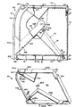
- Figure 3 is a cross-sectional view taken along line 3-3 of Figure 2, and showing the mounting bracket assembled to the cabinet.
- Figure 4 is a cross-sectional view similar to Figure 3, but showing the cabinet with the door in the raised, open position.
- Figure 5 is a cross-sectional view taken along line 5-5 of Figure 2, with parts broken away and showing the mounting bracket assembled to the cabinet.
- Figure 6 is a perspective view of a cover plate for the mounting arm shown in Figure 1.
- Figure 7 is a perspective view of the mounting arm shown in Figure 1.
- Figure 8 is a cross-sectional view taken along line 8-8 of Figure 7.
- Figure 9 is a perspective view of a spring clip for attaching a gas spring to the mounting arm and the cabinet.
- Referring to Figures 1 through 5, there is shown an embodiment of a
cabinet 100 adapted for mounting on a modularfurniture panel assembly 200 by a pair ofmounting brackets 300. - As shown in Figures 1 through 5,
cabinet 100 comprising a rectangular box having arectangular top wall 10 havingopposed side edges 10a (Figures 1 and 2), opposed front andback edges 10b and 10c (Figures 1 and 3-5), and afascia strip 10d (Figures 2-5) extending downwardly from front edge 10b; two symmetrically identical, opposed side walls 12 (Figures 1-5) each having opposed top andbottom edges back edges back edges bottom edges - Figures 3-5 disclose a
guide channel 20 secured to the lower surface oftop wall 10 intermediate front andback edges 10a and 10b, for a purpose to be described hereinafter; andrear wall 16 is provided with an inwardly formed, horizontally-elongated channel 22, for receivingmounting brackets 300. Also, each ofside walls 12 has formed therein an inwardly extending, central stud 24 (Figure 1), for a purpose to be described hereinafter. - An upwardly-movable cabinet door 30 (Figures 1 - 5) selectively provides access to the interior of
cabinet 100.Door 30 includesopposed side edges 30a (Figures 1 and 2) and opposed top andbottom edges adjacent bottom edge 30c and arcuate adjacenttop edge 30b. - Referring now to Figure 2,
cabinet 100 is shown withdoor 30 in the raised position.Cabinet 100 is provided with pluralvertical shelf brackets 40 engageable withguide channel 20, and-pluralhorizontal shelves 42 supported betweenadjacent shelf brackets 40. - The structure and operation of the upwardly
movable door 30 is operated using plural planar, rigiddoor pivot arms 50, which are pivotably mounted to the inner surfaces ofend walls 12, as will be described in greater detail hereinafter.Pivot arms 50 are fabricated of injection molded plastic, but can be fabricated of material such as sheet aluminum or sheet steel. - In the embodiment, two
pivot arms 50 are provided, one at each ofsides 30a ofdoor 30.Pivot arms 50 serve to movably connectsides 30a ofdoor 30 toend walls 12 ofcabinet 100 while restricting the movement ofdoor 30 to an arcuate path. In Figure 2, eacharm 50 is positioned immediately adjacent one ofend walls 12. This arrangement ensures that a minimum of interior cabinet space is occupied by the door operating mechanism. - Figures 3-8
show arm 50 comprising acircular disk portion 52 integrally formed with atangential arm portion 54 and amounting bracket 56. Thearm portion 54 has a substantially linearfirst side 54a formed as a tangent ofdisk portion 52; an L-shapedsecond side 54b a portion of which is parallel tofirst side 54a and a portion of which is substantially perpendicular tofirst side 54a; anouter end 54c which joins first andsecond sides inner end 54d which is coextensive with the circumference ofdisk portion 52.Side 54a forms an angle of approximately 45° withouter end 54c. -
Mounting bracket 56 extends perpendicularly fromtangential arm portion 54 inwardly ofouter end 54c for mountingpivot arm 50 todoor 30adjacent bottom edge 30c. Thus, whendoor 30 is closed as shown in Figures 3 and 5,side 54a is arranged at an angle of approximately 45° relative to horizontal.Mounting bracket 56 is formed integrally withtangential arm portion 54. Also,door 30 can be mounted to mountingbracket 56 by conventional screws inserted through threaded apertures 56a inmounting bracket 56. - A gas
spring mounting pin 58 extends perpendicularly from aprotrusion 54e onside 54a,adjacent disk portion 52.Mounting pin 58 is inserted intoprotrusion 54e during the injection molding process. -
Disk portion 52 is provided with acentral boss 60 for receiving stud 24 positioned on the inside of each ofend walls 12 ofcabinet 100, by which each ofarms 50 is mounted on itsrespective end wall 12 and about which each ofarms 50 pivots. - The
door 30 is counterbalanced by force providing means in the form of agas spring 70 comprising acylinder 72 provided with a reciprocating piston (not shown) andpiston rod 74, and having a cylinder end and a rod end. For example, doors having a nominal width of 24, 30, 33, 36, 42 and 48 inches respectively employ a pair of gas springs exerting a force of 15,19, 22, 24, 31 and 33 psi respectively. Thegas spring 70 serves a dual purpose, acting both as a means to counterbalance the weight ofdoor 30 and as a means of openingdoor 30 unassisted once the user initiates the opening ofdoor 30 by rotating the door to an angle of approximately 15 to 20 degrees and then releasing the door. - At its cylinder end, the
gas spring 70 is provided with acylinder clevis 76 for pivotably connectingcylinder 72 to mountingpin 54e ofarm 50; while at its rod end, it is provided with arod clevis 78 for pivotably connectingpiston rod 74 to a fixed mounting bracket or stud 80 (Figures 3-5) positioned at the lower rear corner of each ofend walls 12. - The
gas spring 70 is secured to mountingpin 58 ofarm 50 and to mountingbracket 80 onend wall 12 bysmall spring clips 82, shown in Figure 9, which slide overclevises pin 58 and mountingbracket 80, respectively.Suitable spring clips 82 are commercially available as part no. PC 119 from AVM, Inc. of Marion, South Carolina. - The rod end of the
gas spring 70 is positioned facing downwardly, with the cylinder end facing upwardly, to keep the oil incylinder 72 on the cylinder seal (not shown), to extend the life expectancy of the gas. - The
gas springs 70 are designed to assist thedoor 30 in opening after they have rotated approximately 15-20 degrees. The gas springs 70 also provide a closing assist feature so that the user need only exert limited force to overcome the force of the gas spring to close the door at a controlled rate rather than slamming shut. The motion ofdoor 30 is curtailed at the top of its arc by striking a against sound- deadening bumper 94 (Figure 6). - By using the
arm 50 in conjunction with thegas spring 70, thearm 50 can be made visually appealing and thegas spring 70 does not have to be mounted directly todoor 30. Further,cover panels 90 can be provided at each ofend walls 12, as shown in Figures 2 and 5, to conceal the gas springs 70 and most of thepivot arms 50. - Although only one
cover panel 90 is shown in detail, in Figure 6, it should be understood that thecover panels 90 at either side of cabinet 100 (as shown in Figure 2) are mirror images of each other. Referring now to Figures 5 and 6, each ofcover panels 90 is rectangular in shape, having a side wall 90a, and projecting outwardly from side wall 90a a top wall 90b, arear wall 90c, a bottom wall 90d, and afront wall 90e. Although eachcover panel 90 is rectangular,front wall 90e is connected to top wall 90b by anarcuate corner portion 90f parallel to the arcuate profile ofdoor 30. -
Front wall 90e andarcuate corner portion 90f have acontinuous notch 90g formed at the edge thereof along substantially its entire length, to provide clearance forarm 50 as it moves between the open and closed position. Also, top wall 90b has aninset portion 90h spaced rearwardly fromarcuate corner portion 90f, for receivingguide channel 20; and the corner formed by top wall 90b andrear wall 90c defines an inset 90i, for receivingelongated channel 22. Bottom wall 90d has anotch 90j formed therein adjacentrear wall 90c, to provide clearance forpiston rod 74 ofgas spring 70, as shown in Figure 5. - Side wall 90a is provided with a
central boss 90k for receiving a flat-head screw 92 for securing eachcover panel 90 andpivot arm 50 to itsrespective end wall 12. Upper and lower, substantially V-shaped reinforcingribs ribs respective insets 90n and 90o for receiving upper andlower bumpers bumpers door 30. -
Cover panel 90 also is provided with a central, inwardly-projectingboss 90k as shown in Figure 6 which registers withboss 60 ofarm 50 and stud 24 ofside wall 12, for attachingcover panel 90 toside wall 12. Preferably, coverpanels 90 are injection molded plastic and are fastened to studs 24 by flat head machine screws 92.Cover panels 90 are removable to provide for quick field replacement of adefective gas spring 70. - When the
cabinet door 30 is moved upwardly to an angle of rotation of approximately 15 to 20 degrees using manual force,arm 50 rotates aroundboss 60, causingcylinder 72 andpiston rod 74 to move apart relative to one another as they rotate respectively atclevises gas spring 70 is only slightly offset from thecenter 60 ofdisk portion 52 ofarm 50 when the door is in a closed position. In this closed position the force generated bygas spring 70 is restrained since it is substantially directed through the pivot point. When the door is manually opened approximately 15 to 20 degrees, the pivot point betweengas spring 70 andarm 50 moves slightly forward of the cabinet causing the force generated bygas spring 70 to now be essentially tangential to rotatably mounteddisk 52. Thus, when the user initiates movement ofcabinet door 30, the user may then releasedoor 30 permittingdoor 30 to move for the remainder of its travel solely under the force ofgas spring 70. The moving apart motion ofcylinder 72 andpiston rod 74 at a controlled rate provides a smooth continuingmotion enabling door 30 to open completely without any further effort by the user. - The rotatable arms can also be used to rotatably mount a door in an article of furniture other than the cabinets described herein, or to rotatably mount articles other than a door. Also; the rotatable arms can be used to mount rotatable, side-by-side doors in a cabinet.
Claims (12)
Applications Claiming Priority (4)
| Application Number | Priority Date | Filing Date | Title |
|---|---|---|---|
| US76610391A | 1991-09-27 | 1991-09-27 | |
| US766103 | 1991-09-27 | ||
| US93763392A | 1992-08-28 | 1992-08-28 | |
| US937633 | 1992-08-28 |
Publications (2)
| Publication Number | Publication Date |
|---|---|
| EP0535866A1 true EP0535866A1 (en) | 1993-04-07 |
| EP0535866B1 EP0535866B1 (en) | 1997-04-09 |
Family
ID=27117688
Family Applications (1)
| Application Number | Title | Priority Date | Filing Date |
|---|---|---|---|
| EP19920308710 Expired - Lifetime EP0535866B1 (en) | 1991-09-27 | 1992-09-24 | Cabinet with rotating door |
Country Status (3)
| Country | Link |
|---|---|
| EP (1) | EP0535866B1 (en) |
| CA (1) | CA2079184A1 (en) |
| DE (1) | DE69218868T2 (en) |
Cited By (7)
| Publication number | Priority date | Publication date | Assignee | Title |
|---|---|---|---|---|
| AT501065A1 (en) * | 2004-11-18 | 2006-06-15 | Blum Gmbh Julius | ACTUATOR FOR MOVING A FURNITURE FLAP |
| EP2093361A2 (en) * | 2008-02-25 | 2009-08-26 | Heinrich J. Kesseböhmer KG | Attachment device |
| US7694459B2 (en) | 2004-11-18 | 2010-04-13 | Julius Blum Gmbh | Spring loaded actuating arm for moving a flap of a piece of furniture |
| GB2479027A (en) * | 2010-03-22 | 2011-09-28 | Harte Woodworking Ltd | A storage drawer with a hinged cover biased to a closed position |
| CN103742038A (en) * | 2014-01-26 | 2014-04-23 | 广东名门锁业有限公司 | Side-hung lateral turnover door |
| EP2843179A1 (en) * | 2013-09-03 | 2015-03-04 | Roma Kg | Roller shutter box assembly, shutter box wall profile and supplementary profile |
| DE102018112871A1 (en) * | 2018-05-29 | 2019-12-05 | Paul Hettich Gmbh & Co. Kg | Furniture |
Families Citing this family (1)
| Publication number | Priority date | Publication date | Assignee | Title |
|---|---|---|---|---|
| CN113749425B (en) * | 2021-09-15 | 2022-11-04 | 浙江星星冷链集成股份有限公司 | Vaccine cabinet with good sealing performance |
Citations (4)
| Publication number | Priority date | Publication date | Assignee | Title |
|---|---|---|---|---|
| FR1344373A (en) * | 1962-10-15 | 1963-11-29 | Bathroom cabinet | |
| FR2065203A5 (en) * | 1969-12-15 | 1971-07-23 | Tielsa Moebel Werke Gmbh | |
| FR2089842A5 (en) * | 1970-04-29 | 1972-01-07 | Stanley Works Gmbh | |
| FR2091715A5 (en) * | 1970-05-13 | 1972-01-14 | Hettich F Kg |
-
1992
- 1992-09-24 EP EP19920308710 patent/EP0535866B1/en not_active Expired - Lifetime
- 1992-09-24 DE DE1992618868 patent/DE69218868T2/en not_active Expired - Lifetime
- 1992-09-25 CA CA 2079184 patent/CA2079184A1/en not_active Abandoned
Patent Citations (4)
| Publication number | Priority date | Publication date | Assignee | Title |
|---|---|---|---|---|
| FR1344373A (en) * | 1962-10-15 | 1963-11-29 | Bathroom cabinet | |
| FR2065203A5 (en) * | 1969-12-15 | 1971-07-23 | Tielsa Moebel Werke Gmbh | |
| FR2089842A5 (en) * | 1970-04-29 | 1972-01-07 | Stanley Works Gmbh | |
| FR2091715A5 (en) * | 1970-05-13 | 1972-01-14 | Hettich F Kg |
Cited By (8)
| Publication number | Priority date | Publication date | Assignee | Title |
|---|---|---|---|---|
| AT501065A1 (en) * | 2004-11-18 | 2006-06-15 | Blum Gmbh Julius | ACTUATOR FOR MOVING A FURNITURE FLAP |
| US7694459B2 (en) | 2004-11-18 | 2010-04-13 | Julius Blum Gmbh | Spring loaded actuating arm for moving a flap of a piece of furniture |
| EP2093361A2 (en) * | 2008-02-25 | 2009-08-26 | Heinrich J. Kesseböhmer KG | Attachment device |
| EP2093361A3 (en) * | 2008-02-25 | 2014-03-19 | Kesseböhmer Holding e.K. | Attachment device |
| GB2479027A (en) * | 2010-03-22 | 2011-09-28 | Harte Woodworking Ltd | A storage drawer with a hinged cover biased to a closed position |
| EP2843179A1 (en) * | 2013-09-03 | 2015-03-04 | Roma Kg | Roller shutter box assembly, shutter box wall profile and supplementary profile |
| CN103742038A (en) * | 2014-01-26 | 2014-04-23 | 广东名门锁业有限公司 | Side-hung lateral turnover door |
| DE102018112871A1 (en) * | 2018-05-29 | 2019-12-05 | Paul Hettich Gmbh & Co. Kg | Furniture |
Also Published As
| Publication number | Publication date |
|---|---|
| EP0535866B1 (en) | 1997-04-09 |
| DE69218868T2 (en) | 1997-09-18 |
| DE69218868D1 (en) | 1997-05-15 |
| CA2079184A1 (en) | 1993-03-28 |
Similar Documents
| Publication | Publication Date | Title |
|---|---|---|
| US5409308A (en) | Overhead cabinet with rotating door | |
| US5172969A (en) | Overhead cabinet with rotating door | |
| JP4891935B2 (en) | Storage unit | |
| US7959241B2 (en) | Pullout structure for cabinet | |
| US8083303B2 (en) | Built-in sliding rotating element for modular corner cabinets | |
| RU2416062C2 (en) | Door for domestic appliance | |
| AU2012355972B2 (en) | Cabinets and mirrors selectively mounted on hinges supporting roomdoors on door frames, hinges for such mountings, and methods for so mounting | |
| EP1123453B1 (en) | Storage bin with counterbalanced door | |
| US6574835B2 (en) | Hinge for an over-head storage compartment having non-centered pivoting motion | |
| US20030093877A1 (en) | Hinge for furniture | |
| US20090295262A1 (en) | Soft close drawer assembly | |
| US6026752A (en) | Operative plate for a switch cubicle | |
| EP0535866B1 (en) | Cabinet with rotating door | |
| EP0841459B1 (en) | Overhead storage cabinet | |
| US6227635B1 (en) | Storage cabinet with handle operated door | |
| CN110573044A (en) | Cabinet | |
| US5938306A (en) | Cabinet and door assembly | |
| CA3030593C (en) | Damper device | |
| US6634727B2 (en) | Closet doors with integrated shelves | |
| US6220681B1 (en) | Armoire with built in desk | |
| US11659924B2 (en) | Multi-level cabinet storage system | |
| US6007171A (en) | Cabinet with over-the-top door | |
| JP4066188B2 (en) | Skeletal structural member with door | |
| US5860717A (en) | Drawer stop device | |
| JP2546493Y2 (en) | Hanging cabinet |
Legal Events
| Date | Code | Title | Description |
|---|---|---|---|
| PUAI | Public reference made under article 153(3) epc to a published international application that has entered the european phase |
Free format text: ORIGINAL CODE: 0009012 |
|
| AK | Designated contracting states |
Kind code of ref document: A1 Designated state(s): DE FR GB IT |
|
| 17P | Request for examination filed |
Effective date: 19930924 |
|
| 17Q | First examination report despatched |
Effective date: 19950809 |
|
| GRAG | Despatch of communication of intention to grant |
Free format text: ORIGINAL CODE: EPIDOS AGRA |
|
| GRAH | Despatch of communication of intention to grant a patent |
Free format text: ORIGINAL CODE: EPIDOS IGRA |
|
| GRAH | Despatch of communication of intention to grant a patent |
Free format text: ORIGINAL CODE: EPIDOS IGRA |
|
| GRAH | Despatch of communication of intention to grant a patent |
Free format text: ORIGINAL CODE: EPIDOS IGRA |
|
| GRAH | Despatch of communication of intention to grant a patent |
Free format text: ORIGINAL CODE: EPIDOS IGRA |
|
| RAP1 | Party data changed (applicant data changed or rights of an application transferred) |
Owner name: KNOLL, INC. |
|
| GRAA | (expected) grant |
Free format text: ORIGINAL CODE: 0009210 |
|
| AK | Designated contracting states |
Kind code of ref document: B1 Designated state(s): DE FR GB IT |
|
| ITF | It: translation for a ep patent filed |
Owner name: 0508;05TOFJACOBACCI & PERANI S.P.A. |
|
| REF | Corresponds to: |
Ref document number: 69218868 Country of ref document: DE Date of ref document: 19970515 |
|
| ET | Fr: translation filed | ||
| PLBE | No opposition filed within time limit |
Free format text: ORIGINAL CODE: 0009261 |
|
| STAA | Information on the status of an ep patent application or granted ep patent |
Free format text: STATUS: NO OPPOSITION FILED WITHIN TIME LIMIT |
|
| 26N | No opposition filed | ||
| REG | Reference to a national code |
Ref country code: GB Ref legal event code: IF02 |
|
| PGFP | Annual fee paid to national office [announced via postgrant information from national office to epo] |
Ref country code: DE Payment date: 20100929 Year of fee payment: 19 |
|
| PGFP | Annual fee paid to national office [announced via postgrant information from national office to epo] |
Ref country code: IT Payment date: 20100928 Year of fee payment: 19 |
|
| PGFP | Annual fee paid to national office [announced via postgrant information from national office to epo] |
Ref country code: GB Payment date: 20110926 Year of fee payment: 20 Ref country code: FR Payment date: 20111005 Year of fee payment: 20 |
|
| REG | Reference to a national code |
Ref country code: DE Ref legal event code: R071 Ref document number: 69218868 Country of ref document: DE |
|
| REG | Reference to a national code |
Ref country code: DE Ref legal event code: R071 Ref document number: 69218868 Country of ref document: DE |
|
| REG | Reference to a national code |
Ref country code: GB Ref legal event code: PE20 Expiry date: 20120923 |
|
| PG25 | Lapsed in a contracting state [announced via postgrant information from national office to epo] |
Ref country code: DE Free format text: LAPSE BECAUSE OF EXPIRATION OF PROTECTION Effective date: 20120925 Ref country code: GB Free format text: LAPSE BECAUSE OF EXPIRATION OF PROTECTION Effective date: 20120923 |