EP0528759B1 - Dispositif d'entraînement d'un ensemble pour faire des infusions dans une machine à café - Google Patents
Dispositif d'entraînement d'un ensemble pour faire des infusions dans une machine à café Download PDFInfo
- Publication number
- EP0528759B1 EP0528759B1 EP92810575A EP92810575A EP0528759B1 EP 0528759 B1 EP0528759 B1 EP 0528759B1 EP 92810575 A EP92810575 A EP 92810575A EP 92810575 A EP92810575 A EP 92810575A EP 0528759 B1 EP0528759 B1 EP 0528759B1
- Authority
- EP
- European Patent Office
- Prior art keywords
- brewing
- drive
- spindle
- drive spindle
- cylinder
- Prior art date
- Legal status (The legal status is an assumption and is not a legal conclusion. Google has not performed a legal analysis and makes no representation as to the accuracy of the status listed.)
- Expired - Lifetime
Links
Images

Classifications
-
- A—HUMAN NECESSITIES
- A47—FURNITURE; DOMESTIC ARTICLES OR APPLIANCES; COFFEE MILLS; SPICE MILLS; SUCTION CLEANERS IN GENERAL
- A47J—KITCHEN EQUIPMENT; COFFEE MILLS; SPICE MILLS; APPARATUS FOR MAKING BEVERAGES
- A47J31/00—Apparatus for making beverages
- A47J31/24—Coffee-making apparatus in which hot water is passed through the filter under pressure, i.e. in which the coffee grounds are extracted under pressure
- A47J31/34—Coffee-making apparatus in which hot water is passed through the filter under pressure, i.e. in which the coffee grounds are extracted under pressure with hot water under liquid pressure
- A47J31/36—Coffee-making apparatus in which hot water is passed through the filter under pressure, i.e. in which the coffee grounds are extracted under pressure with hot water under liquid pressure with mechanical pressure-producing means
- A47J31/3604—Coffee-making apparatus in which hot water is passed through the filter under pressure, i.e. in which the coffee grounds are extracted under pressure with hot water under liquid pressure with mechanical pressure-producing means with a mechanism arranged to move the brewing chamber between loading, infusing and ejecting stations
- A47J31/3609—Loose coffee being employed
- A47J31/3614—Means to perform transfer from a loading position to an infusing position
-
- A—HUMAN NECESSITIES
- A47—FURNITURE; DOMESTIC ARTICLES OR APPLIANCES; COFFEE MILLS; SPICE MILLS; SUCTION CLEANERS IN GENERAL
- A47J—KITCHEN EQUIPMENT; COFFEE MILLS; SPICE MILLS; APPARATUS FOR MAKING BEVERAGES
- A47J31/00—Apparatus for making beverages
- A47J31/24—Coffee-making apparatus in which hot water is passed through the filter under pressure, i.e. in which the coffee grounds are extracted under pressure
- A47J31/34—Coffee-making apparatus in which hot water is passed through the filter under pressure, i.e. in which the coffee grounds are extracted under pressure with hot water under liquid pressure
- A47J31/36—Coffee-making apparatus in which hot water is passed through the filter under pressure, i.e. in which the coffee grounds are extracted under pressure with hot water under liquid pressure with mechanical pressure-producing means
- A47J31/3604—Coffee-making apparatus in which hot water is passed through the filter under pressure, i.e. in which the coffee grounds are extracted under pressure with hot water under liquid pressure with mechanical pressure-producing means with a mechanism arranged to move the brewing chamber between loading, infusing and ejecting stations
- A47J31/3609—Loose coffee being employed
Definitions
- the present invention relates to a drive device for a brewing device of a coffee machine according to the preamble of claim 1.
- the preparation of coffee with coffee machines is carried out according to different processes, which can be divided into two basic types.
- the present invention relates in particular to the last-mentioned pressure brewing process.
- Various devices are already known for automatically carrying out this method.
- these known coffee machines differ in their construction, in particular with regard to robustness, flexibility in the course of the process, ease of operation and maintenance, etc.
- Such coffee machines usually consist of a brewing device and a more or less complex mechanism for driving the moving parts of the brewing device. Efforts are being made to provide a single drive element in a coffee machine and thus all the moving parts of the brewing device to drive via the mechanism mentioned.
- EP-A-0 154 206 discloses a coffee machine which is constructed according to the principles described above, wherein all parts of the machine which are subject to contamination, essentially the entire brewing device, are combined with the drive mechanism to form a push-in component, wherein this component is operatively connected to the single drive element via coupling means.
- the mechanism for driving the individual parts of the brewing device comprises several drive linkages with slots, cams and grooves and is consequently constructed accordingly. Despite the removable component, cleaning the various grooves and slots from any coffee powder that may be stuck in them is not entirely easy.
- the preferred embodiment in which several brewing devices can be driven via the same and only drive device, comprises the features of the dependent claim 2.
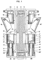
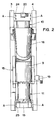
- FIG. 1 each show two brewing devices 2, 2 'of a coffee machine in a partial longitudinal section viewed from the side (Fig. 1), in a front view, in which only one of the brewing devices 2 is visible (Fig. 2nd ) and in a top view (Fig. 3), each in the filling position.
- Fig. 1 the most important functional components of the brewing devices 2, 2 'and the drive device 1 according to the invention are shown.
- the reference numerals of corresponding parts of a brewing device 2 are in the other of the brewing devices 2 'each provided with a line. It is tacitly assumed in the following description that what has been said for each part of the one brewing device 2, without being particularly mentioned, also applies to the corresponding part of the other brewing device 2 '.
- the brewing devices 2, 2 ' are mounted on a frame which essentially has a first and a second side cheek 3, 4, which side cheeks run parallel to one another by being spaced apart by appropriate spacing means.
- a drive spindle 5 extends approximately over the entire length of the two side cheeks 3, 4.
- Each one end of the drive spindle 5 is in a first or upper spindle bearing 6 or in a second or lower spindle bearing 7 rotatably and at the same time secured against longitudinal displacement.
- Each of the mentioned spindle bearings 6, 7 has expansions toward the two side cheeks 3, 4, to which the side cheeks are fastened.
- the spindle bearings 6, 7 serve simultaneously as a spacer of the two side cheeks 3, 4.
- Each of the brewing devices 2, 2 'each comprises a first or upper piston 10, 10', which is immovably connected to the two side cheeks 3, 4.
- a second or lower piston 11, 11' is arranged in a substantially hollow cylindrical brewing cylinder 9, 9 '.
- the lower piston 11, 11 ' is held within its brewing cylinder 9, 9' longitudinally movable.
- the second piston 11, 11 ' comprises a hollow cylindrical shaft 12, 12', each extending from the brewing cylinder 9, 9 '.
- first and second stop means 21, 21', 22, 22 ' which are intended to limit the displacement movement of the second piston 11, 11' within the brewing cylinder 9, 9 '.
- Each of the second pistons 11, 11 ' is pushed with its hollow cylindrical shaft 12, 12' over a stub 13, 13 'held immovably between said side cheeks 3, 4'.
- O-rings 14, 14 ' are inserted into the grooves provided.
- Each of the O-rings 14, 14 'facing away from the nozzle 13, 13' has sideways against the side cheeks 3, 4 directed extensions 25 on which the connecting pieces are connected to the side cheeks.
- Each of the brewing devices 9, 9 'facing away from the end of the first pistons 10, 10' is provided with equivalent lateral extensions 24, 24 ', which are intended for fastening said piston between the side cheeks 3, 4.
- the extensions 24, 24 ', 25, 25' also serve to keep the side walls 3, 4 at the desired distance.
- Each one in the area of the first pistons 10, 10 'pivotally arranged filling funnel 16, 16' is used for filling coffee powder into the brewing cylinders 9, 9 '.
- Each of these brewing cylinders 9, 9 ' has a driving element 17, 17' directed against the drive spindle 5.
- the hollow cylindrical drive spindle 5 is provided with a first guide means 8 on its outer surface.
- Each of the entrainment members 17, 17 ' which essentially has the shape of a sector-shaped section of a hollow cylinder, has on the side facing away from its associated brewing cylinder 9, 9' in the figures second guide means which are not visible and which correspond to the first guide means 8 in such a way, that when the drive spindle 5 rotates in one direction or the other, the brewing cylinders 9, 9 'are displaced towards one or the other end of the drive spindle 5. To reach a brewing position, they are displaceable toward the first pistons 10, 10 '.
- the brewing cylinders 9, 9' slide over the first pistons 10, 10 ', a brewing chamber being formed in each of the brewing cylinders.
- the shaft 12, 12 ' has been lifted off its associated connecting piece 13, 13' during this displacement movement.
- Hot water becomes passed under pressure via the first connection nipple 19, 19 'into the brewing chambers and flows through the coffee powder present in the latter.
- the coffee produced is derived via the second connection nipple 20, 20 '.
- the drive device according to the invention which comprises the drive spindle 5 already mentioned and the driving element 17, 17 'of each of the brewing devices 2, 2', also has a drive shaft 18 which is grooved longitudinally on an end facing the drive spindle 5, the grooves of the drive shaft 18 can be inserted into appropriately designed grooves which are distributed around the inner circumference of the hollow cylindrical drive spindle 5.
- the other end of the drive shaft 18, which is not visible in the figures, is connected to a drive motor.
- Each of the driving elements 17, 17 ' is designed so that it comprises at most half of the peripheral circumference of the drive spindle 5.
- the first guide means is advantageously a Multi-start spindle thread 8 formed, which extends helically substantially over the entire length of the drive spindle 5, which is limited by the spindle bearings 6, 7.
- the second guide means which are arranged on the spindle thread 8 facing surface of the driving elements 17, 17 ', comprise in this preferred embodiment with the spindle thread 8 cooperating partial threads of an internal thread.
- the pitch of the spindle thread 8 is chosen so that, as a result of the thread friction when brewing the coffee under pressure with the drive spindle 5 not braked, there is no reset movement of the brewing cylinders 9, 9 '.
- the driving elements 17, 17 ' are arranged on the brewing cylinders 9, 9' in the direction of the brewing cylinder axes 27, 27 'longitudinally displaceable. This is necessary to compensate for the thread pitch of the spindle thread 8 of brewing devices 2, 2 'arranged around the circumference of the drive spindle 5, as indicated by the reference numerals 23, 23'.
- a compensation of the slope of the spindle thread 8 could also take place in that the extensions 24, 24 'of the first pistons 10, 10' and 25, 25 'of the connecting pieces 13, 13' which are executed sideways to the side cheeks 3, 4 'of the side cheeks 3 , 4 would each be slidable in the longitudinal direction. This possibility is indicated in FIG. 2 by the dashed arrows A.
- the brewing devices 2, 2 'shown in Figures 1 to 3', the brewing cylinder axes 27, 27 'parallel to the axis 26 of the drive spindle 5, preferably have a vertical operating position. If only two brewing devices were arranged, it would also be possible to select a horizontal or inclined position as the operating position for the axes mentioned. The two brewing devices would be in the former Case arranged side by side. The filling of the coffee powder in the brewing cylinder 9, 9 'would have to be adapted constructively.
- the drive device according to the invention is also suitable if one of the brewing devices 2 'were omitted in the exemplary embodiment described above. It is also possible, as indicated in FIG. 4, which shows a top view of a further exemplary embodiment, to arrange more than two brewing devices evenly distributed around the circumference of the drive spindle 5. 4, a total of four brewing devices 2, 2 ', 2 ⁇ , 2 ′′′ are provided. Each of these brewing devices has a drive element facing the drive spindle 17, 17 ', 17 ⁇ , 17 ′′′. Each of these driving elements is provided on the side facing the drive spindle with partial threads which are in engagement with the spindle thread 8. With four brewing devices, each of the entrainment members 17, 17 ', 17 ⁇ , 17 ⁇ comprises the peripheral circumference of the drive spindle 5 at most to a quarter, that is, at most to the reciprocal value of the number of brewing devices.
- the drive element (s) do not fully encompass the drive spindle, they can be produced simply and inexpensively using plastic injection molding technology. This construction also has the great advantage of a self-cleaning effect. Faults due to thread contamination due to adhering coffee powder can thus be avoided.
Landscapes
- Engineering & Computer Science (AREA)
- Mechanical Engineering (AREA)
- Food Science & Technology (AREA)
- Apparatus For Making Beverages (AREA)
Claims (6)
- Dispositif d'actionnement pour un dispositif d'infusion (2) d'une machine à café avec un bâti (3, 4), une vis d'entraînement (5) liée au bâti de manière à pouvoir pivoter avec au moins un premier moyen de guidage (8) s'étendant comme un filetage pour l'essentiel sur toute la longueur de la vis d'entraînement (5), le dispositif d'infusion (2) comprenant un cylindre d'infusion (9) et deux pistons (10, 11) formant une chambre d'infusion, le cylindre d'infusion (9) et les pistons (10, 11) étant déplaçables les uns par rapport aux autres dans l'axe du cylindre d'infusion (27), la vis d'entraînement (5) s'étendant parallèlement à l'axe du cylindre d'infusion (27), caractérisé par un organe d'entraînement (17) avec un deuxième moyen de guidage prévu sur le cylindre d'infusion (9), l'organe d'entraînement étant engagé dans le premier moyen de guidage (8) de la vis d'entraînement (5) et entourant au maximum la moitié de la périphérie de la vis d'entraînement.
- Dispositif d'actionnement selon la revendication 1, caractérisé par plusieurs dispositifs d'infusion (2, 2') répartis autour de la périphérie de la vis d'entraînement (5), l'organe d'entraînement (17, 17') de chacun des dispositifs d'infusion (2, 2') entourant au maximum la partie de la périphérie de la vis d'entraînement (5) correspondant à l'inverse du nombre des dispositifs d'infusion (2, 2').
- Dispositif d'actionnement selon la revendication 1 ou 2, caractérisé en ce que le premier moyen de guidage est un filetage externe (8) et en ce que l'organe d'entraînement (17, 17') présente pour l'essentiel la forme d'un tronçon sectoriel de cylindre creux et est muni d'un filetage partiel interne avec un pas de filetage correspondant au filetage externe (8).
- Dispositif d'actionnement selon l'une des revendications 1 à 3, caractérisé en ce que l'organe d'entraînement (17, 17') est lié de manière non permanente au cylindre d'infusion (9, 9') et est déplaçable par rapport à celui-ci dans l'axe du cylindre d'infusion (27, 27').
- Dispositif d'actionnement selon l'une des revendications 2 ou 3, caractérisé en ce que chacun des dispositifs d'infusion (2, 2') est décalé en hauteur par rapport au dispositif d'infusion voisin de manière à compenser le pas du filetage externe (8).
- Dispositif d'actionnement selon l'une des revendications 3 à 5, caractérisé en ce que le pas du filetage externe (8) est choisi en sorte que lors de l'introduction d'eau sous pression dans la chambre d'infusion, chaque cylindre d'infusion (9, 9') reste en raison du frottement de filetage dans sa position fixée auparavant.
Applications Claiming Priority (2)
| Application Number | Priority Date | Filing Date | Title |
|---|---|---|---|
| CH228491 | 1991-07-30 | ||
| CH2284/91 | 1991-07-30 |
Publications (2)
| Publication Number | Publication Date |
|---|---|
| EP0528759A1 EP0528759A1 (fr) | 1993-02-24 |
| EP0528759B1 true EP0528759B1 (fr) | 1995-12-27 |
Family
ID=4230174
Family Applications (1)
| Application Number | Title | Priority Date | Filing Date |
|---|---|---|---|
| EP92810575A Expired - Lifetime EP0528759B1 (fr) | 1991-07-30 | 1992-07-28 | Dispositif d'entraînement d'un ensemble pour faire des infusions dans une machine à café |
Country Status (6)
| Country | Link |
|---|---|
| EP (1) | EP0528759B1 (fr) |
| AT (1) | ATE132023T1 (fr) |
| DE (1) | DE59204817D1 (fr) |
| DK (1) | DK0528759T3 (fr) |
| ES (1) | ES2083722T3 (fr) |
| GR (1) | GR3019264T3 (fr) |
Families Citing this family (8)
| Publication number | Priority date | Publication date | Assignee | Title |
|---|---|---|---|---|
| NL9300951A (nl) * | 1993-06-03 | 1995-01-02 | Maas Mechatronics B V | Werkwijze en inrichting voor het bereiden van een extract uit een te extraheren grondstof. |
| EP0993800B1 (fr) * | 1998-10-16 | 2003-12-17 | Wmf Württembergische Metallwarenfabrik Ag | Machine à café |
| EP2055214B1 (fr) * | 2007-10-29 | 2010-08-11 | Schaerer AG | Dispositif-infuseur pour une machine à café |
| DE102010063943A1 (de) * | 2010-12-22 | 2012-06-28 | BSH Bosch und Siemens Hausgeräte GmbH | Kaffeevollautomat mit gekapseltem Antrieb |
| DE102011110793A1 (de) | 2011-08-22 | 2013-02-28 | Franke Kaffeemaschinen Ag | Kaffeemaschine und Brühgruppe für eine Kaffeemaschine |
| DE102012220753B4 (de) * | 2012-11-14 | 2019-01-17 | BSH Hausgeräte GmbH | Kaffeevollautomat mit entnehmbarer Spindelbrüheinheit |
| CH708734A1 (de) * | 2013-10-21 | 2015-04-30 | Schaerer Ag | Modulare Brüheinheit für eine Kaffeemaschine. |
| EP4218508A1 (fr) * | 2022-01-26 | 2023-08-02 | Steiner AG Weggis | Dispositif pour la préparation d'une boisson, en particulier du café |
Family Cites Families (4)
| Publication number | Priority date | Publication date | Assignee | Title |
|---|---|---|---|---|
| US2176823A (en) * | 1936-08-19 | 1939-10-17 | Fischman Company | Vending machine |
| DE3407030C1 (de) * | 1984-02-27 | 1991-01-03 | Gesamat AG, Ballwil | Vorrichtung zur Zubereitung von Heissgetraenken |
| DE3760438D1 (en) * | 1986-02-26 | 1989-09-21 | Rolland Versini | Automatic percolating machine for liquid food |
| DE4002415C1 (en) * | 1990-01-27 | 1991-05-29 | Schwelm Tanksysteme Gmbh, 5830 Schwelm, De | Automatic drinks dispensing machine - has brew table with piston to discharge brew filter |
-
1992
- 1992-07-28 ES ES92810575T patent/ES2083722T3/es not_active Expired - Lifetime
- 1992-07-28 AT AT92810575T patent/ATE132023T1/de active
- 1992-07-28 EP EP92810575A patent/EP0528759B1/fr not_active Expired - Lifetime
- 1992-07-28 DK DK92810575.8T patent/DK0528759T3/da active
- 1992-07-28 DE DE59204817T patent/DE59204817D1/de not_active Expired - Lifetime
-
1996
- 1996-03-12 GR GR960400665T patent/GR3019264T3/el unknown
Also Published As
| Publication number | Publication date |
|---|---|
| GR3019264T3 (en) | 1996-06-30 |
| DK0528759T3 (da) | 1996-05-13 |
| ATE132023T1 (de) | 1996-01-15 |
| ES2083722T3 (es) | 1996-04-16 |
| EP0528759A1 (fr) | 1993-02-24 |
| DE59204817D1 (de) | 1996-02-08 |
Similar Documents
| Publication | Publication Date | Title |
|---|---|---|
| EP0528757B1 (fr) | Dispositif d'infusion pour une machine à café et méthode pour faire du café | |
| DE3152397C2 (de) | Kaffeeaufbrühvorrichtung | |
| EP0538191B1 (fr) | Cafetière | |
| CH673083A5 (fr) | ||
| EP0528758A1 (fr) | Dispositif pour expulser la pastille de café épuisée d'un ensemble d'infusion dans une machine à café | |
| DE3623417C2 (fr) | ||
| DE60101273T2 (de) | Kaffeemaschine | |
| DE2112609A1 (de) | Getraenkezubereitungsvorrichtung | |
| EP0528759B1 (fr) | Dispositif d'entraînement d'un ensemble pour faire des infusions dans une machine à café | |
| DE2006930A1 (de) | Maschine zur Zubereitung von Aufgußgetränken, insbesondere von Espresso-Kaffee | |
| DE4219022A1 (de) | Anorndung fuer eine schmiermitteldosiervorrichtung | |
| DE2439417B2 (de) | Aufbrühvorrichtung für warme Getränke | |
| EP1774881B1 (fr) | Machine à café | |
| DE3131317C1 (de) | Vorrichtung zum Ausrichten von rohrfoermigen,einen im wesentlichen U-foermigen Hohlquerschnitt aufweisenden Transportbehaeltern fuer Dual-in-Line-Gehaeuse vor dem Fuellen oder Entleeren solcher Transportbehaelter | |
| DE1660191B1 (de) | Vorrichtung zum veraenderlichen Kraeuseln von Faeden od.dgl. | |
| EP2371247B1 (fr) | Dispositif-infuseur pour une machine à café | |
| DE2309837A1 (de) | Vorrichtung zum abstreifen von drahtspulen fuer elektrische maschinen von prismatischen wickelschablonen | |
| EP0623286A1 (fr) | Distributeur pour coulée de pâte de chocolat ou analogue | |
| EP1774882B1 (fr) | Machine à café | |
| EP0486435B1 (fr) | Dispositif d'extraction, en particulier pour une machine à café | |
| DE60205282T2 (de) | Automatische kaffeezubereitungsvorrichtung | |
| CH681955A5 (fr) | ||
| DE2644500C3 (de) | Vorrichtung zum Zuführen von Kartuschhülsen o.a. einendig geschlossenen, hohlen Werkstücken, in einer bestimmten Ausrichtung | |
| CH695084A5 (de) | Brüheinheit für Kaffeemaschinenautomaten. | |
| DE374811C (de) | Obstpresse |
Legal Events
| Date | Code | Title | Description |
|---|---|---|---|
| PUAI | Public reference made under article 153(3) epc to a published international application that has entered the european phase |
Free format text: ORIGINAL CODE: 0009012 |
|
| AK | Designated contracting states |
Kind code of ref document: A1 Designated state(s): AT BE CH DE DK ES FR GB GR IT LI LU MC NL PT SE |
|
| 17P | Request for examination filed |
Effective date: 19930621 |
|
| 17Q | First examination report despatched |
Effective date: 19950420 |
|
| GRAA | (expected) grant |
Free format text: ORIGINAL CODE: 0009210 |
|
| AK | Designated contracting states |
Kind code of ref document: B1 Designated state(s): AT BE CH DE DK ES FR GB GR IT LI LU MC NL PT SE |
|
| REF | Corresponds to: |
Ref document number: 132023 Country of ref document: AT Date of ref document: 19960115 Kind code of ref document: T |
|
| REF | Corresponds to: |
Ref document number: 59204817 Country of ref document: DE Date of ref document: 19960208 |
|
| REG | Reference to a national code |
Ref country code: CH Ref legal event code: NV Representative=s name: BOVARD AG PATENTANWAELTE |
|
| ITF | It: translation for a ep patent filed |
Owner name: STUDIO TORTA SOCIETA' SEMPLICE |
|
| ET | Fr: translation filed | ||
| REG | Reference to a national code |
Ref country code: ES Ref legal event code: FG2A Ref document number: 2083722 Country of ref document: ES Kind code of ref document: T3 |
|
| GBT | Gb: translation of ep patent filed (gb section 77(6)(a)/1977) |
Effective date: 19960319 |
|
| REG | Reference to a national code |
Ref country code: DK Ref legal event code: T3 |
|
| REG | Reference to a national code |
Ref country code: GR Ref legal event code: FG4A Free format text: 3019264 |
|
| PGFP | Annual fee paid to national office [announced via postgrant information from national office to epo] |
Ref country code: MC Payment date: 19960621 Year of fee payment: 5 |
|
| SC4A | Pt: translation is available |
Free format text: 960227 AVAILABILITY OF NATIONAL TRANSLATION |
|
| PGFP | Annual fee paid to national office [announced via postgrant information from national office to epo] |
Ref country code: LU Payment date: 19960701 Year of fee payment: 5 |
|
| PLBE | No opposition filed within time limit |
Free format text: ORIGINAL CODE: 0009261 |
|
| STAA | Information on the status of an ep patent application or granted ep patent |
Free format text: STATUS: NO OPPOSITION FILED WITHIN TIME LIMIT |
|
| 26N | No opposition filed | ||
| REG | Reference to a national code |
Ref country code: CH Ref legal event code: PUE Owner name: SINTRA HOLDING AG TRANSFER- M. SCHAERER AG |
|
| PG25 | Lapsed in a contracting state [announced via postgrant information from national office to epo] |
Ref country code: LU Free format text: LAPSE BECAUSE OF NON-PAYMENT OF DUE FEES Effective date: 19970728 |
|
| REG | Reference to a national code |
Ref country code: GB Ref legal event code: 732E |
|
| NLS | Nl: assignments of ep-patents |
Owner name: M. SCHAERER AG |
|
| REG | Reference to a national code |
Ref country code: PT Ref legal event code: PC4A Free format text: M. SCHAERER AG. CH Effective date: 19970626 |
|
| REG | Reference to a national code |
Ref country code: FR Ref legal event code: TP |
|
| REG | Reference to a national code |
Ref country code: ES Ref legal event code: PC2A |
|
| PG25 | Lapsed in a contracting state [announced via postgrant information from national office to epo] |
Ref country code: MC Free format text: LAPSE BECAUSE OF NON-PAYMENT OF DUE FEES Effective date: 19980131 |
|
| REG | Reference to a national code |
Ref country code: GB Ref legal event code: IF02 |
|
| REG | Reference to a national code |
Ref country code: CH Ref legal event code: PFA Owner name: M. SCHAERER AG Free format text: M. SCHAERER AG#GEWERBESTRASSE 15#3302 MOOSSEEDORF (CH) -TRANSFER TO- M. SCHAERER AG#GEWERBESTRASSE 15#3302 MOOSSEEDORF (CH) |
|
| PGFP | Annual fee paid to national office [announced via postgrant information from national office to epo] |
Ref country code: PT Payment date: 20110630 Year of fee payment: 20 |
|
| PGFP | Annual fee paid to national office [announced via postgrant information from national office to epo] |
Ref country code: DK Payment date: 20110720 Year of fee payment: 20 Ref country code: FR Payment date: 20110729 Year of fee payment: 20 Ref country code: CH Payment date: 20110715 Year of fee payment: 20 |
|
| PGFP | Annual fee paid to national office [announced via postgrant information from national office to epo] |
Ref country code: ES Payment date: 20110719 Year of fee payment: 20 Ref country code: DE Payment date: 20110722 Year of fee payment: 20 Ref country code: AT Payment date: 20110714 Year of fee payment: 20 Ref country code: GB Payment date: 20110721 Year of fee payment: 20 Ref country code: SE Payment date: 20110722 Year of fee payment: 20 Ref country code: GR Payment date: 20110727 Year of fee payment: 20 |
|
| PGFP | Annual fee paid to national office [announced via postgrant information from national office to epo] |
Ref country code: BE Payment date: 20110713 Year of fee payment: 20 Ref country code: NL Payment date: 20110726 Year of fee payment: 20 Ref country code: IT Payment date: 20110729 Year of fee payment: 20 |
|
| REG | Reference to a national code |
Ref country code: DE Ref legal event code: R071 Ref document number: 59204817 Country of ref document: DE |
|
| REG | Reference to a national code |
Ref country code: DK Ref legal event code: EUP |
|
| BE20 | Be: patent expired |
Owner name: M. *SCHAERER A.G. Effective date: 20120728 |
|
| REG | Reference to a national code |
Ref country code: DE Ref legal event code: R071 Ref document number: 59204817 Country of ref document: DE Ref country code: CH Ref legal event code: PL |
|
| REG | Reference to a national code |
Ref country code: PT Ref legal event code: MM4A Free format text: MAXIMUM VALIDITY LIMIT REACHED Effective date: 20120728 |
|
| REG | Reference to a national code |
Ref country code: NL Ref legal event code: V4 Effective date: 20120728 |
|
| REG | Reference to a national code |
Ref country code: GB Ref legal event code: PE20 Expiry date: 20120727 |
|
| REG | Reference to a national code |
Ref country code: SE Ref legal event code: EUG |
|
| REG | Reference to a national code |
Ref country code: AT Ref legal event code: MK07 Ref document number: 132023 Country of ref document: AT Kind code of ref document: T Effective date: 20120728 |
|
| REG | Reference to a national code |
Ref country code: GR Ref legal event code: MA Ref document number: 960400665 Country of ref document: GR Effective date: 20120729 |
|
| PG25 | Lapsed in a contracting state [announced via postgrant information from national office to epo] |
Ref country code: GB Free format text: LAPSE BECAUSE OF EXPIRATION OF PROTECTION Effective date: 20120727 Ref country code: DE Free format text: LAPSE BECAUSE OF EXPIRATION OF PROTECTION Effective date: 20120731 |
|
| PG25 | Lapsed in a contracting state [announced via postgrant information from national office to epo] |
Ref country code: PT Free format text: LAPSE BECAUSE OF EXPIRATION OF PROTECTION Effective date: 20120807 |
|
| REG | Reference to a national code |
Ref country code: ES Ref legal event code: FD2A Effective date: 20130718 |
|
| PG25 | Lapsed in a contracting state [announced via postgrant information from national office to epo] |
Ref country code: ES Free format text: LAPSE BECAUSE OF EXPIRATION OF PROTECTION Effective date: 20120729 |