EP0525962A2 - Cellular telephone with transmitter power level control - Google Patents
Cellular telephone with transmitter power level control Download PDFInfo
- Publication number
- EP0525962A2 EP0525962A2 EP92305483A EP92305483A EP0525962A2 EP 0525962 A2 EP0525962 A2 EP 0525962A2 EP 92305483 A EP92305483 A EP 92305483A EP 92305483 A EP92305483 A EP 92305483A EP 0525962 A2 EP0525962 A2 EP 0525962A2
- Authority
- EP
- European Patent Office
- Prior art keywords
- output power
- power
- cellular radio
- radio telephone
- control signal
- Prior art date
- Legal status (The legal status is an assumption and is not a legal conclusion. Google has not performed a legal analysis and makes no representation as to the accuracy of the status listed.)
- Granted
Links
Images

Classifications
-
- H—ELECTRICITY
- H04—ELECTRIC COMMUNICATION TECHNIQUE
- H04W—WIRELESS COMMUNICATION NETWORKS
- H04W52/00—Power management, e.g. TPC [Transmission Power Control], power saving or power classes
- H04W52/04—TPC
- H04W52/30—TPC using constraints in the total amount of available transmission power
- H04W52/36—TPC using constraints in the total amount of available transmission power with a discrete range or set of values, e.g. step size, ramping or offsets
- H04W52/367—Power values between minimum and maximum limits, e.g. dynamic range
-
- H—ELECTRICITY
- H03—ELECTRONIC CIRCUITRY
- H03G—CONTROL OF AMPLIFICATION
- H03G3/00—Gain control in amplifiers or frequency changers without distortion of the input signal
- H03G3/20—Automatic control
- H03G3/30—Automatic control in amplifiers having semiconductor devices
- H03G3/3036—Automatic control in amplifiers having semiconductor devices in high-frequency amplifiers or in frequency-changers
- H03G3/3042—Automatic control in amplifiers having semiconductor devices in high-frequency amplifiers or in frequency-changers in modulators, frequency-changers, transmitters or power amplifiers
-
- H—ELECTRICITY
- H04—ELECTRIC COMMUNICATION TECHNIQUE
- H04W—WIRELESS COMMUNICATION NETWORKS
- H04W52/00—Power management, e.g. TPC [Transmission Power Control], power saving or power classes
- H04W52/04—TPC
- H04W52/52—TPC using AGC [Automatic Gain Control] circuits or amplifiers
-
- H—ELECTRICITY
- H04—ELECTRIC COMMUNICATION TECHNIQUE
- H04B—TRANSMISSION
- H04B1/00—Details of transmission systems, not covered by a single one of groups H04B3/00 - H04B13/00; Details of transmission systems not characterised by the medium used for transmission
- H04B1/02—Transmitters
- H04B1/04—Circuits
- H04B2001/0408—Circuits with power amplifiers
- H04B2001/0416—Circuits with power amplifiers having gain or transmission power control
Definitions
- This invention relates to a cellular radio telephone, particularly but not exclusively a hand-held portable cellular telephone.
- the cellular radio telephone system divides a geographical area into a plurality of adjoining cells each including a stationary transmitting and receiving base station connected to the conventional fixed-wire telephone network.
- Each cell is designed to allow a cellular telephone within the cell to access the fixed-wire network, and vice versa.
- the particular cell which receives the transmitting and/or receiving signal of a cellular telephone is the cell which is made operative for transmitting and/or receiving the call. So, for example, when a cellular telephone user attempts to make a call, the cell whose base station receives the strongest signal will be the one which effects the connection for that call.
- Hand-over may occur many times during a call depending on the distance traveled by the telephone and the number of effective cells through which the telephone passes.
- the respective base station monitors the strength of the signals received from the various terminals communicating therewith and may from time to time issue a request over the air for an individual terminal to increase or decrease its transmitting power, for example as the distance between the terminal and the base station varies.
- the terminal responds by adjusting the gain of the transmitter amplifying means under microprocessor control.
- the amplifying means is operable at one of a plurality of predetermined output power levels which are selected automatically in response to the request from the base station for a change in the level of the output power.
- the power levels are defined in the system specification. For each power level a nominal value is specified together with a permitted tolerance range.
- Cellular radio telephones fall into two main categories, namely mobiles and hand portables, although there is also an intermediate category known as transportables.
- a hand portable telephone is relatively lightweight and small in size and operates from an internal, rechargeable battery pack so that it may readily be carried around by the user.
- a mobile telephone on the other hand, is permanently installed in a vehicle and operates from the vehicle's own (higher voltage) power supply.
- a mobile has the advantage over a hand portable that it can transmit at a higher power level, but a hand portable has the advantage that the user does not need to be in or near a vehicle to use the telephone, since it can be used anywhere within range of a base station.
- a hand portable does have the drawback of having a limited stand-by and call time before the internal battery pack needs to be recharged.
- the portable transceiver may be inserted into a vehicular adaptor for operation from the vehicle battery.
- When the portable transceiver is connected to the vehicle's (higher) voltage supply it becomes operable at a second set of power levels which include at least one level which is higher than any of the power levels in the first set of power levels.
- the portable transceiver is thus capable of higher power operation when connected to the vehicle's (higher) voltage supply.
- stand-by time means the life of the internal battery pack in "stand-by mode", i.e. when the telephone is not being used either for making or receiving a call
- talk time is the battery life in "call mode”, i.e. when the telephone is being used for making and/or receiving a call.
- talk time is typically in the range of 1-2 hours and the stand-by time is in the range of 6-18 hours.
- British patent application GB-A-2,230,405 discloses an electrical power supply for a hand portable cellular telephone having receiver and transmitter stages operable at different voltage levels.
- the power supply is in the form of a battery pack comprising a stack of series connected rechargeable cells.
- call mode both the receiver and transmitter are powered by the full cell stack developing maximum voltage.
- stand-by mode the transmitter is disabled and the receiver is powered by half the cells providing only half the full voltage.
- Switching means are actuated to connect alternately the first half of the cell stack and then the second half of the cell stack on a periodic basis. Power consumption is thus reduced, e.g. by 10-15 mA in stand-by mode thus increasing battery life.
- a cellular radio telephone comprising a transceiver including amplifying means operable at one of a plurality of predetermined output power levels selected automatically in response to a signal indicative of a requirement for a change in level of the output power, and a voltage source providing a supply voltage to the amplifying means, characterized by means enabling the user to select the output power of the amplifying means from two different values for at least one of the power levels while maintaining the same voltage source for the amplifying means.
- a radio telephone in accordance with the invention has the advantage that for one or more power levels, especially the highest power level, the user can manually select the output power from two different values, without changing the voltage supply applied to the amplifying means.
- the higher value may correspond substantially with the nominal value (defined in the system specification) for the power level in question, while the lower value is chosen to fall within the margin of tolerance (permitted by the system specification) for that power level.
- the two selectable output power values are essentially indistinguishable and are regarded as the same power level.
- the tolerances are relatively wide so that there can be an appreciable difference between the two selectable output power values. Consequently, transmission at the lower output power value can represent a significant power saving compared with the nominal power level.
- a cellular telephone in accordance with the invention has the capability of transmitting not only at the standard nominal power levels defined in the system specification, but also at one or more subsidiary levels.
- the user has the option of selecting whether the transmitter will operate at the higher standard power level(s) or the lower subsidiary power level(s). Transmission at the lower power level(s) can be regarded as a battery save mode since overall power consumption is reduced and consequently battery life is extended. The user may choose to suspend the battery save mode, for example in areas of poor reception.
- the telephone may include means for monitoring a parameter associated with a signal received from a base station.
- the control signal generating means may be adapted to suspend the battery save mode automatically when the monitored parameter of the received signal falls below a threshold value. In this way the output power is automatically restored to the higher value when the received signal quality deteriorates even though the user has selected the battery save mode.
- the quality of the signal received at the terminal is assumed to correspond with the quality of the signal received by the base station. If the quality of the signal received by terminal deteriorates it is likely that the quality of the signal received by the base station has similarly deteriorated and below a threshold value it is therefore preferable for the maximum output power level of the terminal to be restored.
- the output power selecting means comprise means, such as one of the keys present externally on the telephone, for selecting one of a set of pre-set operating instructions stored in memory and indicated, e.g. in menu format, on visual display means.
- the user can readily select and de-select the battery save feature using the telephone keys which are ordinarily associated with other functions.
- the selection and de-selection of this feature may be accompanied by an appropriate message such as "BATTERY SAVE ON" and "BATTERY SAVE OFF" on the visual display.
- the portable radio telephone shown in Figure 1 is a cellular telephone 1 powered by a removable rechargeable battery pack 2.
- the telephone 1 includes a transceiver and all the other features conventionally found in a cellular telephone, as shown schematically in Figure 2.
- a microprocessor 4 is employed to control all the basic functions of the telephone and to control the keypad and display functions. Alternatively, however, the telephone functions may be controlled by a master microcomputer, while the keypad and display functions are under the control of a separate slave microcomputer coupled to communicate with the master microcomputer.
- the user-interface of telephone 1 comprises a display, e.g. a liquid crystal display 5, itself well-known in the art and a keypad 6 on the front of the telephone 1.
- the display is coupled to and regulated by the microprocessor 4 in the usual manner.
- the keypad 6 essentially comprises two main sets of keys, namely alpha-numeric keys 6a associated with alpha-numeric data especially for dialing telephone numbers, but also (optionally) for entering alphanumeric data into the telephone memories, e.g. a subscriber number index; and a set of function keys 6b for enabling various predetermined functions or operations.
- the keys 6a are arranged in four rows of three keys each. As is conventional for the numeric key layout of a telephone, the top row comprises keys for numbers 1, 2 and 3 respectively, the second row down for numbers 4, 5 and 6 respectively, the next row down for numbers 7, 8 and 9 respectively, and the bottom row for * , 0 and # respectively. Some or all of these keys may also be associated with alphabet information, as again is quite conventional.
- the alphabetic rather than numeric data is selected for example by preceding the alphanumeric keystroke with another predetermined keystroke or set of keystrokes, specifically using the function keys.
- the keys 6b include a "SEND” and "END” key for respectively initiating and terminating a telephone call.
- Another key, specifically located in the top left-hand corner is an "ON/OFF” key for turning the telephone on and off.
- Another of the function keys may be a menu or function key labeled, for example, "MENU” or "FUNCTION” or with a suitable abbreviation thereof. Depression of this key enables a variety of pre-set menus, the related instructions of which are stored in memory, to be viewed on display 5 and selectively enabled. The various menus are selected by depressing the appropriate alphanumeric keys after depressing the "MENU” or "FUNCTION" key.
- the relevant menu is shown to the user in words or abbreviations on the display panel 5.
- the user may be able to select the ringing tone by appropriate menu selection. More sophisticated options may also be available via the menu facility.
- the user may be able to enable the so-called Discontinuous Transmission mode which employs a voice activated switch which helps to reduce battery drain by transmitting only when speech is input to the microphone.
- a special menu facility is provided to permit manual selection of a battery save mode.
- Any predetermined sequence of keystrokes may be employed to select the respective menu which may display a legend such as "BATTERY SAVE ON” and "BATTERY SAVE OFF" on the display panel 5.
- the following sequence of keystrokes were used to call up the battery save mode menu. Firstly the MENU key is depressed three times in succession in order to enter the third layer of menu functions, other menu functions being accessible via other menu layers. These other menus may be accessed by pressing the MENU key once for the first layer of menu functions, and twice for the second layer of menu functions. Next the user keys in a four digit personal identification number (PIN) followed by the digit "0".
- PIN personal identification number
- a message (e.g. BATTERY SAVE ON or BATTERY SAVE OFF) will now be shown on the display 5 indicating whether or not the battery save mode is currently enabled.
- the alternative battery mode may be enabled simply by depressing another predetermined key of the alphanumeric key set 6a, specifically, for example the MENU key.
- the battery save mode can be toggled off and on by repeatedly depressing the MENU key.
- the menu mode may be exited by pressing the "END" key of function key set 6b.
- the transmitter power control itself will now be described with reference to Figure 3 which shows the transmitter power amplifier stage of the portable cellular telephone in Figures 1 and 2.
- the transmitter power amplifier stage comprises a power module 10 including a voltage controlled variable gain amplifier 11.
- the power module used by the Applicant was a Motorola SHWE1084 available from Motorola Inc, Schaumburg, Illinois, USA.
- the power output of module 10 is determined by the control voltage V c applied to the amplifier 11.
- the output of the power module may be maintained at a uniform level by the use of a conventional level control circuit (not shown) in the form of a negative feedback loop.
- the control voltage V c to be applied to the amplifier 11 is determined by microprocessor 4 in response to a request received from a base station to increase or decrease the output power of the transmitter.
- a set of values indicative respectively of the set of control voltages to be applied to the amplifier 11 are stored in EEPROM memory 12.
- the values stored in the memory 12 are used by the microprocessor 4 to apply an appropriate signal to a digital-to-analogue converter (DAC) 13 which in turn applies the appropriate control voltage V c to the amplifier 11 in accordance with the following table (Table 1), which shows the standard power levels for a class 4 portable unit in the TACS and AMPS systems:
- the control voltage V c applied to amplifier 11 is 1.52V and the output power is 100mW.
- the microprocessor responds by reading the adjacent appropriate power level value stored in EEPROM 12 and applying an appropriate signal to DAC 13. Accordingly the DAC 13 applies a control voltage of 1.97 volts to the amplifier 11 and the output power is increased to 251 mW.
- the transmitter is now operating at power level 3. If a request for a further power increase is made the transmitter would ordinarily step up to power level 0. (It is noted that in a class 4 portable unit levels 0, 1 and 2 are not differentiated). At this level the control voltage V c applied by DAC 13 is increased to 2.73V and the output power is accordingly increased to 600mW.
- the standard power levels specified in the TACS and AMPS systems are spaced apart by 4dB. Each level has a tolerance margin of +2dB/-4dB. Thus an actual power output falling within +2dB/-4dB of the nominal value will be regarded by the system as within tolerance and therefore transmitting at the requested level.
- the present invention exploits this by setting a subsidiary power level 0 + between the standard power level 0 and standard power level 3, as shown in the table.
- the power level 0+ was chosen to be 2dB below standard power level 0.
- the corresponding control voltage applied to amplifier 11 is 2.35 and the output power value is 400mW.
- the power saving between standard power level 0 and the subsidiary power level 0 + is 200mW which will save appreciable battery current and hence extend the call time with a given battery.
- the microprocessor 4 will always select from EEPROM 12 the appropriate value to enable the subsidiary power level 0 + in preference to the standard power level 0 when the user has selected the battery save option in accordance with the procedure described above.
- the microprocessor 4 will select from EEPROM 12 the appropriate value to enable the standard power level 0 when the user has turned the battery save feature off in accordance with the procedure described above.
- the quality of the signal received by the portable telephone may be monitored and if the quality falls below a predetermined threshold while the transmitter is operating at the subsidiary power level 0 the battery save mode is automatically disabled.
- the control voltage V c applied to the amplifier 11 is therefore changed to 2.73V and the output power is consequently increased to the maximum level of 600mW.
- the standard power level 0 will then remain permanently enabled (i.e. the battery save mode will remain disabled) until such time as the battery save mode is manually re-enabled by the user.
- the telephone will automatically revert back to transmitting at the subsidiary power level 0 + when the received signal quality exceeds the threshold level.
- the output power at the maximum level may be switched automatically between the standard power level 0 and the subsidiary power level 0 + depending on the quality of the received signal.
- the quality of the received signal may be the strength of the received signal which is monitored.
- the quality of the signal received by the telephone is assumed to correspond with the quality of the signal transmitted from the telephone and received by the base station. If the quality of the signal received by the telephone deteriorates it is likely that the quality of the signal transmitted by the telephone has similarly deteriorated when it is received by the base station.
- subsidiary power levels may also be provided at one or more of the lower power levels such that when the battery save mode is selected the respective subsidiary power level will be enabled in preference to the standard power level resulting in generally reduced power consumption and, therefore, extended battery life.
- the power saving at lower levels is less significant because, in absolute values, the power levels become progressively closer together towards the lower levels.
- the transmitter cannot by definition step up to a higher level and therefore maximum advantage is likely to be achieved by implementing the subsidiary power level in associated with the maximum power level.
Landscapes
- Engineering & Computer Science (AREA)
- Computer Networks & Wireless Communication (AREA)
- Signal Processing (AREA)
- Mobile Radio Communication Systems (AREA)
- Transceivers (AREA)
Abstract
Description
- This invention relates to a cellular radio telephone, particularly but not exclusively a hand-held portable cellular telephone.
- By way of background explanation, the cellular radio telephone system divides a geographical area into a plurality of adjoining cells each including a stationary transmitting and receiving base station connected to the conventional fixed-wire telephone network. Each cell is designed to allow a cellular telephone within the cell to access the fixed-wire network, and vice versa. Hence, the particular cell which receives the transmitting and/or receiving signal of a cellular telephone is the cell which is made operative for transmitting and/or receiving the call. So, for example, when a cellular telephone user attempts to make a call, the cell whose base station receives the strongest signal will be the one which effects the connection for that call. If the cellular telephone then moves beyond the effective range of the cell originally handling the call, another cell which receives the signal more strongly will become operative by an automatic transfer or 'hand-over' system. Hand-over may occur many times during a call depending on the distance traveled by the telephone and the number of effective cells through which the telephone passes.
- Within each cell the respective base station monitors the strength of the signals received from the various terminals communicating therewith and may from time to time issue a request over the air for an individual terminal to increase or decrease its transmitting power, for example as the distance between the terminal and the base station varies. The terminal responds by adjusting the gain of the transmitter amplifying means under microprocessor control. Generally the amplifying means is operable at one of a plurality of predetermined output power levels which are selected automatically in response to the request from the base station for a change in the level of the output power. The power levels are defined in the system specification. For each power level a nominal value is specified together with a permitted tolerance range.
- Cellular radio telephones fall into two main categories, namely mobiles and hand portables, although there is also an intermediate category known as transportables. As the name implies, a hand portable telephone is relatively lightweight and small in size and operates from an internal, rechargeable battery pack so that it may readily be carried around by the user. A mobile telephone, on the other hand, is permanently installed in a vehicle and operates from the vehicle's own (higher voltage) power supply. A mobile has the advantage over a hand portable that it can transmit at a higher power level, but a hand portable has the advantage that the user does not need to be in or near a vehicle to use the telephone, since it can be used anywhere within range of a base station. Unlike a mobile telephone, however, a hand portable does have the drawback of having a limited stand-by and call time before the internal battery pack needs to be recharged.
- European Patent Application No. 0,248,033 (= PCT publication No. WO 87/02843) and corresponding US Patent No. 4,636,741 disclose a portable radio transceiver operable at a first set of power levels. The portable transceiver may be inserted into a vehicular adaptor for operation from the vehicle battery. When the portable transceiver is connected to the vehicle's (higher) voltage supply it becomes operable at a second set of power levels which include at least one level which is higher than any of the power levels in the first set of power levels. The portable transceiver is thus capable of higher power operation when connected to the vehicle's (higher) voltage supply.
- In the context of portable cellular telephones the term "stand-by time" means the life of the internal battery pack in "stand-by mode", i.e. when the telephone is not being used either for making or receiving a call, and "talk time" is the battery life in "call mode", i.e. when the telephone is being used for making and/or receiving a call. In current portable cellular telephones the talk time is typically in the range of 1-2 hours and the stand-by time is in the range of 6-18 hours. In recent years advances have been made in extending the battery life. However there is still a need to find new ways of extending the operational endurance of the battery still further.
- By way of example British patent application GB-A-2,230,405 discloses an electrical power supply for a hand portable cellular telephone having receiver and transmitter stages operable at different voltage levels. The power supply is in the form of a battery pack comprising a stack of series connected rechargeable cells. In call mode both the receiver and transmitter are powered by the full cell stack developing maximum voltage. In stand-by mode the transmitter is disabled and the receiver is powered by half the cells providing only half the full voltage. Switching means are actuated to connect alternately the first half of the cell stack and then the second half of the cell stack on a periodic basis. Power consumption is thus reduced, e.g. by 10-15 mA in stand-by mode thus increasing battery life.
- According to a first aspect of the present invention there is provided a cellular radio telephone comprising a transceiver including amplifying means operable at one of a plurality of predetermined output power levels selected automatically in response to a signal indicative of a requirement for a change in level of the output power, and a voltage source providing a supply voltage to the amplifying means, characterized by means enabling the user to select the output power of the amplifying means from two different values for at least one of the power levels while maintaining the same voltage source for the amplifying means.
- A radio telephone in accordance with the invention has the advantage that for one or more power levels, especially the highest power level, the user can manually select the output power from two different values, without changing the voltage supply applied to the amplifying means. Specifically, the higher value may correspond substantially with the nominal value (defined in the system specification) for the power level in question, while the lower value is chosen to fall within the margin of tolerance (permitted by the system specification) for that power level. Thus, as far as the system is concerned, the two selectable output power values are essentially indistinguishable and are regarded as the same power level. However, particularly at the higher power levels, the tolerances are relatively wide so that there can be an appreciable difference between the two selectable output power values. Consequently, transmission at the lower output power value can represent a significant power saving compared with the nominal power level.
- In essence a cellular telephone in accordance with the invention has the capability of transmitting not only at the standard nominal power levels defined in the system specification, but also at one or more subsidiary levels. The user has the option of selecting whether the transmitter will operate at the higher standard power level(s) or the lower subsidiary power level(s). Transmission at the lower power level(s) can be regarded as a battery save mode since overall power consumption is reduced and consequently battery life is extended. The user may choose to suspend the battery save mode, for example in areas of poor reception.
- In a particular embodiment the telephone may include means for monitoring a parameter associated with a signal received from a base station. The control signal generating means may be adapted to suspend the battery save mode automatically when the monitored parameter of the received signal falls below a threshold value. In this way the output power is automatically restored to the higher value when the received signal quality deteriorates even though the user has selected the battery save mode. The quality of the signal received at the terminal (telephone) is assumed to correspond with the quality of the signal received by the base station. If the quality of the signal received by terminal deteriorates it is likely that the quality of the signal received by the base station has similarly deteriorated and below a threshold value it is therefore preferable for the maximum output power level of the terminal to be restored.
- In a preferred embodiment the output power selecting means comprise means, such as one of the keys present externally on the telephone, for selecting one of a set of pre-set operating instructions stored in memory and indicated, e.g. in menu format, on visual display means. In this manner the user can readily select and de-select the battery save feature using the telephone keys which are ordinarily associated with other functions. The selection and de-selection of this feature may be accompanied by an appropriate message such as "BATTERY SAVE ON" and "BATTERY SAVE OFF" on the visual display.
- An embodiment of the invention will now be described, by way of example, with reference to the accompanying drawings, in which:-
- Figure 1 is a perspective view of a portable cellular telephone in accordance with the invention,
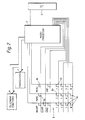
- Figure 2 is a schematic diagram of the keypad, microprocessor, and major functional elements of the telephone in Figure 1, and
- Figure 3 is a schematic diagram of the transmitter power amplifier stage of the telephone in Figure 1.
- The portable radio telephone shown in Figure 1 is a
cellular telephone 1 powered by a removablerechargeable battery pack 2. Thetelephone 1 includes a transceiver and all the other features conventionally found in a cellular telephone, as shown schematically in Figure 2. Amicroprocessor 4 is employed to control all the basic functions of the telephone and to control the keypad and display functions. Alternatively, however, the telephone functions may be controlled by a master microcomputer, while the keypad and display functions are under the control of a separate slave microcomputer coupled to communicate with the master microcomputer. - The user-interface of
telephone 1 comprises a display, e.g. aliquid crystal display 5, itself well-known in the art and akeypad 6 on the front of thetelephone 1. The display is coupled to and regulated by themicroprocessor 4 in the usual manner. Thekeypad 6 essentially comprises two main sets of keys, namely alpha-numeric keys 6a associated with alpha-numeric data especially for dialing telephone numbers, but also (optionally) for entering alphanumeric data into the telephone memories, e.g. a subscriber number index; and a set offunction keys 6b for enabling various predetermined functions or operations. - The
keys 6a are arranged in four rows of three keys each. As is conventional for the numeric key layout of a telephone, the top row comprises keys fornumbers numbers numbers - As is usual in cellular telephones, the
keys 6b include a "SEND" and "END" key for respectively initiating and terminating a telephone call. Another key, specifically located in the top left-hand corner is an "ON/OFF" key for turning the telephone on and off. Another of the function keys may be a menu or function key labeled, for example, "MENU" or "FUNCTION" or with a suitable abbreviation thereof. Depression of this key enables a variety of pre-set menus, the related instructions of which are stored in memory, to be viewed ondisplay 5 and selectively enabled. The various menus are selected by depressing the appropriate alphanumeric keys after depressing the "MENU" or "FUNCTION" key. The relevant menu is shown to the user in words or abbreviations on thedisplay panel 5. For example, the user may be able to select the ringing tone by appropriate menu selection. More sophisticated options may also be available via the menu facility. For example, the user may be able to enable the so-called Discontinuous Transmission mode which employs a voice activated switch which helps to reduce battery drain by transmitting only when speech is input to the microphone. - In accordance with the present invention a special menu facility is provided to permit manual selection of a battery save mode. Any predetermined sequence of keystrokes may be employed to select the respective menu which may display a legend such as "BATTERY SAVE ON" and "BATTERY SAVE OFF" on the
display panel 5. In a particular embodiment the following sequence of keystrokes were used to call up the battery save mode menu. Firstly the MENU key is depressed three times in succession in order to enter the third layer of menu functions, other menu functions being accessible via other menu layers. These other menus may be accessed by pressing the MENU key once for the first layer of menu functions, and twice for the second layer of menu functions. Next the user keys in a four digit personal identification number (PIN) followed by the digit "0". A message (e.g. BATTERY SAVE ON or BATTERY SAVE OFF) will now be shown on thedisplay 5 indicating whether or not the battery save mode is currently enabled. The alternative battery mode may be enabled simply by depressing another predetermined key of the alphanumerickey set 6a, specifically, for example the MENU key. The battery save mode can be toggled off and on by repeatedly depressing the MENU key. Suitably the menu mode may be exited by pressing the "END" key of function key set 6b. - The transmitter power control itself will now be described with reference to Figure 3 which shows the transmitter power amplifier stage of the portable cellular telephone in Figures 1 and 2. The transmitter power amplifier stage comprises a
power module 10 including a voltage controlledvariable gain amplifier 11. The power module used by the Applicant was a Motorola SHWE1084 available from Motorola Inc, Schaumburg, Illinois, USA. The power output ofmodule 10 is determined by the control voltage Vc applied to theamplifier 11. The output of the power module may be maintained at a uniform level by the use of a conventional level control circuit (not shown) in the form of a negative feedback loop. The control voltage Vc to be applied to theamplifier 11 is determined bymicroprocessor 4 in response to a request received from a base station to increase or decrease the output power of the transmitter. A set of values indicative respectively of the set of control voltages to be applied to theamplifier 11 are stored inEEPROM memory 12. The values stored in thememory 12 are used by themicroprocessor 4 to apply an appropriate signal to a digital-to-analogue converter (DAC) 13 which in turn applies the appropriate control voltage Vc to theamplifier 11 in accordance with the following table (Table 1), which shows the standard power levels for aclass 4 portable unit in the TACS and AMPS systems:
- Hence when the transmitter is operating at
power level 4, for example, the control voltage Vc applied toamplifier 11 is 1.52V and the output power is 100mW. If the base station requests an increase in power output the microprocessor responds by reading the adjacent appropriate power level value stored inEEPROM 12 and applying an appropriate signal toDAC 13. Accordingly theDAC 13 applies a control voltage of 1.97 volts to theamplifier 11 and the output power is increased to 251 mW. The transmitter is now operating at power level 3. If a request for a further power increase is made the transmitter would ordinarily step up topower level 0. (It is noted that in aclass 4portable unit levels DAC 13 is increased to 2.73V and the output power is accordingly increased to 600mW. - It can be seen from the table that the standard power levels specified in the TACS and AMPS systems are spaced apart by 4dB. Each level has a tolerance margin of +2dB/-4dB. Thus an actual power output falling within +2dB/-4dB of the nominal value will be regarded by the system as within tolerance and therefore transmitting at the requested level. The present invention exploits this by setting a
subsidiary power level 0 + between thestandard power level 0 and standard power level 3, as shown in the table. In an embodiment implemented by the Applicant thepower level 0+ was chosen to be 2dB belowstandard power level 0. The corresponding control voltage applied toamplifier 11 is 2.35 and the output power value is 400mW. Clearly the power saving betweenstandard power level 0 and thesubsidiary power level 0 + is 200mW which will save appreciable battery current and hence extend the call time with a given battery. Themicroprocessor 4 will always select fromEEPROM 12 the appropriate value to enable thesubsidiary power level 0 + in preference to thestandard power level 0 when the user has selected the battery save option in accordance with the procedure described above. On the other hand themicroprocessor 4 will select fromEEPROM 12 the appropriate value to enable thestandard power level 0 when the user has turned the battery save feature off in accordance with the procedure described above. Thus it will be seen that when the transmitter is operating at power level 3 and the base station requests an increase in output power from the telephone, the next power level which is enabled will depend on whether or not the battery save mode has been selected by the user. - In a modified embodiment the quality of the signal received by the portable telephone may be monitored and if the quality falls below a predetermined threshold while the transmitter is operating at the
subsidiary power level 0 the battery save mode is automatically disabled. The control voltage Vc applied to theamplifier 11 is therefore changed to 2.73V and the output power is consequently increased to the maximum level of 600mW. In one arrangement thestandard power level 0 will then remain permanently enabled (i.e. the battery save mode will remain disabled) until such time as the battery save mode is manually re-enabled by the user. Alternatively, assuming the battery save mode has been manually selected, the telephone will automatically revert back to transmitting at thesubsidiary power level 0 + when the received signal quality exceeds the threshold level. In other words, once the battery save mode has been manually selected, the output power at the maximum level may be switched automatically between thestandard power level 0 and thesubsidiary power level 0 + depending on the quality of the received signal. Suitably it may be the strength of the received signal which is monitored. The quality of the signal received by the telephone is assumed to correspond with the quality of the signal transmitted from the telephone and received by the base station. If the quality of the signal received by the telephone deteriorates it is likely that the quality of the signal transmitted by the telephone has similarly deteriorated when it is received by the base station. - In an alternative embodiment subsidiary power levels may also be provided at one or more of the lower power levels such that when the battery save mode is selected the respective subsidiary power level will be enabled in preference to the standard power level resulting in generally reduced power consumption and, therefore, extended battery life. However, it can be seen from the table that the power saving at lower levels is less significant because, in absolute values, the power levels become progressively closer together towards the lower levels. Moreover, there is a risk that if the power output at a lower level is reduced the base station will request the telephone to step up to the next power level and consequently the advantages of the subsidiary power level will be lost. At the
maximum power level 0, the transmitter cannot by definition step up to a higher level and therefore maximum advantage is likely to be achieved by implementing the subsidiary power level in associated with the maximum power level. - In view of the foregoing description it will be evident to a person skilled in the art that various modifications may be made within the scope of the present invention.
Claims (11)
wherein the output power selecting means determines for said at least one power level whether the first control signal or the second control signal is applied to the amplifying means.
Applications Claiming Priority (2)
| Application Number | Priority Date | Filing Date | Title |
|---|---|---|---|
| GB9116724A GB2258370B (en) | 1991-08-02 | 1991-08-02 | Cellular telephone |
| GB9116724 | 1991-08-02 |
Publications (3)
| Publication Number | Publication Date |
|---|---|
| EP0525962A2 true EP0525962A2 (en) | 1993-02-03 |
| EP0525962A3 EP0525962A3 (en) | 1993-06-30 |
| EP0525962B1 EP0525962B1 (en) | 1999-05-19 |
Family
ID=10699420
Family Applications (1)
| Application Number | Title | Priority Date | Filing Date |
|---|---|---|---|
| EP92305483A Expired - Lifetime EP0525962B1 (en) | 1991-08-02 | 1992-06-15 | Cellular telephone with transmitter power level control |
Country Status (4)
| Country | Link |
|---|---|
| EP (1) | EP0525962B1 (en) |
| JP (1) | JP3075848B2 (en) |
| DE (1) | DE69229201T2 (en) |
| GB (1) | GB2258370B (en) |
Cited By (9)
| Publication number | Priority date | Publication date | Assignee | Title |
|---|---|---|---|---|
| GB2298499A (en) * | 1995-02-28 | 1996-09-04 | Motorola Ltd | Method and apparatus for limiting peak current levels in electronic equipment |
| GB2308253A (en) * | 1995-12-15 | 1997-06-18 | Nec Corp | Reducing transmission power by data bit inversion |
| US6052581A (en) * | 1994-07-26 | 2000-04-18 | Nokia Mobile Phones Limited | Automatic NAM programming of radio telephone |
| WO2000064062A1 (en) * | 1999-04-16 | 2000-10-26 | Qualcomm Incorporated | System and method for selectively controlling amplifier performance |
| WO2000077950A1 (en) * | 1999-06-14 | 2000-12-21 | Qualcomm Incorporated | Adjusting maximum transmit power to maintain constant margin for adjacent channel power rejection |
| WO2002007494A2 (en) * | 2000-07-21 | 2002-01-31 | Sierra Wireless, Inc. | Personal computer card radio modem using non-standard power output level |
| FR2813487A1 (en) * | 2000-08-31 | 2002-03-01 | Cit Alcatel | METHOD AND DEVICE FOR CONTROLLING THE AMPLIFICATION OF THE SIGNAL TRANSMITTED BY A MOBILE TERMINAL FOR INCREASING THE AUTONOMY OF SAID MOBILE TERMINAL |
| EP1259087A1 (en) * | 2001-05-17 | 2002-11-20 | Sagem SA | Selection of transmitting power in a radiotelephone |
| US7876729B1 (en) | 1998-07-20 | 2011-01-25 | Qualcomm Incorporated | Intersystem base station handover |
Families Citing this family (4)
| Publication number | Priority date | Publication date | Assignee | Title |
|---|---|---|---|---|
| JP3105718B2 (en) * | 1993-11-19 | 2000-11-06 | 日本電気株式会社 | Individually selected paging receiver |
| JP3058269B2 (en) | 1998-04-08 | 2000-07-04 | 日本電気株式会社 | Mobile phone equipment |
| GB2343331B (en) * | 1998-10-27 | 2003-01-15 | Roke Manor Research | Improvements in or relating to mobile telecommunications systems |
| JP2002305475A (en) * | 2001-04-04 | 2002-10-18 | Kyocera Corp | Power-consumption state shifting method and mobile communication device |
Citations (7)
| Publication number | Priority date | Publication date | Assignee | Title |
|---|---|---|---|---|
| FR2614158A1 (en) * | 1987-04-16 | 1988-10-21 | Setsys | Radio telephone, especially portable |
| GB2213002A (en) * | 1987-11-27 | 1989-08-02 | Nec Corp | Rf power control circuit |
| EP0369135A2 (en) * | 1988-11-17 | 1990-05-23 | Motorola, Inc. | Power amplifier for a radio frequency signal |
| GB2229609A (en) * | 1989-02-15 | 1990-09-26 | Matsushita Electric Ind Co Ltd | Control of the output power of a mobile radio |
| EP0392079A2 (en) * | 1989-04-10 | 1990-10-17 | Mitsubishi Denki Kabushiki Kaisha | Radio transceiver |
| GB2233517A (en) * | 1989-06-26 | 1991-01-09 | Orbitel Mobile Communications | Transmitter power control with sideband reduction using memory |
| EP0416613A2 (en) * | 1989-09-06 | 1991-03-13 | Fujitsu Limited | Transmission power control circuit |
Family Cites Families (1)
| Publication number | Priority date | Publication date | Assignee | Title |
|---|---|---|---|---|
| US4636741A (en) * | 1985-11-01 | 1987-01-13 | Motorola, Inc. | Multi-level power amplifying circuitry for portable radio transceivers |
-
1991
- 1991-08-02 GB GB9116724A patent/GB2258370B/en not_active Expired - Fee Related
-
1992
- 1992-06-15 DE DE69229201T patent/DE69229201T2/en not_active Expired - Fee Related
- 1992-06-15 EP EP92305483A patent/EP0525962B1/en not_active Expired - Lifetime
- 1992-07-28 JP JP04201482A patent/JP3075848B2/en not_active Expired - Lifetime
Patent Citations (7)
| Publication number | Priority date | Publication date | Assignee | Title |
|---|---|---|---|---|
| FR2614158A1 (en) * | 1987-04-16 | 1988-10-21 | Setsys | Radio telephone, especially portable |
| GB2213002A (en) * | 1987-11-27 | 1989-08-02 | Nec Corp | Rf power control circuit |
| EP0369135A2 (en) * | 1988-11-17 | 1990-05-23 | Motorola, Inc. | Power amplifier for a radio frequency signal |
| GB2229609A (en) * | 1989-02-15 | 1990-09-26 | Matsushita Electric Ind Co Ltd | Control of the output power of a mobile radio |
| EP0392079A2 (en) * | 1989-04-10 | 1990-10-17 | Mitsubishi Denki Kabushiki Kaisha | Radio transceiver |
| GB2233517A (en) * | 1989-06-26 | 1991-01-09 | Orbitel Mobile Communications | Transmitter power control with sideband reduction using memory |
| EP0416613A2 (en) * | 1989-09-06 | 1991-03-13 | Fujitsu Limited | Transmission power control circuit |
Cited By (20)
| Publication number | Priority date | Publication date | Assignee | Title |
|---|---|---|---|---|
| US6052581A (en) * | 1994-07-26 | 2000-04-18 | Nokia Mobile Phones Limited | Automatic NAM programming of radio telephone |
| GB2298499A (en) * | 1995-02-28 | 1996-09-04 | Motorola Ltd | Method and apparatus for limiting peak current levels in electronic equipment |
| GB2298499B (en) * | 1995-02-28 | 1999-09-15 | Motorola Ltd | Method and apparatus for limiting peak current levels in electronic equipment |
| GB2308253A (en) * | 1995-12-15 | 1997-06-18 | Nec Corp | Reducing transmission power by data bit inversion |
| US5889604A (en) * | 1995-12-15 | 1999-03-30 | Nec Corporation | Method of and apparatus for data communications between portable information terminals |
| GB2308253B (en) * | 1995-12-15 | 2000-01-26 | Nec Corp | Method of carrying out data communication between portable information terminals |
| AU716569B2 (en) * | 1995-12-15 | 2000-03-02 | Nec Corporation | Method of and apparatus for data communications between portable information terminals |
| US7876729B1 (en) | 1998-07-20 | 2011-01-25 | Qualcomm Incorporated | Intersystem base station handover |
| WO2000064062A1 (en) * | 1999-04-16 | 2000-10-26 | Qualcomm Incorporated | System and method for selectively controlling amplifier performance |
| WO2000077950A1 (en) * | 1999-06-14 | 2000-12-21 | Qualcomm Incorporated | Adjusting maximum transmit power to maintain constant margin for adjacent channel power rejection |
| KR100722727B1 (en) * | 1999-06-14 | 2007-05-29 | 퀄컴 인코포레이티드 | Adjusting maximum transmit power to maintain constant margin for adjacent channel power rejection |
| US6785830B1 (en) | 2000-07-21 | 2004-08-31 | Sierra Wireless, Inc. | PC radio card capable of operating at a nonstandard power output level by limiting the current being drawn from a power amplifier |
| WO2002007494A3 (en) * | 2000-07-21 | 2002-08-01 | Sierra Wireless Inc | Personal computer card radio modem using non-standard power output level |
| WO2002007494A2 (en) * | 2000-07-21 | 2002-01-31 | Sierra Wireless, Inc. | Personal computer card radio modem using non-standard power output level |
| EP1184999A1 (en) * | 2000-08-31 | 2002-03-06 | Alcatel | Method and device for adjusting the amplification of a signal transmitted by a mobile terminal in order to increase battery life |
| FR2813487A1 (en) * | 2000-08-31 | 2002-03-01 | Cit Alcatel | METHOD AND DEVICE FOR CONTROLLING THE AMPLIFICATION OF THE SIGNAL TRANSMITTED BY A MOBILE TERMINAL FOR INCREASING THE AUTONOMY OF SAID MOBILE TERMINAL |
| US7593710B2 (en) | 2000-08-31 | 2009-09-22 | Ipg Electronics 504 Limited | Method and a device for controlling amplification of a signal emitted by a mobile terminal and increasing the autonomy of the mobile terminal |
| US8055236B2 (en) | 2000-08-31 | 2011-11-08 | Imerj, Ltd. | Devices for controlling amplification of a signal emitted by a mobile terminal and increasing the autonomy of the mobile terminal |
| EP1259087A1 (en) * | 2001-05-17 | 2002-11-20 | Sagem SA | Selection of transmitting power in a radiotelephone |
| FR2824972A1 (en) * | 2001-05-17 | 2002-11-22 | Sagem | TRANSMISSION POWER SELECTION IN A RADIOTELEPHONE |
Also Published As
| Publication number | Publication date |
|---|---|
| DE69229201D1 (en) | 1999-06-24 |
| EP0525962A3 (en) | 1993-06-30 |
| DE69229201T2 (en) | 1999-12-23 |
| GB2258370A (en) | 1993-02-03 |
| EP0525962B1 (en) | 1999-05-19 |
| JPH05227081A (en) | 1993-09-03 |
| GB9116724D0 (en) | 1991-09-18 |
| JP3075848B2 (en) | 2000-08-14 |
| GB2258370B (en) | 1995-09-06 |
Similar Documents
| Publication | Publication Date | Title |
|---|---|---|
| EP0525962B1 (en) | Cellular telephone with transmitter power level control | |
| US5036532A (en) | Portable telephone with power source/mode change during calls | |
| US6895220B2 (en) | Mobile communication device capable of carrying out both indirect and direct communication | |
| CN1074884C (en) | Method of operating a combination radiotelephone and paging device | |
| US7366131B2 (en) | Power saving method in a mobile communication terminal | |
| US5999832A (en) | Method of and apparatus for controlling a transmit power of a communication device | |
| US6731957B1 (en) | Wireless communication device capable of saving battery power by switching communication mode | |
| US7653419B2 (en) | Mobile phone with power saving function | |
| CN1103516C (en) | Radio communication equipment having selective functions of utilizing analog mode and digital mode | |
| US8698620B2 (en) | Wireless communications device | |
| CA2037050C (en) | Portable telephone with power source/mode change during calls | |
| CN1980482B (en) | Cordless communication apparatus | |
| US6009309A (en) | Method of operation a combination radiotelephone and paging device and method of operation | |
| US6205331B1 (en) | Memory sharing method for integrated digital cordless telephone and radio paging receiver | |
| US20010053702A1 (en) | Mobile radio communication apparatus having a plurality of mins | |
| GB2350022A (en) | User-controlled reception restriction in a radio communication unit | |
| JP2938017B1 (en) | Mobile radio terminal and alarm output method in mobile radio terminal | |
| KR100262653B1 (en) | Method of controlling power supplied to backlight device in cdma type terminal equipment | |
| KR20070078441A (en) | Method for setting emergency battery mode of mobile phone | |
| EP1204261B1 (en) | Wireless communication device with selective power supply function | |
| JP4229539B2 (en) | Mobile radio terminal | |
| KR20030051008A (en) | Setting method of urgent call when the mobile phone's battery is exhausted | |
| JPH0591041A (en) | Portable telephone set | |
| KR100251562B1 (en) | Apparatus and method for power saving of wireless phone | |
| KR20010046664A (en) | Power control apparatus and method for emergency call |
Legal Events
| Date | Code | Title | Description |
|---|---|---|---|
| PUAI | Public reference made under article 153(3) epc to a published international application that has entered the european phase |
Free format text: ORIGINAL CODE: 0009012 |
|
| AK | Designated contracting states |
Kind code of ref document: A2 Designated state(s): DE FR GB IT SE |
|
| PUAL | Search report despatched |
Free format text: ORIGINAL CODE: 0009013 |
|
| RAP1 | Party data changed (applicant data changed or rights of an application transferred) |
Owner name: NOKIA MOBILE PHONES (U.K.) LIMITED |
|
| RHK1 | Main classification (correction) |
Ipc: H04B 7/005 |
|
| AK | Designated contracting states |
Kind code of ref document: A3 Designated state(s): DE FR GB IT SE |
|
| 17P | Request for examination filed |
Effective date: 19930807 |
|
| 17Q | First examination report despatched |
Effective date: 19951227 |
|
| GRAG | Despatch of communication of intention to grant |
Free format text: ORIGINAL CODE: EPIDOS AGRA |
|
| GRAG | Despatch of communication of intention to grant |
Free format text: ORIGINAL CODE: EPIDOS AGRA |
|
| GRAH | Despatch of communication of intention to grant a patent |
Free format text: ORIGINAL CODE: EPIDOS IGRA |
|
| GRAH | Despatch of communication of intention to grant a patent |
Free format text: ORIGINAL CODE: EPIDOS IGRA |
|
| GRAA | (expected) grant |
Free format text: ORIGINAL CODE: 0009210 |
|
| AK | Designated contracting states |
Kind code of ref document: B1 Designated state(s): DE FR GB IT SE |
|
| REF | Corresponds to: |
Ref document number: 69229201 Country of ref document: DE Date of ref document: 19990624 |
|
| ET | Fr: translation filed | ||
| ITF | It: translation for a ep patent filed |
Owner name: MODIANO & ASSOCIATI S.R.L. |
|
| PLBE | No opposition filed within time limit |
Free format text: ORIGINAL CODE: 0009261 |
|
| STAA | Information on the status of an ep patent application or granted ep patent |
Free format text: STATUS: NO OPPOSITION FILED WITHIN TIME LIMIT |
|
| 26N | No opposition filed | ||
| REG | Reference to a national code |
Ref country code: GB Ref legal event code: IF02 |
|
| PGFP | Annual fee paid to national office [announced via postgrant information from national office to epo] |
Ref country code: FR Payment date: 20020610 Year of fee payment: 11 |
|
| PGFP | Annual fee paid to national office [announced via postgrant information from national office to epo] |
Ref country code: SE Payment date: 20020611 Year of fee payment: 11 |
|
| PGFP | Annual fee paid to national office [announced via postgrant information from national office to epo] |
Ref country code: GB Payment date: 20020612 Year of fee payment: 11 |
|
| PGFP | Annual fee paid to national office [announced via postgrant information from national office to epo] |
Ref country code: DE Payment date: 20020619 Year of fee payment: 11 |
|
| PG25 | Lapsed in a contracting state [announced via postgrant information from national office to epo] |
Ref country code: GB Free format text: LAPSE BECAUSE OF NON-PAYMENT OF DUE FEES Effective date: 20030615 |
|
| PG25 | Lapsed in a contracting state [announced via postgrant information from national office to epo] |
Ref country code: SE Free format text: LAPSE BECAUSE OF NON-PAYMENT OF DUE FEES Effective date: 20030616 |
|
| PG25 | Lapsed in a contracting state [announced via postgrant information from national office to epo] |
Ref country code: DE Free format text: LAPSE BECAUSE OF NON-PAYMENT OF DUE FEES Effective date: 20040101 |
|
| EUG | Se: european patent has lapsed | ||
| GBPC | Gb: european patent ceased through non-payment of renewal fee |
Effective date: 20030615 |
|
| PG25 | Lapsed in a contracting state [announced via postgrant information from national office to epo] |
Ref country code: FR Free format text: LAPSE BECAUSE OF NON-PAYMENT OF DUE FEES Effective date: 20040227 |
|
| REG | Reference to a national code |
Ref country code: FR Ref legal event code: ST |
|
| PG25 | Lapsed in a contracting state [announced via postgrant information from national office to epo] |
Ref country code: IT Free format text: LAPSE BECAUSE OF NON-PAYMENT OF DUE FEES Effective date: 20050615 |