EP0522922A1 - Method and apparatus for ultrasonic examination of the condition of a bore surface - Google Patents
Method and apparatus for ultrasonic examination of the condition of a bore surface Download PDFInfo
- Publication number
- EP0522922A1 EP0522922A1 EP92401844A EP92401844A EP0522922A1 EP 0522922 A1 EP0522922 A1 EP 0522922A1 EP 92401844 A EP92401844 A EP 92401844A EP 92401844 A EP92401844 A EP 92401844A EP 0522922 A1 EP0522922 A1 EP 0522922A1
- Authority
- EP
- European Patent Office
- Prior art keywords
- bore
- support
- checked
- amplitude
- sole
- Prior art date
- Legal status (The legal status is an assumption and is not a legal conclusion. Google has not performed a legal analysis and makes no representation as to the accuracy of the status listed.)
- Granted
Links
Images

Classifications
-
- G—PHYSICS
- G01—MEASURING; TESTING
- G01N—INVESTIGATING OR ANALYSING MATERIALS BY DETERMINING THEIR CHEMICAL OR PHYSICAL PROPERTIES
- G01N29/00—Investigating or analysing materials by the use of ultrasonic, sonic or infrasonic waves; Visualisation of the interior of objects by transmitting ultrasonic or sonic waves through the object
- G01N29/04—Analysing solids
- G01N29/11—Analysing solids by measuring attenuation of acoustic waves
-
- G—PHYSICS
- G01—MEASURING; TESTING
- G01N—INVESTIGATING OR ANALYSING MATERIALS BY DETERMINING THEIR CHEMICAL OR PHYSICAL PROPERTIES
- G01N29/00—Investigating or analysing materials by the use of ultrasonic, sonic or infrasonic waves; Visualisation of the interior of objects by transmitting ultrasonic or sonic waves through the object
- G01N29/04—Analysing solids
- G01N29/041—Analysing solids on the surface of the material, e.g. using Lamb, Rayleigh or shear waves
-
- G—PHYSICS
- G01—MEASURING; TESTING
- G01N—INVESTIGATING OR ANALYSING MATERIALS BY DETERMINING THEIR CHEMICAL OR PHYSICAL PROPERTIES
- G01N29/00—Investigating or analysing materials by the use of ultrasonic, sonic or infrasonic waves; Visualisation of the interior of objects by transmitting ultrasonic or sonic waves through the object
- G01N29/22—Details, e.g. general constructional or apparatus details
- G01N29/30—Arrangements for calibrating or comparing, e.g. with standard objects
-
- G—PHYSICS
- G01—MEASURING; TESTING
- G01N—INVESTIGATING OR ANALYSING MATERIALS BY DETERMINING THEIR CHEMICAL OR PHYSICAL PROPERTIES
- G01N29/00—Investigating or analysing materials by the use of ultrasonic, sonic or infrasonic waves; Visualisation of the interior of objects by transmitting ultrasonic or sonic waves through the object
- G01N29/34—Generating the ultrasonic, sonic or infrasonic waves, e.g. electronic circuits specially adapted therefor
- G01N29/348—Generating the ultrasonic, sonic or infrasonic waves, e.g. electronic circuits specially adapted therefor with frequency characteristics, e.g. single frequency signals, chirp signals
-
- G—PHYSICS
- G01—MEASURING; TESTING
- G01N—INVESTIGATING OR ANALYSING MATERIALS BY DETERMINING THEIR CHEMICAL OR PHYSICAL PROPERTIES
- G01N2291/00—Indexing codes associated with group G01N29/00
- G01N2291/01—Indexing codes associated with the measuring variable
- G01N2291/015—Attenuation, scattering
-
- G—PHYSICS
- G01—MEASURING; TESTING
- G01N—INVESTIGATING OR ANALYSING MATERIALS BY DETERMINING THEIR CHEMICAL OR PHYSICAL PROPERTIES
- G01N2291/00—Indexing codes associated with group G01N29/00
- G01N2291/04—Wave modes and trajectories
- G01N2291/042—Wave modes
- G01N2291/0422—Shear waves, transverse waves, horizontally polarised waves
-
- G—PHYSICS
- G01—MEASURING; TESTING
- G01N—INVESTIGATING OR ANALYSING MATERIALS BY DETERMINING THEIR CHEMICAL OR PHYSICAL PROPERTIES
- G01N2291/00—Indexing codes associated with group G01N29/00
- G01N2291/04—Wave modes and trajectories
- G01N2291/044—Internal reflections (echoes), e.g. on walls or defects
-
- G—PHYSICS
- G01—MEASURING; TESTING
- G01N—INVESTIGATING OR ANALYSING MATERIALS BY DETERMINING THEIR CHEMICAL OR PHYSICAL PROPERTIES
- G01N2291/00—Indexing codes associated with group G01N29/00
- G01N2291/10—Number of transducers
- G01N2291/101—Number of transducers one transducer
-
- G—PHYSICS
- G01—MEASURING; TESTING
- G01N—INVESTIGATING OR ANALYSING MATERIALS BY DETERMINING THEIR CHEMICAL OR PHYSICAL PROPERTIES
- G01N2291/00—Indexing codes associated with group G01N29/00
- G01N2291/26—Scanned objects
- G01N2291/263—Surfaces
- G01N2291/2634—Surfaces cylindrical from outside
-
- G—PHYSICS
- G01—MEASURING; TESTING
- G01N—INVESTIGATING OR ANALYSING MATERIALS BY DETERMINING THEIR CHEMICAL OR PHYSICAL PROPERTIES
- G01N2291/00—Indexing codes associated with group G01N29/00
- G01N2291/26—Scanned objects
- G01N2291/263—Surfaces
- G01N2291/2636—Surfaces cylindrical from inside
-
- G—PHYSICS
- G01—MEASURING; TESTING
- G01N—INVESTIGATING OR ANALYSING MATERIALS BY DETERMINING THEIR CHEMICAL OR PHYSICAL PROPERTIES
- G01N2291/00—Indexing codes associated with group G01N29/00
- G01N2291/26—Scanned objects
- G01N2291/263—Surfaces
- G01N2291/2638—Complex surfaces
Landscapes
- Physics & Mathematics (AREA)
- Biochemistry (AREA)
- General Physics & Mathematics (AREA)
- Life Sciences & Earth Sciences (AREA)
- Chemical & Material Sciences (AREA)
- Analytical Chemistry (AREA)
- Pathology (AREA)
- General Health & Medical Sciences (AREA)
- Health & Medical Sciences (AREA)
- Immunology (AREA)
- Acoustics & Sound (AREA)
- Investigating Or Analyzing Materials By The Use Of Ultrasonic Waves (AREA)
- Analysing Materials By The Use Of Radiation (AREA)
- Pressure Welding/Diffusion-Bonding (AREA)
- Length Measuring Devices Characterised By Use Of Acoustic Means (AREA)
Abstract
Description
La présente invention est relative à un procédé et un dispositif de contrôle par ultrasons de l'état de surface d'un alésage, notamment de l'alésage d'un essieu-axe de chemin de fer.The present invention relates to a method and a device for ultrasonic control of the surface condition of a bore, in particular of the bore of a railway axle-axle.
Les essieux-axes de chemin de fer sont des pièces longues de révolution dans lesquelles est usiné sur toute leur longueur par forage, un alésage axial. On contrôle la surface de l'alésage afin de vérifier qu'elle ne comporte aucun défaut tel qu'un coup d'outil, risquant de diminuer la résistance à la fatigue de l'essieu-axe. Il a été à cet effet proposé d'exécuter des mesures de rugosité. Mais ces mesures ne peuvent être effectuées qu'à proximité des extrémités de l'essieu-axe. Il est également connu d'exécuter un contrôle par ultrasons à partir de l'extérieur de l'essieu-axe. Mais cette méthode ne permet pas de contrôler la totalité de l'alésage. En effet l'essieu-axe comporte plusieurs parties cylindriques reliées par des congés de raccordement. Dans les zones situées à proximité de ces congés de raccordement, il n'est pas possible d'exécuter un contrôle par ultrasons à partir de l'extérieur. En outre, cette méthode est longue car il est nécessaire de balayer toute la surface de l'essieu-axe.The railway axle-axles are long parts of revolution in which an axial bore is machined over their entire length by drilling. The surface of the bore is checked in order to verify that it does not have any defect such as a tool stroke, risking reducing the fatigue strength of the axle-axle. To this end, it has been proposed to carry out roughness measurements. However, these measurements can only be made near the ends of the axle. It is also known to perform ultrasonic testing from outside the axle. However, this method does not control the entire bore. Indeed the axle-axis comprises several cylindrical parts connected by connecting leaves. In the areas near these connection leaves, it is not possible to perform an ultrasonic test from the outside. In addition, this method is long because it is necessary to sweep the entire surface of the axle.
L'invention a donc pour but de réaliser un procédé et un dispositif qui permettent de contrôler l'intégralité de la surface d'un alésage de façon simple et rapide.The object of the invention is therefore to provide a method and a device which make it possible to control the entire surface of a bore in a simple and rapid manner.
Le procédé de contrôle visé par l'invention est caractérisé par les opérations suivantes :
- à l'aide d'un émetteur d'ondes ultrasonores longitudinales orienté convenablement, de fréquence adaptée et coopérant avec les surfaces de l'alésage, on génère sur cette surface une onde transversale de surface,
- on compare l'amplitude des échos obtenus aux valeurs d'une courbe d'étalonnage tracée à partir d'un alésage muni d'un défaut-étalon et identique à l'alésage à contrôler,
- et lorsque l'amplitude d'un écho est supérieure à une fraction déterminée de la valeur indiquée par la courbe d'étalonnage, on considère qu'il y a un défaut.
- using a suitably oriented longitudinal ultrasonic wave transmitter of suitable frequency and cooperating with the surfaces of the bore, a surface transverse wave is generated on this surface,
- the amplitude of the echoes obtained is compared with the values of a calibration curve drawn from a bore provided with a standard fault and identical to the bore to be checked,
- and when the amplitude of an echo is greater than a determined fraction of the value indicated by the calibration curve, it is considered that there is a defect.
Le dispositif pour la mise en oeuvre de ce procédé comprend un bloc palpeur pourvu d'une sonde émettrice-réceptrice orientable, et un support dans lequel est ménagé un logement adapté pour recevoir le bloc palpeur, lequel ainsi que son support présentent une surface conjuguée de la surface interne de l'alésage à contrôler afin de pouvoir coopérer avec celle-ci.The device for implementing this method comprises a feeler block provided with an adjustable emitter-receiver probe, and a support in which is provided a housing adapted to receive the feeler block, which as well as its support have a mating surface of the internal surface of the bore to be checked in order to be able to cooperate with it.
Suivant un mode de réalisation de ce dispositif, le support comporte une partie montée coulissante sur des tiges de liaison avec une semelle, ces tiges étant pourvues de moyens élastiques tendant à écarter ladite partie et la semelle l'une de l'autre, le logement du bloc palpeur étant ménagé dans ladite partie, sur laquelle est agencée la surface conjuguée avec la surface intérieure de l'alésage.According to one embodiment of this device, the support comprises a part slidably mounted on rods connecting with a sole, these rods being provided with elastic means tending to separate said part and the sole from each other, the housing of the feeler block being formed in said part, on which is arranged the surface conjugated with the internal surface of the bore.
Ainsi pour introduire ce bloc palpeur à l'intérieur de l'alésage à contrôler, on rapproche l'une de l'autre les deux parties constitutives du support à l'encontre de la force de rappel des moyens élastiques, qui ensuite écarte l'une de l'autre la semelle et la partie coulissant sur les tiges de liaison, en appliquant ces deux pièces contre la surface interne de l'alésage.Thus, to introduce this feeler block inside the bore to be checked, the two constituent parts of the support are brought closer to each other against the restoring force of the elastic means, which then spreads the one of the other the sole and the sliding part on the connecting rods, applying these two parts against the internal surface of the bore.
D'autres particularités et avantages de l'invention apparaîtront au cours de la description qui va suivre, faite en référence aux dessins annexés qui en illustrent une forme de réalisation à titre d'exemple non limitatif.Other features and advantages of the invention will become apparent during the description which follows, given with reference to the accompanying drawings which illustrate an embodiment by way of nonlimiting example.
La figure 1 est une vue en coupe longitudinale axiale d'un essieu-axe de chemin de fer dans l'alésage duquel est placé un dispositif de contrôle conforme à l'invention.Figure 1 is a view in axial longitudinal section of a railway axle-axle in the bore of which is placed a control device according to the invention.
La figure 2 est une vue en coupe longitudinale axiale d'un essieu-axe de référence servant à tracer une courbe d'étalonnage du dispositif de contrôle.FIG. 2 is a view in axial longitudinal section of a reference axle-axis used to draw a calibration curve of the control device.
La figure 3 est un exemple de courbes d'étalonnage du dispositif de contrôle selon l'invention.FIG. 3 is an example of calibration curves of the control device according to the invention.
La figure 4 est une vue en perspective à grandeur réelle d'un mode de réalisation du dispositif de contrôle par ultrasons selon l'invention.Figure 4 is a full-scale perspective view of an embodiment of the ultrasonic testing device according to the invention.
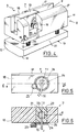
La figure 5 est une vue en élévation longitudinale à échelle agrandie du bloc palpeur de la Fig.4.Figure 5 is a longitudinal elevational view on an enlarged scale of the probe block of Fig.4.
La figure 6 est une vue en coupe axiale du bloc palpeur suivant 6/6 de la Fig.5.Figure 6 is an axial sectional view of the probe block along 6/6 of Fig.5.
On décrira tout d'abord en référence aux Fig.1 à 3 le procédé de contrôle visé par l'invention.Firstly, with reference to FIGS. 1 to 3, the control process targeted by the invention will be described.
Un essieu-axe 1 de chemin de fer présente un alésage axial 2 foré, dont on veut contrôler l'état de surface. Pour ce faire, on introduit dans l'alésage 2, à l'une de ses extrémités, un dispositif 3 pouvant émettre et recevoir des ultrasons. Le dispositif 3 est relié à des moyens connus et non représentés de génération d'impulsions, de réception et de visualisation de signaux. En orientant convenablement l'angle d'incidence des ultrasons émis par rapport à la surface 2, on fait disparaître les ondes longitudinales pouvant se propager dans l'essieu-axe 1, et il ne reste qu'une onde de surface 27, dite onde de Rayleigh, qui se propage à la surface de l'alésage 2, cette onde 27 étant représentée symboliquement par une ligne ondulée à la Fig.1.A
Si une telle onde 27 rencontre un défaut 4 suffisamment important, elle se réfléchit partiellement sur ce défaut. L'onde réfléchie revient jusqu'au dispositif 3 où elle est détectée de façon connue en soi. Cette détection est visualisée par un moyen de visualisation qui, de façon également connue en soi, permet de déterminer l'amplitude de l'écho et la position du défaut 4 sur une génératrice de la surface de l'alésage 2. En faisant tourner le dispositif 3 autour de l'axe XX de l'alésage 2, on peut contrôler ainsi la surface de l'alésage au moins jusqu'à mi-longueur, et ce sans déplacer le dispositif 3 longitudinalement tout le long de l'alésage 2. En plaçant ensuite le dispositif 3 à l'autre extrémité de l'essieu-axe 1, il est possible de contrôler la seconde moitié de l'alésage 2, et par conséquent la totalité de la surface de l'alésage 2 en deux opérations.If such a
Pour exécuter ce contrôle, il faut au préalable régler et étalonner le dispositif 3. A cet effet on utilise un essieu-axe 1A de même géométrie, de même composition chimique et ayant subi le même traitement thermique que les essieux-axes à contrôler (Fig.2). On ouvre partiellement l'essieu-axe 1A, et on crée à la surface de l'alésage 2A un défaut-étalon 5 situé à peu près à mi-distance des deux extrémités de l'essieu-axe 1A.To carry out this control, the
Le défaut-étalon 5 peut, de préférence, être une entaille à bords parallèles et à fond plat, ayant par exemple une largeur de 1mm et une profondeur de 1mm. Le défaut-étalon 5 peut également être une entaille en V avec par exemple un angle au sommet de 60° et une profondeur de 0,3mm.The
Le défaut-étalon 5 est réalisé après une préparation de la surface de l'alésage 2A par des moyens connus, la surface obtenue ayant une rugosité caractérisée par un coefficient Ra déterminé, par exemple Ra inférieur ou égal à 3,2 (Ra étant le coefficient de rugosité moyenne arithmétique).The
Le dispositif 3 émet un faisceau d'ultrasons 6 formant avec la normale à la surface de l'alésage 2A un angle d'incidence I. Le réglage de cet angle d'incidence I s'exécute en positionnant le dispositif 3 sur la surface de l'alésage 2A le long de la génératrice passant par le défaut-étalon 5. Le dispositif 3 émet alors des impulsions ultrasonores et on règle l'orientation de l'émetteur d'ultrasons de telle sorte que l'amplitude de l'écho renvoyé par le défaut-étalon 5 soit maximale. Une fois le réglage d'angle d'incidence réalisé, on procède à l'étalonnage du dispositif 3 en déplaçant celui-ci le long de la génératrice et en enregistrant l'amplitude de l'écho renvoyé par le défaut-étalon 5, en fonction de la distance d entre ce dernier et le dispositif 3. On établit ainsi des courbes d'étalonnage telles que les courbes C1 et C2 de la Fig.3, sur laquelle les ordonnées h représentent l'amplitude de l'écho en fonction de la distance d.The
Lors du contrôle d'un alésage 2, on mesure l'amplitude des échos et la distance d entre le dispositif 3 et le défaut détecté, et on compare cette amplitude à celle fournie par la courbe d'étalonnage C. Si l'amplitude mesurée est par exemple la moitié de celle indiquée par la courbe, on peut considérer qu'il n'y a pas de défaut ou que le défaut est acceptable. Dans le cas contraire, on exécute un examen minutieux au voisinage du défaut détecté.When checking a
A titre d'exemple numérique indicatif non limitatif, pour un essieu-axe 1 en acier, la fréquence de l'onde ultrasonique longitudinale 27 la mieux adaptée est 2MHz, et l'angle d'incidence I optimal est voisin de 82°.By way of nonlimiting indicative numerical example, for a
Un mode de réalisation du dispositif 3 de mise en oeuvre du procédé qui vient d'être décrit est représenté aux Fig.4 à 6.An embodiment of the
Ce dispositif 3 comprend un bloc palpeur 7 émetteur-récepteur d'ultrasons et un support 8 dans lequel est ménagé un logement 9 adapté pour recevoir le bloc palpeur 7. Le support 8 comporte une partie 11 montée coulissante sur des tiges 12 de liaison avec une semelle 13, ces tiges 12 étant par exemple au nombre de 4 comme représenté. Elles peuvent être fixées à la semelle 13 et coulisser dans des trous correspondants (non visibles aux dessins) ménagés intérieurement à la partie 11, ou inversement les tiges 12 peuvent être fixées à la partie 11 et coulisser dans des trous complémentaires formés dans la semelle 11.This
Des moyens élastiques constitués par exemple par des ressorts hélicoïdaux 14 coaxiaux aux tiges 12, comprimés entre la semelle 13 et la partie 11, tendent à écarter ces deux pièces l'une de l'autre.Elastic means constituted for example by
Dans l'exemple décrit, la partie 11 et la semelle 13 ont une forme allongée, approximativement parallélépipédique. Le logement 9 s'étend longitudinalement d'une extrémité à l'autre de la partie coulissante 11 (en supposant que les tiges 12 sont fixées à la semelle 13 et que la partie 11 coulisse donc sur les tiges 12). Le logement 9 forme donc une saignée longitudinale dans la partie coulissante 11 et est avantageusement complété par deux dégagements latéraux formés dans la partie 11 de chaque côté de la saignée 9 pour permettre la mise en place du bloc palpeur 7. En effet ce dernier est relié aux moyens (non représentés) de génération d'impulsions, de détection et de visualisation, par un cordon 16 qui traverse l'un des dégagements 15.In the example described, the
De part et d'autre du logement longitudinal 9, la surface de la partie 11, opposée à la semelle 13, est conjuguée de la surface cylindrique interne de l'alésage 2 à contrôler, afin de pouvoir coopérer avec celle-ci. Les deux surfaces 17, symétriques l'une de l'autre par rapport au logement longitudinal 9, sont donc des portions de cylindre ayant le même rayon de courbure que l'alésage 2.On either side of the
La face de la semelle 13 opposée aux surfaces cylindriques 17 et 19 présente également des congés cylindriques 10 de raccordement avec ses faces latérales planes 20; les congés 10 constituent donc des portions de surfaces cylindriques de même rayon de courbure que l'alésage 2 et que les surfaces opposées 17, 19, afin de pouvoir s'appliquer comme celle-ci à la surface de l'alésage 2.The face of the sole 13 opposite the
Le bloc palpeur 7 comporte (Fig.5 et 6) une première pièce 18 dont une surface latérale 19 est profilée de manière à être complémentaire des surfaces 17 du support 8. En d'autres termes, la hauteur de la pièce 18 étant égale à la profondeur du logement 9, et la surface latérale 19 ayant le même rayon de courbure que les surfaces 17, affleure celles-ci, de telle sorte que les surfaces 17 et 19 puissent s'appliquer sur la surface cylindrique de l'alésage 2 à contrôler.The
Le bloc palpeur 7 comprend une seconde pièce 21, cylindrique, montée rotative autour d'un axe YY dans un trou cylindrique 22 formé dans la première pièce 18, et un émetteur-récepteur d'ultrasons 23 est noyé à l'intérieur de la pièce 21, cette sonde 23 étant reliée au cordon 16. La pièce 21 est réalisée en une matière synthétique appropriée, de façon connue. L'axe de rotation YY de la pièce cylindrique 21 est perpendiculaire à l'axe longitudinal du logement 9 et par conséquent à l'axe XX de l'alésage 2 à contrôler.The
Le bloc palpeur 7 est équipé de moyens de réglage de la position angulaire de la pièce cylindrique 21 autour de son axe de rotation YY, qui dans l'exemple représenté sont constitués de la manière suivante : un engrenage 24 est fixé à l'une des faces frontales de la pièce cylindrique 21, coaxialement à l'axe YY et est percé en son centre d'un trou de passage du cordon 16. Un bouton moleté 25 est monté sur la face latérale de la pièce 18 et positionné de manière à pouvoir coopérer avec la denture de l'engrenage 24, dont la position angulaire peut être repérée par tout moyen approprié, par exemple un vernier 26 monté sur la pièce 18. Ainsi la rotation du bouton moleté 25 de commande entraîne l'engrenage 24 et la pièce cylindrique 21 autour de l'axe YY, ce qui permet d'orienter le faisceau ultrasonique 6 dans la direction voulue, à l'intérieur du logement 9 et de l'alésage 2. La rotation du cylindre 21 permet de régler l'angle d'incidence I des ultrasons 6, la position optimale de l'émetteur-récepteur 23 étant repérée à l'aide du vernier 26.The
La mise en oeuvre du dispositif de contrôle 3 qui vient d'être décrit s'effectue de la manière suivante.The implementation of the
Avant de contrôler un alésage 2 l'opérateur installe le dispositif dans l'alésage 2A d'un essieu étalon 1A, puis l'opérateur oriente la sonde émettrice-réceptrice 23 autour de son axe de rotation YY en agissant sur le bouton de commande 25, comme expliqué ci-dessus. Cette manoeuvre permet de régler l'angle d'incidence I du faisceau ultrasonique 6, générant à la surface de l'alésage 2A l'onde transversale de surface 27.Before checking a
Après avoir réglé l'orientation de la sonde émettrice-réceptrice, l'opérateur trace la courbe d'étalonnage comme indiqué ci-dessus.After adjusting the orientation of the probe transmitter-receiver, the operator draws the calibration curve as indicated above.
Pour contrôler un alésage 2, tout d'abord, par pression sur la semelle 13 et sur la partie 11, l'opérateur rapproche ces deux éléments, afin de pouvoir introduire l'ensemble du dispositif 3 à l'intérieur de l'alésage 2 à contrôler.To control a
Dès que la pression exercée sur la semelle 13 et la partie 11 à l'encontre de la force de rappel des ressorts 14 est relâchée, ces derniers écartent les deux pièces l'une de l'autre et appliquent fermement les surfaces 17, 19 et 10 contre la surface de l'alésage 2, le dispositif 3 étant ainsi fixé en position dans l'alésage à contrôler.As soon as the pressure exerted on the sole 13 and the
Si un défaut tel que 4 existe dans la surface contrôlée, l'amplitude des échos obtenus est comparée aux valeurs de référence de la courbe d'étalonnage C, comme expliqué ci-dessus dans le cadre du procédé conforme à l'invention.If a defect such as 4 exists in the controlled surface, the amplitude of the echoes obtained is compared with the reference values of the calibration curve C, as explained above in the context of the method according to the invention.
A titre numérique indicatif, la sonde émettrice-réceptrice 23 peut avoir un diamètre de 10mm.By way of numerical indication, the transmitter-
Claims (8)
Applications Claiming Priority (2)
| Application Number | Priority Date | Filing Date | Title |
|---|---|---|---|
| FR9108094 | 1991-06-28 | ||
| FR919108094A FR2678385B1 (en) | 1991-06-28 | 1991-06-28 | METHOD AND DEVICE FOR ULTRASONIC CONTROL OF THE SURFACE CONDITION OF A BORE, ESPECIALLY THE BORE OF A RAILWAY AXLE. |
Publications (2)
| Publication Number | Publication Date |
|---|---|
| EP0522922A1 true EP0522922A1 (en) | 1993-01-13 |
| EP0522922B1 EP0522922B1 (en) | 1996-10-16 |
Family
ID=9414482
Family Applications (1)
| Application Number | Title | Priority Date | Filing Date |
|---|---|---|---|
| EP92401844A Expired - Lifetime EP0522922B1 (en) | 1991-06-28 | 1992-06-29 | Method and apparatus for ultrasonic examination of the condition of a bore surface |
Country Status (6)
| Country | Link |
|---|---|
| US (1) | US5503019A (en) |
| EP (1) | EP0522922B1 (en) |
| AT (1) | ATE144325T1 (en) |
| DE (1) | DE69214539T2 (en) |
| ES (1) | ES2095427T3 (en) |
| FR (1) | FR2678385B1 (en) |
Cited By (4)
| Publication number | Priority date | Publication date | Assignee | Title |
|---|---|---|---|---|
| DE4330909C1 (en) * | 1993-09-11 | 1994-10-20 | Bbc Reaktor Gmbh | Eddy-current testing probe for insertion into a gap |
| WO2006059912A1 (en) * | 2004-12-02 | 2006-06-08 | Purepine Mouldings Limited | A weatherboard system and related means of/or providing a weatherboard assembly |
| FR2917833A1 (en) * | 2007-06-21 | 2008-12-26 | V & M France Soc Par Actions S | METHOD AND APPARATUS FOR MANUAL NON-DESTRUCTIVE CONTROL OF TUBULAR AXIS AXES WITH INTERNAL AND EXTERNAL VARIABLE RAY PROFILES |
| JP2010530528A (en) * | 2007-06-21 | 2010-09-09 | ヴイ・アンド・エム・フランス | Automatic nondestructive inspection method and apparatus for tubular axles with varying inner and outer diameter shapes |
Families Citing this family (8)
| Publication number | Priority date | Publication date | Assignee | Title |
|---|---|---|---|---|
| FR2847344B1 (en) * | 2002-11-20 | 2005-02-25 | Framatome Anp | PROBE FOR CONTROLLING AN INTERNAL WALL OF A CONDUIT |
| WO2006099397A2 (en) * | 2005-03-14 | 2006-09-21 | Transportation Technology Center, Inc. | System for non-contact interrogation of railroad axles using laser-based ultrasonic inspection |
| US7669477B2 (en) * | 2006-12-22 | 2010-03-02 | The Boeing Company | Ultrasonic probe for hollow fuse pin inspection |
| US8711222B2 (en) * | 2011-04-27 | 2014-04-29 | Georgetown Rail Equipment Company | Method and system for calibrating laser profiling systems |
| DE102011051759A1 (en) * | 2011-07-12 | 2013-01-17 | BAM Bundesanstalt für Materialforschung und -prüfung | Method for monitoring e.g. wheel set shaft of rail vehicle, by using guided ultrasonic waves, involves receiving ultrasound echo signal, and evaluating ultrasound echo signal to detect whether shaft exhibits change i.e. tear |
| CN102608211B (en) * | 2012-03-21 | 2013-11-27 | 重庆交通大学 | Method for testing transverse wave velocity of indoor compaction test piece |
| CN103323536B (en) * | 2013-06-06 | 2015-07-01 | 吴来政 | Journal flaw detection method utilizing axle end face ultrasonic transverse wave |
| CN112268951A (en) * | 2020-10-09 | 2021-01-26 | 东莞理工学院 | Detection apparatus with anti-blocking performance for sound effect hole of tablet personal computer |
Citations (4)
| Publication number | Priority date | Publication date | Assignee | Title |
|---|---|---|---|---|
| GB780752A (en) * | 1953-12-31 | 1957-08-07 | Gen Electric | Improvements relating to ultrasonic testing |
| US4372163A (en) * | 1981-02-03 | 1983-02-08 | Rockwell International Corporation | Acoustic measurement of near surface property gradients |
| EP0139317A2 (en) * | 1983-08-26 | 1985-05-02 | Dow Chemical (Nederland) B.V. | Apparatus and method for the non-destructive inspection of solid bodies |
| EP0158856A2 (en) * | 1984-04-06 | 1985-10-23 | Siemens Aktiengesellschaft | Method for the ultrasonic testing of plated ferritic components |
Family Cites Families (5)
| Publication number | Priority date | Publication date | Assignee | Title |
|---|---|---|---|---|
| US4092868A (en) * | 1976-10-12 | 1978-06-06 | Rockwell International Corporation | Ultrasonic inspection of pipelines |
| US4162635A (en) * | 1978-01-03 | 1979-07-31 | Triad & Associates, Inc. | System for monitoring the condition of a pipeline |
| US4218923A (en) * | 1979-02-07 | 1980-08-26 | Triad & Associates, Inc. | System for monitoring the condition of a pipeline |
| US4306459A (en) * | 1980-02-15 | 1981-12-22 | Conoco Inc. | Transducer carrier for ultrasonic testing |
| US4619143A (en) * | 1984-08-24 | 1986-10-28 | Dow Chemical (Nederl) B.V. | Apparatus and method for the non-destructive inspection of solid bodies |
-
1991
- 1991-06-28 FR FR919108094A patent/FR2678385B1/en not_active Expired - Fee Related
-
1992
- 1992-06-29 DE DE69214539T patent/DE69214539T2/en not_active Expired - Fee Related
- 1992-06-29 ES ES92401844T patent/ES2095427T3/en not_active Expired - Lifetime
- 1992-06-29 AT AT92401844T patent/ATE144325T1/en not_active IP Right Cessation
- 1992-06-29 EP EP92401844A patent/EP0522922B1/en not_active Expired - Lifetime
- 1992-06-29 US US07/905,812 patent/US5503019A/en not_active Expired - Fee Related
Patent Citations (4)
| Publication number | Priority date | Publication date | Assignee | Title |
|---|---|---|---|---|
| GB780752A (en) * | 1953-12-31 | 1957-08-07 | Gen Electric | Improvements relating to ultrasonic testing |
| US4372163A (en) * | 1981-02-03 | 1983-02-08 | Rockwell International Corporation | Acoustic measurement of near surface property gradients |
| EP0139317A2 (en) * | 1983-08-26 | 1985-05-02 | Dow Chemical (Nederland) B.V. | Apparatus and method for the non-destructive inspection of solid bodies |
| EP0158856A2 (en) * | 1984-04-06 | 1985-10-23 | Siemens Aktiengesellschaft | Method for the ultrasonic testing of plated ferritic components |
Cited By (8)
| Publication number | Priority date | Publication date | Assignee | Title |
|---|---|---|---|---|
| DE4330909C1 (en) * | 1993-09-11 | 1994-10-20 | Bbc Reaktor Gmbh | Eddy-current testing probe for insertion into a gap |
| WO2006059912A1 (en) * | 2004-12-02 | 2006-06-08 | Purepine Mouldings Limited | A weatherboard system and related means of/or providing a weatherboard assembly |
| FR2917833A1 (en) * | 2007-06-21 | 2008-12-26 | V & M France Soc Par Actions S | METHOD AND APPARATUS FOR MANUAL NON-DESTRUCTIVE CONTROL OF TUBULAR AXIS AXES WITH INTERNAL AND EXTERNAL VARIABLE RAY PROFILES |
| WO2009010654A3 (en) * | 2007-06-21 | 2009-03-19 | V & M France | Method and apparatus for the manual non-destructive inspection of tubular axle pins having variable inside and outside radius profiles |
| JP2010530529A (en) * | 2007-06-21 | 2010-09-09 | ヴイ・アンド・エム・フランス | Method and apparatus for manual nondestructive inspection of tubular axles with varying inner and outer diameter shapes |
| JP2010530528A (en) * | 2007-06-21 | 2010-09-09 | ヴイ・アンド・エム・フランス | Automatic nondestructive inspection method and apparatus for tubular axles with varying inner and outer diameter shapes |
| AU2008277580B2 (en) * | 2007-06-21 | 2013-10-17 | Vallourec Tubes France | Method and apparatus for the manual non-destructive inspection of tubular axle pins having variable inside and outside radius profiles |
| US8966984B2 (en) | 2007-06-21 | 2015-03-03 | Vallourec Tubes France | Method and apparatus for the manual non-destructive testing of tubular axle shafts with variable internal and external radius profiles |
Also Published As
| Publication number | Publication date |
|---|---|
| DE69214539T2 (en) | 1997-02-20 |
| EP0522922B1 (en) | 1996-10-16 |
| ATE144325T1 (en) | 1996-11-15 |
| FR2678385B1 (en) | 1994-08-05 |
| FR2678385A1 (en) | 1992-12-31 |
| ES2095427T3 (en) | 1997-02-16 |
| DE69214539D1 (en) | 1996-11-21 |
| US5503019A (en) | 1996-04-02 |
Similar Documents
| Publication | Publication Date | Title |
|---|---|---|
| EP0522922B1 (en) | Method and apparatus for ultrasonic examination of the condition of a bore surface | |
| EP0129566B1 (en) | Ultrasonic method for measuring strains in a bolt or similar part adapted to said method | |
| EP1516178B1 (en) | Method for ultrasonic control of weld joints | |
| CA1251926A (en) | Method and device for the determination of the screwing torque of a tubular, conically threaded, joint having an engagement stop, useable in the oil industry | |
| EP0335808B1 (en) | Ultrasonic control method of the plating thickness of a metallic pipe, device therefor and application to plated zr alloy tubes | |
| EP2798304A1 (en) | Device for measuring an internal or external profile of a tubular component | |
| EP0178988B1 (en) | Method and device for the make up of threaded tube joints with abutting shoulders | |
| CA2248437C (en) | Apparatus for acoustic flaw detection in a moving strip | |
| EP0376795B1 (en) | Stress-measuring extensometer transducer for a drilling element | |
| FR2580400A1 (en) | DEVICE FOR THE STUDY OF PROPERTIES, ESPECIALLY OF THE ELASTICITY OF A SURFACE, IN PARTICULAR OF THE SKIN | |
| FR2473169A1 (en) | PROBE DEVICE FOR MEASURING SURFACE ROUGHNESS | |
| FR2674334A1 (en) | ROTARY HEAD WITH EDGE CURRENTS WITH CROSSED WINDINGS FOR TUBE CONTROL. | |
| FR2530342A1 (en) | METHOD AND DEVICE FOR ULTRASONIC ECHOGRAPHY | |
| WO2007031682A1 (en) | Method and device for adjusting the fitting depth of a tool in a tool-holder | |
| FR2878330A1 (en) | Pinion teeth`s impact resistance evaluating method for motor vehicle gearbox, involves striking upper flange of pinion`s tooth by tooth integrated to tool moving vertically in chisel`s axle, where tool`s tooth is similar to pinion`s tooth | |
| FR2675263A1 (en) | METHOD AND DEVICE FOR NON-DESTRUCTIVE ULTRASONIC INSPECTION OF PARTS OF REFRACTORY MATERIAL. | |
| FR3104719A1 (en) | Ultrasonic non-destructive part testing device configured to emit at least one steerable part test beam and at least one coupling test beam | |
| EP2381251B1 (en) | Device for and method of non-destructively detecting thickness anomalies of a tube wall | |
| FR2810404A1 (en) | Automatic detection of horizontal or laminar defects in metallic tubes using pulsed ultrasonic beams by construction of a time curve of the pulse echo amplitudes in the area of interest and analysis to detect any fault indications | |
| FR2570502A1 (en) | INSTALLATION FOR ULTRASONIC CHECKING OF WORKPIECES, AND DEVICE FOR SCANNING A SURFACE OF THE WORKPIECE TO BE TESTED | |
| FR2670583A1 (en) | Device for ultrasonic detection of defects in metal tubes and method for its implementation | |
| EP4067895B1 (en) | Method for verifying an ultrasonic probe in the context of a structural inspection of a part | |
| CA2780329A1 (en) | System including a non-destructive wheel sensor measurement device, related wheel-sensor and inspection method | |
| FR2520509A1 (en) | Ultrasonic automatic analysis of weld faults - using transverse wave emitter-receiver follower displaceable along weld in metallic wall | |
| FR2880425A1 (en) | Lateral shadow zone range corresponding to edge of part determination method for detecting e.g. bubble, in part, involves determining range of shadow zone from edge to surface of part by measuring effective section of ultrasonic beams |
Legal Events
| Date | Code | Title | Description |
|---|---|---|---|
| PUAI | Public reference made under article 153(3) epc to a published international application that has entered the european phase |
Free format text: ORIGINAL CODE: 0009012 |
|
| AK | Designated contracting states |
Kind code of ref document: A1 Designated state(s): AT BE CH DE DK ES FR GB GR IT LI LU NL PT SE |
|
| 17P | Request for examination filed |
Effective date: 19921215 |
|
| 17Q | First examination report despatched |
Effective date: 19950706 |
|
| GRAG | Despatch of communication of intention to grant |
Free format text: ORIGINAL CODE: EPIDOS AGRA |
|
| GRAH | Despatch of communication of intention to grant a patent |
Free format text: ORIGINAL CODE: EPIDOS IGRA |
|
| GRAH | Despatch of communication of intention to grant a patent |
Free format text: ORIGINAL CODE: EPIDOS IGRA |
|
| GRAA | (expected) grant |
Free format text: ORIGINAL CODE: 0009210 |
|
| ITF | It: translation for a ep patent filed |
Owner name: GUZZI E RAVIZZA S.R.L. |
|
| AK | Designated contracting states |
Kind code of ref document: B1 Designated state(s): AT BE CH DE DK ES FR GB GR IT LI LU NL PT SE |
|
| PG25 | Lapsed in a contracting state [announced via postgrant information from national office to epo] |
Ref country code: NL Free format text: LAPSE BECAUSE OF FAILURE TO SUBMIT A TRANSLATION OF THE DESCRIPTION OR TO PAY THE FEE WITHIN THE PRESCRIBED TIME-LIMIT Effective date: 19961016 Ref country code: GR Free format text: LAPSE BECAUSE OF FAILURE TO SUBMIT A TRANSLATION OF THE DESCRIPTION OR TO PAY THE FEE WITHIN THE PRESCRIBED TIME-LIMIT Effective date: 19961016 Ref country code: DK Effective date: 19961016 Ref country code: AT Effective date: 19961016 |
|
| REF | Corresponds to: |
Ref document number: 144325 Country of ref document: AT Date of ref document: 19961115 Kind code of ref document: T |
|
| GBT | Gb: translation of ep patent filed (gb section 77(6)(a)/1977) |
Effective date: 19961001 |
|
| REF | Corresponds to: |
Ref document number: 69214539 Country of ref document: DE Date of ref document: 19961121 |
|
| PG25 | Lapsed in a contracting state [announced via postgrant information from national office to epo] |
Ref country code: SE Effective date: 19970116 Ref country code: PT Effective date: 19970116 |
|
| REG | Reference to a national code |
Ref country code: ES Ref legal event code: FG2A Ref document number: 2095427 Country of ref document: ES Kind code of ref document: T3 |
|
| NLV1 | Nl: lapsed or annulled due to failure to fulfill the requirements of art. 29p and 29m of the patents act | ||
| PLBE | No opposition filed within time limit |
Free format text: ORIGINAL CODE: 0009261 |
|
| STAA | Information on the status of an ep patent application or granted ep patent |
Free format text: STATUS: NO OPPOSITION FILED WITHIN TIME LIMIT |
|
| 26N | No opposition filed | ||
| REG | Reference to a national code |
Ref country code: FR Ref legal event code: GC |
|
| PGFP | Annual fee paid to national office [announced via postgrant information from national office to epo] |
Ref country code: CH Payment date: 19990519 Year of fee payment: 8 |
|
| PGFP | Annual fee paid to national office [announced via postgrant information from national office to epo] |
Ref country code: DE Payment date: 19990527 Year of fee payment: 8 |
|
| PGFP | Annual fee paid to national office [announced via postgrant information from national office to epo] |
Ref country code: ES Payment date: 19990611 Year of fee payment: 8 |
|
| PGFP | Annual fee paid to national office [announced via postgrant information from national office to epo] |
Ref country code: LU Payment date: 19990615 Year of fee payment: 8 |
|
| PGFP | Annual fee paid to national office [announced via postgrant information from national office to epo] |
Ref country code: GB Payment date: 19990622 Year of fee payment: 8 |
|
| PGFP | Annual fee paid to national office [announced via postgrant information from national office to epo] |
Ref country code: FR Payment date: 19990629 Year of fee payment: 8 |
|
| PGFP | Annual fee paid to national office [announced via postgrant information from national office to epo] |
Ref country code: BE Payment date: 19990715 Year of fee payment: 8 |
|
| REG | Reference to a national code |
Ref country code: FR Ref legal event code: GC |
|
| PG25 | Lapsed in a contracting state [announced via postgrant information from national office to epo] |
Ref country code: LU Free format text: LAPSE BECAUSE OF NON-PAYMENT OF DUE FEES Effective date: 20000629 Ref country code: GB Free format text: LAPSE BECAUSE OF NON-PAYMENT OF DUE FEES Effective date: 20000629 |
|
| PG25 | Lapsed in a contracting state [announced via postgrant information from national office to epo] |
Ref country code: LI Free format text: LAPSE BECAUSE OF NON-PAYMENT OF DUE FEES Effective date: 20000630 Ref country code: ES Free format text: THE PATENT HAS BEEN ANNULLED BY A DECISION OF A NATIONAL AUTHORITY Effective date: 20000630 Ref country code: CH Free format text: LAPSE BECAUSE OF NON-PAYMENT OF DUE FEES Effective date: 20000630 Ref country code: BE Free format text: LAPSE BECAUSE OF NON-PAYMENT OF DUE FEES Effective date: 20000630 |
|
| BERE | Be: lapsed |
Owner name: VALDUNES Effective date: 20000630 |
|
| REG | Reference to a national code |
Ref country code: CH Ref legal event code: PL |
|
| GBPC | Gb: european patent ceased through non-payment of renewal fee |
Effective date: 20000629 |
|
| PG25 | Lapsed in a contracting state [announced via postgrant information from national office to epo] |
Ref country code: FR Free format text: LAPSE BECAUSE OF NON-PAYMENT OF DUE FEES Effective date: 20010228 |
|
| REG | Reference to a national code |
Ref country code: FR Ref legal event code: ST |
|
| PG25 | Lapsed in a contracting state [announced via postgrant information from national office to epo] |
Ref country code: DE Free format text: LAPSE BECAUSE OF NON-PAYMENT OF DUE FEES Effective date: 20010403 |
|
| REG | Reference to a national code |
Ref country code: ES Ref legal event code: FD2A Effective date: 20020304 |
|
| PG25 | Lapsed in a contracting state [announced via postgrant information from national office to epo] |
Ref country code: IT Free format text: LAPSE BECAUSE OF NON-PAYMENT OF DUE FEES;WARNING: LAPSES OF ITALIAN PATENTS WITH EFFECTIVE DATE BEFORE 2007 MAY HAVE OCCURRED AT ANY TIME BEFORE 2007. THE CORRECT EFFECTIVE DATE MAY BE DIFFERENT FROM THE ONE RECORDED. Effective date: 20050629 |