EP0520342B1 - Measuring vehicle - Google Patents
Measuring vehicle Download PDFInfo
- Publication number
- EP0520342B1 EP0520342B1 EP92110434A EP92110434A EP0520342B1 EP 0520342 B1 EP0520342 B1 EP 0520342B1 EP 92110434 A EP92110434 A EP 92110434A EP 92110434 A EP92110434 A EP 92110434A EP 0520342 B1 EP0520342 B1 EP 0520342B1
- Authority
- EP
- European Patent Office
- Prior art keywords
- measuring
- measuring vehicle
- frame
- track
- plane
- Prior art date
- Legal status (The legal status is an assumption and is not a legal conclusion. Google has not performed a legal analysis and makes no representation as to the accuracy of the status listed.)
- Expired - Lifetime
Links
Images
Classifications
-
- E—FIXED CONSTRUCTIONS
- E01—CONSTRUCTION OF ROADS, RAILWAYS, OR BRIDGES
- E01B—PERMANENT WAY; PERMANENT-WAY TOOLS; MACHINES FOR MAKING RAILWAYS OF ALL KINDS
- E01B27/00—Placing, renewing, working, cleaning, or taking-up the ballast, with or without concurrent work on the track; Devices therefor; Packing sleepers
- E01B27/12—Packing sleepers, with or without concurrent work on the track; Compacting track-carrying ballast
- E01B27/13—Packing sleepers, with or without concurrent work on the track
- E01B27/16—Sleeper-tamping machines
- E01B27/17—Sleeper-tamping machines combined with means for lifting, levelling or slewing the track
-
- E—FIXED CONSTRUCTIONS
- E01—CONSTRUCTION OF ROADS, RAILWAYS, OR BRIDGES
- E01B—PERMANENT WAY; PERMANENT-WAY TOOLS; MACHINES FOR MAKING RAILWAYS OF ALL KINDS
- E01B35/00—Applications of measuring apparatus or devices for track-building purposes
-
- E—FIXED CONSTRUCTIONS
- E01—CONSTRUCTION OF ROADS, RAILWAYS, OR BRIDGES
- E01B—PERMANENT WAY; PERMANENT-WAY TOOLS; MACHINES FOR MAKING RAILWAYS OF ALL KINDS
- E01B2203/00—Devices for working the railway-superstructure
- E01B2203/16—Guiding or measuring means, e.g. for alignment, canting, stepwise propagation
Definitions
- the invention relates to a measuring vehicle according to the preamble of claim 1.
- Such a measuring vehicle is already known from a brochure "EM SAT Geometerwagen” from Plasser & Theurer. Above the frame level of the machine frame there is a spacious driving cabin and a powerful drive system.
- the second measuring vehicle referred to as a satellite car, is connected to a laser transmitter for generating a standing sight and can be connected to the machine frame for a joint transfer run below the frame level.
- US Pat. No. 4,691,565 already discloses a machine for measuring or registering and / or also for correcting the position of a track with a carriage that can be moved on the uncorrected track.
- This front carriage which is equipped with a laser transmitter and a travel drive, can be moved onto the machine for a joint transfer travel over an end area of a machine designed as a ramp.
- This machine which is designed as a track measuring car, has a laser receiver arranged in its front end region and various devices for determining and storing the track position correction values.
- the object of the present invention is to create a measuring vehicle of the type described in the introduction, which can be used in a particularly rational manner with reduced design effort.
- a measuring vehicle of this type with a low overall height and having a satellite car can be coupled in a particularly advantageous manner for a joint transfer to the place of use with a track-laying machine, in particular a tamping machine.
- the machine group can be controlled in a particularly efficient manner from the driver's cabin of the tamping machine without impairing visibility.
- This combined transfer travel enables a particularly simple construction of the measuring vehicle with an auxiliary motor that is only required for work and with a correspondingly low output, but a sufficiently large overall length of the vehicle frame for a satisfactory driving result during the transfer trip is possible due to the corresponding angular range of the limiting plane.
- such a measuring vehicle can also be coupled to a tamping machine already in use with a satellite car without any design effort or conversion work.
- a transfer run in a common machine group with a tamping machine enables the track to be measured and tamped in a single track lock, and the logistical effort can also be reduced considerably in comparison to previous separate work assignments.
- the remotely controllable solution of the pulling hook according to claim 4 enables a particularly rapid separation immediately after reaching the track construction site, while avoiding leaving the machine, which jeopardizes safety.
- the vehicle frame can be positively connected to the axle bearing, so that an influence of the suspension on the measurement result is reliably excluded.
- measuring vehicle Another further development of the measuring vehicle according to claim 12 enables problem-free and rapid attachment of the satellite vehicle below the projecting vehicle frame, so that the measuring vehicle can be incorporated into a train set unhindered.
- the development according to claim 13 enables the transport of the satellite car on the vehicle frame, with the ramp ensuring a rapid transfer of the satellite car from the transfer position to the working position.
- the refinement according to claim 15 enables exact adjustment of the correction work to be carried out by the tamping machine to the difference values between the actual and target position of the track, which were determined immediately beforehand by the measuring vehicle and the satellite car.
- the measuring vehicle 1 shown in FIG. 1 has a vehicle frame 2 with a frame plane 3 which runs parallel to a reference plane formed by wheel contact points 4 of rail bogies 5. This parallelism relates to the normal case in which the chassis springs of both rail bogies 5 are loaded to the same extent.
- An internal combustion engine 7 is arranged on the frame level 3 in the area of the rear machine end 6.
- a driving cabin 9 with a control device 10 is arranged upstream of this in the working direction of the measuring vehicle 1, indicated by an arrow 8.
- the driver's cabin 9 is located in a recess 11 of the vehicle frame 2.
- the upper contour lines 12 formed by the motor 7 and the driver's cabin 9 are arranged below a boundary plane 13 which is related to the reference plane or the reference plane formed by the wheel contact points 4 of the rail bogies 5.
- the frame plane 3 includes an angle ⁇ of 5 to 10 °.
- the boundary plane 13 forms with the frame plane 3 in the front end of the measuring vehicle 1 in the working direction perpendicular to the machine longitudinal direction and cutting line 14 running parallel to the frame or reference plane.
- the measuring vehicle 1 can be moved independently with the aid of its own travel drive 52.
- a measuring carriage 16 Beneath the frame level 3 and immediately in front of the front rail chassis 5 there is a measuring carriage 16 which is connected to the vehicle frame 2 by height-adjustable drives and has wheel flanges 15.
- a laser receiver 17 with a CCD matrix camera, a bank angle sensor 18 and two video cameras 19 lying opposite one another in the machine transverse direction for video-technical scanning of the rail section located in the region of each flanged wheel 15 are arranged on this.
- the laser receiver 17 is mounted on the measuring carriage 16 by drives 20 which can be adjusted in height and crosswise. This is also associated with a displacement measuring device 21 with a feeler roller that can be rolled on the rail head.
- the length of the vehicle frame 2 projecting beyond the front rail running gear 5 is greater than the total length of a satellite car 22. This can be lifted off a track 24 by a device 23 having drives and can be connected to the front end of the vehicle frame 2. As indicated by dash-dotted lines, the satellite car 22 is located during the transfer run in the section of the vehicle frame 2 protruding beyond the front rail running gear 5, so that it can be coupled to another machine unhindered.
- the satellite car 22 has wheel flanges which can be moved on the track 24, an auxiliary motor 25, a seat 26 and a laser transmitter 27. This is mounted on a transverse adjustment device 28 and can be moved up to 500 mm from the middle of the track.
- the two rail bogies 5 of the measuring vehicle 1 have locking drives 29, which can be acted upon hydraulically, between the axle bearing and the bogie frame, by means of which the influence of the bogie suspension can be switched off during the measuring process.
- a pull hook 30 arranged in the working direction at the rear end of the machine is designed for a remotely controllable solution of a coupling formed with a connected machine.
- the measuring vehicle 1 is for the transfer run with a tamping machine 32 coupled.
- a tamping machine 32 coupled to the measuring vehicle 1 .
- These are only partial Shown and shown in the usual way with tamping units, a track lifting straightening unit, a leveling and straightening reference system 33 and a travel drive 53 is equipped with a driving cabin 34 in its front end region in the working direction.
- This driving cabin 34 has a viewing area 35, from which the operator has a clear view of the track 24 during the transfer run. This clear view is ensured in spite of the pre-arrangement of the measuring vehicle 1 in that the upper contour lines 12 are arranged below the already precisely defined boundary plane 13.
- the pulling hook 30 is remotely released and the measuring vehicle 1 together with the satellite car 22 is moved one to two hundred meters away from the tamping machine 32 on the track 24.
- the right of way of the measuring vehicle 1 is stopped and the satellite car 22 is released from the device 23 or the vehicle frame 2 and lowered onto the track 24.
- the satellite car 22 is then moved up to the next fixed track point and positioned in relation to a color marking on the rail. Then the actual distance and the actual height of the track 24 to the track fixed point is measured.
- the determined data are transmitted to the measuring vehicle 1 by radio. After this measurement at the fixed track point, the satellite car 22 is moved about 5 to 10 m further and parked there.
- the laser transmitter 27 is set up on the laser receiver 17, which has meanwhile been lowered onto the track 24 with the measuring carriage 16.
- the satellite wagon 22 is fixed to a rail of the track by means of a suitable mechanical clamping device, so that movement by passing trains is excluded.
- the measuring vehicle 1 After the laser transmitter 27 has been set up on the receiver 17, the measuring vehicle 1 begins to measure the track section located between the measuring vehicle 1 and the satellite car 22. The height and the direction are measured simultaneously via the CCD matrix camera located in the laser receiver 17. The corresponding actual arrow heights at the predetermined distance are calculated from the increase in the track width of the position of the laser receiver 17 and the adjustment paths, as well as the distance covered, measured by the path measuring device 21. The calculation is only started when the measuring vehicle 1 has arrived at the fixed track point immediately in front of the satellite car 22 and has been stopped precisely in relation to this fixed track point. Only then can the arbitrary position of the chord formed by the laser transmitter 27 be mathematically converted to the theoretical chord on which the target arrow heights are based.
- the satellite car 22 can again be moved to the next fixed track point with the aid of its own auxiliary motor 25. After calculating the actual arrow heights, they are compared with the stored target arrow heights and the corresponding displacement and height correction values are determined. These correction data are then transmitted with the aid of a radio device 36 to the central control device 37 of the tamping machine 32 and can be processed further by this or by an automatic control computer for a corresponding control of the drives of the track lifting and straightening unit.
- the laser beam generated by the laser transmitter 27 is not split up, but rather is directed onto the receiver 17 as a beam with a circular cross section. This brings the advantages of higher intensity when receiving and thus also ensures reliable reception.
- the possibility of adjusting the laser transmitter 27 with the aid of the transverse adjusting device 28 has the advantage that the arrow 17 is smaller for the receiver 17. The other oblique position of the laser tendon would have to be adjusted in a larger area.
- the CCD matrix camera of the laser receiver 17 is a YZ adjustment device (transverse adjustment Y, height adjustment Z). Since the active reception area of the camera is too small for the necessary reception area, it must be adjusted accordingly. This is done continuously with a computer and an appropriate adjustment unit.
- the Z adjustment range is 500 mm, the Y adjustment range 1000 mm.
- the position of the camera on the adjustment unit is measured using an absolute encoder.
- the laser point is projected onto the CCD camera via a focusing screen and an optical system and its position is calculated by a computer with a corresponding program and transmitted to a main computer 38 of the measuring vehicle 1.
- the two video cameras 19 located on the measuring carriage 16 it is possible to use a monitor image generated in the driving cabin 9 to carry out the exact positioning of the measuring vehicle 1 in relation to a corresponding fixed point on the track. This is done by positioning the wheel center of the measuring carriage 16 on a color marking attached to the rail head and web.
- the measuring axis formed by the flanged wheels 15 is simultaneously designed as a telescopic axis so that the track width can be measured.
- the three-part system 31 is connected to a machine unit by connecting the satellite car 22 to the front machine end of the measuring vehicle 1 through the device 23 and coupling the measuring vehicle 1 itself to the tamping machine 32 by the pull hook 30.
- the operator can move the system freely from the driving cabin 34 in the direction of arrow 8.
- a variant of a further measuring vehicle 39 which can be seen in FIG. 3 has a vehicle frame 42 which is supported on rail undercarriages 40 and has a frame plane 41 running parallel to the track plane.
- a central control device 43 with a seat 44 is arranged on the rear end of the vehicle frame 42 in the working direction.
- a parking space for an independently movable satellite car 45 This can be moved on rails 46 running in the machine longitudinal direction and connected to the vehicle frame 42 and via a ramp 47 arranged in the front end region of the vehicle frame (see dash-dotted lines).
- the ramp 47 can be swiveled back into a rest position by drives for the transfer travel and work use, in which it comes to lie approximately parallel to the frame plane 41 directly above the vehicle frame 42.
- the measuring vehicle 39 can be moved with the aid of a motor 49 and a travel drive 50.
- a boundary plane 51 defined according to claim 1 includes an angle of 8 ° with the frame plane 41.
- the satellite car 45 located on the vehicle frame 42, the control device 43 and the seat 44 are located below this delimitation level 51, so that an unimpeded view of the track is provided by a tamping machine connected in the rear end area for the joint transfer run.
Landscapes
- Engineering & Computer Science (AREA)
- Architecture (AREA)
- Civil Engineering (AREA)
- Structural Engineering (AREA)
- Machines For Laying And Maintaining Railways (AREA)
- Polysaccharides And Polysaccharide Derivatives (AREA)
- Investigating Or Analysing Biological Materials (AREA)
- Devices For Checking Fares Or Tickets At Control Points (AREA)
- Length Measuring Devices With Unspecified Measuring Means (AREA)
- Steroid Compounds (AREA)
- Length Measuring Devices By Optical Means (AREA)
- Separation Of Suspended Particles By Flocculating Agents (AREA)
Abstract
Description
Die Erfindung betrifft ein Meßfahrzeug nach dem Oberbegriff des Anspruches 1.The invention relates to a measuring vehicle according to the preamble of
Ein derartiges Meßfahrzeug ist durch einen Prospekt "EM SAT Geometerwagen" der Firma Plasser & Theurer bereits bekannt. Oberhalb der Rahmenebene des Maschinenrahmens ist eine großräumige Fahrkabine sowie ein leistungsfähiger Fahrantrieb angeordnet. Das zweite, als Satellitenwagen bezeichnete Meßfahrzeug ist mit einem Laser-Sender zur Erzeugung einer Standsehene verbunden und für eine gemeinsame Überstellfahrt unterhalb der Rahmenebene mit dem Maschinenrahmen verbindbar.Such a measuring vehicle is already known from a brochure "EM SAT Geometerwagen" from Plasser & Theurer. Above the frame level of the machine frame there is a spacious driving cabin and a powerful drive system. The second measuring vehicle, referred to as a satellite car, is connected to a laser transmitter for generating a standing sight and can be connected to the machine frame for a joint transfer run below the frame level.
Durch die US-PS 4 691 565 ist bereits eine Maschine zum Messen bzw. Registrieren und/oder auch zur Korrektur der Lage eines Gleises mit einem am unkorrigierten Gleis verfahrbaren Vorwagen bekannt. Dieser mit einem Laser-Sender und einem Fahrantrieb ausgestattete Vorwagen ist für eine gemeinsame Überstellfahrt über einen stirnseitigen, als Rampe ausgebildeten Endbereich einer Maschine auf diese verfahrbar. Diese als Gleismeßwagen ausgebildete Maschine weist einen in ihrem vorderen Endbereich angeordneten Laser-Empfänger sowie verschiedene Einrichtungen zur Ermittlung und Speicherung der Gleislagekorrekturwerte auf.US Pat. No. 4,691,565 already discloses a machine for measuring or registering and / or also for correcting the position of a track with a carriage that can be moved on the uncorrected track. This front carriage, which is equipped with a laser transmitter and a travel drive, can be moved onto the machine for a joint transfer travel over an end area of a machine designed as a ramp. This machine, which is designed as a track measuring car, has a laser receiver arranged in its front end region and various devices for determining and storing the track position correction values.
Durch die Zeitschrift "Eisenbahntechnische Rundschau" 39 (1990), Heft 4, Seiten 201-211, wird gemäß Punkt 2.2 darauf hingewiesen, daß den Stopfarbeiten zum Gewinnen der Soll-Daten für die Gleisgeometrie aufwendige Vermessungs- und Auswertearbeiten der Ist-Gleislage vorausgehen. Mit einer Vermessungsmaschine EM-SAT wurden Versuche zur Mechanisierung dieser Arbeiten unternommen Zwischen einem bei einem Festpunkt aufgestellten Satellitenfahrzeug und einem kontinuierlich auf dieses zufahrenden Meßfahrzeug wird ein Laser-Strahl als Standsehne verwendet. Dabei werden die Pfeilhöhen zu der Laser-Standsehne gemessen, digitalisiert und in einem Computer gespeichert. Über zusätzliche Messungen der seitlichen Abstände zu den Festpunkten lassen sich die Differenzen zur Soll-Lage ermitteln und die auszuführenden Verschiebungen und Hebungen errechnen, die als Eingabedaten für einen Leitcomputer einer Stopfmaschine dienen sollen. Mit einem Geometerwagen GM 80, einer auf der Baustelle in Sende- und Empfangsteil trennbaren, 17 m langen und 30 t schweren Einheit sollen diese Arbeiten schneller, wirtschaftlicher und geschützt vor dem Zugbetrieb auf den benachbarten Betriebsgleisen ausgeführt werden.The magazine "Eisenbahntechnische Rundschau" 39 (1990), number 4, pages 201-211, points out in accordance with point 2.2 that the darning work to obtain the target data for the track geometry is preceded by complex measurement and evaluation work of the actual track position. Attempts to mechanize this work were undertaken with an EM-SAT measuring machine. A laser beam is used as a chord between a satellite vehicle set up at a fixed point and a measuring vehicle continuously approaching it. The arrow heights to the laser chord are measured, digitized and saved in a computer. Additional measurements of the lateral distances to the fixed points can be used to determine the differences from the target position and to calculate the displacements and increases to be carried out, which are input data for a control computer of a tamping machine should serve. With a GM 80 geometer wagon, a 17 m long and 30 t heavy unit that can be separated into a transmitting and receiving section on the construction site, this work should be carried out faster, more economically and protected against train operation on the neighboring operating tracks.
Die Aufgabe der vorliegenden Erfindung liegt nun in der Schaffung eines Meßfahrzeuges der eingangs beschriebenen Art, das bei reduziertem konstruktivem Aufwand in besonders rationeller Weise einsetzbar ist.The object of the present invention is to create a measuring vehicle of the type described in the introduction, which can be used in a particularly rational manner with reduced design effort.
Diese Aufgabe wird erfindungsgemäß durch die Merkmale im Kennzeichnungsteil des Anspruches 1 gelöst. Ein derartig mit niedriger Bauhöhe ausgebildetes Meßfahrzeug mit einem Satellitenwagen ist in besonders vorteilhafter Weise für eine gemeinsame Überstellfahrt zur Einsatzstelle mit einer Gleisbaumaschine, insbesondere einer Stopfmaschine, kuppelbar. Dabei ist der Maschinenverband in besonders rationeller Weise ohne Sichtbeeinträchtigung von der Fahrkabine der Stopfmaschine aus steuerbar. Diese kombinierte Überstellfahrt ermöglicht eine konstruktiv besonders einfache Ausbildung des Meßfahrzeuges mit einem lediglich für den Arbeitseinsatz erforderlichen Hilfsmotor mit entsprechend geringer Leistung, wobei jedoch durch den entsprechenden Winkelbereich der Begrenzungsebene eine genügend große Baulänge des Fahrzeugrahmens für ein zufriedenstellendes Fahrergebnis während der Überstellfahrt möglich ist. Außerdem ist ein derartiges Meßfahrzeug mit einem Satellitenwagen ohne konstruktiven Aufwand bzw. Umrüstarbeiten auch an bereits im Einsatz befindliche Stopfmaschinen ankuppelbar. Eine derartige Überstellfahrt in einem gemeinsamen Maschinenverband mit einer Stopfmaschine ermöglicht die Aufmessung und Unterstopfung des Gleises in einer einzigen Gleissperre, wobei auch der logistische Aufwand im Vergleich zu den bisherigen getrennten Arbeitseinsätzen wesentlich reduzierbar ist.This object is achieved by the features in the characterizing part of
Eine vorteilhafte Weiterbildung des Meßfahrzeuges nach Anspruch 2 ermöglicht unter Ausnützung der obengenannten Vorteile einen uneingeschränkten Arbeitseinsatz mit einer komfortablen Fahrkabine. Die Weiterbildung gemäß Anspruch 3 ermöglicht einen raschen Arbeitseinsatz des Satellitenwagens zur Errichtung einer Laser-Bezugslinie auf die am Meßwagen befestigte Kamera.An advantageous further development of the measuring vehicle according to
Die fernsteuerbare Lösung des Zughakens gemäß Anspruch 4 ermöglicht - unter Vermeidung eines die Sicherheit gefährdenden Verlassens der Maschine - eine besonders rasche Trennung unmittelbar nach Erreichen der Gleisbaustelle.The remotely controllable solution of the pulling hook according to claim 4 enables a particularly rapid separation immediately after reaching the track construction site, while avoiding leaving the machine, which jeopardizes safety.
Durch die Merkmale nach Anspruch 5 ist der Fahrzeugrahmen formschlüssig mit dem Achslager verbindbar, so daß damit ein Einfluß der Fahrwerksfederung auf das Meßergebnis zuverlässig ausgeschlossen wird.Due to the features of
In den Ansprüchen 6 bis 9 angeführte Merkmale ermöglichen ein verbessertes Meßergebnis, wobei die für die Meßdurchführung erforderlichen Arbeisgänge großteils ferngesteuert ausführbar sind.Features cited in
Eine vorteilhafte Weiterbildung nach Anspruch 10 ermöglicht in Verbindung mit der Ermittlung der Differenzwerte zwischen Ist- und Soll-Lage des Gleises eine exakte Bezugnahme des Laser-Senders auf einen Gleisfestpunkt.An advantageous further development according to
Durch die Merkmale gemäß Anspruch 11 kommt es in vorteilhafter Weise unter Erzielung genauerer Meßergebnisse zu kleineren Pfeilhöhen.The features according to
Eine andere Weiterbildung des Meßfahrzeuges nach Anspruch 12 ermöglicht eine problemlose und rasche Befestigung des Satellitenwagens unterhalb des vorragenden Fahrzeugrahmens, so daß das Meßfahrzeug ungehindert in einen Zugverband eingliederbar ist.Another further development of the measuring vehicle according to
Die Weiterbildung nach Anspruch 13 ermöglicht den Transport des Satellitenwagens auf dem Fahrzeugrahmen, wobei durch die Rampe eine rasche Überführung des Satellitenwagens von der Überstell- in die Arbeitsposition gewährleistet ist.The development according to
Mit einer vorteilhaften, erfindungsgemäßen Anlage nach Anspruch 14 sind bisher in zwei getrennten Arbeitsgängen durchgeführte Arbeiten, nämlich die Gleisvermessung und die Gleisunterstopfung, unter Erzielung besonders wirtschaftlicher und konstruktiver Vorteile in einem einzigen Arbeitsgang durchführbar. Der gemeinsame Arbeitseinsatz erfordert nunmehr in besonders wirtschaftlicher Weise lediglich eine einmalige Gleissperre, wobei infolge der gemeinsamen Überstellfahrt sowie der niedrigen Bauhöhe des Meßfahrzeuges dessen konstruktive Ausbildung wesentlich vereinfacht ist. Diese konstruktive Vereinfachung besteht vor allem in einem lediglich für geringe Arbeitsgeschwindigkeiten erforderlichen Hilfsmotor sowie einer einfachen Arbeitskabine. Auch der logistische Aufwand für eine genaue zeitliche Abstimmung der verschiedenen Arbeitsgange ist im Vergleich zu den bekannten Lösungen wesentlich vereinfacht. Schließlich ist es auch noch zur Vermeidung von Interessenskonflikten von Vorteil, wenn die Meß- und Stopfarbeiten von ein und demselben Unternehmen durchgeführt werden.With an advantageous system according to the invention, work previously carried out in two separate work steps, namely the track measurement and the track stuffing, can be carried out in a single work step to achieve particularly economical and constructive advantages. The joint work assignment now requires in a particularly economical manner only a one-off track lock, the design of which is considerably simplified as a result of the common transfer travel and the low overall height of the measuring vehicle. This design simplification mainly consists of an auxiliary motor, which is only required for low working speeds, and a simple work cabin. The logistical effort for an exact timing of the different work processes is also compared to the known ones Solutions significantly simplified. Finally, to avoid conflicts of interest, it is also advantageous if the measurement and darning work is carried out by one and the same company.
Schließlich ist durch die Weiterbildung nach Anspruch 15 eine exakte Abstimmung der durch die Stopfmaschine durchzuführenden Korrekturarbeiten auf die unmittelbar zuvor durch das Meßfahrzeug und den Satellitenwagen ermittelten Differenzwerte zwischen Ist- und Soll-Lage des Gleises möglich.Finally, the refinement according to
Im folgenden wird die Erfindung anhand in der Zeichnung dargestellter Ausführungsbeispiele näher beschrieben.The invention is described in more detail below with reference to exemplary embodiments shown in the drawing.
Es zeigen:
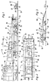
- Fig. 1 eine Seitenansicht eines an eine nur teilweise dargestellte Stopfmaschine angekuppelten Meßfahrzeuges mit einem auf diesem abstützbaren Satellitenwagen,
- Fig. 2 eine Teildraufsicht auf das Meßfahrzeug und
- Fig. 3 eine schematische Darstellung eines weiteren Ausführungsbeispieles eines Meßfahrzeuges.
- 1 is a side view of a measuring vehicle coupled to a tamping machine which is only partially shown, with a satellite car which can be supported thereon,
- Fig. 2 is a partial plan view of the measuring vehicle and
- Fig. 3 is a schematic representation of a further embodiment of a measuring vehicle.
Das in Fig. 1 ersichtliche Meßfahrzeug 1 weist einen Fahrzeugrahmen 2 mit einer Rahmenebene 3 auf, die parallel zu einer durch Radaufstandspunkte 4 von Schienenfahrwerken 5 gebildeten Bezugsebene parallel verläuft. Diese Parallelität bezieht sich auf den Normalfall, bei dem die Fahrwerksfederungen beider Schienenfahrwerke 5 im gleichen Ausmaß belastet sind. Auf der Rahmenebene 3 ist im Bereich des hinteren Maschinenendes 6 ein Verbrennungsmotor 7 angeordnet. Diesem ist in der - durch einen Pfeil 8 angedeuteten - Arbeitsrichtung des Meßfahrzeuges 1 eine Fahrkabine 9 mit einer Steuereinrichtung 10 unmittelbar vorgeordnet. Die Fahrkabine 9 befindet sich in einer Ausnehmung 11 des Fahrzeugrahmens 2. Die oberen, durch den Motor 7 und die Fahrkabine 9 gebildeten Umrißlinien 12 sind unterhalb einer Begrenzungsebene 13 angeordnet, die in Bezug auf die durch die Radaufstandspunkte 4 der Schienenfahrwerke 5 gebildete Bezugsebene bzw. die Rahmenebene 3 einen Winkel α von 5 bis 10° einschließt. Dabei bildet die Begrenzungsebene 13 mit der Rahmenebene 3 im in Arbeitsrichtung vorderen Ende des Meßfahrzeuges 1 eine sekrecht zur Maschinenlängsrichtung und parallel zur Rahmen- bzw. Bezugsebene verlaufende Schnittlinie 14. Das Meßfahrzeug 1 ist mit Hilfe eines eigenen Fahrantriebes 52 unabhängig verfahrbar.The
Unterhalb der Rahmenebene 3 und unmittelbar vor dem vorderen Schienenfahrwerk 5 ist ein durch Antriebe höhenverstellbar mit dem Fahrzeugrahmen 2 verbundener, Spurkranzräder 15 aufweisender Meßwagen 16 angeordnet. Auf diesem sind ein Laser-Empfänger 17 mit einer CCD-Matrix-Kamera, ein Querneigungsmesser 18 sowie zwei in Maschinenquerrichtung einander gegenüberliegende Video-Kameras 19 zur videotechnischen Abtastung des im Bereich jedes Spurkranzrades 15 befindlichen Schienenabschnittes angeordnet. Der Laser-Empfänger 17 ist durch Antriebe 20 höhen- und querverstellbar am Meßwagen 16 gelagert. Diesem ist außerdem noch eine Wegmeßeinrichtung 21 mit einer auf dem Schienenkopf abrollbaren Tastrolle zugeordnet.Beneath the frame level 3 and immediately in front of the
Die Länge des über das vordere Schienenfahrwerk 5 vorragenden Fahrzeugrahmens 2 ist größer als die Gesamtlänge eines Satellitenwagens 22 ausgebildet. Dieser ist durch eine Antriebe aufweisende Vorrichtung 23 von einem Gleis 24 abheb- und mit dem vorderen Ende des Fahrzeugrahmens 2 verbindbar. Wie mit strichpunktierten Linien angedeutet, befindet sich der Satellitenwagen 22 während der Überstellfahrt im über das vordere Schienenfahrwerk 5 vorragenden Abschnitt des Fahrzeugrahmens 2, so daß dieser ungehindert an eine weitere Maschine ankuppelbar ist.The length of the
Der Satellitenwagen 22 weist auf dem Gleis 24 verfahrbare Spurkranzräder, einen Hilfsmotor 25, eine Sitzgelegenheit 26 und einen Laser-Sender 27 auf. Dieser ist auf einer Querverstelleinrichtung 28 gelagert und jeweils bis zu 500 mm von der Gleismitte querverschiebbar.The
Die beiden Schienenfahrwerke 5 des Meßfahrzeuges 1 weisen zwischen Achslager und Fahrwerkrahmen befindliche, hydraulisch beaufschlagbare Blockierantriebe 29 auf, durch die der Einfluß der Fahrwerksfederung während des Meßvorganges ausschaltbar ist. Ein in Arbeitsrichtung am hinteren Maschinenende angeordneter Zughaken 30 ist für eine fernsteuerbare Lösung einer mit einer angeschlossenen Maschine gebildeten Kupplung ausgebildet.The two
Zur Bildung einer Anlage 31 zur Vermessung der Gleis-Ist-Lage sowie einer Gleislagekorrektur mit Hilfe der durch die Vermessung ermittelten Differenzwerte zwischen Ist- und Soll-Lage und einer Unterstopfung des in seiner Gleislage korrigierten Gleises ist das Meßfahzeug 1 für die Überstellfahrt mit einer Stopfmaschine 32 gekuppelt. Diese nur teilweise dargestellte und in üblicher Weise mit Stopfaggregaten, einem Gleishebe-Richtaggregat, einem Nivellier- und Richt-Bezugsystem 33 und einem Fahrantrieb 53 ausgestattete Stopfmaschine 32 ist in ihrem in Arbeitsrichtung vorderen Endbereich mit einer Fahrkabine 34 ausgestattet. Diese Fahrkabine 34 weist einen Sichtbereich 35 auf, von dem aus die Bedienungsperson während der Überstellfahrt freie Sicht auf das Gleis 24 hat. Diese freie Sicht ist trotz der Vorordnung des Meßfahrzeuges 1 dadurch gesichert, daß die oberen Umrißlinien 12 unterhalb der bereits genau definierten Begrenzungsebene 13 angeordnet sind.To form a
Unmittelbar vor dem Arbeitseinsatz der Anlage 31 wird der Zughaken 30 ferngesteuert gelöst und das Meßfahrzeug 1 mitsamt dem Satellitenwagen 22 ein- bis zweihundert Meter von der Stopfmaschine 32 distanziert auf dem Gleis 24 vorgefahren. Sobald der zu vermessende Gleisabschnitt erreicht ist, wird die Vorfahrt des Meßfahrzeuges 1 gestoppt und der Satellitenwagen 22 von der Vorrichtung 23 bzw. dem Fahrzeugrahmen 2 gelöst und auf das Gleis 24 abgesenkt. Anschließend wird der Satellitenwagen 22 bis zum nächsten Gleisfestpunkt vorgefahren und in Bezug auf eine auf der Schiene befindliche Farbmarkierung positioniert. Anschließend wird der Ist-Abstand und die Ist-Höhe des Gleises 24 zum Gleisfestpunkt vermessen. Die ermittelten Daten werden per Funk an das Meßfahrzeug 1 übertragen. Nach dieser Einmessung beim Gleisfestpunkt wird der Satellitenwagen 22 noch etwa 5 bis 10 m weiter vorgefahren und dort abgestellt. Der Laser-Sender 27 wird auf den Laser-Empfänger 17, der inzwischen mit dem Meßwagen 16 auf das Gleis 24 abgesenkt wurde, eingerichtet. Über eine geeignete mechanische Klemmvorrichtung wird dabei der Satellitenwagen 22 an einer Schiene des Gleises fixiert, so daß ein Verrücken durch vorüberfahrende Züge ausgeschlossen ist. Während der Messung besteht Funkverbindung über entsprechende Mobil-Funkgeräte zwischen den Bedienungspersonen des Stallitenwagens 22 des Meßfahrzeuges 1 und der Besatzung der Stopfmaschine 32.Immediately before the
Nachdem der Laser-Sender 27 auf den Empfänger 17 eingerichtet ist, beginnt das Meßfahrzeug 1 mit der Aufmessung des zwischen dem Meßfahrzeug 1 und dem Satellitenwagen 22 befindlichen Gleisabschnittes. Über die im Laser-Empfänger 17 befindliche CCD-Matrix-Kamera wird die Höhe und die Richtung gleichzeitig vermessen. Aus der Überhöhung der Spurweite der Position des Laser-Empfängers 17 und der Verstellwege sowie des zurückgelegten, durch die Wegmeßeinrichtung 21 gemessenen Weges werden die entsprechenden Ist-Pfeilhöhen im vorgegebenen Abstand errechnet. Die Berechnung wird erst dann gestartet, wenn das Meßfahrzeug 1 am unmittelbar vor dem Satellitenwagen 22 befindlichen Gleisfestpunkt angekommen und genau in Bezug auf diesen Gleisfestpunkt gestoppt wurde. Erst dann kann die beliebige Lage der durch den Laser-Sender 27 gebildeten Sehne rechnerisch auf die den Soll-Pfeilhöhen zugrundeliegende theoretische Sehne umgerechnet werden.After the
Während dieser Berechnung kann der Satellitenwagen 22 bereits wiederum mit Hilfe des eigenen Hilfsmotors 25 zum nächsten Gleisfestpunkt verfahren werden. Nach der Berechnung der Ist-Pfeilhöhen werden diese mit den gespeicherten Soll-Pfeilhöhen verglichen und die entsprechenden Verschiebe- und Höhenkorrekturwerte ermittelt. Diese Korrekturdaten werden dann mit Hilfe einer Funkteinrichtung 36 an die zentrale Steuereinrichtung 37 der Stopfmaschine 32 übertragen und können von dieser bzw. von einem automatischen Leitcomputer für eine entsprechende Steuerung der Antriebe des Gleishebe- und Richtaggregates weiterverarbeitet werden.During this calculation, the
Der vom Laser-Sender 27 erzeugte Laserstrahl wird nicht aufgespalten, sondern als im Querschnitt kreisförmiger Strahl auf den Empfänger 17 gerichtet. Dies bringt beim Empfang die Vorteile höherer Intensität und damit wird auch ein sicherer Empfang gewährleistet. Die Verstellmöglichkeit des Laser-Senders 27 mit Hilfe der Querverstelleinrichtung 28 bringt den Vorteil mit sich, daß es damit für den Empfänger 17 zu kleineren Pfeilhöhen kommt. Durch die sonstige Schräglage der Laser-Sehne müßte in einem größeren Bereich verstellt werden.The laser beam generated by the
Bei der CCD-Matrix-Kamera des Laser-Empfängers 17 handelt es sich um eine YZ-Verstelleinrichtung (Querverstellung Y, Höhenverstellung Z). Da die aktive Empfangsfläche der Kamera für den notwendigen Empfangsbereich zu klein ist, muß entsprechend nachgestellt werden. Dies erfolgt kontinuierlich mit einem Computer und einer entsprechenden Verstelleinheit. Dabei beträgt der Z-Verstellbereich 500 mm, der Y-Verstellbereich 1000 mm. Die Position der Kamera auf die Verstelleinheit wird über Absolut-Encoder gemessen. Der Laser-Punkt wird über eine Mattscheibe und eine Optik auf die CCD-Kamera projiziert und bezüglich seiner Lage durch einen Computer mit einem entsprechenden Programm errechnet und an einen Haupt-Computer 38 des Meßfahrzeuges 1 übertragen. Mit Hilfe der beiden am Meßwagen 16 befindlichen Videokameras 19 besteht die Möglichkeit, über ein in der Fahrkabine 9 erzeugtes Monitorbild die exakte Positionierung des Meßfahrzeuges 1 in Bezug zu einem entsprechenden Gleisfestpunkt durchzuführen. Dies erfolgt durch eine Positionierung der Radmitte des Meßwagens 16 auf eine am Schienenkopf und -steg angebrachte Farbmarkierung. Die durch die Spurkranzräder 15 gebildete Meßachse wird gleichzeitig als Teleskopachse ausgeführt, damit die Spurweite gemessen werden kann.The CCD matrix camera of the
Nach Beendigung des Arbeitseinsatzes wird die dreiteilige Anlage 31 zu einer Maschineneinheit verbunden, indem der Satellitenwagen 22 durch die Vorrichtung 23 mit dem vorderen Maschinenende des Meßfahrzeuges 1 verbunden und das Meßfahrzeug 1 selbst durch den Zughaken 30 an die Stopfmaschine 32 angekuppelt wird. Infolge der ungehinderten Sicht über das Meßfahrzeug 1 kann die Bedienungsperson die Anlage von der Fahrkabine 34 aus ungehindert in Richtung des Pfeiles 8 verfahren.After completion of the work, the three-
Eine in Fig. 3 ersichtliche Variante eines weiteren Meßfahrzeuges 39 weist einen auf Schienenfahrwerken 40 abgestützten Fahrzeugrahmen 42 mit einer parallel zur Gleisebene verlaufenden Rahmenebene 41 auf. Auf dem in Arbeitsrichtung hinteren Ende des Fahrzeugrahmens 42 ist eine zentrale Steuereinrichtung 43 mit einer Sitzgelegenheit 44 angeordnet. Unmittelbar davor befindet sich ein Abstellplatz für einen unabhängig verfahrbaren Satellitenwagen 45. Dieser ist auf in Maschinenlängsrichtung verlaufenden und mit dem Fahrzeugrahmen 42 verbundenen Schienen 46 und über eine im vorderen Endbereich des Fahrzeugrahmens angeordnete Rampe 47 auf ein Gleis 48 verfahrbar (siehe strichpunktierte Linien). Die Rampe 47 ist für die Überstellfahrt und den Arbeitseinsatz durch Antriebe in eine Ruheposition zurückverschwenkbar, bei der sie etwa parallel zur Rahmenebene 41 unmittelbar oberhalb des Fahrzeugrahmens 42 zu liegen kommt. Das Meßfahrzeug 39 ist mit Hilfe eines Motors 49 und eines Fahrantriebes 50 verfahrbar. Eine gemäß Anspruch 1 definierte Begrenzungsebene 51 schließt mit der Rahmenebene 41 einen Winkel von 8° ein. Der auf dem Fahrzeugrahmen 42 befindliche Satellitenwagen 45, die Steuereinrichtung 43 und die Sitzgelegenheit 44 befinden sich unterhalb dieser Begrenzungsebene 51, so daß von einer im hinteren Endbereich angeschlossenen Stopfmaschine für die gemeinsame Überstellfahrt eine ungehinderte Sicht auf das Gleis gegeben ist.A variant of a further measuring
Claims (15)
- A measuring vehicle (1, 39) for determining the actual track position with respect to the desired track position, comprising a vehicle frame (2, 42), supported on rail bogies (5, 40) and having a frame plane (3, 41) extending parallel to a reference plane formed by the wheel contact points (4), and comprising a satellite car (22, 45) transportable thereon and movable independently on the track, characterised in that the measuring vehicle (1, 39) and the satellite car (22, 45) are designed such that, when the satellite car (22, 45) is positioned at or on the vehicle frame (2, 42) of the measuring vehicle (1, 39), the upper contours (12) of the measuring vehicle (1, 39) and of the satellite car (22, 45) are disposed below a boundary plane (13, 51) which encloses an angle α of 5 to 10° with respect to a reference plane formed by the wheel contact points (4) of the rail bogies (5, 40), the boundary plane (13, 51) forming with the frame plane (3, 41) in the front end of the measuring vehicle (1, 39), in the working direction, a line of intersection (14) extending perpendicularly to the longitudinal direction of the machine and parallel to the reference plane, the boundary plane (13, 51) further extending through the visual range (35) of a driver's cabin (34) of a machine (32) coupled to the measuring vehicle (1, 39) at the rear end region thereof.
- A measuring vehicle according to claim 1, characterised in that only an engine (7) and an upper part of a driver's cabin (9) arranged in a recess of the vehicle frame (2) are provided above the frame plane (3) on the rear machine end, in the working direction, of the measuring vehicle (1), and the satellite car (22) is connected to the front machine end below the frame plane (3).
- A measuring vehicle according to one of claims 1 or 2, characterised in that there are provided below the frame plane (3) and immediately before the front rail bogie (5) a vertically adjustable measuring trolley (16) with flanged wheels (15) and a laser receiver (17) with a CCD-matrix camera and a device (23) for raising and releasably securing the satellite car (22).
- A measuring vehicle according to one of claims 1, 2 or 3, characterised in that a coupling hook (30) arranged on the rear machine end, in the working direction, is designed for the remotely controllable detachment of a coupling formed with a machine connected thereto.
- A measuring vehicle according to one of claims 1 to 4, characterised in that the rail bogies (5) have locking drives (29) which are located between the axle bearing and the bogie frame and which may be operated hydraulically.
- A measuring vehicle according to claim 3, characterised in that the laser receiver (17) is mounted on the measuring trolley (16) so as to be vertically and transversely adjustable by means of drives (20).
- A measuring vehicle according to claim 3, characterised in that a displacement measuring device (21) with a contact roller which may be rolled along the rail head is coordinated with the measuring trolley (16).
- A measuring vehicle according to claim 3, characterised in that two video cameras, positioned opposite one another in relation to the transverse direction of the machine, are arranged on the measuring trolley (16) to scan by video the section of the rail located in the region of each flanged wheel (15).
- A measuring vehicle according to claim 3, characterised in that the measuring trolley (16) is connected to a transverse inclination measuring device (18).
- A measuring vehicle according to one of claims 1 to 9, characterised in that arranged on the satellite car (22) which has a seating facility (26) and a motive drive (25) are a laser transmitter (27) and a distance measuring device for determining the vertical and lateral deviations of the track in relation to a track reference point.
- A measuring vehicle according to claim 10, characterised in that the laser transmitter (27) is mounted on a transverse adjustment device (28) and is displaceable transversely in each case up to 500 mm from the centre of the track.
- A measuring vehicle according to one of claims 1 to 11, characterised in that the length of the vehicle frame (2) projecting over the front rail bogie is designed to be greater than the total length of the satellite car (22).
- A measuring vehicle according to claim 1, characterised in that the front end of the vehicle frame (42) is provided with a ramp (47) which is capable of swivelling, for transferring the satellite car (45) from a transit position located on the frame plane (41) on to the track (48).
- An installation (31) for surveying the actual track position and a track position correction by means of the differential values, obtained by the surveying procedure, between the actual and the desired position and a tamping of the track whose track position has been corrected, comprising a measuring vehicle (1) according to claim 1, characterised by a three-part design, wherein, - viewed in the working direction of the installation - the rear part is formed by a tamping machine (32) which is coupled for combined transit with the measuring vehicle (1), on the front end region of which the satellite car (22) is secured.
- An installation according to claim 14, characterised in that the measuring vehicle (1) has a calculating unit (38) for determining the displacement- and vertical correction values and a radio device (36) for transmitting these values to a control device (37) located on the tamping machine (32) for the automatic control of lifting and aligning drives of a track lifting and aligning unit.
Applications Claiming Priority (2)
| Application Number | Priority Date | Filing Date | Title |
|---|---|---|---|
| AT1287/91 | 1991-06-27 | ||
| AT128791 | 1991-06-27 |
Publications (2)
| Publication Number | Publication Date |
|---|---|
| EP0520342A1 EP0520342A1 (en) | 1992-12-30 |
| EP0520342B1 true EP0520342B1 (en) | 1995-12-06 |
Family
ID=3510629
Family Applications (1)
| Application Number | Title | Priority Date | Filing Date |
|---|---|---|---|
| EP92110434A Expired - Lifetime EP0520342B1 (en) | 1991-06-27 | 1992-06-20 | Measuring vehicle |
Country Status (18)
| Country | Link |
|---|---|
| US (1) | US5301548A (en) |
| EP (1) | EP0520342B1 (en) |
| JP (1) | JP2865950B2 (en) |
| CN (1) | CN1044021C (en) |
| AT (1) | ATE131232T1 (en) |
| AU (1) | AU646743B2 (en) |
| CA (1) | CA2070791C (en) |
| CZ (1) | CZ278676B6 (en) |
| DE (1) | DE59204556D1 (en) |
| DK (1) | DK0520342T3 (en) |
| ES (1) | ES2081523T3 (en) |
| FI (1) | FI98314C (en) |
| HU (1) | HU212948B (en) |
| NO (1) | NO301599B1 (en) |
| PL (1) | PL168287B1 (en) |
| RU (1) | RU2041310C1 (en) |
| SK (1) | SK280109B6 (en) |
| ZA (1) | ZA924770B (en) |
Cited By (1)
| Publication number | Priority date | Publication date | Assignee | Title |
|---|---|---|---|---|
| RU2538482C1 (en) * | 2013-08-08 | 2015-01-10 | Открытое акционерное общество "БетЭлТранс" (ОАО "БЭТ") | Automated control system of geometric parameters of cross-ties |
Families Citing this family (38)
| Publication number | Priority date | Publication date | Assignee | Title |
|---|---|---|---|---|
| CZ285403B6 (en) * | 1995-03-16 | 1999-08-11 | Franz Plasser Bahnbaumaschinen-Industriegesellschaft M. B. H. | Track-building machine |
| AT405425B (en) * | 1997-08-20 | 1999-08-25 | Plasser Bahnbaumasch Franz | TRACK CONSTRUCTION MACHINE WITH A LASER REFERENCE SYSTEM AND METHOD |
| ATE254698T1 (en) * | 1998-03-27 | 2003-12-15 | Plasser Bahnbaumasch Franz | PROCEDURE FOR TRACK POSITION CORRECTION |
| US6161429A (en) * | 1998-10-13 | 2000-12-19 | Paveset America, Llc | Dual path profilograph |
| ATA18499A (en) * | 1999-02-10 | 2000-04-15 | Plasser Bahnbaumasch Franz | METHOD FOR CORRECTING THE POSITION OF A TRACK |
| DE50015765D1 (en) * | 1999-02-12 | 2009-12-03 | Plasser Bahnbaumasch Franz | Method for measuring a track |
| US6405141B1 (en) * | 2000-03-02 | 2002-06-11 | Ensco, Inc. | Dynamic track stiffness measurement system and method |
| SE516170C2 (en) * | 2000-03-29 | 2001-11-26 | Railvac Ab | Way to plan runway sides and laser measuring device |
| ITVE20000023A1 (en) * | 2000-05-12 | 2001-11-12 | Tecnogamma S A S Di Zanin E & | LASER EQUIPMENT FOR THE CONTROL OF THE RAILWAYS OF A RAILWAY LINE. |
| US9733625B2 (en) | 2006-03-20 | 2017-08-15 | General Electric Company | Trip optimization system and method for a train |
| US10308265B2 (en) | 2006-03-20 | 2019-06-04 | Ge Global Sourcing Llc | Vehicle control system and method |
| AT6219U3 (en) * | 2002-07-23 | 2004-07-26 | Plasser Bahnbaumasch Franz | METHOD FOR LOADING A LOADING TRAIN |
| AT5982U3 (en) * | 2002-11-13 | 2003-12-29 | Plasser Bahnbaumasch Franz | METHOD FOR SCANNING A BED PROFILE |
| US9950722B2 (en) | 2003-01-06 | 2018-04-24 | General Electric Company | System and method for vehicle control |
| US6804621B1 (en) * | 2003-04-10 | 2004-10-12 | Tata Consultancy Services (Division Of Tata Sons, Ltd) | Methods for aligning measured data taken from specific rail track sections of a railroad with the correct geographic location of the sections |
| US9956974B2 (en) | 2004-07-23 | 2018-05-01 | General Electric Company | Vehicle consist configuration control |
| US9828010B2 (en) | 2006-03-20 | 2017-11-28 | General Electric Company | System, method and computer software code for determining a mission plan for a powered system using signal aspect information |
| CN100371198C (en) * | 2006-03-27 | 2008-02-27 | 太原理工大学 | Stepping type rail track detection vehicle and detection method |
| US8914171B2 (en) | 2012-11-21 | 2014-12-16 | General Electric Company | Route examining system and method |
| CN101700777B (en) * | 2009-10-24 | 2011-09-28 | 株洲南车时代电气股份有限公司 | Track geometric parameter measurement car |
| CN102101478A (en) * | 2009-12-19 | 2011-06-22 | 襄樊金鹰轨道车辆有限责任公司 | Vehicle-mounted operating vehicle |
| WO2014026091A2 (en) | 2012-08-10 | 2014-02-13 | General Electric Company | Route examining system and method |
| US9702715B2 (en) | 2012-10-17 | 2017-07-11 | General Electric Company | Distributed energy management system and method for a vehicle system |
| CN103046442B (en) * | 2012-12-18 | 2015-03-11 | 北京二七轨道交通装备有限责任公司 | Grinding wagon laser positioning device and grinding wagon |
| US9255913B2 (en) | 2013-07-31 | 2016-02-09 | General Electric Company | System and method for acoustically identifying damaged sections of a route |
| AT514667B1 (en) * | 2013-08-07 | 2015-05-15 | Plasser & Theurer Export Von Bahnbaumaschinen Gmbh | Method for submerging a track |
| AT514718B1 (en) * | 2013-09-11 | 2015-06-15 | Plasser & Theurer Export Von Bahnbaumaschinen Gmbh | Method for correcting a track |
| US20150083914A1 (en) * | 2013-09-25 | 2015-03-26 | Nordco Inc. | Railway reference machine having a collapsible projector assembly |
| ES2646607T3 (en) * | 2014-06-27 | 2017-12-14 | Hp3 Real Gmbh | Railroad measuring device |
| CN104652197A (en) * | 2015-02-13 | 2015-05-27 | 中铁第一勘察设计院集团有限公司 | Separated traveling wheel driving device for high speed railway track measurement instrument |
| WO2016153486A1 (en) * | 2015-03-24 | 2016-09-29 | Harsco Technologies LLC | Moveable seat on a rail vehicle |
| AT518839B1 (en) * | 2016-07-11 | 2018-12-15 | Plasser & Theurer Exp Von Bahnbaumaschinen G M B H | System and method for measuring a track |
| AT519575B1 (en) * | 2017-02-15 | 2018-08-15 | Plasser & Theurer Export Von Bahnbaumaschinen Gmbh | Track measuring vehicle and method for detecting a vertical track position |
| AT519784B1 (en) * | 2017-03-17 | 2019-11-15 | Plasser & Theurer Export Von Bahnbaumaschinen Gmbh | Machine and method for profiling and distributing gravel of a track |
| CN110116734A (en) * | 2019-05-07 | 2019-08-13 | 中国铁建重工集团股份有限公司 | Magnetic levitation track Operation Van |
| CN112442927A (en) * | 2019-09-02 | 2021-03-05 | 中国铁道科学研究院集团有限公司铁道建筑研究所 | Method for measuring front end deviation of tamping car |
| RU199383U1 (en) * | 2020-02-04 | 2020-08-31 | Общество с ограниченной ответственностью "РН-Пурнефтегаз" | CARRIAGE FOR REMOTE MOVEMENT OF THE REFLECTOR ON THE RAIL |
| CN114987565B (en) * | 2022-06-17 | 2023-08-04 | 杭州申昊科技股份有限公司 | Rail flaw detection vehicle with obstacle crossing function |
Family Cites Families (3)
| Publication number | Priority date | Publication date | Assignee | Title |
|---|---|---|---|---|
| GB1154311A (en) * | 1965-03-23 | 1969-06-04 | Canron Ltd | Railway Track Lifting Apparatus |
| US3750299A (en) * | 1969-01-22 | 1973-08-07 | Plasser Bahnbaumasch Franz | Track apparatus with laser beam reference |
| DE3562105D1 (en) * | 1985-08-22 | 1988-05-11 | Plasser Bahnbaumasch Franz | Mobile track machine for measuring respectively recording or correcting the track position with laser beams respectively laser plans |
-
1992
- 1992-06-03 RU SU925011692A patent/RU2041310C1/en active
- 1992-06-04 NO NO922200A patent/NO301599B1/en not_active IP Right Cessation
- 1992-06-09 CA CA002070791A patent/CA2070791C/en not_active Expired - Lifetime
- 1992-06-18 US US07/900,910 patent/US5301548A/en not_active Expired - Lifetime
- 1992-06-20 EP EP92110434A patent/EP0520342B1/en not_active Expired - Lifetime
- 1992-06-20 AT AT92110434T patent/ATE131232T1/en not_active IP Right Cessation
- 1992-06-20 ES ES92110434T patent/ES2081523T3/en not_active Expired - Lifetime
- 1992-06-20 DK DK92110434.5T patent/DK0520342T3/en not_active Application Discontinuation
- 1992-06-20 DE DE59204556T patent/DE59204556D1/en not_active Expired - Fee Related
- 1992-06-23 PL PL92294986A patent/PL168287B1/en not_active IP Right Cessation
- 1992-06-24 CN CN92105036A patent/CN1044021C/en not_active Expired - Fee Related
- 1992-06-25 HU HU9202115A patent/HU212948B/en not_active IP Right Cessation
- 1992-06-26 CZ CS921983A patent/CZ278676B6/en not_active IP Right Cessation
- 1992-06-26 JP JP4169393A patent/JP2865950B2/en not_active Expired - Fee Related
- 1992-06-26 AU AU18621/92A patent/AU646743B2/en not_active Ceased
- 1992-06-26 ZA ZA924770A patent/ZA924770B/en unknown
- 1992-06-26 FI FI922974A patent/FI98314C/en active
- 1992-06-26 SK SK1983-92A patent/SK280109B6/en not_active IP Right Cessation
Cited By (1)
| Publication number | Priority date | Publication date | Assignee | Title |
|---|---|---|---|---|
| RU2538482C1 (en) * | 2013-08-08 | 2015-01-10 | Открытое акционерное общество "БетЭлТранс" (ОАО "БЭТ") | Automated control system of geometric parameters of cross-ties |
Also Published As
| Publication number | Publication date |
|---|---|
| CN1044021C (en) | 1999-07-07 |
| HUT64276A (en) | 1993-12-28 |
| CZ278676B6 (en) | 1994-04-13 |
| SK280109B6 (en) | 1999-08-06 |
| CZ198392A3 (en) | 1993-01-13 |
| DK0520342T3 (en) | 1996-01-08 |
| ES2081523T3 (en) | 1996-03-16 |
| US5301548A (en) | 1994-04-12 |
| HU212948B (en) | 1996-12-30 |
| DE59204556D1 (en) | 1996-01-18 |
| EP0520342A1 (en) | 1992-12-30 |
| ZA924770B (en) | 1993-03-31 |
| JP2865950B2 (en) | 1999-03-08 |
| RU2041310C1 (en) | 1995-08-09 |
| AU646743B2 (en) | 1994-03-03 |
| NO301599B1 (en) | 1997-11-17 |
| FI922974A (en) | 1992-12-28 |
| FI98314B (en) | 1997-02-14 |
| CN1067938A (en) | 1993-01-13 |
| HU9202115D0 (en) | 1992-10-28 |
| CA2070791C (en) | 2002-12-31 |
| NO922200D0 (en) | 1992-06-04 |
| PL168287B1 (en) | 1996-01-31 |
| NO922200L (en) | 1992-12-28 |
| PL294986A1 (en) | 1992-12-28 |
| FI922974A0 (en) | 1992-06-26 |
| AU1862192A (en) | 1993-01-07 |
| SK198392A3 (en) | 1994-08-10 |
| FI98314C (en) | 1997-05-26 |
| JPH05202506A (en) | 1993-08-10 |
| ATE131232T1 (en) | 1995-12-15 |
| CA2070791A1 (en) | 1992-12-18 |
Similar Documents
| Publication | Publication Date | Title |
|---|---|---|
| EP0520342B1 (en) | Measuring vehicle | |
| EP1028325B1 (en) | Method of surveying a train track | |
| EP0213253B1 (en) | Mobile track machine for measuring respectively recording or correcting the track position with laser beams respectively laser plans | |
| EP3358079B1 (en) | Method and device for measuring and computing a track bed | |
| AT403066B (en) | METHOD FOR DETERMINING THE DEVIATIONS OF THE ACTUAL LOCATION OF A TRACK SECTION | |
| EP0511191B1 (en) | System to measure the position of a rail track with respect to a fixed point | |
| DE3137194A1 (en) | TRACKABLE DEVICE FOR DETERMINING THE LOCATION OF THE NEIGHBORHOOD TRACK | |
| EP2839078B1 (en) | Machine for maintaining a track | |
| AT516343B1 (en) | Method for determining the position of the overhead line or the busbar for vehicles | |
| EP0424811A1 (en) | Reference system for railway track working machines | |
| EP1270814B1 (en) | Track building machine and method for measuring a track | |
| EP0732451A1 (en) | Work vehicle for carrying out railway work | |
| EP1028193B1 (en) | Correction method for the position of a railway track | |
| EP0652325B1 (en) | Railroad maintenance machine for correcting the position of the track | |
| EP1001085A1 (en) | Method and apparatus for tamping a railway track | |
| EP4251491A1 (en) | Method and system for ascertaining correction values for correcting the position of a track | |
| DE102006027852B4 (en) | Gleismeßfahrzeug | |
| CA1095333A (en) | Mobile track leveling, lining and tamping machine | |
| AT514718A1 (en) | Method for correcting a track | |
| EP0731217B1 (en) | Tamping machine, assembly and method for tamping a railway track | |
| EP0722013B1 (en) | Method and apparatus for carrying out railway track works | |
| EP4130379A1 (en) | Method for correcting the lateral and vertical distances between a railway platform edge of a railway platform and a rail axis | |
| DE1816224C3 (en) | ||
| EP4008838A1 (en) | Tamping machine for tamping track sleepers | |
| DE1709433C3 (en) | Track tamping machine |
Legal Events
| Date | Code | Title | Description |
|---|---|---|---|
| PUAI | Public reference made under article 153(3) epc to a published international application that has entered the european phase |
Free format text: ORIGINAL CODE: 0009012 |
|
| AK | Designated contracting states |
Kind code of ref document: A1 Designated state(s): AT BE CH DE DK ES FR GB IT LI NL SE |
|
| 17P | Request for examination filed |
Effective date: 19930518 |
|
| 17Q | First examination report despatched |
Effective date: 19940613 |
|
| GRAA | (expected) grant |
Free format text: ORIGINAL CODE: 0009210 |
|
| AK | Designated contracting states |
Kind code of ref document: B1 Designated state(s): AT BE CH DE DK ES FR GB IT LI NL SE |
|
| REF | Corresponds to: |
Ref document number: 131232 Country of ref document: AT Date of ref document: 19951215 Kind code of ref document: T |
|
| ITF | It: translation for a ep patent filed |
Owner name: ING. A. GIAMBROCONO & C. S.R.L. |
|
| REG | Reference to a national code |
Ref country code: DK Ref legal event code: T3 |
|
| REF | Corresponds to: |
Ref document number: 59204556 Country of ref document: DE Date of ref document: 19960118 |
|
| GBT | Gb: translation of ep patent filed (gb section 77(6)(a)/1977) |
Effective date: 19960116 |
|
| REG | Reference to a national code |
Ref country code: CH Ref legal event code: NV Representative=s name: DIPL.-ING. ETH H. R. WERFFELI PATENTANWALT |
|
| REG | Reference to a national code |
Ref country code: ES Ref legal event code: FG2A Ref document number: 2081523 Country of ref document: ES Kind code of ref document: T3 |
|
| ET | Fr: translation filed | ||
| PLBE | No opposition filed within time limit |
Free format text: ORIGINAL CODE: 0009261 |
|
| STAA | Information on the status of an ep patent application or granted ep patent |
Free format text: STATUS: NO OPPOSITION FILED WITHIN TIME LIMIT |
|
| 26N | No opposition filed | ||
| REG | Reference to a national code |
Ref country code: GB Ref legal event code: IF02 |
|
| PGFP | Annual fee paid to national office [announced via postgrant information from national office to epo] |
Ref country code: NL Payment date: 20090528 Year of fee payment: 18 Ref country code: DK Payment date: 20090526 Year of fee payment: 18 |
|
| PGFP | Annual fee paid to national office [announced via postgrant information from national office to epo] |
Ref country code: FR Payment date: 20090526 Year of fee payment: 18 Ref country code: SE Payment date: 20090528 Year of fee payment: 18 |
|
| PGFP | Annual fee paid to national office [announced via postgrant information from national office to epo] |
Ref country code: BE Payment date: 20090602 Year of fee payment: 18 |
|
| PGFP | Annual fee paid to national office [announced via postgrant information from national office to epo] |
Ref country code: CH Payment date: 20090526 Year of fee payment: 18 |
|
| PGFP | Annual fee paid to national office [announced via postgrant information from national office to epo] |
Ref country code: DE Payment date: 20090811 Year of fee payment: 18 |
|
| PGFP | Annual fee paid to national office [announced via postgrant information from national office to epo] |
Ref country code: ES Payment date: 20100519 Year of fee payment: 19 |
|
| PGFP | Annual fee paid to national office [announced via postgrant information from national office to epo] |
Ref country code: AT Payment date: 20100511 Year of fee payment: 19 Ref country code: IT Payment date: 20100624 Year of fee payment: 19 |
|
| PGFP | Annual fee paid to national office [announced via postgrant information from national office to epo] |
Ref country code: GB Payment date: 20100428 Year of fee payment: 19 |
|
| BERE | Be: lapsed |
Owner name: FRANZ *PLASSER BAHNBAUMASCHINEN- INDUSTRIEGESELLSC Effective date: 20100630 |
|
| REG | Reference to a national code |
Ref country code: NL Ref legal event code: V1 Effective date: 20110101 |
|
| REG | Reference to a national code |
Ref country code: CH Ref legal event code: PL Ref country code: DK Ref legal event code: EBP |
|
| EUG | Se: european patent has lapsed | ||
| REG | Reference to a national code |
Ref country code: FR Ref legal event code: ST Effective date: 20110228 |
|
| PG25 | Lapsed in a contracting state [announced via postgrant information from national office to epo] |
Ref country code: CH Free format text: LAPSE BECAUSE OF NON-PAYMENT OF DUE FEES Effective date: 20100630 Ref country code: LI Free format text: LAPSE BECAUSE OF NON-PAYMENT OF DUE FEES Effective date: 20100630 Ref country code: DE Free format text: LAPSE BECAUSE OF NON-PAYMENT OF DUE FEES Effective date: 20110101 |
|
| PG25 | Lapsed in a contracting state [announced via postgrant information from national office to epo] |
Ref country code: FR Free format text: LAPSE BECAUSE OF NON-PAYMENT OF DUE FEES Effective date: 20100630 Ref country code: NL Free format text: LAPSE BECAUSE OF NON-PAYMENT OF DUE FEES Effective date: 20110101 |
|
| PG25 | Lapsed in a contracting state [announced via postgrant information from national office to epo] |
Ref country code: BE Free format text: LAPSE BECAUSE OF NON-PAYMENT OF DUE FEES Effective date: 20100630 |
|
| PG25 | Lapsed in a contracting state [announced via postgrant information from national office to epo] |
Ref country code: DK Free format text: LAPSE BECAUSE OF NON-PAYMENT OF DUE FEES Effective date: 20100630 |
|
| GBPC | Gb: european patent ceased through non-payment of renewal fee |
Effective date: 20110620 |
|
| PG25 | Lapsed in a contracting state [announced via postgrant information from national office to epo] |
Ref country code: IT Free format text: LAPSE BECAUSE OF NON-PAYMENT OF DUE FEES Effective date: 20110620 Ref country code: AT Free format text: LAPSE BECAUSE OF NON-PAYMENT OF DUE FEES Effective date: 20110620 |
|
| REG | Reference to a national code |
Ref country code: AT Ref legal event code: MM01 Ref document number: 131232 Country of ref document: AT Kind code of ref document: T Effective date: 20110620 |
|
| PG25 | Lapsed in a contracting state [announced via postgrant information from national office to epo] |
Ref country code: GB Free format text: LAPSE BECAUSE OF NON-PAYMENT OF DUE FEES Effective date: 20110620 |
|
| REG | Reference to a national code |
Ref country code: ES Ref legal event code: FD2A Effective date: 20120717 |
|
| PG25 | Lapsed in a contracting state [announced via postgrant information from national office to epo] |
Ref country code: ES Free format text: LAPSE BECAUSE OF NON-PAYMENT OF DUE FEES Effective date: 20110621 |
|
| PG25 | Lapsed in a contracting state [announced via postgrant information from national office to epo] |
Ref country code: SE Free format text: LAPSE BECAUSE OF NON-PAYMENT OF DUE FEES Effective date: 20100621 |