EP0516772B1 - Process for digital video display and reproduction by the helical-scannning method - Google Patents
Process for digital video display and reproduction by the helical-scannning method Download PDFInfo
- Publication number
- EP0516772B1 EP0516772B1 EP91920296A EP91920296A EP0516772B1 EP 0516772 B1 EP0516772 B1 EP 0516772B1 EP 91920296 A EP91920296 A EP 91920296A EP 91920296 A EP91920296 A EP 91920296A EP 0516772 B1 EP0516772 B1 EP 0516772B1
- Authority
- EP
- European Patent Office
- Prior art keywords
- data
- row
- column
- test symbols
- memory
- Prior art date
- Legal status (The legal status is an assumption and is not a legal conclusion. Google has not performed a legal analysis and makes no representation as to the accuracy of the status listed.)
- Expired - Lifetime
Links
Images


Classifications
-
- H—ELECTRICITY
- H04—ELECTRIC COMMUNICATION TECHNIQUE
- H04N—PICTORIAL COMMUNICATION, e.g. TELEVISION
- H04N5/00—Details of television systems
- H04N5/76—Television signal recording
- H04N5/91—Television signal processing therefor
- H04N5/92—Transformation of the television signal for recording, e.g. modulation, frequency changing; Inverse transformation for playback
- H04N5/926—Transformation of the television signal for recording, e.g. modulation, frequency changing; Inverse transformation for playback by pulse code modulation
- H04N5/9265—Transformation of the television signal for recording, e.g. modulation, frequency changing; Inverse transformation for playback by pulse code modulation with processing of the sound signal
- H04N5/9267—Transformation of the television signal for recording, e.g. modulation, frequency changing; Inverse transformation for playback by pulse code modulation with processing of the sound signal using time division multiplex of the PCM audio and PCM video signals
- H04N5/9268—Transformation of the television signal for recording, e.g. modulation, frequency changing; Inverse transformation for playback by pulse code modulation with processing of the sound signal using time division multiplex of the PCM audio and PCM video signals with insertion of the PCM audio signals in the vertical blanking interval of the PCM video signal
-
- H—ELECTRICITY
- H04—ELECTRIC COMMUNICATION TECHNIQUE
- H04N—PICTORIAL COMMUNICATION, e.g. TELEVISION
- H04N5/00—Details of television systems
- H04N5/76—Television signal recording
- H04N5/91—Television signal processing therefor
- H04N5/93—Regeneration of the television signal or of selected parts thereof
- H04N5/937—Regeneration of the television signal or of selected parts thereof by assembling picture element blocks in an intermediate store
-
- H—ELECTRICITY
- H04—ELECTRIC COMMUNICATION TECHNIQUE
- H04N—PICTORIAL COMMUNICATION, e.g. TELEVISION
- H04N5/00—Details of television systems
- H04N5/76—Television signal recording
- H04N5/91—Television signal processing therefor
- H04N5/93—Regeneration of the television signal or of selected parts thereof
- H04N5/94—Signal drop-out compensation
- H04N5/945—Signal drop-out compensation for signals recorded by pulse code modulation
Definitions
- the invention relates to a method and an arrangement for recording and reproducing digital data blocks, in particular for digital video recording, on or of individual tracks of a magnetic tape according to the helical track method.
- Digital recording methods are becoming increasingly important when recording video signals. Digital recording brings clear advantages in terms of image and sound quality. These quality advantages are particularly evident in the dubbing process, since the original quality is largely preserved. There are also advantages in processing. Trick effects that had to be carried out in one work step if possible with analog recording in order not to have to accept any noticeable loss in quality can now be carried out over several work steps.
- the digital recording methods receive a system-related advantage in particular through the possibility of error correction, which protects both against single-bit errors or single-symbol errors, so-called random errors, and against error bundles, i.e. Offers burst errors. These errors can be recognized on the reproduction side and can usually also be corrected. Errors that cannot be corrected can be reduced by interpolating the incorrect data words from neighboring data words.
- the product code offers a widespread and very effective error correction. This code can be used to correct both random errors and burst errors.
- the description of the invention relates to this product code, although other error codes, for example cascaded codes, are also conceivable.
- the data are arranged in blocks there, a block consisting of n 1 rows with n 2 symbols and n 2 columns with n 1 symbols and a row n 2 -k 2 uncoded data symbols and k 2 check symbols and a column contains n 1 - k 1 uncoded data symbols and k 1 test symbols.
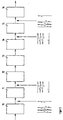
- a block code is generated with an arrangement according to FIG. 2.
- Digital video or audio data is initially present at the input of the encoder 10.
- Each n 1 - k 1 uncoded data symbols are supplemented by k 1 test symbols, for example a Reed-Solomon code (RS code), and written into a column of the memory 11. In this way, n 2 - k 2 columns are written into the memory 11.
- RS code Reed-Solomon code
- the data symbols contained in it are then read out line by line and fed to an encoder 12.
- a further RS test code consisting of k 2 test symbols is added to each line read, so that a block code corresponding to FIG. 1 is created.
- the digital signals coded in this way are recorded on a magnetic tape 13.
- these signals are decoded again using the decoders 14 and 16 and the memory 15 in the reverse order to the recording, so that at the output of the decoder 16 the data are present which were applied to the encoder 10 on the recording side before the encoding process.
- the digital data is recorded on a track using the helical track recording method, the recording taking place in the order in which it is obtained from the encoder 12.
- An important aspect in the arrangement of the data blocks on a track of a digital helical trace recording device is the image reproduction quality in the case of special functions, in particular in the case of playback with a changed tape speed, that is to say slow motion or search mode.
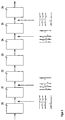
- the invention is based on an arrangement according to FIG. 3, which relates to the functional principle of the Arrangement according to Figure 2 corresponds.
- the input data pass through a line-oriented encoder 20, which adds line-oriented test symbols (P test code) to a corresponding number of data.
- This data is written line by line into a memory 21, one line each containing the useful information and the line-oriented test symbols. If the memory 21 contains a certain number of rows, the data are read out column by column from this memory and fed to a column-oriented encoder 22 which adds column-oriented test symbols (Q test code) to each column. Then the data is written on the magnetic tape 23. During playback, the data are read from the tape and the Q check code is evaluated in a column-oriented decoder 24.
- Data that has not been corrected is marked.
- the data leaving the column-oriented decoder are written column-by-column into the memory 25, from which they are read line by line again and fed to the line-oriented decoder 26, which evaluates the P check code.
- the data recorded by the coding in a different order are available again in their original order.
- the data first pass through the column-oriented decoder, which can correct random errors and possibly short burst errors, but which cannot correct longer burst errors, such as those that occur in particular in the case of special functions.
- the line-oriented decoder does not work with special functions, so that error-free line-oriented blocks cannot be obtained when the data are recorded in a different order.
- the object is achieved in the inventive method according to claim 1.
- the data is recorded in an unchanged order, which has advantages in data reduction processes e.g. with the help of a transformation coding, since there is no splitting of uncorrectable burst errors into random errors.
- a second memory is inserted after the column-oriented encoder, into which the data are read in columns and read out line by line.
- the data are first fed to the row-oriented decoder and then after the sorting in a memory to the column-oriented decoder.
- the data is then re-sorted into the original order using a second memory on the playback side.
- the second decoder works again, in this case the column-oriented decoder does not, but a large part of the row-oriented blocks in which the data are corrected in the correct order are available.
- the column-oriented test symbols which cannot be evaluated in the case of special functions are recorded at the beginning or at the end or at both ends of a track.
- the audio data that is also not required for special video functions can be recorded at the opposite end or beginning of a track. This method is particularly advantageous since the data that are not required or cannot be evaluated in the case of special functions are at the tape inlet or at the tape outlet of the magnetic head, where they can often not be read correctly due to incorrect tracking and poor tape / head contact in the special functions.
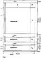
- FIG. 4 shows a block arrangement of the data as it comes to lie in a track, according to this figure the column-oriented test code at the tape entry and the audio data at the tape exit of the magnetic head.
- the reverse arrangement is also conceivable according to the invention.
- the data depth of the individual segments and sub-segments in bytes is given as an example without restricting the general validity.
- the code block as it comes to lie on a track consists of 3 segments.
- a video segment comprising 312 bytes in the column-oriented direction and 96 bytes in the row-oriented direction, two audio segments each containing 11 bytes in the column-oriented direction and 96 bytes in the row-oriented direction.
- run-in and run-out areas are also specified, each of which is 96 bytes long in a row-oriented direction.
- the length of the run-in areas is 4 bytes
- the run-out area is 1 byte in the column-oriented direction.
- the run in areas are before the video segment, after the video segment, i.e. before the first audio segment and between the audio segments. After the second audio segment is the run out area.
- the column-oriented test symbols Q are located not in the column direction following the video user data, but they are placed before the video user data so that they come to rest in the track at the tape inlet of the magnetic head.
- the line-oriented test symbols P are in FIG. 4, as in the prior art, following the video user data in a line-oriented direction.
- the structure of the audio segments is the same as the structure of the video segment, with the amount of data contained in the audio segments being significantly less than the amount of data contained in the video segment.
- the data volume of the two audio segments corresponds approximately to the data volume of the column-oriented test code Q.
- the position of the data on a track of the magnetic tape is shown in FIG. According to the direction of the video head movement, the test symbols of the column-oriented test code are located at the tape inlet of the magnetic head directly after the first run in area. The remaining data of the video segment then follow and the two audio segments are located at the tape outlet.
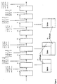
- FIG. 6 shows an arrangement according to the invention for carrying out the recording method described above.
- This arrangement consists of a line-oriented encoder 1 on which the input data are present.
- the row-oriented encoder is connected to a memory 2, which is further connected to the column-oriented encoder 3.
- a data connection leads from the column-oriented egg encoder 3 to the memory 4.
- the data from this memory are recorded on the magnetic tape 5.
- the data read from the magnetic tape 5 are fed to the line-oriented decoder 6, which is further connected to the memory 7.
- the data from the memory 7 are fed to the column-oriented decoder 8 and, following the decoding, are written into the memory 9, from which they are fed as output data for further signal processing.
- the memory contents are also shown schematically for better understanding.
- the user data is available at the input of the line-oriented encoder 1. This input data passes through the line-oriented decoder and is then written line by line into the memory 2. At the end of each line, the line-oriented encoder adds 1 test symbols, so that a block with line-oriented code words is created, which is composed of user data and line-oriented test symbols.
- the data are read out in columns from the memory 2 and fed to the column-oriented encoder 3.
- the order of the column-oriented encoder 3 data is changed and additionally expanded by the row-oriented test symbols.
- column-oriented test symbols are added at the end of each column and written into the memory 4 in columns, so that a product code block is stored in the second memory, which is composed of the useful data in their original order, supplemented by the row and column-oriented test symbols. So that the column-oriented test symbols come to rest on the tape inlet of the magnetic head, these column-oriented test symbols are first read line by line from top to bottom from the memory 4 and recorded on the magnetic tape and then the remaining data are read line by line from top to bottom and recorded.
- the data read from the tape first pass through the line-oriented decoder 6, which can correct random errors and short burst errors by evaluating the P-test symbols and identifies non-corrected errors.
- the data are then written line by line and without the line-oriented test code into the memory 7, the Q test symbols of the column-oriented test code obtained first being written into the lower memory area and the user data into the upper memory area, in each case from top to bottom.
- the data are read out from the memory 7 in columns and fed to the column-oriented decoder 8, which corrects the still existing errors on the basis of the column-oriented test symbols and error identification.
- the data thus obtained are again written into the memory 9 in columns, in which they are then present in their original order and without test symbols.
- the line-oriented decoder 6 When playing at a changed speed, for example search or slow motion, only the line-oriented decoder 6 works correctly. It can be used to correct random errors and, if appropriately dimensioned, short burst errors. Data blocks that have not been corrected are marked. The column-oriented decoder does not work, but a large part of the row blocks is available without errors. Longer burst errors that cannot be corrected are to be expected especially at the tape entry and exit of the magnetic head. In the method according to the invention, however, the column-oriented test symbols, which cannot be evaluated anyway, and the audio data, which are also not evaluated when playing at a changed speed, are located at these points on a recording track.
- the useful data are recorded on the tape in the same chronological order as they are at the input, that is to say burst errors are not broken down into individual errors on the reproduction side, since for example in the case of a transformation coding an individual error has the same effects as a burst error.
- the order of the data recorded on the tape is to be changed compared to the order at the input, this can be done in a simple manner by adding an additional memory on the recording side and adding a memory on the playback side.
Abstract
Description
Die Erfindung betrifft ein Verfahren und eine Anordnung zur Aufzeichnung und Wiedergabe von digitalen Datenblöcken, insbesondere für die digitale Videoaufzeichnung, auf bzw. von einzelnen Spuren eines Magnetbandes nach dem Schrägspurverfahren.The invention relates to a method and an arrangement for recording and reproducing digital data blocks, in particular for digital video recording, on or of individual tracks of a magnetic tape according to the helical track method.
Bei der Aufzeichnung von Videosignalen gewinnen digitale Aufzeichnungsverfahren immer mehr an Bedeutung. Die digitale Aufzeichnung bringt deutliche Vorteile bei der Bild-, aber auch der Tonqualität. Diese Qualitätsvorteile werden insbesondere beim Überspielvorgang deutlich, da die ursprüngliche Qualität weitestgehend erhalten bleibt. Weiterhin ergeben sich Vorteile bei der Bearbeitung. Trickeffekte, die bei analoger Aufzeichnung möglichst in einem Arbeitsgang ausgeführt werden mußten, um nicht merkliche Qualitätseinbußen hinnehmen zu müssen, können jetzt über mehrere Arbeitsgänge ausgeführt werden.Digital recording methods are becoming increasingly important when recording video signals. Digital recording brings clear advantages in terms of image and sound quality. These quality advantages are particularly evident in the dubbing process, since the original quality is largely preserved. There are also advantages in processing. Trick effects that had to be carried out in one work step if possible with analog recording in order not to have to accept any noticeable loss in quality can now be carried out over several work steps.
Einen systembedingten Vorteil erhalten die digitalen Aufzeichnungsverfahren insbesondere durch die Möglichkeit der Fehlerkorrektur, die sowohl Schutz gegen Einzelbitfehler bzw. Einzelsymbolfehler, sogenannte Random-Fehler, als auch gegen Fehlerbündel, d.h. Burstfehler bietet. Diese Fehler können wiedergabeseitig erkannt und meist auch korrigiert werden. Nicht korrigierbare Fehler können abgeschwächt werden, indem aus benachbarten Datenworten die fehlerhaften Datenworte interpoliert werden.The digital recording methods receive a system-related advantage in particular through the possibility of error correction, which protects both against single-bit errors or single-symbol errors, so-called random errors, and against error bundles, i.e. Offers burst errors. These errors can be recognized on the reproduction side and can usually also be corrected. Errors that cannot be corrected can be reduced by interpolating the incorrect data words from neighboring data words.
Eine weit verbreitete und sehr effektive Fehlerkorrektur bietet der Produktcode. Mit diesem Code lassen sich sowohl Random-Fehler als auch Burstfehler korrigieren. Im folgenden bezieht sich die Beschreibung der Erfindung auf diesen Produktcode, wobei andere Fehlercodes, beispielsweise kaskadierte Codes, ebenfalls denkbar sind.The product code offers a widespread and very effective error correction. This code can be used to correct both random errors and burst errors. In the following, the description of the invention relates to this product code, although other error codes, for example cascaded codes, are also conceivable.
Die Fehlerkorrektur mittels Produktcode wird beispielsweise in dem Artikel "The SMPTE Type D-1 Digital Television Tape Recorder-Error control" von S.H. Wilkinson, SMPTE-Journal, November 1986, beschrieben.Error correction using product code is described, for example, in the article "The SMPTE Type D-1 Digital Television Tape Recorder-Error control" by S.H. Wilkinson, SMPTE Journal, November 1986.
Gemäß Figur 1 werden dort die Daten blockweise angeordnet, wobei ein Block aus n1 Zeilen mit n2 Symbolen und n2 Spalten mit n1 Symbolen besteht und eine Zeile n2 - k2 uncodierte Datensymbole und k2 Prüfsymbole und eine Spalte n1 - k1 uncodierte Datensymbole und k1 Prüfsymbole enthält. Die Erstellung eines solchen Blockcodes erfolgt mit einer Anordnung nach Figur 2. Am Eingang des Encoders 10 liegen zunächst digitale Videooder Audiodaten an. Jeweils n1- k1 uncodierte Datensymbole werden durch k1 Prüfsymbole, beispielsweise einem Reed-Solomon-Code (R-S-Code), ergänzt und in eine Spalte des Speichers 11 geschrieben. Auf diese Weise werden n2 - k2 Spalten in den Speicher 11 geschrieben. Anschließend werden die in ihm enthaltenen Datensymbole zeilenweise ausgelesen und einem Encoder 12 zugeführt. In diesem Encoder 12 wird jeder ausgelesenen Zeile ein weiterer R-S-Prüfcode, der aus k2 Prüfsymbolen besteht, zugefügt, so daß ein Blockcode entsprechend Figur 1 entsteht. Die auf diese Weise codierten digitalen Signale werden auf ein Magnetband 13 aufgezeichnet. Bei der Wiedergabe werden diese Signale mit Hilfe der Decoder 14 und 16 und des Speichers 15 in zur Aufzeichnung umgekehrter Reihenfolge wieder decodiert, so daß am Ausgang des Decoders 16 die Daten vorliegen, welche vor dem Codiervorgang auf der Aufzeichnungsseite am Encoder 10 angelegen haben.According to FIG. 1, the data are arranged in blocks there, a block consisting of n 1 rows with n 2 symbols and n 2 columns with n 1 symbols and a row n 2 -k 2 uncoded data symbols and k 2 check symbols and a column contains n 1 - k 1 uncoded data symbols and k 1 test symbols. Such a block code is generated with an arrangement according to FIG. 2. Digital video or audio data is initially present at the input of the
Entsprechend der Struktur der Datenblöcke werden die digitalen Daten nach dem Schrägspuraufzeichnungsverfahren auf eine Spur aufgezeichnet, wobei die Aufzeichnung in der Reihenfolge erfolgt, wie sie vom Encoder 12 erhalten wird.According to the structure of the data blocks, the digital data is recorded on a track using the helical track recording method, the recording taking place in the order in which it is obtained from the
Bei der Beschreibung von Figur 1 und Figur 2 wird die Codierung eines Blocks näher erläutert. Bei der Aufzeichnung werden aber jeweils auf eine Spur des Magnetbandes mehrere Blöcke aufgezeichnet. Dies sind ein bzw. mehrere Videoblöcke, sowie mehrere Audioblöcke, wobei die Audioblöcke weniger Daten enthalten als die Videoblöcke.In the description of Figure 1 and Figure 2, the coding of a block is explained in more detail. When recording, however, several blocks are recorded on one track of the magnetic tape. These are one or more video blocks, as well as several audio blocks, the audio blocks containing less data than the video blocks.
Es gibt mehrere Möglichkeiten der Aufzeichnungsreihenfolge der einzelnen Blockcodes auf einer Spur. So ist es bekannt, die Audioblöcke am Anfang oder am Ende einer Spur aufzuzeichnen. Weiterhin ist es bekannt, die Videodaten, die auf eine Spur aufgezeichnet werden sollen, in zwei Datenblöcke, d.h. in zwei Blockcodes aufzutrennen. Bei der Aufzeichnung wird dann der Audioblock in die Mitte der Spur geschrieben und ein Videoblock liegt vor, der andere nach dem Audioblock auf einer Spur.There are several ways of recording the individual block codes on a track. It is known to record the audio blocks at the beginning or at the end of a track. It is also known to split the video data to be recorded on one track into two data blocks, i.e. to separate into two block codes. When recording, the audio block is then written in the middle of the track and one video block is present, the other after the audio block on a track.
Ein wichtiger Gesichtspunkt bei der Anordnung der Datenblöcke auf einer Spur eines digitalen Schrägspuraufzeichnungsgerätes ist die Bildwiedergabequalität bei Sonderfunktionen, insbesondere bei der Wiedergabe mit veränderter Bandgeschwindigkeit, also Zeitlupen- oder Suchlaufbetrieb.An important aspect in the arrangement of the data blocks on a track of a digital helical trace recording device is the image reproduction quality in the case of special functions, in particular in the case of playback with a changed tape speed, that is to say slow motion or search mode.
Die Erfindung geht von einer Anordnung gemäß Figur 3 aus, welche in Bezug auf das Funktionsprinzip der Anordnung nach Figur 2 entspricht. Die Eingangsdaten durchlaufen einen zeilenorientierten Encoder 20, welcher einer entsprechenden Anzahl von Daten zeilenorientierte Prüfsymbole (P-Prüfcode) hinzufügt. Diese Daten werden zeilenweise in einen Speicher 21 geschrieben, wobei eine Zeile jeweils die Nutzinformation und die zeilenorientierten Prüfsymbole beinhaltet. Wenn der Speicher 21 eine bestimmte Anzahl von Zeilen enthält, werden die Daten spaltenweise aus diesem Speicher ausgelesen und einem spaltenorientierten Encoder 22 zugeführt, der jeder Spalte spaltenorientierte Prüfsymbole (Q-Prüfcode) hinzufügt. Dann werden die Daten auf das Magnetband 23 geschrieben. Bei der Wiedergabe werden die Daten vom Band gelesen und in einem spaltenorientierten Decoder 24 wird der Q-Prüfcode ausgewertet. Nicht korrigierte Daten werden gekennzeichnet. Die den spaltenorientierten Decoder verlassenden Daten werden spaltenweise in den Speicher 25 geschrieben, von dem sie zeilenweise wieder ausgelesen und dem zeilenorientierten Decoder 26 zugeführt werden, der den P-Prüfcode auswertet. Am Ausgang liegen die Daten, die durch die Codierung in veränderter Reihenfolge aufgezeichnet wurden, wieder in ihrer ursprünglichen Reihenfolge vor.The invention is based on an arrangement according to FIG. 3, which relates to the functional principle of the Arrangement according to Figure 2 corresponds. The input data pass through a line-
Auf der Wiedergabeseite durchlaufen also die Daten zunächst den spaltenorientierten Decoder, der Randomfehler und gegebenenfalls kurze Burstfehler korrigieren kann, der aber keine längeren Burstfehler, wie sie insbesondere bei Sonderfunktionen auftreten, korrigieren kann. Der zweite Decoder, in diesem Fall also der zeilenorientierte Decoder arbeitet bei Sonderfunktionen nicht, so daß man bei der Aufzeichnung der Daten in veränderter Reihenfolge keine fehlerfreien zeilenorientierten Blöcke erhalten kann.On the playback side, the data first pass through the column-oriented decoder, which can correct random errors and possibly short burst errors, but which cannot correct longer burst errors, such as those that occur in particular in the case of special functions. Of the second decoder, in this case the line-oriented decoder does not work with special functions, so that error-free line-oriented blocks cannot be obtained when the data are recorded in a different order.
Es ist deshalb Aufgabe der Erfindung ein Verfahren und eine Anordnung zur Durchführung dieses Verfahrens anzugeben, das möglich viele fehlerfreie zeilenorientierte Blöcke bei Sonderfunktionen zuläßt, ohne die Wiedergabequalität bei normaler Wiedergabefunktion zu beeinträchtigen.It is therefore an object of the invention to provide a method and an arrangement for carrying out this method which permits as many error-free line-oriented blocks for special functions as possible without impairing the reproduction quality in the case of a normal reproduction function.
Die Aufgabe wird bei dem erfindungsgemäßen Verfahren gemäß Anspruch 1 gelöst. Die Daten werden in nicht veränderter Reihenfolge aufgezeichnet, was zu Vorteilen bei Datenreduktionsverfahren z.B. mit Hilfe einer Transformationscodierung führt, da keine Aufspaltung von nicht korrigierbaren Burstfehlern in Randomfehler erfolgt. Dazu wird bei der Anordnung zur Durchführung des Verfahrens auf der Aufzeichnungsseite ein zweiter Speicher im Anschluß an den spaltenorientierten Encoder eingefügt, in den die Daten spaltenweise eingelesen und zeilenweise ausgelesen werden.The object is achieved in the inventive method according to
Auf der Wiedergabeseite werden demnach die Daten zunächst dem zeilenorientierten Decoder zugeführt und nach der Umsortierung in einem Speicher anschließend dem spaltenorientierten Decoder. Danach werden die Daten mit einem zweiten wiedergabeseitigen Speicher wieder in die ursprüngliche Reihenfolge umsortiert.Accordingly, on the playback side, the data are first fed to the row-oriented decoder and then after the sorting in a memory to the column-oriented decoder. The data is then re-sorted into the original order using a second memory on the playback side.
Bei der Wiedergabe mit veränderter Geschwindigkeit arbeitet wieder der zweite Decoder, in diesem Fall der spaltenorientierte Decoder nicht, jedoch steht ein großer Teil der zeilenorientierten Blöcke, in denen die Daten in der richtigen Reihenfolge korrigiert vorliegen, zur Verfügung.When playing back at a different speed, the second decoder works again, in this case the column-oriented decoder does not, but a large part of the row-oriented blocks in which the data are corrected in the correct order are available.
Gemäß der Erfindung werden die bei Sonderfunktionen nicht auswertbaren spaltenorientierten Prüfsymbole am Anfang oder am Ende bzw. an beiden Enden einer Spur aufgezeichnet. Die bei Videosonderfunktionen ebenfalls nicht benötigten Audiodaten können am gegenüberliegenden Ende bzw. Anfang einer Spur aufgezeichnet werden. Dieses Verfahren ist besonders vorteilhaft, da die bei Sonderfunktionen nicht benötigten bzw. nicht auswertbaren Daten am Bandeinlauf bzw. am Bandauslauf des Magnetkopfes liegen, wo sie durch fehlerhafte Spurhaltung und mangelhaften Band/Kopf-Kontakt bei den Sonderfunktionen häufig nicht fehlerfrei gelesen werden können.According to the invention, the column-oriented test symbols which cannot be evaluated in the case of special functions are recorded at the beginning or at the end or at both ends of a track. The audio data that is also not required for special video functions can be recorded at the opposite end or beginning of a track. This method is particularly advantageous since the data that are not required or cannot be evaluated in the case of special functions are at the tape inlet or at the tape outlet of the magnetic head, where they can often not be read correctly due to incorrect tracking and poor tape / head contact in the special functions.
Das erfindungsgemäße Verfahren und die erfindungsgemäße Anordnung zur Durchführung dieses Verfahrens werden im folgenden an Hand der Figuren 4 bis 6 näher erläutert. Es zeigen:
Figur 4- die Anordnung des Codes in einer Spur
Figur 5- die Lage der Daten auf einer Aufzeichnungsspur
Figur 6- das Blockschaltbild einer erfindungsgemäßen Anordnung
- Figure 4
- the arrangement of the code in a track
- Figure 5
- the location of the data on a recording track
- Figure 6
- the block diagram of an arrangement according to the invention
In Figur 4 ist eine Blockanordnung der Daten dargestellt, wie sie in einer Spur zu liegen kommen, wobei nach dieser Figur der spaltenorientierte Prüfcode am Bandeinlauf und die Audiodaten am Bandauslauf des Magnetkopfes zu liegen kommen. Die umgekehrte Anordnung ist gemäß der Erfindung ebenso denkbar. Die Datentiefe der einzelnen Segmente und Teilsegmente in Byte ist ohne Beschränkung der allgemeinen Geltung beispielhaft angegeben. Der Codeblock, wie er auf einer Spur zu liegen kommt, besteht nach Figur 4 aus 3 Segmenten. Ein Videosegment, das 312 Byte in spaltenorientierter und 96 Byte in zeilenorientierter Richtung umfaßt, zwei Audiosegmente, die jeweils 11 Byte in spaltenorientierter Richtung und 96 Byte in zeilenorientierter Richtung beinhalten. Weiterhin sind zur Abgrenzung der einzelnen Segmente sogenannte Run in- bzw. Run out-Bereiche angegeben, welche in zeilenorientierter Richtung jeweils 96 Byte lang sind. In spaltenorientierter Richtung beträgt die Länge der Run in-Bereiche 4 Byte, der Run out-Bereich beträgt 1 Byte in spaltenorientierter Richtung. Die Run in-Bereiche befinden sich vor dem Videosegment, nach dem Videosegment, d.h. vor dem ersten Audiosegment und zwischen den Audiosegmenten. Nach dem zweiten Audiosegment befindet sich der Run out-Bereich.FIG. 4 shows a block arrangement of the data as it comes to lie in a track, according to this figure the column-oriented test code at the tape entry and the audio data at the tape exit of the magnetic head. The reverse arrangement is also conceivable according to the invention. The data depth of the individual segments and sub-segments in bytes is given as an example without restricting the general validity. According to FIG. 4, the code block as it comes to lie on a track consists of 3 segments. A video segment comprising 312 bytes in the column-oriented direction and 96 bytes in the row-oriented direction, two audio segments each containing 11 bytes in the column-oriented direction and 96 bytes in the row-oriented direction. To delimit the individual segments, so-called run-in and run-out areas are also specified, each of which is 96 bytes long in a row-oriented direction. In the column-oriented direction, the length of the run-in areas is 4 bytes, the run-out area is 1 byte in the column-oriented direction. The run in areas are before the video segment, after the video segment, i.e. before the first audio segment and between the audio segments. After the second audio segment is the run out area.
Gemäß der Erfindung liegen die spaltenorientierten Prüfsymbole Q nicht im Anschluß an die Videonutzdaten in Spalten-Richtung, sondern sie werden noch vor die Videonutzdaten gelegt, so daß sie in der Spur am Bandeinlauf des Magnetkopfes zu liegen kommen. Die zeilenorientierten Prüfsymbole P liegen in Figur 4 wie beim Stand der Technik im Anschluß an die Videonutzdaten in zeilenorientierter Richtung.According to the invention, the column-oriented test symbols Q are located not in the column direction following the video user data, but they are placed before the video user data so that they come to rest in the track at the tape inlet of the magnetic head. The line-oriented test symbols P are in FIG. 4, as in the prior art, following the video user data in a line-oriented direction.
In zeilenorientierter Richtung vor den spaltenorientierten Prüfsymbolen Q bzw. den Videonutzdaten liegen jeweils 2 Byte Synchronisationsdaten S und 2 Byte Adressdaten A.In the line-oriented direction, in front of the column-oriented test symbols Q or the video user data, there are 2 bytes of synchronization data S and 2 bytes of address data A.
Der Aufbau der Audiosegmente ist dem Aufbau des Videosegmentes gleich, wobei die Datenmenge, die in den Audiosegmenten enthalten ist, wesentlich geringer ist, als die im Videosegment enthaltene Datenmenge. Die Datenmenge der beiden Audiosegmente entspricht etwa der Datenmenge des spaltenorientierten Prüfcodes Q.The structure of the audio segments is the same as the structure of the video segment, with the amount of data contained in the audio segments being significantly less than the amount of data contained in the video segment. The data volume of the two audio segments corresponds approximately to the data volume of the column-oriented test code Q.
In Figur 5 ist die Lage der Daten auf einer Spur des Magnetbandes dargestellt. Entsprechend der Richtung der Videokopfbewegung liegen die Prüfsymbole des spaltenorientierten Prüfcodes am Bandeinlauf des Magnetkopfes direkt nach dem ersten Run in-Bereich. Anschließend folgen die übrigen Daten des Videosegments und am Bandauslauf liegen die beiden Audiosegmente.The position of the data on a track of the magnetic tape is shown in FIG. According to the direction of the video head movement, the test symbols of the column-oriented test code are located at the tape inlet of the magnetic head directly after the first run in area. The remaining data of the video segment then follow and the two audio segments are located at the tape outlet.
In Figur 6 ist eine erfindungsgemäße Anordnung zur Durchführung des oben beschriebenen Aufzeichnungsverfahrens dargestellt.FIG. 6 shows an arrangement according to the invention for carrying out the recording method described above.
Diese Anordnung besteht aus einem zeilenorientierten Encoder 1, an dem die Eingangsdaten anliegen. Der zeilenorientierte Encoder ist verbunden mit einem Speicher 2, der weiter mit dem spaltenorientierten Encoder 3 verbunden ist. Vom spaltenorientierten Eiicoder 3 führt eine Datenverbindung zum Speicher 4. Die Daten aus diesem Speicher werden auf das Magnetband 5 aufgezeichnet. Auf der Wiedergabeseite werden die vom Magnetband 5 gelesenen Daten dem zeilenorientierten Decoder 6 zugeführt, der weiter mit dem Speicher 7 verbunden ist. Die Daten aus dem Speicher 7 werden dem spaltenorientierten Decoder 8 zugeführt und im Anschluß an die Decodierung in den Speicher 9 geschrieben, von dem sie als Ausgangsdaten der weiteren Signalverarbeitung zugeführt werden.This arrangement consists of a line-oriented
Zum besseren Verständnis sind die Speicherinhalte noch zusätzlich schematisch dargestellt. Die Nutzdaten liegen am Eingang des zeilenorientierten Encoders 1 an. Diese Eingangsdaten durchlaufen den zeilenorientierten Decoder und werden dann zeilenweise in den Speicher 2 eingeschrieben. Am Ende jeder Zeile fügt der zeilenorientierte Encoder 1 Prüfsymbole hinzu, so daß ein Block mit zeilenorientierten Codewörtern entsteht, der sich aus Nutzdaten und zeilenorientierten Prüfsymbolen zusammensetzt. Wenn genügend zeilenorientierte Codewörter entstanden sind, um den gewünschten Produktcodeblock zu bilden, werden die Daten spaltenweise aus dem Speicher 2 ausgelesen und dem spaltenorientierten Encoder 3 zugeführt. Die Reihenfolge der dem spaltenorientierten Encoder 3 zugeführten Daten ist also verändert und zusätzlich um die zeilenorientierten Prüfsymbole erweitert. Im spaltenorientierten Encoder werden am Ende jeder Spalte spaltenorientierte Prüfsymbole zugefügt und spaltenweise in den Speicher 4 eingeschrieben, so daß im zweiten Speicher ein Produktcodeblock abgelegt ist, der sich aus den Nutzdaten in ihrer ursprünglichen Reihenfolge, ergänzt durch die zeilen- und spaltenorientierten Prüfsymbole, zusammensetzt. Damit die spaltenorientierten Prüfsymbole am Bandeinlauf des Magnetkopfes zu liegen kommen, werden aus dem Speicher 4 zunächst diese spaltenorientierten Prüfsymbole zeilenweise von oben nach unten ausgelesen und auf das Magnetband aufgezeichnet und danach werden die übrigen Daten zeilenweise von oben nach unten ausgelesen und aufgezeichnet.The memory contents are also shown schematically for better understanding. The user data is available at the input of the line-oriented
Auf der Wiedergabeseite duchlaufen die vom Band gelesenen Daten zunächst den zeilenorientierten Decoder 6, der durch Auswertung der P-Prüfsymbole Randomfehler und kurze Burstfehler korrigieren kann und nicht korrigierte Fehler kennzeichnet. Die Daten werden danach zeilenweise und ohne den zeilenorientierten Prüfcode in den Speicher 7 geschrieben, wobei die zuerst erhaltenen Q-Prüfsymbole des spaltenorientierten Prüfcodes in den unteren Speicherbereich und die Nutzdaten in den oberen Speicherbereich, jeweils von oben nach unten, geschrieben werden. Aus dem Speicher 7 werden die Daten spaltenweise ausgelesen und dem spaltenorientierten Decoder 8 zugeführt, der die noch bestehenden Fehler an Hand der spaltenorientierten Prüfsymbole und Fehlerkennzeichnung korrigiert. Die so erhaltenen Daten werden wieder spaltenweise in den Speicher 9 eingeschrieben, in dem sie dann in ihrer ursprünglichen Reihenfolge und ohne Prüfsymbole vorliegen.On the playback side, the data read from the tape first pass through the line-oriented
Bei einer Wiedergabe mit veränderter Geschwindigkeit, beispielsweise Suchlauf oder Zeitlupe, arbeitet nur der zeilenorientierte Decoder 6 korrekt. Mit ihm können Randomfehler und bei entsprechender Dimensionierung kurze Burstfehler korrigiert werden. Nicht korrigierte Datenblöcke werden gekennzeichnet. Der spaltenorientierte Decoder arbeitet nicht, aber es steht ein großer Teil der Zeilen-Blöcke fehlerfrei zur Verfügung. Nicht korrigierbare längere Burstfehler sind vor allem am Bandeinlauf und am Bandauslauf des Magnetkopfes zu erwarten. An diesen Stellen einer Aufzeichnungsspur stehen aber bei dem erfindungsgemäßen Verfahren die spaltenorientierten Prüfsymbole, die ohnehin nicht ausgewertet werden können und die Audiodaten, die bei einer Wiedergabe mit veränderter Geschwindigkeit ebenfalls nicht ausgewertet werden.When playing at a changed speed, for example search or slow motion, only the line-oriented
Bei der erfindungsgemäßen Anordnung werden die Nutzdaten in der gleichen zeitlichen Reihenfolge auf das Band aufgezeichnet, wie sie am Eingang anliegen, d.h. Burstfehler werden wiedergabeseitig nicht in Einzelfehler aufgebrochen, da z.B. bei einer Tranformationscodierung ein Einzelfehler die gleichen Auswirkungen hat, wie ein Burstfehler.In the arrangement according to the invention, the useful data are recorded on the tape in the same chronological order as they are at the input, that is to say burst errors are not broken down into individual errors on the reproduction side, since for example in the case of a transformation coding an individual error has the same effects as a burst error.
Soll bei anderen Codieralagorithmen die Reihenfolge der auf das Band aufgezeichneten Daten dennoch gegenüber der am Eingang anliegenden Reihenfolge verändert werden, so ist dies in einfacher Weise durch Vorschalten eines zusätzlichen Speichers auf der Aufzeichnungs- und Nachschalten eines Speichers auf der Wiedergabeseite möglich.If, in other coding algorithms, the order of the data recorded on the tape is to be changed compared to the order at the input, this can be done in a simple manner by adding an additional memory on the recording side and adding a memory on the playback side.
Claims (6)
- Method for the recording and playback of digital data blocks on, or from, individual tracks of a magnetic tape by the helical recording method, in which a data block is composed of a plurality of segments of which each segment contains either video data or audio data and the data of each segment represent a concatenated block code, the rows of the useful data represented in matrix form being supplemented in each case by one or more test symbols (P, Pa1, Pa2) and the columns also being supplemented by test symbols (Q, Q(P), Qa1, Qa2), characterized in that the useful data, which represent the video signals and the audio signals, are subjected to a data-reduced coding and are recorded in the same time sequence in which they are present at the input (1) of an arrangement (1-4) which provides the data with the test symbols and, during the recording, the data of the column-oriented test symbols (Q, Q(P)) added along the columns of the block codes end up in each case at one or both ends of a recording track.
- Method according to Claim 1, characterized in that the audio data at the end and the data of the test symbols with which the columns of the data arranged in matrix form are supplemented end up at the beginning of a recording track.
- Method according to Claim 1, characterized in that the data of the test symbols with which the columns of the data arranged in matrix form are supplemented end up at the end of a recording track and the audio data end up at the beginning of a recording track.
- Method for the recording of digital data according to one or more of Claims 1 to 3, characterized in that the input data are provided in a first encoder (1) with test symbols supplementing the rows and are recorded row by row with the test code in a first memory (2), in that, after a specified number of rows stored in the memory, the data are read out column by column and are provided in a second encoder (3) with test symbols supplementing the columns, in that said data are written column by column into a second memory (4), and in that, for the purpose of recording on the magnetic tape (5), the data are read out of the memory row by row, the last rows of the block code, which contain only the test symbols added to the columns, first being read out row by row from top to bottom and recorded and then the first rows being read out from top to bottom row by row and recorded.
- Method for the playback of the data recorded by the method according to Claim 4, characterized in that the data read from the tape first pass through a first decoder (6) which carries out an error detection or error correction by means of the outer test symbols (P) added to the lines, in that the error-corrected data are read into a third memory (7) row by row without the error code added to the rows, in that said data are read out column by column and fed to a second decoder (8) in which an error detection or error correction is carried out by means of the test symbols (Q) added to the columns, and in that the data which have passed through the second decoder are written into a fourth memory (9) column by column without test symbols.
- Arrangement for carrying out the method according to one or more of Claims 1 to 5, characterized in that said arrangement- contains an encoder (1) which adds the row-supplementing outer test symbols to the digital input data,- contains a memory (2) into which the data are read row by row with the line-supplementing test symbols and are read out column by column,- contains an encoder (3) which adds the column-supplementing test symbols to the data read out of the memory (2),- contains a memory (4) into which the data obtained from the encoder (3) are written column by column and read out row by row, the test symbols supplementing the columns first being read out row by row from top to bottom and the remaining data then being read out row by row from top to bottom,- contains a recording device (5) on which the data read out of the memory (4) are recorded,- contains a decoder (6) which carries out during the recording an error detection or error correction by means of the test symbols added to the rows,- contains a memory (7) into which, during the playback, the data obtained from the decoder (6) are written row by row and are read out column by column,- contains a decoder (8) which, during the playback, carries out an error detection or error correction by means of the test symbols added to the columns and error flagging of the preceding decoder and which remains inactive in special operating modes,- contains a memory (9) into which, during playback, the data obtained from the decoder (8) are written column by column and are read out row by row.
Applications Claiming Priority (3)
| Application Number | Priority Date | Filing Date | Title |
|---|---|---|---|
| DE4041099 | 1990-12-21 | ||
| DE4041099A DE4041099C1 (en) | 1990-12-21 | 1990-12-21 | |
| PCT/EP1991/002172 WO1992011635A1 (en) | 1990-12-21 | 1991-11-18 | Process for digital video display and reproduction by the helical-scannning method |
Publications (2)
| Publication Number | Publication Date |
|---|---|
| EP0516772A1 EP0516772A1 (en) | 1992-12-09 |
| EP0516772B1 true EP0516772B1 (en) | 1997-01-22 |
Family
ID=6420969
Family Applications (1)
| Application Number | Title | Priority Date | Filing Date |
|---|---|---|---|
| EP91920296A Expired - Lifetime EP0516772B1 (en) | 1990-12-21 | 1991-11-18 | Process for digital video display and reproduction by the helical-scannning method |
Country Status (5)
| Country | Link |
|---|---|
| EP (1) | EP0516772B1 (en) |
| JP (1) | JPH05503802A (en) |
| AT (1) | ATE148255T1 (en) |
| DE (2) | DE4041099C1 (en) |
| WO (1) | WO1992011635A1 (en) |
Families Citing this family (3)
| Publication number | Priority date | Publication date | Assignee | Title |
|---|---|---|---|---|
| JPH05282799A (en) * | 1992-04-01 | 1993-10-29 | Sony Corp | Information recording device |
| KR100269748B1 (en) * | 1993-01-30 | 2000-10-16 | 윤종용 | Video data processing method and apparatus of digital vtr |
| DK0698270T3 (en) * | 1994-02-16 | 2000-11-13 | Koninkl Philips Electronics Nv | Information media and device for reading the media |
Family Cites Families (4)
| Publication number | Priority date | Publication date | Assignee | Title |
|---|---|---|---|---|
| DE3432421A1 (en) * | 1984-09-04 | 1986-03-27 | Robert Bosch Gmbh, 7000 Stuttgart | FAULT PROTECTION FOR DIGITAL VIDEO MAGNET TAPES |
| GB2164479B (en) * | 1984-09-10 | 1988-09-07 | Sony Corp | Recording audio signals |
| JP2526875B2 (en) * | 1986-11-05 | 1996-08-21 | ソニー株式会社 | Digital information recorder |
| EP0398618B1 (en) * | 1989-05-17 | 1997-04-09 | Sony Corporation | Device for reproducing product code block data |
-
1990
- 1990-12-21 DE DE4041099A patent/DE4041099C1/de not_active Expired - Fee Related
-
1991
- 1991-11-18 EP EP91920296A patent/EP0516772B1/en not_active Expired - Lifetime
- 1991-11-18 DE DE59108509T patent/DE59108509D1/en not_active Expired - Fee Related
- 1991-11-18 WO PCT/EP1991/002172 patent/WO1992011635A1/en active IP Right Grant
- 1991-11-18 JP JP4500023A patent/JPH05503802A/en active Pending
- 1991-11-18 AT AT91920296T patent/ATE148255T1/en not_active IP Right Cessation
Also Published As
| Publication number | Publication date |
|---|---|
| WO1992011635A1 (en) | 1992-07-09 |
| EP0516772A1 (en) | 1992-12-09 |
| JPH05503802A (en) | 1993-06-17 |
| DE4041099C1 (en) | 1991-11-21 |
| DE59108509D1 (en) | 1997-03-06 |
| ATE148255T1 (en) | 1997-02-15 |
Similar Documents
| Publication | Publication Date | Title |
|---|---|---|
| DE3418912C2 (en) | Method for regrouping digital information data for error detection and / or correction | |
| DE3416047C2 (en) | Error correction procedure for digital information data | |
| DE3040004C2 (en) | ||
| EP0276753B1 (en) | Method and apparatus for transmitting digital information and/or for recording and reproducing | |
| DE3132840C2 (en) | ||
| DE2830925C2 (en) | ||
| AT391046B (en) | METHOD AND DEVICE FOR PROCESSING A DIGITAL SIGNAL | |
| DE2938503A1 (en) | METHOD AND DEVICE FOR RECORDING AND PLAYING BACK AUDIO SIGNALS WITH DIGITAL RECORDING | |
| DE2847801A1 (en) | DIGITAL ONE-TRACK LF RECORDING DEVICE AND CIRCUIT WITH ERROR CORRECTION FOR USE IN THIS | |
| DE3701763C2 (en) | Method for coding and decoding digital user symbols and decoding arrangement for carrying out the method | |
| DE3045226C2 (en) | ||
| DE2944403C2 (en) | ||
| DE3735979A1 (en) | PCM SIGNAL PLAYER WITH ERROR / ERASE CORRECTION CIRCUIT | |
| DE69434307T2 (en) | Method and device for digital data acquisition and digital data reproduction device | |
| DE3729730C2 (en) | Device for processing digital data | |
| DE19911470B4 (en) | Method and device for coding and decoding a sequence of digital data words | |
| DE2513922A1 (en) | PULSE CODE MODULATION RECORDING AND PLAYBACK DEVICE | |
| DE4402870C2 (en) | Image data processing device for a digital video tape device and image data processing method therefor | |
| AT397897B (en) | METHOD FOR RECORDING DIGITAL DATA CORRESPONDING TO A VIDEO SIGNAL | |
| DE3241950C2 (en) | ||
| EP0516772B1 (en) | Process for digital video display and reproduction by the helical-scannning method | |
| DE3108941A1 (en) | ARRANGEMENT FOR PREVENTING ERROR CORRECTIONS | |
| DE3131062C2 (en) | ||
| DE3719406C2 (en) | ||
| AT394465B (en) | METHOD FOR PROCESSING FOLLOWING VALUES OF A DIGITAL SIGNAL |
Legal Events
| Date | Code | Title | Description |
|---|---|---|---|
| PUAI | Public reference made under article 153(3) epc to a published international application that has entered the european phase |
Free format text: ORIGINAL CODE: 0009012 |
|
| 17P | Request for examination filed |
Effective date: 19920725 |
|
| AK | Designated contracting states |
Kind code of ref document: A1 Designated state(s): AT DE FR GB IT |
|
| 17Q | First examination report despatched |
Effective date: 19950511 |
|
| RAP1 | Party data changed (applicant data changed or rights of an application transferred) |
Owner name: GRUNDIG E.M.V. ELEKTRO-MECHANISCHE VERSUCHSANSTALT |
|
| GRAG | Despatch of communication of intention to grant |
Free format text: ORIGINAL CODE: EPIDOS AGRA |
|
| GRAH | Despatch of communication of intention to grant a patent |
Free format text: ORIGINAL CODE: EPIDOS IGRA |
|
| GRAH | Despatch of communication of intention to grant a patent |
Free format text: ORIGINAL CODE: EPIDOS IGRA |
|
| GRAA | (expected) grant |
Free format text: ORIGINAL CODE: 0009210 |
|
| AK | Designated contracting states |
Kind code of ref document: B1 Designated state(s): AT DE FR GB IT |
|
| REF | Corresponds to: |
Ref document number: 148255 Country of ref document: AT Date of ref document: 19970215 Kind code of ref document: T |
|
| GBT | Gb: translation of ep patent filed (gb section 77(6)(a)/1977) |
Effective date: 19970122 |
|
| REF | Corresponds to: |
Ref document number: 59108509 Country of ref document: DE Date of ref document: 19970306 |
|
| ET | Fr: translation filed | ||
| ITF | It: translation for a ep patent filed |
Owner name: 0508;07MIFSTUDIO JAUMANN |
|
| PLBE | No opposition filed within time limit |
Free format text: ORIGINAL CODE: 0009261 |
|
| STAA | Information on the status of an ep patent application or granted ep patent |
Free format text: STATUS: NO OPPOSITION FILED WITHIN TIME LIMIT |
|
| 26N | No opposition filed | ||
| REG | Reference to a national code |
Ref country code: FR Ref legal event code: TP |
|
| PGFP | Annual fee paid to national office [announced via postgrant information from national office to epo] |
Ref country code: AT Payment date: 19991130 Year of fee payment: 9 |
|
| PG25 | Lapsed in a contracting state [announced via postgrant information from national office to epo] |
Ref country code: AT Free format text: LAPSE BECAUSE OF NON-PAYMENT OF DUE FEES Effective date: 20001118 |
|
| REG | Reference to a national code |
Ref country code: GB Ref legal event code: 746 Effective date: 20001109 |
|
| REG | Reference to a national code |
Ref country code: FR Ref legal event code: D6 |
|
| REG | Reference to a national code |
Ref country code: GB Ref legal event code: IF02 |
|
| REG | Reference to a national code |
Ref country code: GB Ref legal event code: 732E |
|
| REG | Reference to a national code |
Ref country code: FR Ref legal event code: TP |
|
| PGFP | Annual fee paid to national office [announced via postgrant information from national office to epo] |
Ref country code: FR Payment date: 20051116 Year of fee payment: 15 |
|
| PGFP | Annual fee paid to national office [announced via postgrant information from national office to epo] |
Ref country code: GB Payment date: 20061017 Year of fee payment: 16 |
|
| PGFP | Annual fee paid to national office [announced via postgrant information from national office to epo] |
Ref country code: IT Payment date: 20061130 Year of fee payment: 16 |
|
| PGFP | Annual fee paid to national office [announced via postgrant information from national office to epo] |
Ref country code: DE Payment date: 20070108 Year of fee payment: 16 |
|
| GBPC | Gb: european patent ceased through non-payment of renewal fee |
Effective date: 20071118 |
|
| PG25 | Lapsed in a contracting state [announced via postgrant information from national office to epo] |
Ref country code: DE Free format text: LAPSE BECAUSE OF NON-PAYMENT OF DUE FEES Effective date: 20080603 |
|
| REG | Reference to a national code |
Ref country code: FR Ref legal event code: ST Effective date: 20080930 |
|
| PG25 | Lapsed in a contracting state [announced via postgrant information from national office to epo] |
Ref country code: GB Free format text: LAPSE BECAUSE OF NON-PAYMENT OF DUE FEES Effective date: 20071118 |
|
| PG25 | Lapsed in a contracting state [announced via postgrant information from national office to epo] |
Ref country code: FR Free format text: LAPSE BECAUSE OF NON-PAYMENT OF DUE FEES Effective date: 20071130 |
|
| PG25 | Lapsed in a contracting state [announced via postgrant information from national office to epo] |
Ref country code: FR Free format text: LAPSE BECAUSE OF NON-PAYMENT OF DUE FEES Effective date: 20061130 |
|
| PG25 | Lapsed in a contracting state [announced via postgrant information from national office to epo] |
Ref country code: IT Free format text: LAPSE BECAUSE OF NON-PAYMENT OF DUE FEES Effective date: 20071118 |