EP0511722A2 - A milking plant - Google Patents
A milking plant Download PDFInfo
- Publication number
- EP0511722A2 EP0511722A2 EP92202244A EP92202244A EP0511722A2 EP 0511722 A2 EP0511722 A2 EP 0511722A2 EP 92202244 A EP92202244 A EP 92202244A EP 92202244 A EP92202244 A EP 92202244A EP 0511722 A2 EP0511722 A2 EP 0511722A2
- Authority
- EP
- European Patent Office
- Prior art keywords
- milk
- milking
- cooling tank
- line
- circular line
- Prior art date
- Legal status (The legal status is an assumption and is not a legal conclusion. Google has not performed a legal analysis and makes no representation as to the accuracy of the status listed.)
- Granted
Links
Images

Classifications
-
- A—HUMAN NECESSITIES
- A01—AGRICULTURE; FORESTRY; ANIMAL HUSBANDRY; HUNTING; TRAPPING; FISHING
- A01J—MANUFACTURE OF DAIRY PRODUCTS
- A01J5/00—Milking machines or devices
- A01J5/007—Monitoring milking processes; Control or regulation of milking machines
-
- A—HUMAN NECESSITIES
- A01—AGRICULTURE; FORESTRY; ANIMAL HUSBANDRY; HUNTING; TRAPPING; FISHING
- A01J—MANUFACTURE OF DAIRY PRODUCTS
- A01J5/00—Milking machines or devices
- A01J5/007—Monitoring milking processes; Control or regulation of milking machines
- A01J5/01—Milkmeters; Milk flow sensing devices
-
- A—HUMAN NECESSITIES
- A01—AGRICULTURE; FORESTRY; ANIMAL HUSBANDRY; HUNTING; TRAPPING; FISHING
- A01J—MANUFACTURE OF DAIRY PRODUCTS
- A01J5/00—Milking machines or devices
- A01J5/013—On-site detection of mastitis in milk
- A01J5/0133—On-site detection of mastitis in milk by using electricity, e.g. conductivity or capacitance
-
- A—HUMAN NECESSITIES
- A01—AGRICULTURE; FORESTRY; ANIMAL HUSBANDRY; HUNTING; TRAPPING; FISHING
- A01J—MANUFACTURE OF DAIRY PRODUCTS
- A01J5/00—Milking machines or devices
- A01J5/013—On-site detection of mastitis in milk
- A01J5/0136—On-site detection of mastitis in milk by using milk flow characteristics, e.g. differences between udder quarters or differences with previous milking runs
-
- A—HUMAN NECESSITIES
- A01—AGRICULTURE; FORESTRY; ANIMAL HUSBANDRY; HUNTING; TRAPPING; FISHING
- A01J—MANUFACTURE OF DAIRY PRODUCTS
- A01J5/00—Milking machines or devices
- A01J5/013—On-site detection of mastitis in milk
- A01J5/0138—On-site detection of mastitis in milk by using temperature
-
- A—HUMAN NECESSITIES
- A01—AGRICULTURE; FORESTRY; ANIMAL HUSBANDRY; HUNTING; TRAPPING; FISHING
- A01J—MANUFACTURE OF DAIRY PRODUCTS
- A01J5/00—Milking machines or devices
- A01J5/017—Automatic attaching or detaching of clusters
- A01J5/0175—Attaching of clusters
-
- A—HUMAN NECESSITIES
- A01—AGRICULTURE; FORESTRY; ANIMAL HUSBANDRY; HUNTING; TRAPPING; FISHING
- A01J—MANUFACTURE OF DAIRY PRODUCTS
- A01J5/00—Milking machines or devices
- A01J5/04—Milking machines or devices with pneumatic manipulation of teats
-
- A—HUMAN NECESSITIES
- A01—AGRICULTURE; FORESTRY; ANIMAL HUSBANDRY; HUNTING; TRAPPING; FISHING
- A01J—MANUFACTURE OF DAIRY PRODUCTS
- A01J5/00—Milking machines or devices
- A01J5/04—Milking machines or devices with pneumatic manipulation of teats
- A01J5/041—Milk claw
-
- A—HUMAN NECESSITIES
- A01—AGRICULTURE; FORESTRY; ANIMAL HUSBANDRY; HUNTING; TRAPPING; FISHING
- A01J—MANUFACTURE OF DAIRY PRODUCTS
- A01J5/00—Milking machines or devices
- A01J5/04—Milking machines or devices with pneumatic manipulation of teats
- A01J5/044—Milk lines or coupling devices for milk conduits
-
- A—HUMAN NECESSITIES
- A01—AGRICULTURE; FORESTRY; ANIMAL HUSBANDRY; HUNTING; TRAPPING; FISHING
- A01J—MANUFACTURE OF DAIRY PRODUCTS
- A01J5/00—Milking machines or devices
- A01J5/04—Milking machines or devices with pneumatic manipulation of teats
- A01J5/08—Teat-cups with two chambers
-
- A—HUMAN NECESSITIES
- A01—AGRICULTURE; FORESTRY; ANIMAL HUSBANDRY; HUNTING; TRAPPING; FISHING
- A01J—MANUFACTURE OF DAIRY PRODUCTS
- A01J7/00—Accessories for milking machines or devices
-
- A—HUMAN NECESSITIES
- A01—AGRICULTURE; FORESTRY; ANIMAL HUSBANDRY; HUNTING; TRAPPING; FISHING
- A01J—MANUFACTURE OF DAIRY PRODUCTS
- A01J7/00—Accessories for milking machines or devices
- A01J7/02—Accessories for milking machines or devices for cleaning or sanitising milking machines or devices
- A01J7/022—Clean-in-Place Systems, i.e. CIP, for cleaning the complete milking installation in place
-
- A—HUMAN NECESSITIES
- A01—AGRICULTURE; FORESTRY; ANIMAL HUSBANDRY; HUNTING; TRAPPING; FISHING
- A01J—MANUFACTURE OF DAIRY PRODUCTS
- A01J9/00—Milk receptacles
- A01J9/04—Milk receptacles with cooling arrangements
-
- G—PHYSICS
- G01—MEASURING; TESTING
- G01F—MEASURING VOLUME, VOLUME FLOW, MASS FLOW OR LIQUID LEVEL; METERING BY VOLUME
- G01F1/00—Measuring the volume flow or mass flow of fluid or fluent solid material wherein the fluid passes through a meter in a continuous flow
- G01F1/007—Measuring the volume flow or mass flow of fluid or fluent solid material wherein the fluid passes through a meter in a continuous flow by measuring the level variations of storage tanks relative to the time
-
- G—PHYSICS
- G01—MEASURING; TESTING
- G01F—MEASURING VOLUME, VOLUME FLOW, MASS FLOW OR LIQUID LEVEL; METERING BY VOLUME
- G01F3/00—Measuring the volume flow of fluids or fluent solid material wherein the fluid passes through the meter in successive and more or less isolated quantities, the meter being driven by the flow
- G01F3/36—Measuring the volume flow of fluids or fluent solid material wherein the fluid passes through the meter in successive and more or less isolated quantities, the meter being driven by the flow with stationary measuring chambers having constant volume during measurement
- G01F3/38—Measuring the volume flow of fluids or fluent solid material wherein the fluid passes through the meter in successive and more or less isolated quantities, the meter being driven by the flow with stationary measuring chambers having constant volume during measurement having only one measuring chamber
Definitions
- the present invention relates to a milking plant for milking cows, which plant includes a milk cooling tank.
- milk from a cow's udder obtained by means of teat cups is, via a milk measuring device, supplied to the milk cooling tank.
- the milk cooling tank is included in a circular line, to which the discharge line of a milk measuring device is connected.
- the circular line as well as the conducts of the several milking machines all form separate conduct systems.
- a pump may be provided for circulating the milk from the milk cooling tank therethrough.
- the circular line is preferably thermally insulated.
- the milk cooling tank may be provided with a rinsing fluid supply line, through which, after all the milk has been removed from the milk cooling tank, a rinsing fluid can be admitted into the milk cooling tank, which rinsing fluid is circulated through the circular line by means of said pump.
- the pump may operate at two speeds, the milk being circulated at a relatively low speed and the rinsing fluid at a relatively high speed.
- the milk cooling tank may be provided with a first valve, via which a rinsing fluid is introduced into the milk cooling tank, while a second valve may be incorporated in the circular line, by means of which the circulating rinsing fluid is discharged.
- a milking robot will be provided for automatically connecting the teat cups to the respective teats of a cow's udder.
- the milking robot will be controlled by a computer. This computer may also be used to control the first and second valve as well as the pump.
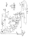
- FIG. 1 shows a schematic arrangement of a milking plant for milking cows. Only two milking parlours are shown by way of illustration, in each of which a cow is present.
- a milking robot 1 having four teat cups 2 at its end.
- the invention is completely independent of the manner in which the teat cups are connected; the teat cups may, combined in one single milking claw, be connected together as well as individually and independently of each other to respective teats of a cow's udder.
- the milk obtained from each udder quarter with the aid of the teat cups 2 can be conveyed through a separate line 3 (see Figure 2) to a milk measuring device 4. From the milk measuring device 4 the milk is conveyed via a circular line 5, to which the discharge lines of the various milk measuring devices in the various milking parlours are connected, to a milk cooling tank 6.
- the milk measuring device 4 comprises four milk meters 7, only one of which is shown in Figure 2.
- Figure 2 furthermore illustrates the basic arrangement of the milking plant, only one teat cup 2 and only one milk meter 7 having been shown in this arrangement for the sake of simplicity.
- the individual discharge lines 8 of the milk meters 7 are coupled to a common discharge line 9 which terminates in the milk cooling tank 6.
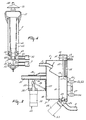
- Figure 3 is a more detailed representation of the basic structure of a milk meter as is incorporated in the milking plant shown in Figure 2.
- the milk meter 7 includes a milk receptacle 10 and a measuring chamber 11, in which connection the milk flows under a vacuum via the separate line 3 connected to the teat cup 2 from the milk receptacle 10 into the measuring chamber 11 and is pumped in defined quantities by means of compressed air from the measuring chamber 11 into the separate discharge line 8.
- the milk meter 7 includes a valve rod 12 which, in a first (shown) position under a vacuum, leaves the aperture 13 between the milk receptacle 10 and the measuring chamber 11 open, and, in a second (non-shown) position by means of compressed air, closes same.
- the milk meter includes a chamber 14, in which chamber the valve rod 12 has a piston 15.
- the valve rod 12 is capable of upward and downward movement in and through this chamber 14.
- the milk meter 7 is connected to a switching element 17 (see Figure 2).
- a vacuum is applied to cause the valve rod 12 and the piston 15 to be moved downwardly to its first position, thereby leaving the aperture 13 open.
- compressed air is admitted into the space below the piston 15 to cause the valve rod 12 and the piston 15 to be moved upwardly to its second position, thereby closing the aperture 13.
- the milk meter 7 furthermore includes a tube 18 which, via relatively narrow apertures 19 and 20, is connected to the space in the chamber 14 below the piston and to the measuring chamber 11, respectively.
- the measuring chamber 11 is provided with a milk level sensor 21, by means of which it is established when a defined quantity of milk is contained therein.
- this sensor 21 supplies a control signal S1 (see Figure 2) to cause the switching element 17 to be adjusted from its first position to its second position, so that the measuring chamber 11 can be emptied.
- S1 control signal
- the switching element 17 is adjusted from its second position to its first position; this period of time is of such a duration that there is sufficient time for the measuring chamber 11 to be emptied.
- the measuring chamber 11 can be filled again.
- the milk level sensor 21 can also apply a control signal S2 to a computer 22, in which the quantity of milk obtained from each udder quarter is recorded for each individual cow.
- a spherical body 23 In the lower part of the measuring chamber 11 there is provided a spherical body 23. When the measuring chamber 11 is empty, this spherical body 23 closes the aperture 24 between the measuring chamber 11 and the separate discharge line 8.
- the spherical body 23 is made of such a material that, when the milk flows from the milk receptacle 10 into the measuring chamber 11, it floats on the milk contained therein. When the milk is forced from the measuring chamber 11 into the separate discharge line 8, the aperture 24 is closed automatically by the spherical body 23 once the measuring chamber 11 is empty.
- a non-return valve 25 is arranged in the separate discharge line 8 beyond the aperture 24 in the measuring chamber, pereferably as closely as possible therebeyond.
- this non-return valve 25 the milk is allowed to pass from the measuring chamber 11 but only under the influence of compressed air.
- the non-return valve 25 blocks any milk flow which might be possible in case, for whatever reason, the pressure in the relevant discharge lines would exceed that prevailing in the measuring chamber 11 in front of the non-return valve 25.
- the milk meter 7 is fitted with a lifting magnet 26 which moves the spherical body 23 upwardly in response to a control signal S3 supplied by the computer 22.
- the milk meter 7 includes a milk conductivity sensor 27, which sensor, preferably, is arranged in the measuring chamber 11.
- the control signal S4 supplied by the milk conductivity sensor 27 is a measure of the health of the udder; in the case of mastitis, the conductivity of the milk is higher than that of the milk obtained from a healthy udder or from a healthy udder quarter.
- the milk originating from an inflamed udder quarter must be separated off.
- the separate discharge line 8 is provided with a three-way valve 28, through which the milk pumped from the milk meter 7 is either passed into the common discharge line 9 or, after it has been found that the milk originates from an inflamed quarter, into a receptacle 29 specially provided for the purpose.
- the three-way valve 28 might be operated automatically as soon as the signal S4 produced by the milk conductivity sensor 27 indicates a value which exceeds a preset value. It is, however, more advantageous to apply the control signal S4 to the computer 22 which, taking account of the further conditions of the specific cow, supplies a control signal S5, by means of which the three-way valve 28 can be operated.
- the milk meter 7 is provided with a tube stop valve 30, with the aid of which the vacuum connection 31 can be disconnected from the milk meter after milking.
- a vacuum prevails in the milk receptacle 10.
- the vacuum Prior to removing the vacuum from the milk receptacle 10, the vacuum line 31 must be closed first. For that purpose, after a milking period preset in the computer 22 has elapsed, a control signal S6 is applied to the electromagnet 32 of the tube stop valve 30.
- a rod 33 having a spherical end 34 is moved upwardly to seal the vacuum connection 31 against the fixed stop 35.
- a lifting mechanism 36 which is connected pivotably to the rod 33, a valve 37 in the wall of the milk receptacle 10 is drawn upwards simultaneously, as a result of which air can flow freely thereinto.
- the milking plant as shown schematically in Figure 2 includes in a customary manner a vacuum pump 38 having a vacuum balance tank 39 to increase the vacuum stability.
- the balance tank 39 has a plurality of vacuum connections.
- a vacuum connection 31 is provided for the milk receptacle 10 of each milk meter 7.
- a vacuum connection 40 is present for each switching element 17.
- a vacuum connection 41 is provided for an electronic pulsator system 42 for the four teat cups.
- a throttle ring 43 to prevent fluctuations in the vacuum of the various milk meters due to falling off of one of the teat cups.
- an air flow sensor 44 in the vacuum connection between the throttle ring 43 and the relevant milk meter, which sensor supplies the computer 22 with a control signal S8 indicating the presence of vacuum in the line 31.
- this signal also forms an indication whether the teat cups are connected correctly.
- FIG. 4 shows a longitudinal cross-sectional view of a teat cup; this teat cup in a customary manner consists of a solid, e.g. metal, sleeve 45, an inner wall 46 made of a flexible material, e.g. rubber, enclosed thereby, and a rubber cap 47 which seals the space between the sleeve 45 and the inner wall 46 at the upper side.
- a sealing ring 48 At the lower side, the space between the sleeve 45 and the inner wall 46 is sealed by a sealing ring 48, while at some distance thereabove there is provided between the sleeve 45 and the inner wall 46 a ring 49 having an aperture 50.
- a space in which the electronic pulsator system 42 produces through the line 52 and via an aperture 51 a pulsating vacuum, thereby effecting in the space between the sleeve 45 and the inner wall 46 a pulsating vacuum which causes the inner wall 46 to close firmly around the teat, when the teat cup is connected thereto, or causes the inner wall to move outwards again, whereby is obtained the rhythmic movement around the teat as required for the milking operation to be performed.
- a buffer space 53 in which a relativaly narrow air suction aperture 54 is made for the milk transport.
- the line 3, intended for the discharge of the milk to the milk meter 7, is connected to this buffer space 53.
- the buffer space 53 contains a fixed element 55, which element partly projects into the aperture between the teat space and the buffer space 53 to ensure that the milk flows gradually into the buffer space 53 and a splitting of the milk is prevented.
- a sensor can be provided to perform a temperature measurement.
- the temperature of the milk indicates the body temperature of the cows to be milked; the latter temperature is higher than normally with cows in heat and with sick cows.
- a rinse line system which is constituted by a rinse fluid container 56 having a valve 57, a first rinse line 58, a rinse jetter 59 which can be fitted around the end of the teat cup 2 in a fluid-tight manner, the teat cup 2, the line 3, the milk meter 7, the separate discharge line 8, the common discharge line 9, a three-way valve 60 incorporated therein and a second rinse line 61.
- the three-way valve 60 admits milk from the common discharge line 9 into the circular line 5, and, in its second position, rinse fluid from the common line 9 into the second rinse line 61.
- a rinse command can be delivered by the computer 22 which, to that end, applies a control signal S7 to the three-way valve 60 to adjust same to the appropriate position.
- the discharge lines Prior to starting the rinsing step after the milking operation has ended, the discharge lines must first be freed from milk. This is effected by passing compressed air through the measuring chamber 11, as a result of which the spherical body 23 is pushed upwardly and the aperture 24 is released.
- an air-milk sensor 62 which sensor applies a control signal S9 to the computer, on the basis of which control signal the computer can establish when there is no longer any milk present in the common line - compressed air then passing the air-milk sensor 62 instead of milk - so that the valve 60 can be adjusted for the rinsing procedure.
- the rinse fluid is sucked from the rinse fluid container 56 through the first rinse line 58, the rinse jetter 59, the teat cup 2 and the line 3 to the milk receptacle 10, from where it flows into the measuring chamber 11, whereafter it is pumped therefrom in the same manner as the milk and is fed back via the separate discharge line 8, the common discharge line 9, the three-way valve 60 and the second rinse line 61 to the rinse fluid container 56.
- the milk cooling tank 6 is incorporated in the circular line 5, to which via relevant three-way valves 60 the common discharge lines of the individual milk meters 7 are connected.
- a pump 64 is incorporated in the circular line 5. This pump can operate at at least two different speeds.
- the milk is circulated at a relatively low speed from the milk cooling tank 6 through the circular line 5.
- the circular line 5 is thermally insulated.
- the milk cooling tank 6 is emptied a few times a week, whereafter it can be rinsed.
- a rinsing fluid can be introduced into the milk cooling tank 6 via a valve 65 and a spray nozzle 66.
- the spray nozzle 66 When the spray nozzle 66 is arranged capably of moving, it can cover the entire inner surface of the milk cooling tank 6.
- the rinsing fluid is circulated by the pump in the circular line at a relatively high speed and is ultimately discharged via a three-way valve 67.
- the valves 65, 67, the spray nozzle 66 and the pump 64 can be controlled from the computer 22.
Landscapes
- Life Sciences & Earth Sciences (AREA)
- Animal Husbandry (AREA)
- Environmental Sciences (AREA)
- Physics & Mathematics (AREA)
- Fluid Mechanics (AREA)
- General Physics & Mathematics (AREA)
- Dairy Products (AREA)
- External Artificial Organs (AREA)
- Medicines Containing Plant Substances (AREA)
- Measuring Volume Flow (AREA)
- Separation Using Semi-Permeable Membranes (AREA)
- Treatment Of Water By Ion Exchange (AREA)
- Sampling And Sample Adjustment (AREA)
- Application Of Or Painting With Fluid Materials (AREA)
- Cleaning By Liquid Or Steam (AREA)
- Feeding And Watering For Cattle Raising And Animal Husbandry (AREA)
Abstract
Description
- The present invention relates to a milking plant for milking cows, which plant includes a milk cooling tank. As customary, milk from a cow's udder obtained by means of teat cups is, via a milk measuring device, supplied to the milk cooling tank. Specifically when the milking plant is provided with two or more milking machines, it is advantageously that, according to the invention, the milk cooling tank is included in a circular line, to which the discharge line of a milk measuring device is connected. When the connection of this discharge line with the circular line can be blocked, e.g. by a valve, the circular line as well as the conducts of the several milking machines all form separate conduct systems. In order to keep the milk in motion in the circular line and to prevent milk residues from being deposited therein, a pump may be provided for circulating the milk from the milk cooling tank therethrough. To minimize temperature losses thereby, the circular line is preferably thermally insulated.
- Usually the milk cooling tank is emptied a few times a week, whereafter it can be rinsed. In accordance with the invention, the milk cooling tank may be provided with a rinsing fluid supply line, through which, after all the milk has been removed from the milk cooling tank, a rinsing fluid can be admitted into the milk cooling tank, which rinsing fluid is circulated through the circular line by means of said pump. As the milk in the circular line only must be kept in motion, the pump may operate at two speeds, the milk being circulated at a relatively low speed and the rinsing fluid at a relatively high speed. The milk cooling tank may be provided with a first valve, via which a rinsing fluid is introduced into the milk cooling tank, while a second valve may be incorporated in the circular line, by means of which the circulating rinsing fluid is discharged.
- When the milking process has to be automated, in accordance with the invention, a milking robot will be provided for automatically connecting the teat cups to the respective teats of a cow's udder. The milking robot will be controlled by a computer. This computer may also be used to control the first and second valve as well as the pump.
- For a better understanding of the invention and to show how the same may be carried into effect, reference will now be made, by way of example, to the accompanying drawings, in which:
- Figure 1 shows schematically an arrangement of a milking plant for milking cows;
- Figure 2 shows a basic arrangement of the milking plant in accordance with the invention;
- Figure 3 is a more detailed representation of the basic structure of a milk meter in the arrangement shown in Figure 2, and
- Figure 4 is a more detailed representation of the basic structure of a teat cup in the arrangement shown in Figure 2.
- Corresponding components in the drawings have been denoted by the same reference numerals.
- Figure 1 shows a schematic arrangement of a milking plant for milking cows. Only two milking parlours are shown by way of illustration, in each of which a cow is present. For each milking parlour there is provided a milking robot 1 having four
teat cups 2 at its end. For the matter of that, the invention is completely independent of the manner in which the teat cups are connected; the teat cups may, combined in one single milking claw, be connected together as well as individually and independently of each other to respective teats of a cow's udder. The milk obtained from each udder quarter with the aid of theteat cups 2 can be conveyed through a separate line 3 (see Figure 2) to a milk measuring device 4. From the milk measuring device 4 the milk is conveyed via a circular line 5, to which the discharge lines of the various milk measuring devices in the various milking parlours are connected, to amilk cooling tank 6. - The milk measuring device 4 comprises four milk meters 7, only one of which is shown in Figure 2. Figure 2 furthermore illustrates the basic arrangement of the milking plant, only one
teat cup 2 and only one milk meter 7 having been shown in this arrangement for the sake of simplicity. Theindividual discharge lines 8 of the milk meters 7 are coupled to a common discharge line 9 which terminates in themilk cooling tank 6. Figure 3 is a more detailed representation of the basic structure of a milk meter as is incorporated in the milking plant shown in Figure 2. The milk meter 7 includes amilk receptacle 10 and a measuring chamber 11, in which connection the milk flows under a vacuum via the separate line 3 connected to theteat cup 2 from themilk receptacle 10 into the measuring chamber 11 and is pumped in defined quantities by means of compressed air from the measuring chamber 11 into theseparate discharge line 8. The milk meter 7 includes avalve rod 12 which, in a first (shown) position under a vacuum, leaves theaperture 13 between themilk receptacle 10 and the measuring chamber 11 open, and, in a second (non-shown) position by means of compressed air, closes same. At its upper side, the milk meter includes achamber 14, in which chamber thevalve rod 12 has apiston 15. Thevalve rod 12 is capable of upward and downward movement in and through thischamber 14. In the space below thepiston 15 there is provided in the wall of thechamber 14 anaperture 16. Via thisaperture 16, the milk meter 7 is connected to a switching element 17 (see Figure 2). In a first position of thisswitching element 17, a vacuum is applied to cause thevalve rod 12 and thepiston 15 to be moved downwardly to its first position, thereby leaving theaperture 13 open. In a second position of thisswitching element 17, compressed air is admitted into the space below thepiston 15 to cause thevalve rod 12 and thepiston 15 to be moved upwardly to its second position, thereby closing theaperture 13. The milk meter 7 furthermore includes a tube 18 which, via relativelynarrow apertures chamber 14 below the piston and to the measuring chamber 11, respectively. When compressed air is admitted into the space below thepiston 15, theaperture 13 is closed immediately and the air is forced into the measuring chamber 11 via theaperture 19, the tube 18 and theaperture 20, as a result of which the milk present in the measuring chamber 11 is passed into theseparate discharge line 8. - The measuring chamber 11 is provided with a milk level sensor 21, by means of which it is established when a defined quantity of milk is contained therein. When the milk level in the measuring chamber 11 has reached that of the sensor 21, this sensor 21 supplies a control signal S1 (see Figure 2) to cause the
switching element 17 to be adjusted from its first position to its second position, so that the measuring chamber 11 can be emptied. After a fixed period of time, theswitching element 17 is adjusted from its second position to its first position; this period of time is of such a duration that there is sufficient time for the measuring chamber 11 to be emptied. When theswitching element 17 has returned to its first position, the measuring chamber 11 can be filled again. The milk level sensor 21 can also apply a control signal S2 to acomputer 22, in which the quantity of milk obtained from each udder quarter is recorded for each individual cow. - In the lower part of the measuring chamber 11 there is provided a
spherical body 23. When the measuring chamber 11 is empty, thisspherical body 23 closes theaperture 24 between the measuring chamber 11 and theseparate discharge line 8. Thespherical body 23 is made of such a material that, when the milk flows from themilk receptacle 10 into the measuring chamber 11, it floats on the milk contained therein. When the milk is forced from the measuring chamber 11 into theseparate discharge line 8, theaperture 24 is closed automatically by thespherical body 23 once the measuring chamber 11 is empty. A non-return valve 25 is arranged in theseparate discharge line 8 beyond theaperture 24 in the measuring chamber, pereferably as closely as possible therebeyond. Via this non-return valve 25 the milk is allowed to pass from the measuring chamber 11 but only under the influence of compressed air. In the opposite direction, the non-return valve 25 blocks any milk flow which might be possible in case, for whatever reason, the pressure in the relevant discharge lines would exceed that prevailing in the measuring chamber 11 in front of the non-return valve 25. When, during the milking operation, the first obtained milk flows into the measuring chamber 11, then not only the measuring chamber 11 itself will be filled, but also the space in theseparate discharge line 8 between the non-return valve 25 and the saidaperture 24. By each subsequent pump stroke it is only the milk contained in the measuring chamber that is pumped off, so that the total quantity of milk as determined by the computer during milking for each udder quarter must be increased only once by the quantity of milk corresponding to the volume of theseparate discharge line 8 between the non-return valve 25 and the saidaperture 24. This is, however, a constant correction to be entered into thecomputer 22 on recording of the quantity of milk obtained. After milking, the milk must also be forced from theseparate discharge lines 8 and the common discharge line 9, i.e. into the circular line 5 to themilk cooling tank 6. For that purpose, theaperture 23 in the measuring chamber 11 must be free so as to allow compressed air to pass. To that end, the milk meter 7 is fitted with alifting magnet 26 which moves thespherical body 23 upwardly in response to a control signal S3 supplied by thecomputer 22. - The milk meter 7 includes a
milk conductivity sensor 27, which sensor, preferably, is arranged in the measuring chamber 11. The control signal S4 supplied by themilk conductivity sensor 27 is a measure of the health of the udder; in the case of mastitis, the conductivity of the milk is higher than that of the milk obtained from a healthy udder or from a healthy udder quarter. The milk originating from an inflamed udder quarter must be separated off. For this purpose, theseparate discharge line 8 is provided with a three-way valve 28, through which the milk pumped from the milk meter 7 is either passed into the common discharge line 9 or, after it has been found that the milk originates from an inflamed quarter, into areceptacle 29 specially provided for the purpose. The three-way valve 28 might be operated automatically as soon as the signal S4 produced by themilk conductivity sensor 27 indicates a value which exceeds a preset value. It is, however, more advantageous to apply the control signal S4 to thecomputer 22 which, taking account of the further conditions of the specific cow, supplies a control signal S5, by means of which the three-way valve 28 can be operated. - In addition, the milk meter 7 is provided with a
tube stop valve 30, with the aid of which thevacuum connection 31 can be disconnected from the milk meter after milking. During milking, a vacuum prevails in themilk receptacle 10. After the milking procedure has ended, the vacuum must be removed, and it is not until then that the teat cups are removed from the teats. Prior to removing the vacuum from themilk receptacle 10, thevacuum line 31 must be closed first. For that purpose, after a milking period preset in thecomputer 22 has elapsed, a control signal S6 is applied to theelectromagnet 32 of thetube stop valve 30. By means of the then energizedelectromagnet 32, arod 33 having aspherical end 34 is moved upwardly to seal thevacuum connection 31 against the fixedstop 35. With the aid of alifting mechanism 36 which is connected pivotably to therod 33, avalve 37 in the wall of themilk receptacle 10 is drawn upwards simultaneously, as a result of which air can flow freely thereinto. - The milking plant as shown schematically in Figure 2 includes in a customary manner a
vacuum pump 38 having avacuum balance tank 39 to increase the vacuum stability. Thebalance tank 39 has a plurality of vacuum connections. Avacuum connection 31 is provided for themilk receptacle 10 of each milk meter 7. A vacuum connection 40 is present for each switchingelement 17. In addition, a vacuum connection 41 is provided for an electronic pulsator system 42 for the four teat cups. In thevacuum connection 31 there is incorporated a throttle ring 43 to prevent fluctuations in the vacuum of the various milk meters due to falling off of one of the teat cups. In order to be able to ascertain whether a vacuum is present in the milk meter, there is arranged an air flow sensor 44 in the vacuum connection between the throttle ring 43 and the relevant milk meter, which sensor supplies thecomputer 22 with a control signal S8 indicating the presence of vacuum in theline 31. Hereby this signal also forms an indication whether the teat cups are connected correctly. - Figure 4 shows a longitudinal cross-sectional view of a teat cup; this teat cup in a customary manner consists of a solid, e.g. metal, sleeve 45, an inner wall 46 made of a flexible material, e.g. rubber, enclosed thereby, and a rubber cap 47 which seals the space between the sleeve 45 and the inner wall 46 at the upper side. At the lower side, the space between the sleeve 45 and the inner wall 46 is sealed by a sealing ring 48, while at some distance thereabove there is provided between the sleeve 45 and the inner wall 46 a
ring 49 having anaperture 50. Between the sealing ring 48 and thering 49 there is located a space, in which the electronic pulsator system 42 produces through theline 52 and via an aperture 51 a pulsating vacuum, thereby effecting in the space between the sleeve 45 and the inner wall 46 a pulsating vacuum which causes the inner wall 46 to close firmly around the teat, when the teat cup is connected thereto, or causes the inner wall to move outwards again, whereby is obtained the rhythmic movement around the teat as required for the milking operation to be performed. In order to function as a buffer for the milk to be collected and to minimize the fluctuations in the vacuum under the teat, there is provided in the lower part of the teat cup 2 abuffer space 53, in which a relativaly narrowair suction aperture 54 is made for the milk transport. The line 3, intended for the discharge of the milk to the milk meter 7, is connected to thisbuffer space 53. In addition, thebuffer space 53 contains a fixedelement 55, which element partly projects into the aperture between the teat space and thebuffer space 53 to ensure that the milk flows gradually into thebuffer space 53 and a splitting of the milk is prevented. At the upper end of the fixed element 55 a sensor can be provided to perform a temperature measurement. The temperature of the milk indicates the body temperature of the cows to be milked; the latter temperature is higher than normally with cows in heat and with sick cows. - In order that the milk line system can be rinsed once the milking operation has been completed, it must include an arrangement for effecting this step. To that end, there is provided a rinse line system which is constituted by a rinse
fluid container 56 having avalve 57, a first rinseline 58, a rinsejetter 59 which can be fitted around the end of theteat cup 2 in a fluid-tight manner, theteat cup 2, the line 3, the milk meter 7, theseparate discharge line 8, the common discharge line 9, a three-way valve 60 incorporated therein and a second rinseline 61. In its first position, the three-way valve 60 admits milk from the common discharge line 9 into the circular line 5, and, in its second position, rinse fluid from the common line 9 into the second rinseline 61. After the milking, a rinse command can be delivered by thecomputer 22 which, to that end, applies a control signal S7 to the three-way valve 60 to adjust same to the appropriate position. Prior to starting the rinsing step after the milking operation has ended, the discharge lines must first be freed from milk. This is effected by passing compressed air through the measuring chamber 11, as a result of which thespherical body 23 is pushed upwardly and theaperture 24 is released. In front of the three-way valve 60 there is incorporated in the common discharge line 9 an air-milk sensor 62, which sensor applies a control signal S9 to the computer, on the basis of which control signal the computer can establish when there is no longer any milk present in the common line - compressed air then passing the air-milk sensor 62 instead of milk - so that thevalve 60 can be adjusted for the rinsing procedure. Due to the vacuum in themilk receptacle 10, the rinse fluid is sucked from the rinsefluid container 56 through the first rinseline 58, the rinsejetter 59, theteat cup 2 and the line 3 to themilk receptacle 10, from where it flows into the measuring chamber 11, whereafter it is pumped therefrom in the same manner as the milk and is fed back via theseparate discharge line 8, the common discharge line 9, the three-way valve 60 and the second rinseline 61 to the rinsefluid container 56. - In the common discharge line 9 there is arranged in front of the three-
way valve 60 incorporated therein aheat exchanger 63 as a pre-cooler for the milk cooling tank. - The
milk cooling tank 6 is incorporated in the circular line 5, to which via relevant three-way valves 60 the common discharge lines of the individual milk meters 7 are connected. Apump 64 is incorporated in the circular line 5. This pump can operate at at least two different speeds. In order to keep the milk in motion and to prevent milk residues from being deposited in the circular line 5, the milk is circulated at a relatively low speed from themilk cooling tank 6 through the circular line 5. Preferably, in this connection, the circular line 5 is thermally insulated. Usually, themilk cooling tank 6 is emptied a few times a week, whereafter it can be rinsed. A rinsing fluid can be introduced into themilk cooling tank 6 via avalve 65 and a spray nozzle 66. When the spray nozzle 66 is arranged capably of moving, it can cover the entire inner surface of themilk cooling tank 6. The rinsing fluid is circulated by the pump in the circular line at a relatively high speed and is ultimately discharged via a three-way valve 67. Also here, thevalves pump 64 can be controlled from thecomputer 22. - Although in Figure 2 they are shown as being single, several elements are provided in fourfold; in particular this holds for the rinse jetter, the teat cup and the milk meter, as well as for the lines connected thereto and the elements incorporated therein (valves and sensors). Preferably, the four milk meters are combined into one single milk measuring device.
Claims (8)
- A milking plant for milking cows, which plant includes a milk cooling tank (6), characterized in that the milk cooling tank (6) is included in a circular line (5), to which the discharge line (9) of a milk measuring device (4) is connected.
- A milking plant as claimed in claim 1, characterized in that the circular line (5) is provided with a pump (64) for circulating the milk from the milk cooling tank (6) therethrough.
- A milking plant as claimed in claim 1 or 2, characterized in that the circular line (5) is thermally insulated.
- A milking plant as claimed in any one of the preceding claim, characterized in that the milk cooling tank (6) is provided with a rinsing fluid supply line, through which, after all the milk has been removed from the milk cooling tank (6), a rinsing fluid can be admitted into the milk cooling tank (6), which rinsing fluid is circulated through the circular line (5) by means of the pump (64).
- A milking plant as claimed in claim 4, characterized in that the pump (64) can operate at two speeds, the milk being circulated at a relatively low speed and the rinsing fluid at a relatively high speed.
- A milking plant as claimed in claim 4 or 5, characterized in that the milk cooling tank (6) is provided with a first valve (65), via which a rinsing fluid is introduced into the milk cooling tank (6) and a second valve (67) is incorporated in the circular line (5), by means of which the circulating rinsing fluid can be discharged.
- A milking plant as claimed in claim 6, characterized in that a computer (22) is provided by means of which the first and second valve (65, 67) as well as the pump (64) are controlled.
- A milking plant as claimed in any one of the preceding claims, characterized in that a milking robot (1) is provided for automatically connecting the teat cups (2) to the respective teats of a cow's udder.
Applications Claiming Priority (3)
| Application Number | Priority Date | Filing Date | Title |
|---|---|---|---|
| NL8900479 | 1989-02-27 | ||
| NL8900479A NL193553C (en) | 1989-02-27 | 1989-02-27 | Milking installation. |
| EP90200422A EP0385539B2 (en) | 1989-02-27 | 1990-02-23 | A milking plant |
Related Parent Applications (2)
| Application Number | Title | Priority Date | Filing Date |
|---|---|---|---|
| EP90200422.5 Division | 1990-02-23 | ||
| EP90200422A Division EP0385539B2 (en) | 1989-02-27 | 1990-02-23 | A milking plant |
Publications (4)
| Publication Number | Publication Date |
|---|---|
| EP0511722A2 true EP0511722A2 (en) | 1992-11-04 |
| EP0511722A3 EP0511722A3 (en) | 1993-03-03 |
| EP0511722B1 EP0511722B1 (en) | 1995-01-25 |
| EP0511722B2 EP0511722B2 (en) | 2004-09-15 |
Family
ID=19854213
Family Applications (6)
| Application Number | Title | Priority Date | Filing Date |
|---|---|---|---|
| EP90200422A Expired - Lifetime EP0385539B2 (en) | 1989-02-27 | 1990-02-23 | A milking plant |
| EP92202244A Expired - Lifetime EP0511722B2 (en) | 1989-02-27 | 1990-02-23 | A milking plant |
| EP92202243A Expired - Lifetime EP0516246B2 (en) | 1989-02-27 | 1990-02-23 | A milking plant |
| EP92202259A Revoked EP0510779B1 (en) | 1989-02-27 | 1990-02-23 | A milking plant |
| EP92202258A Expired - Lifetime EP0511723B2 (en) | 1989-02-27 | 1990-02-23 | A milking plant |
| EP19930202990 Withdrawn EP0584890A3 (en) | 1989-02-27 | 1990-02-23 | A milking plant |
Family Applications Before (1)
| Application Number | Title | Priority Date | Filing Date |
|---|---|---|---|
| EP90200422A Expired - Lifetime EP0385539B2 (en) | 1989-02-27 | 1990-02-23 | A milking plant |
Family Applications After (4)
| Application Number | Title | Priority Date | Filing Date |
|---|---|---|---|
| EP92202243A Expired - Lifetime EP0516246B2 (en) | 1989-02-27 | 1990-02-23 | A milking plant |
| EP92202259A Revoked EP0510779B1 (en) | 1989-02-27 | 1990-02-23 | A milking plant |
| EP92202258A Expired - Lifetime EP0511723B2 (en) | 1989-02-27 | 1990-02-23 | A milking plant |
| EP19930202990 Withdrawn EP0584890A3 (en) | 1989-02-27 | 1990-02-23 | A milking plant |
Country Status (6)
| Country | Link |
|---|---|
| US (1) | US5080040A (en) |
| EP (6) | EP0385539B2 (en) |
| AT (5) | ATE116519T1 (en) |
| DE (5) | DE69016461T3 (en) |
| DK (4) | DK0385539T4 (en) |
| NL (4) | NL193553C (en) |
Cited By (26)
| Publication number | Priority date | Publication date | Assignee | Title |
|---|---|---|---|---|
| FR2795815A1 (en) * | 1999-07-01 | 2001-01-05 | Hydro Pulve | Equipment for measuring the rate of flow on a pulveriser nozzle, comprises a container which may be fitted to a nozzle and has upper and lower level sensors connected to a computer with timer |
| EP1205104A2 (en) * | 2000-11-13 | 2002-05-15 | Dec International, Inc. | Milking vacuum fluctuation filter |
| NL1024295C2 (en) * | 2003-09-15 | 2005-03-16 | Lely Entpr Ag | Method for milking an animal and device for this. |
| US8393296B2 (en) | 2011-04-28 | 2013-03-12 | Technologies Holdings Corp. | Milking box with robotic attacher including rotatable gripping portion and nozzle |
| US8590488B2 (en) | 2010-08-31 | 2013-11-26 | Technologies Holdings Corp. | Vision system for facilitating the automated application of disinfectant to the teats of dairy livestock |
| US8671885B2 (en) | 2011-04-28 | 2014-03-18 | Technologies Holdings Corp. | Vision system for robotic attacher |
| US8683946B2 (en) | 2011-04-28 | 2014-04-01 | Technologies Holdings Corp. | System and method of attaching cups to a dairy animal |
| US8746176B2 (en) | 2011-04-28 | 2014-06-10 | Technologies Holdings Corp. | System and method of attaching a cup to a dairy animal according to a sequence |
| US8800487B2 (en) | 2010-08-31 | 2014-08-12 | Technologies Holdings Corp. | System and method for controlling the position of a robot carriage based on the position of a milking stall of an adjacent rotary milking platform |
| US8885891B2 (en) | 2011-04-28 | 2014-11-11 | Technologies Holdings Corp. | System and method for analyzing data captured by a three-dimensional camera |
| US8903129B2 (en) | 2011-04-28 | 2014-12-02 | Technologies Holdings Corp. | System and method for filtering data captured by a 2D camera |
| US9043988B2 (en) | 2011-04-28 | 2015-06-02 | Technologies Holdings Corp. | Milking box with storage area for teat cups |
| US9049843B2 (en) | 2011-04-28 | 2015-06-09 | Technologies Holdings Corp. | Milking box with a robotic attacher having a three-dimensional range of motion |
| US9058657B2 (en) | 2011-04-28 | 2015-06-16 | Technologies Holdings Corp. | System and method for filtering data captured by a 3D camera |
| US9107379B2 (en) | 2011-04-28 | 2015-08-18 | Technologies Holdings Corp. | Arrangement of milking box stalls |
| US9149018B2 (en) | 2010-08-31 | 2015-10-06 | Technologies Holdings Corp. | System and method for determining whether to operate a robot in conjunction with a rotary milking platform based on detection of a milking claw |
| US9161511B2 (en) | 2010-07-06 | 2015-10-20 | Technologies Holdings Corp. | Automated rotary milking system |
| US9161512B2 (en) | 2011-04-28 | 2015-10-20 | Technologies Holdings Corp. | Milking box with robotic attacher comprising an arm that pivots, rotates, and grips |
| US9215861B2 (en) | 2011-04-28 | 2015-12-22 | Technologies Holdings Corp. | Milking box with robotic attacher and backplane for tracking movements of a dairy animal |
| US9258975B2 (en) | 2011-04-28 | 2016-02-16 | Technologies Holdings Corp. | Milking box with robotic attacher and vision system |
| US9265227B2 (en) | 2011-04-28 | 2016-02-23 | Technologies Holdings Corp. | System and method for improved attachment of a cup to a dairy animal |
| US9357744B2 (en) | 2011-04-28 | 2016-06-07 | Technologies Holdings Corp. | Cleaning system for a milking box stall |
| US9681634B2 (en) | 2011-04-28 | 2017-06-20 | Technologies Holdings Corp. | System and method to determine a teat position using edge detection in rear images of a livestock from two cameras |
| US10111401B2 (en) | 2010-08-31 | 2018-10-30 | Technologies Holdings Corp. | System and method for determining whether to operate a robot in conjunction with a rotary parlor |
| US10127446B2 (en) | 2011-04-28 | 2018-11-13 | Technologies Holdings Corp. | System and method for filtering data captured by a 2D camera |
| US10357015B2 (en) | 2011-04-28 | 2019-07-23 | Technologies Holdings Corp. | Robotic arm with double grabber and method of operation |
Families Citing this family (85)
| Publication number | Priority date | Publication date | Assignee | Title |
|---|---|---|---|---|
| US5275124A (en) * | 1989-02-27 | 1994-01-04 | C. Van Der Lely N.V. | Milking apparatus |
| US5272997A (en) * | 1989-02-27 | 1993-12-28 | C. Van Der Lely N.V. | Milking apparatus |
| NL9101636A (en) * | 1991-09-27 | 1993-04-16 | Lely Nv C Van Der | METHOD FOR AUTOMATIC MILKING OF ANIMALS. |
| US5568788A (en) * | 1990-02-27 | 1996-10-29 | C. Van Der Lely N.V. | Implement for and a method of milking animals automatically |
| FR2676187B1 (en) * | 1991-05-06 | 1995-03-31 | Seli Hugonnet | DEVICE AND METHOD FOR WASHING A MILK PRESERVATION TANK. |
| NL9200258A (en) * | 1991-10-04 | 1993-05-03 | Lely Nv C Van Der | METHOD FOR CLEANING MILK BEAKERS AND / OR AFTER-TREATMENT OF THE WEANING OF A MILKED ANIMAL, ANIMAL MILKING APPARATUS FOR USING THIS METHOD (S), AND A RINSE TOOL APPLIED IN SUCH AN APPARATUS. |
| ES2157894T3 (en) * | 1991-11-22 | 2001-09-01 | Berthold Johannes The Dietrich | DEVICE FOR PNEUMATIC MILK AND PEZONERA FOR THIS DEVICE. |
| NL9200091A (en) * | 1992-01-17 | 1993-08-16 | Lely Nv C Van Der | MILK MACHINE. |
| NL9200582A (en) * | 1992-03-30 | 1993-10-18 | Lely Nv C Van Der | METHOD AND APPARATUS FOR AUTOMATIC MILKING OF ANIMALS. |
| AU664282B2 (en) * | 1992-06-25 | 1995-11-09 | Lely Patent N.V. | A construction for automatically milking animals, such as cows |
| DE69231064T2 (en) * | 1992-10-09 | 2000-09-28 | Tickleford Ltd | DEVICE FOR MILKING AN ANIMAL |
| NL9300143A (en) * | 1993-01-26 | 1994-08-16 | Lely Nv C Van Der | Milking machine. |
| NL9300578A (en) * | 1993-04-01 | 1994-11-01 | Texas Industries Inc | Device for automatic milking of animals. |
| NL9300918A (en) * | 1993-05-28 | 1994-12-16 | Lely Nv C Van Der | Device for milking animals. |
| NL9300917A (en) * | 1993-05-28 | 1994-12-16 | Lely Nv C Van Der | Device for milking animals. |
| NL9300997A (en) * | 1993-06-10 | 1995-01-02 | Lely Nv C Van Der | A method for milking animals, as well as a device for applying this method. |
| US5572946A (en) * | 1993-08-10 | 1996-11-12 | R J Fullwood And Bland Limited | Milking sampling for diagnostic purposes |
| NL9301985A (en) * | 1993-11-17 | 1995-06-16 | Texas Industries Inc | Milking machine. |
| JPH08511171A (en) * | 1994-03-25 | 1996-11-26 | マースランド エヌ・ヴィ | Structure containing animal milking equipment |
| NL9500362A (en) * | 1994-04-14 | 1995-11-01 | Maasland Nv | Method for automatic milking of animals and device in which this method can be applied. |
| NL9401937A (en) * | 1994-04-27 | 1995-12-01 | Maasland Nv | Method for automatic milking of animals and device in which this method can be applied. |
| SE9401684D0 (en) * | 1994-05-17 | 1994-05-17 | Tetra Laval Holdings & Finance | Method of milking animals |
| SE9401685D0 (en) * | 1994-05-17 | 1994-05-17 | Tetra Laval Holdings & Finance | Method of milking animals |
| NL9500347A (en) * | 1994-05-19 | 1996-01-02 | Maasland Nv | Construction with device for milking animals and method for cleaning teat cups. |
| NL9402010A (en) * | 1994-11-30 | 1996-07-01 | Maasland Nv | Device for milking animals. |
| EP1138193B1 (en) * | 1994-12-09 | 2004-08-18 | Maasland N.V. | An implement for milking animals |
| DE69624152T2 (en) | 1995-02-15 | 2003-11-06 | Maasland Nv | Device for milking animals |
| SE504429C2 (en) * | 1995-05-17 | 1997-02-10 | Tetra Laval Holdings & Finance | Ways to control milking using the abrupt movement of teat rubber and milking machine with sensors for this |
| SE504427C2 (en) * | 1995-05-17 | 1997-02-10 | Tetra Laval Holdings & Finance | Method and apparatus for milking an animal by determining the level of the pulsation vacuum when the teat rubber opens or closes abruptly |
| DE29510414U1 (en) * | 1995-07-03 | 1996-10-31 | Duevelsdorf & Sohn Gmbh & Co K | Milking device |
| NL1001257C2 (en) * | 1995-09-21 | 1997-03-25 | Maasland Nv | Method for determining the amount of milk collected during a milking run. |
| NL1004196C1 (en) * | 1995-11-24 | 1997-05-27 | Maasland Nv | Device for milking animals. |
| EP1169913B1 (en) * | 1996-11-01 | 2004-02-25 | Maasland N.V. | An implement for automatically milking animals |
| US6148766A (en) * | 1996-12-17 | 2000-11-21 | Van Der Lely; Cornelis | Construction including an implement for automatically milking animals |
| US6089242A (en) * | 1998-02-10 | 2000-07-18 | Babson Bros. Co. | Dairy harvesting facility wash system |
| SE9704781D0 (en) * | 1997-12-19 | 1997-12-19 | Alfa Laval Agri Ab | A method and apparatus for separating foremilk |
| US5974345A (en) * | 1998-02-10 | 1999-10-26 | Babson Bros. Co. | Dairy chemical dispensing system |
| US5928934A (en) * | 1998-04-14 | 1999-07-27 | Mccormick; James B. | Apparatus and method for preparing small tissue samples for histological examination |
| SE519708C2 (en) * | 1998-07-31 | 2003-04-01 | Delaval Holding Ab | Device and method for detecting a disease of the udder of an animal |
| SE512852C2 (en) * | 1998-09-04 | 2000-05-22 | Alfa Laval Agri Ab | Teat cup for milking cows or other animals |
| WO2000018218A1 (en) * | 1998-09-28 | 2000-04-06 | Babson Bros. Co. | Milk flow monitor and milker unit detacher |
| EP1126757B8 (en) * | 1998-11-05 | 2003-03-26 | ChemoMetec A/S | A system for regulating the handling of milk during the milking process and a method for regulating said milking process |
| NL1010963C2 (en) * | 1999-01-06 | 2000-07-07 | Lely Research Holding Ag | Vacuum control system. |
| DE19900274B4 (en) * | 1999-01-07 | 2009-01-29 | Werner Happel | Method for adapting the milking installation to a herd of animals |
| IT1312326B1 (en) * | 1999-05-26 | 2002-04-15 | Consiglio Nazionale Ricerche | MECHANICAL DEVICE FOR THE AUTOMATIC ATTACHMENT OF THE NIPPICKS IN A ROBOTIC MILKING STATION. |
| SE515217C2 (en) * | 1999-09-15 | 2001-07-02 | Delaval Holding Ab | Apparatus for automatic milking of animals |
| SE9904065L (en) * | 1999-11-10 | 2001-05-11 | Delaval Holding Ab | Device for improved milking |
| SE515443C3 (en) | 1999-12-15 | 2001-08-14 | Delaval Holding Ab | Method and apparatus for teat cup washing |
| SE0000362D0 (en) * | 2000-02-04 | 2000-02-04 | Alfa Laval Agri Ab | Method and system for controlled cooling of small milk quantities |
| NZ523120A (en) * | 2000-05-12 | 2004-05-28 | Innovative Agricultural Produc | Volumetric liquid metering device |
| NL1016834C2 (en) * | 2000-12-08 | 2002-06-11 | Nedap Nv | Identification or verification of an identity based on a milk flow profile. |
| SE521033C2 (en) * | 2001-01-12 | 2003-09-23 | Delaval Holding Ab | Method and apparatus for automatically milking animals and computer programs for this |
| SE520278C2 (en) | 2001-09-20 | 2003-06-17 | Delaval Holding Ab | Arrangement and procedure for milking animals |
| NL1019062C2 (en) * | 2001-09-28 | 2003-04-02 | Lely Entpr Ag | Device for milking animals. |
| NL1020785C2 (en) * | 2002-06-06 | 2003-12-09 | Lely Entpr Ag | Device for milking animals. |
| NL1020784C2 (en) * | 2002-06-06 | 2003-12-09 | Lely Entpr Ag | Device for automatically milking an animal. |
| NZ519464A (en) * | 2002-06-10 | 2005-01-28 | Radian Technology Ltd | A method and an apparatus for improving measurement sensitivity of a parameter of a fluid |
| SE523800C2 (en) * | 2002-09-30 | 2004-05-18 | Delaval Holding Ab | Method for calibrating milk meters in a milking system |
| SE0203006D0 (en) * | 2002-10-11 | 2002-10-11 | Delaval Holding Ab | A milking plant |
| EP1443324A1 (en) | 2003-01-31 | 2004-08-04 | DeLaval Holding AB | Milk metering apparatus and method of milking an animal |
| US6736087B1 (en) * | 2003-06-02 | 2004-05-18 | Martin Dionne | Milk sampler |
| SE527517C2 (en) * | 2003-06-30 | 2006-03-28 | Delaval Holding Ab | Remote control of automatic milking system |
| US8540821B2 (en) | 2004-03-26 | 2013-09-24 | Maasland N.V. | Teat cup cleaning device and method |
| SE527747C2 (en) * | 2004-09-14 | 2006-05-30 | Delaval Holding Ab | Teat cup and teat cup part |
| US7699024B2 (en) * | 2006-09-20 | 2010-04-20 | Rysewyk Terry P | Milk temperature monitor with ambient temperature compensation |
| DE102008015321A1 (en) * | 2007-03-22 | 2008-12-04 | Westfaliasurge Gmbh | Device for milking animals comprises a control unit, milking containers, collecting units for collecting milk and a milk line for transporting the milk |
| US20100282173A1 (en) * | 2008-01-02 | 2010-11-11 | Delaval Holding Ab | Method and device for controlling the milking by a milking machine |
| NL1035972C (en) * | 2008-09-24 | 2010-03-25 | Lely Patent Nv | DEVICE FOR MILKING ANIMALS. |
| CL2009000437A1 (en) | 2009-02-26 | 2009-09-04 | Valenzuela Ronnie Uslar | Automatic independent liner removal system which, when incorporated into any conventional milking equipment, automatically discriminates when the milk contained in each mammary glandular room is finished, comprises in each short hose each nipple is a discrete and empty flow sensor, interconnected to a controller. |
| WO2010142301A1 (en) * | 2009-06-09 | 2010-12-16 | Tartu Ülikool (University Of Tartu) | Method for the detection of mastitis and milk quality, and mastitis sensor |
| US9545077B2 (en) | 2011-12-16 | 2017-01-17 | Delaval Holding Ab | Milking system and a method for preventing detachment of a teat cup from a teat during a milking process |
| JP6103779B2 (en) | 2011-12-22 | 2017-03-29 | デラヴァル ホルディング アーベー | Coupler and nipple cup |
| ES2627989T3 (en) | 2011-12-22 | 2017-08-01 | Delaval Holding Ab | A cartridge and a teat cup |
| DE102012110503A1 (en) * | 2012-03-14 | 2013-09-19 | Gea Farm Technologies Gmbh | Divider of a milking parlor arrangement and milking parlor arrangement |
| DE212013000165U1 (en) * | 2012-07-25 | 2015-02-25 | Scr Engineers, Ltd. | milking system |
| EP2991474B1 (en) | 2013-05-02 | 2019-08-21 | DeLaval Holding AB | A cartridge, and a teat cup |
| US20150296736A1 (en) * | 2014-04-17 | 2015-10-22 | Milkline Srl | Method implemented by a computer for the control of milking operations on automated systems |
| NL2012793B1 (en) * | 2014-05-09 | 2016-02-24 | Lely Patent Nv | Milk system. |
| NL2015620B1 (en) * | 2015-10-15 | 2017-05-08 | N V Nederlandsche Apparatenfabriek Nedap | Milk meter. |
| US10798911B2 (en) * | 2016-12-01 | 2020-10-13 | Delaval Holding Ab | Milking arrangement, and a method of operating a milking arrangement |
| NL2017992B1 (en) * | 2016-12-14 | 2018-06-26 | Lely Patent Nv | Milk system |
| NL2017995B1 (en) * | 2016-12-14 | 2018-06-26 | Lely Patent Nv | Milk system |
| EP3610900A1 (en) * | 2018-08-16 | 2020-02-19 | Medela Holding AG | Baby bottle with bottle attachment |
| NL2021685B1 (en) * | 2018-09-24 | 2020-05-07 | Lely Patent Nv | Milking system with detection system |
| CN109845646A (en) * | 2018-12-29 | 2019-06-07 | 于飞 | A kind of high-quality yak milk milker and milking method |
Citations (4)
| Publication number | Priority date | Publication date | Assignee | Title |
|---|---|---|---|---|
| DE1868110U (en) * | 1962-12-14 | 1963-02-28 | Christensen & Co As S A | MILKING DEVICE. |
| DE7325950U (en) * | 1973-07-14 | 1973-11-22 | Alfa-Laval Bergedorfer Eisenwerke Gmbh | Device for cooling freshly milked milk |
| FR2272595A1 (en) * | 1974-05-27 | 1975-12-26 | Kirwan Patrick | |
| US4175514A (en) * | 1977-05-19 | 1979-11-27 | Frank F. Souza, Inc. | Automatic milking machine control and cleansing |
Family Cites Families (46)
| Publication number | Priority date | Publication date | Assignee | Title |
|---|---|---|---|---|
| DD41115A (en) * | ||||
| US2737923A (en) * | 1951-02-13 | 1956-03-13 | Zero Mfg Company | Vacuum and pulsator equipment for use with the milking of farm animals |
| US2703067A (en) * | 1951-05-05 | 1955-03-01 | Frederick L Carlson | Quarter milker |
| US2873723A (en) * | 1957-04-26 | 1959-02-17 | Zero Mfg Company | Vacuum bulk milk tank with agitators |
| US2873722A (en) * | 1957-11-22 | 1959-02-17 | Zero Mfg Company | Bulk milk tank and washer therefor |
| US3036552A (en) * | 1960-09-16 | 1962-05-29 | Zero Mfg Company | Bulk milk tank system and control therefor |
| US3373720A (en) * | 1964-09-22 | 1968-03-19 | Zero Mfg Company | Milking unit and process |
| US3289633A (en) * | 1965-06-24 | 1966-12-06 | Sta Rite Products Inc | Bucket for milking apparatus |
| US3538768A (en) * | 1967-11-13 | 1970-11-10 | Zero Manufacturing Co | Milk measuring device |
| US3586043A (en) * | 1969-08-14 | 1971-06-22 | Zero Manufacturing Co | Milking apparatus with dual valve |
| NL7014273A (en) * | 1969-10-06 | 1971-04-08 | ||
| US3837318A (en) * | 1970-10-12 | 1974-09-24 | Zero Manufacturing Co | Automatic milker release |
| US3754532A (en) * | 1971-06-09 | 1973-08-28 | Alfa Laval Ab | Milking machine |
| US3874337A (en) * | 1973-07-30 | 1975-04-01 | Raymond E Umbaugh | Temperature responsive system for milking apparatus |
| US3919975A (en) * | 1974-08-05 | 1975-11-18 | Lloyd P Duncan | Milker unit |
| CS183854B1 (en) * | 1975-04-29 | 1978-07-31 | Ladislav Mukarovsky | Equipment for automatic checking and control of milking process |
| US4034712A (en) * | 1975-11-24 | 1977-07-12 | Duncan Lloyd P | Pulsation system |
| US4011838A (en) * | 1976-03-25 | 1977-03-15 | Alfa-Laval Ab | Electronic milker |
| SE406028B (en) * | 1976-05-21 | 1979-01-22 | Alfa Laval Ab | DEVICE FOR DISHING A TUB MILKING SYSTEM |
| DE2759126A1 (en) * | 1977-12-30 | 1979-07-12 | Mezoegazdasagi Foeiskola | Milking procedure to obtain blood-free, sterile milk - involves diversion of milk flow into adjacent container for short period after start f milking (HU 28.11.77) |
| DE2810376B2 (en) * | 1978-03-10 | 1980-04-03 | D E C Gmbh, 4660 Gelsenkirchen-Buer | Milk meter |
| US4344385A (en) * | 1978-05-03 | 1982-08-17 | Babson Bros. Co. | Milker |
| WO1981001612A1 (en) * | 1979-11-26 | 1981-06-11 | Adit Invent Ab | Device for measuring temperature changes in animals |
| US4287853A (en) * | 1980-03-24 | 1981-09-08 | Duncan Lloyd P | Milking device |
| US4351271A (en) * | 1980-09-04 | 1982-09-28 | Paul Mueller Company | Refrigerated receiver |
| JPS5935574B2 (en) * | 1980-12-24 | 1984-08-29 | エーザイ株式会社 | Milk crawler equipped with a quarter milk inspection device |
| DE3139536C2 (en) * | 1981-10-05 | 1986-08-07 | Westfalia Separator Ag, 4740 Oelde | Milk quantity measuring device for milking systems for the direct measurement of the amount of milk given off by a cow in the course of milking |
| SE429790B (en) * | 1982-01-20 | 1983-09-26 | Teccon Utvecklings Ab | METHOD AND DEVICE FOR DETERMINING THE WORLD REGARDING THE MASS OF A MATERIAL FLOW |
| DE8206324U1 (en) * | 1982-03-06 | 1982-09-30 | Westfalia Separator Ag, 4740 Oelde | Device for the automatic flushing of suction milking systems |
| US4648350A (en) * | 1982-05-03 | 1987-03-10 | Noorlander Daniel O | Teat cup assembly with automatic cut off valve |
| DE3218005A1 (en) * | 1982-05-13 | 1983-11-17 | Jörn Dr. 2300 Kiel Hamann | Method and device for milk extraction |
| US4459938A (en) * | 1982-06-23 | 1984-07-17 | Noorlander Daniel O | Teat cup assembly |
| SE8303035D0 (en) * | 1983-05-30 | 1983-05-30 | Alfa Laval Agri Int | DEVICE FOR REMOTE COLLECTION EQUIPMENT |
| JPS6070021A (en) * | 1983-09-26 | 1985-04-20 | 東亜電波工業株式会社 | Milking device |
| AT386922B (en) * | 1983-11-10 | 1988-11-10 | Jahoda Dieter | Cleaning system for a pipe milking system |
| US4572104A (en) * | 1983-12-01 | 1986-02-25 | Babson Bros. Co. | Method of milking |
| DE3345744A1 (en) * | 1983-12-17 | 1985-06-27 | Miele & Cie GmbH & Co, 4830 Gütersloh | Pipeline milking plant |
| NL8502434A (en) * | 1985-09-04 | 1987-04-01 | Multinorm Bv | MILK MACHINE. |
| DE8534128U1 (en) * | 1985-12-02 | 1986-02-13 | Wadsack, Hans-Jürgen, 2127 Echem | Two-room teat cup for milking machines |
| DE3609275A1 (en) * | 1986-03-19 | 1987-09-24 | Werner Ludwig Schmidt | Method for mechanically drawing off milk |
| GB2194830B (en) * | 1986-09-06 | 1990-09-05 | Michael James Drew | Washing arrangements for milking machines |
| FR2605840B1 (en) * | 1986-11-03 | 1989-02-03 | Daffini Jean Pierre | TRAYING CUPS |
| NL8602942A (en) * | 1986-11-19 | 1988-06-16 | Multinorm Bv | MOVABLE ROOM CONTAINING AN AUTOMATIC MILKING DEVICE OF AN ANIMAL. |
| DE3702465A1 (en) * | 1987-01-28 | 1988-08-11 | Duevelsdorf & Sohn Gmbh & Co K | METHOD AND DEVICE FOR MILKING AND GGFS. FEEDING OF FREEDOMING, IDENTIFICATION-BASED COWS |
| AT387686B (en) * | 1987-05-14 | 1989-02-27 | Jahoda Dieter | Milking equipment having a collection piece for connecting teat cups |
| NL193715C (en) * | 1987-07-23 | 2000-08-04 | Lely Nv C Van Der | Device for milking an animal. |
-
1989
- 1989-02-27 NL NL8900479A patent/NL193553C/en not_active IP Right Cessation
-
1990
- 1990-02-23 EP EP90200422A patent/EP0385539B2/en not_active Expired - Lifetime
- 1990-02-23 DK DK90200422T patent/DK0385539T4/en active
- 1990-02-23 EP EP92202244A patent/EP0511722B2/en not_active Expired - Lifetime
- 1990-02-23 AT AT92202258T patent/ATE116519T1/en not_active IP Right Cessation
- 1990-02-23 DK DK92202259.5T patent/DK0510779T3/en active
- 1990-02-23 AT AT90200422T patent/ATE106179T1/en active
- 1990-02-23 AT AT92202259T patent/ATE128321T1/en active
- 1990-02-23 AT AT92202243T patent/ATE116799T1/en not_active IP Right Cessation
- 1990-02-23 DE DE69016461T patent/DE69016461T3/en not_active Expired - Fee Related
- 1990-02-23 DK DK92202244T patent/DK0511722T4/en active
- 1990-02-23 EP EP92202243A patent/EP0516246B2/en not_active Expired - Lifetime
- 1990-02-23 DE DE69015828T patent/DE69015828T3/en not_active Expired - Fee Related
- 1990-02-23 DK DK92202243T patent/DK0516246T4/en active
- 1990-02-23 DE DE69022746T patent/DE69022746T2/en not_active Revoked
- 1990-02-23 EP EP92202259A patent/EP0510779B1/en not_active Revoked
- 1990-02-23 DE DE69016045T patent/DE69016045T3/en not_active Expired - Fee Related
- 1990-02-23 AT AT92202244T patent/ATE117504T1/en not_active IP Right Cessation
- 1990-02-23 EP EP92202258A patent/EP0511723B2/en not_active Expired - Lifetime
- 1990-02-23 EP EP19930202990 patent/EP0584890A3/en not_active Withdrawn
- 1990-02-23 DE DE69009235T patent/DE69009235T3/en not_active Expired - Fee Related
- 1990-02-27 US US07/485,579 patent/US5080040A/en not_active Expired - Lifetime
-
1999
- 1999-03-23 NL NL9900002A patent/NL194424C/en not_active IP Right Cessation
- 1999-03-23 NL NL9900003A patent/NL194598C/en not_active IP Right Cessation
- 1999-03-23 NL NL9900001A patent/NL194423B/en not_active Application Discontinuation
Patent Citations (4)
| Publication number | Priority date | Publication date | Assignee | Title |
|---|---|---|---|---|
| DE1868110U (en) * | 1962-12-14 | 1963-02-28 | Christensen & Co As S A | MILKING DEVICE. |
| DE7325950U (en) * | 1973-07-14 | 1973-11-22 | Alfa-Laval Bergedorfer Eisenwerke Gmbh | Device for cooling freshly milked milk |
| FR2272595A1 (en) * | 1974-05-27 | 1975-12-26 | Kirwan Patrick | |
| US4175514A (en) * | 1977-05-19 | 1979-11-27 | Frank F. Souza, Inc. | Automatic milking machine control and cleansing |
Non-Patent Citations (1)
| Title |
|---|
| LANDBOUWMECHANISATIE vol. 29, no. 10, October 1978, WAGENINGEN pages 1121 - 1124 A.JELLEMA ET AL 'Werken met een nieuwe melkleidingsysteem' * |
Cited By (117)
| Publication number | Priority date | Publication date | Assignee | Title |
|---|---|---|---|---|
| FR2795815A1 (en) * | 1999-07-01 | 2001-01-05 | Hydro Pulve | Equipment for measuring the rate of flow on a pulveriser nozzle, comprises a container which may be fitted to a nozzle and has upper and lower level sensors connected to a computer with timer |
| EP1205104A2 (en) * | 2000-11-13 | 2002-05-15 | Dec International, Inc. | Milking vacuum fluctuation filter |
| EP1205104A3 (en) * | 2000-11-13 | 2005-09-21 | Bou-Matic Technologies Corporation | Milking vacuum fluctuation filter |
| NL1024295C2 (en) * | 2003-09-15 | 2005-03-16 | Lely Entpr Ag | Method for milking an animal and device for this. |
| EP1514469A1 (en) * | 2003-09-15 | 2005-03-16 | Lely Enterprises AG | Method for milking an animal and device for this purpose |
| EP1668980A1 (en) * | 2003-09-15 | 2006-06-14 | Lely Enterprises AG | Method of milking an animal and device for this purpose |
| US9161511B2 (en) | 2010-07-06 | 2015-10-20 | Technologies Holdings Corp. | Automated rotary milking system |
| US10327414B2 (en) | 2010-08-31 | 2019-06-25 | Technologies Holdings Corp. | System and method for controlling the position of a robot carriage based on the position of a milking stall of an adjacent rotary milking platform |
| US9737043B2 (en) | 2010-08-31 | 2017-08-22 | Technologies Holdings Corp. | Automated system for applying disinfectant to the teats of dairy livestock |
| US10477828B2 (en) | 2010-08-31 | 2019-11-19 | Technologies Holdings Corp. | Automated system for applying disinfectant to the teats of dairy livestock |
| US9433184B2 (en) | 2010-08-31 | 2016-09-06 | Technologies Holdings Corp. | Automated system for applying disinfectant to the teats of dairy livestock |
| US8707905B2 (en) | 2010-08-31 | 2014-04-29 | Technologies Holdings Corp. | Automated system for applying disinfectant to the teats of dairy livestock |
| US8720382B2 (en) | 2010-08-31 | 2014-05-13 | Technologies Holdings Corp. | Vision system for facilitating the automated application of disinfectant to the teats of dairy livestock |
| US8720383B2 (en) | 2010-08-31 | 2014-05-13 | Technologies Holdings Corp. | Vision system for facilitating the automated application of disinfectant to the teats of dairy livestock |
| US8726843B2 (en) | 2010-08-31 | 2014-05-20 | Technologies Holdings Corp. | Automated system for applying disinfectant to the teats of dairy livestock |
| US10111401B2 (en) | 2010-08-31 | 2018-10-30 | Technologies Holdings Corp. | System and method for determining whether to operate a robot in conjunction with a rotary parlor |
| US8800487B2 (en) | 2010-08-31 | 2014-08-12 | Technologies Holdings Corp. | System and method for controlling the position of a robot carriage based on the position of a milking stall of an adjacent rotary milking platform |
| US8807085B2 (en) | 2010-08-31 | 2014-08-19 | Technologies Holdings Corp. | Automated system for applying disinfectant to the teats of dairy livestock |
| US8807086B2 (en) | 2010-08-31 | 2014-08-19 | Technologies Holdings Corp | Automated system for applying disinfectant to the teats of dairy livestock |
| US9980458B2 (en) | 2010-08-31 | 2018-05-29 | Technologies Holdings Corp. | System and method for controlling the position of a robot carriage based on the position of a milking stall of an adjacent rotary milking platform |
| US9894876B2 (en) | 2010-08-31 | 2018-02-20 | Technologies Holdings Corp. | Automated system for applying disinfectant to the teats of dairy livestock |
| US9888664B2 (en) | 2010-08-31 | 2018-02-13 | Technologies Holdings Corp. | Automated system for applying disinfectant to the teats of dairy livestock |
| US9775325B2 (en) | 2010-08-31 | 2017-10-03 | Technologies Holdings Corp. | Automated system for applying disinfectant to the teats of dairy livestock |
| US9763424B1 (en) | 2010-08-31 | 2017-09-19 | Technologies Holdings Corp. | Vision system for facilitating the automated application of disinfectant to the teats of dairy livestock |
| US10595500B2 (en) | 2010-08-31 | 2020-03-24 | Technologies Holdings Corp. | Automated system for applying disinfectant to the teats of dairy livestock |
| US9706747B2 (en) | 2010-08-31 | 2017-07-18 | Technologies Holdings Corp. | Automated system for applying disinfectant to the teats of dairy livestock |
| US9686962B2 (en) | 2010-08-31 | 2017-06-27 | Technologies Holdings Corp. | Vision system for facilitating the automated application of disinfectant to the teats of dairy livestock |
| US9686961B2 (en) | 2010-08-31 | 2017-06-27 | Technologies Holdings Corp. | Automated system for moving a robotic arm along a rotary milking platform |
| US9126335B2 (en) | 2010-08-31 | 2015-09-08 | Technologies Holdings Corp. | Automated system for applying disinfectant to the teats of dairy livestock |
| US9149018B2 (en) | 2010-08-31 | 2015-10-06 | Technologies Holdings Corp. | System and method for determining whether to operate a robot in conjunction with a rotary milking platform based on detection of a milking claw |
| US8590488B2 (en) | 2010-08-31 | 2013-11-26 | Technologies Holdings Corp. | Vision system for facilitating the automated application of disinfectant to the teats of dairy livestock |
| US9648843B2 (en) | 2010-08-31 | 2017-05-16 | Technologies Holdings Corp. | Automated system for applying disinfectant to the teats of dairy livestock |
| US9648839B2 (en) | 2010-08-31 | 2017-05-16 | Technologies Holdings Corp. | System and method for determining whether to operate a robot in conjunction with a rotary milking platform based on detection of a milking claw |
| US9560832B2 (en) | 2010-08-31 | 2017-02-07 | Technologies Holdings Corp. | Automated system for applying disinfectant to the teats of dairy livestock |
| US9549531B2 (en) | 2010-08-31 | 2017-01-24 | Technologies Holdings Corp. | Automated system for applying disinfectant to the teats of dairy livestock |
| US9247709B2 (en) | 2010-08-31 | 2016-02-02 | Technologies Holdings Corp. | System and method for controlling the position of a robot carriage based on the position of a milking stall of an adjacent rotary milking platform |
| US9516854B2 (en) | 2010-08-31 | 2016-12-13 | Technologies Holdings Corp. | Vision system for facilitating the automated application of disinfectant to the teats of dairy livestock |
| US9480238B2 (en) | 2010-08-31 | 2016-11-01 | Technologies Holdings Corp. | Vision system for facilitating the automated application of disinfectant to the teats of dairy livestock |
| US10595501B2 (en) | 2010-08-31 | 2020-03-24 | Technologies Holdings Corp. | Automated system for applying disinfectant to the teats of dairy livestock |
| US9474248B2 (en) | 2010-08-31 | 2016-10-25 | Technologies Holdings Corp. | Automated system for applying disinfectant to the teats of dairy livestock |
| US9462782B2 (en) | 2010-08-31 | 2016-10-11 | Technologies Holdings Corp. | System and method for controlling the position of a robot carriage based on the position of a milking stall of an adjacent rotary milking platform |
| US9462781B2 (en) | 2010-08-31 | 2016-10-11 | Technologies Holdings Corp. | Automated system for moving a robotic arm along a rotary milking platform |
| US9439392B2 (en) | 2010-08-31 | 2016-09-13 | Technologies Holdings Corp. | Automated system for applying disinfectant to the teats of dairy livestock |
| US9474246B2 (en) | 2011-04-28 | 2016-10-25 | Technologies Holdings Corp. | Milking box with robotic attacher |
| US9706745B2 (en) | 2011-04-28 | 2017-07-18 | Technologies Holdings Corp. | Vision system for robotic attacher |
| US9374974B2 (en) | 2011-04-28 | 2016-06-28 | Technologies Holdings Corp. | Milking box with robotic attacher |
| US9374976B2 (en) | 2011-04-28 | 2016-06-28 | Technologies Holdings Corp. | Milking box with robotic attacher, vision system, and vision system cleaning device |
| US9374975B2 (en) | 2011-04-28 | 2016-06-28 | Technologies Holdings Corp. | System and method of attaching cups to a dairy animal |
| US9402365B2 (en) | 2011-04-28 | 2016-08-02 | Technologies Holdings Corp. | Milking box with robotic attacher |
| US9357744B2 (en) | 2011-04-28 | 2016-06-07 | Technologies Holdings Corp. | Cleaning system for a milking box stall |
| US9326480B2 (en) | 2011-04-28 | 2016-05-03 | Technologies Holdings Corp. | Milking box with robotic attacher |
| US9439390B2 (en) | 2011-04-28 | 2016-09-13 | Technologies Holdings Corp. | System and method of attaching cups to a dairy animal |
| US9282718B2 (en) | 2011-04-28 | 2016-03-15 | Technologies Holdings Corp. | Milking box with robotic attacher |
| US9282720B2 (en) | 2011-04-28 | 2016-03-15 | Technologies Holdings Corp. | Arrangement of milking box stalls |
| US9462780B2 (en) | 2011-04-28 | 2016-10-11 | Technologies Holdings Corp. | Vision system for robotic attacher |
| US9468188B2 (en) | 2011-04-28 | 2016-10-18 | Technologies Holdings Corp. | System and method of attaching cups to a dairy animal |
| US9271471B2 (en) | 2011-04-28 | 2016-03-01 | Technologies Holdings Corp. | System and method for analyzing data captured by a three-dimensional camera |
| US9265227B2 (en) | 2011-04-28 | 2016-02-23 | Technologies Holdings Corp. | System and method for improved attachment of a cup to a dairy animal |
| US9258975B2 (en) | 2011-04-28 | 2016-02-16 | Technologies Holdings Corp. | Milking box with robotic attacher and vision system |
| US9480236B2 (en) | 2011-04-28 | 2016-11-01 | Technologies Holdings Corp. | System and method of attaching a cup to a dairy animal according to a sequence |
| US9485955B2 (en) | 2011-04-28 | 2016-11-08 | Technologies Holdings Corp. | System and method of attaching cups to a dairy animal |
| US9491924B2 (en) | 2011-04-28 | 2016-11-15 | Technologies Holdings Corp. | Milking box with robotic attacher comprising an arm that pivots, rotates, and grips |
| US9504224B2 (en) | 2011-04-28 | 2016-11-29 | Technologies Holdings Corp. | Milking box with robotic attacher |
| US9510554B2 (en) | 2011-04-28 | 2016-12-06 | Technologies Holdings Corp. | System and method for improved attachment of a cup to a dairy animal |
| US9253959B2 (en) | 2011-04-28 | 2016-02-09 | Technologies Holdings Corp. | System and method of attaching cups to a dairy animal |
| US9549529B2 (en) | 2011-04-28 | 2017-01-24 | Technologies Holdings Corp. | Robotic attacher and method of operation |
| US9215861B2 (en) | 2011-04-28 | 2015-12-22 | Technologies Holdings Corp. | Milking box with robotic attacher and backplane for tracking movements of a dairy animal |
| US9183623B2 (en) | 2011-04-28 | 2015-11-10 | Technologies Holdings Corp. | System and method for filtering data captured by a 3D camera |
| US9582871B2 (en) | 2011-04-28 | 2017-02-28 | Technologies Holdings Corp. | System and method for filtering data captured by a 3D camera |
| US9615537B2 (en) | 2011-04-28 | 2017-04-11 | Technologies Holdings Corp. | Milking box with backplane responsive robotic attacher |
| US9171208B2 (en) | 2011-04-28 | 2015-10-27 | Technologies Holdings Corp. | System and method for filtering data captured by a 2D camera |
| US9648840B2 (en) | 2011-04-28 | 2017-05-16 | Technologies Holdings Corp. | Milking robot with robotic arm, vision system, and vision system cleaning device |
| US9161512B2 (en) | 2011-04-28 | 2015-10-20 | Technologies Holdings Corp. | Milking box with robotic attacher comprising an arm that pivots, rotates, and grips |
| US9681634B2 (en) | 2011-04-28 | 2017-06-20 | Technologies Holdings Corp. | System and method to determine a teat position using edge detection in rear images of a livestock from two cameras |
| US9681635B2 (en) | 2011-04-28 | 2017-06-20 | Technologies Holdings Corp. | Milking box with robotic attacher |
| US9107378B2 (en) | 2011-04-28 | 2015-08-18 | Technologies Holdings Corp. | Milking box with robotic attacher |
| US9686959B2 (en) | 2011-04-28 | 2017-06-27 | Technologies Holdings Corp. | Milking box with robotic attacher |
| US9107379B2 (en) | 2011-04-28 | 2015-08-18 | Technologies Holdings Corp. | Arrangement of milking box stalls |
| US9686960B2 (en) | 2011-04-28 | 2017-06-27 | Technologies Holdings Corp. | Milking box with robotic attacher |
| US9058657B2 (en) | 2011-04-28 | 2015-06-16 | Technologies Holdings Corp. | System and method for filtering data captured by a 3D camera |
| US9374979B2 (en) | 2011-04-28 | 2016-06-28 | Technologies Holdings Corp. | Milking box with backplane and robotic attacher |
| US9049843B2 (en) | 2011-04-28 | 2015-06-09 | Technologies Holdings Corp. | Milking box with a robotic attacher having a three-dimensional range of motion |
| US9737040B2 (en) | 2011-04-28 | 2017-08-22 | Technologies Holdings Corp. | System and method for analyzing data captured by a three-dimensional camera |
| US9737042B2 (en) | 2011-04-28 | 2017-08-22 | Technologies Holdings Corp. | System and method of attaching cups to a dairy animal |
| US9737041B2 (en) | 2011-04-28 | 2017-08-22 | Technologies Holdings Corp. | System and method of attaching cups to a dairy animal |
| US9737048B2 (en) | 2011-04-28 | 2017-08-22 | Technologies Holdings Corp. | Arrangement of milking box stalls |
| US9737039B2 (en) | 2011-04-28 | 2017-08-22 | Technologies Holdings Corp. | Robotic attacher and method of operation |
| US9743635B2 (en) | 2011-04-28 | 2017-08-29 | Technologies Holdings Corp. | System and method of attaching cups to a dairy animal |
| US9756830B2 (en) | 2011-04-28 | 2017-09-12 | Technologies Holdings Corp. | Milking box with robotic attacher |
| US9043988B2 (en) | 2011-04-28 | 2015-06-02 | Technologies Holdings Corp. | Milking box with storage area for teat cups |
| US9763422B2 (en) | 2011-04-28 | 2017-09-19 | Technologies Holdings Corp. | Milking box with robotic attacher |
| US8903129B2 (en) | 2011-04-28 | 2014-12-02 | Technologies Holdings Corp. | System and method for filtering data captured by a 2D camera |
| US9883654B2 (en) | 2011-04-28 | 2018-02-06 | Technologies Holdings Corp. | Arrangement of milking box stalls |
| US8885891B2 (en) | 2011-04-28 | 2014-11-11 | Technologies Holdings Corp. | System and method for analyzing data captured by a three-dimensional camera |
| US8826858B2 (en) | 2011-04-28 | 2014-09-09 | Technologies Holdings Corp. | Milking box with robotic attacher |
| US9901067B2 (en) | 2011-04-28 | 2018-02-27 | Technologies Holdings Corp. | Robotic attacher and method of operation |
| US9930861B2 (en) | 2011-04-28 | 2018-04-03 | Technologies Holdings Corp. | Milking box with robotic attacher |
| US8813680B2 (en) | 2011-04-28 | 2014-08-26 | Technologies Holdings Corp. | Milking box with robotic attacher |
| US9980460B2 (en) | 2011-04-28 | 2018-05-29 | Technologies Holdings Corp. | System and method for improved attachment of a cup to a dairy animal |
| US9980459B2 (en) | 2011-04-28 | 2018-05-29 | Technologies Holdings Corp. | Milking box with robotic attacher comprising an arm that pivots, rotates, and grips |
| US8746176B2 (en) | 2011-04-28 | 2014-06-10 | Technologies Holdings Corp. | System and method of attaching a cup to a dairy animal according to a sequence |
| US10127446B2 (en) | 2011-04-28 | 2018-11-13 | Technologies Holdings Corp. | System and method for filtering data captured by a 2D camera |
| US10143179B2 (en) | 2011-04-28 | 2018-12-04 | Technologies Holdings Corp. | Milking box with a robotic attacher having a three-dimensional range of motion |
| US10172320B2 (en) | 2011-04-28 | 2019-01-08 | Technologies Holdings Corp. | System and method of attaching a cup to a dairy animal according to a sequence |
| US10303939B2 (en) | 2011-04-28 | 2019-05-28 | Technologies Holdings Corp. | System and method for filtering data captured by a 2D camera |
| US8683946B2 (en) | 2011-04-28 | 2014-04-01 | Technologies Holdings Corp. | System and method of attaching cups to a dairy animal |
| US10327415B2 (en) | 2011-04-28 | 2019-06-25 | Technologies Holdings Corp. | System and method for improved attachment of a cup to a dairy animal |
| US10349618B2 (en) | 2011-04-28 | 2019-07-16 | Technologies Holdings Corp. | System and method of attaching a cup to a dairy animal according to a sequence |
| US10357015B2 (en) | 2011-04-28 | 2019-07-23 | Technologies Holdings Corp. | Robotic arm with double grabber and method of operation |
| US10362759B2 (en) | 2011-04-28 | 2019-07-30 | Technologies Holdings Corp. | Milking box with robotic attacher |
| US10373306B2 (en) | 2011-04-28 | 2019-08-06 | Technologies Holdings Corp. | System and method for filtering data captured by a 3D camera |
| US10477826B2 (en) | 2011-04-28 | 2019-11-19 | Technologies Holdings Corp. | Milking box with robotic attacher |
| US8671885B2 (en) | 2011-04-28 | 2014-03-18 | Technologies Holdings Corp. | Vision system for robotic attacher |
| US8651051B2 (en) | 2011-04-28 | 2014-02-18 | Technologies Holdings Corp. | Milking box with robotic attacher |
| US8393296B2 (en) | 2011-04-28 | 2013-03-12 | Technologies Holdings Corp. | Milking box with robotic attacher including rotatable gripping portion and nozzle |
| US10602712B2 (en) | 2011-04-28 | 2020-03-31 | Technologies Holdings Corp. | Milking box with storage area for teat cups |
| US11096370B2 (en) | 2011-04-28 | 2021-08-24 | Technologies Holdings Corp. | Milking box with robotic attacher comprising an arm that pivots, rotates, and grips |
Also Published As
Similar Documents
| Publication | Publication Date | Title |
|---|---|---|
| EP0511722B1 (en) | A milking plant | |
| EP1123651B1 (en) | A method and implement of computer-controlled automatically milking animals in a milking parlour | |
| EP0534565B1 (en) | An implement for and a method of milking animals automatically | |
| US4685422A (en) | Automatic application of teat cups | |
| US3919975A (en) | Milker unit | |
| EP0628244B1 (en) | A method of milking animals, as well as a construction for applying same | |
| WO2004032608A1 (en) | A milking plant | |
| EP0377482B1 (en) | Automatic milking apparatus | |
| EP0468588B1 (en) | An implement for automatically milking an animal | |
| US3139856A (en) | Milking apparatus | |
| CA2411154C (en) | A device and a teat cup for milking animals | |
| US5546892A (en) | Apparatus for separating milk and air from each other at an early stage in a pipe milking machine | |
| US2949883A (en) | Method and apparatus for automatic and sanitary milking | |
| US20080072824A1 (en) | Method of and implement for milking a dairy animal |
Legal Events
| Date | Code | Title | Description |
|---|---|---|---|
| PUAI | Public reference made under article 153(3) epc to a published international application that has entered the european phase |
Free format text: ORIGINAL CODE: 0009012 |
|
| AC | Divisional application: reference to earlier application |
Ref document number: 385539 Country of ref document: EP |
|
| AK | Designated contracting states |
Kind code of ref document: A2 Designated state(s): AT BE CH DE DK FR GB IT LI SE |
|
| PUAL | Search report despatched |
Free format text: ORIGINAL CODE: 0009013 |
|
| AK | Designated contracting states |
Kind code of ref document: A3 Designated state(s): AT BE CH DE DK FR GB IT LI SE |
|
| 17P | Request for examination filed |
Effective date: 19930818 |
|
| 17Q | First examination report despatched |
Effective date: 19930920 |
|
| GRAA | (expected) grant |
Free format text: ORIGINAL CODE: 0009210 |
|
| AC | Divisional application: reference to earlier application |
Ref document number: 385539 Country of ref document: EP |
|
| AK | Designated contracting states |
Kind code of ref document: B1 Designated state(s): AT BE CH DE DK FR GB IT LI SE |
|
| REF | Corresponds to: |
Ref document number: 117504 Country of ref document: AT Date of ref document: 19950215 Kind code of ref document: T |
|
| XX | Miscellaneous (additional remarks) |
Free format text: TEILANMELDUNG 92202244.7 EINGEREICHT AM 22/07/94. |
|
| REF | Corresponds to: |
Ref document number: 69016461 Country of ref document: DE Date of ref document: 19950309 |
|
| REG | Reference to a national code |
Ref country code: DK Ref legal event code: T3 |
|
| ITF | It: translation for a ep patent filed |
Owner name: STUDIO ING. ALFREDO RAIMONDI |
|
| ET | Fr: translation filed | ||
| PLBI | Opposition filed |
Free format text: ORIGINAL CODE: 0009260 |
|
| 26 | Opposition filed |
Opponent name: ALFA LAVAL AGRI AB Effective date: 19951025 |
|
| PLBF | Reply of patent proprietor to notice(s) of opposition |
Free format text: ORIGINAL CODE: EPIDOS OBSO |
|
| RDAH | Patent revoked |
Free format text: ORIGINAL CODE: EPIDOS REVO |
|
| APAC | Appeal dossier modified |
Free format text: ORIGINAL CODE: EPIDOS NOAPO |
|
| APAE | Appeal reference modified |
Free format text: ORIGINAL CODE: EPIDOS REFNO |
|
| RAP2 | Party data changed (patent owner data changed or rights of a patent transferred) |
Owner name: MAASLAND N.V. |
|
| APAC | Appeal dossier modified |
Free format text: ORIGINAL CODE: EPIDOS NOAPO |
|
| REG | Reference to a national code |
Ref country code: CH Ref legal event code: PUE Owner name: C. VAN DER LELY N.V. TRANSFER- MAASLAND N.V. |
|
| APCC | Communication from the board of appeal sent |
Free format text: ORIGINAL CODE: EPIDOS OBAPO |
|
| APCC | Communication from the board of appeal sent |
Free format text: ORIGINAL CODE: EPIDOS OBAPO |
|
| APAC | Appeal dossier modified |
Free format text: ORIGINAL CODE: EPIDOS NOAPO |
|
| PLAW | Interlocutory decision in opposition |
Free format text: ORIGINAL CODE: EPIDOS IDOP |
|
| APAC | Appeal dossier modified |
Free format text: ORIGINAL CODE: EPIDOS NOAPO |
|
| PLAB | Opposition data, opponent's data or that of the opponent's representative modified |
Free format text: ORIGINAL CODE: 0009299OPPO |
|
| APAE | Appeal reference modified |
Free format text: ORIGINAL CODE: EPIDOS REFNO |
|
| PLBQ | Unpublished change to opponent data |
Free format text: ORIGINAL CODE: EPIDOS OPPO |
|
| PLAB | Opposition data, opponent's data or that of the opponent's representative modified |
Free format text: ORIGINAL CODE: 0009299OPPO |
|
| R26 | Opposition filed (corrected) |
Opponent name: DELAVAL INTERNATIONAL AB Effective date: 19951025 |
|
| APAC | Appeal dossier modified |
Free format text: ORIGINAL CODE: EPIDOS NOAPO |
|
| R26 | Opposition filed (corrected) |
Opponent name: DELAVAL INTERNATIONAL AB Effective date: 19951025 |
|
| PLBQ | Unpublished change to opponent data |
Free format text: ORIGINAL CODE: EPIDOS OPPO |
|
| PLAB | Opposition data, opponent's data or that of the opponent's representative modified |
Free format text: ORIGINAL CODE: 0009299OPPO |
|
| R26 | Opposition filed (corrected) |
Opponent name: DELAVAL INTERNATIONAL AB Effective date: 19951025 |
|
| REG | Reference to a national code |
Ref country code: GB Ref legal event code: IF02 |
|
| PGFP | Annual fee paid to national office [announced via postgrant information from national office to epo] |
Ref country code: AT Payment date: 20020131 Year of fee payment: 13 |
|
| PGFP | Annual fee paid to national office [announced via postgrant information from national office to epo] |
Ref country code: CH Payment date: 20020201 Year of fee payment: 13 |
|
| PGFP | Annual fee paid to national office [announced via postgrant information from national office to epo] |
Ref country code: BE Payment date: 20020307 Year of fee payment: 13 |
|
| PG25 | Lapsed in a contracting state [announced via postgrant information from national office to epo] |
Ref country code: AT Free format text: LAPSE BECAUSE OF NON-PAYMENT OF DUE FEES Effective date: 20030223 |
|
| PG25 | Lapsed in a contracting state [announced via postgrant information from national office to epo] |
Ref country code: BE Free format text: LAPSE BECAUSE OF NON-PAYMENT OF DUE FEES Effective date: 20030228 Ref country code: LI Free format text: LAPSE BECAUSE OF NON-PAYMENT OF DUE FEES Effective date: 20030228 Ref country code: CH Free format text: LAPSE BECAUSE OF NON-PAYMENT OF DUE FEES Effective date: 20030228 |
|
| REG | Reference to a national code |
Ref country code: CH Ref legal event code: PL |
|
| APBU | Appeal procedure closed |
Free format text: ORIGINAL CODE: EPIDOSNNOA9O |
|
| PGFP | Annual fee paid to national office [announced via postgrant information from national office to epo] |
Ref country code: GB Payment date: 20040218 Year of fee payment: 15 |
|
| PUAH | Patent maintained in amended form |
Free format text: ORIGINAL CODE: 0009272 |
|
| STAA | Information on the status of an ep patent application or granted ep patent |
Free format text: STATUS: PATENT MAINTAINED AS AMENDED |
|
| 27A | Patent maintained in amended form |
Effective date: 20040915 |
|
| AK | Designated contracting states |
Kind code of ref document: B2 Designated state(s): AT BE CH DE DK FR GB IT LI SE |
|
| XX | Miscellaneous (additional remarks) |
Free format text: TEILANMELDUNG 92202244.7 EINGEREICHT AM 22/07/94. |
|
| REG | Reference to a national code |
Ref country code: SE Ref legal event code: RPEO |
|
| REG | Reference to a national code |
Ref country code: DK Ref legal event code: T4 |
|
| PG25 | Lapsed in a contracting state [announced via postgrant information from national office to epo] |
Ref country code: IT Free format text: LAPSE BECAUSE OF NON-PAYMENT OF DUE FEES;WARNING: LAPSES OF ITALIAN PATENTS WITH EFFECTIVE DATE BEFORE 2007 MAY HAVE OCCURRED AT ANY TIME BEFORE 2007. THE CORRECT EFFECTIVE DATE MAY BE DIFFERENT FROM THE ONE RECORDED. Effective date: 20050223 Ref country code: GB Free format text: LAPSE BECAUSE OF NON-PAYMENT OF DUE FEES Effective date: 20050223 |
|
| ET3 | Fr: translation filed ** decision concerning opposition | ||
| APAH | Appeal reference modified |
Free format text: ORIGINAL CODE: EPIDOSCREFNO |
|
| GBPC | Gb: european patent ceased through non-payment of renewal fee |
Effective date: 20050222 |
|
| PGFP | Annual fee paid to national office [announced via postgrant information from national office to epo] |
Ref country code: SE Payment date: 20070227 Year of fee payment: 18 |
|
| PGFP | Annual fee paid to national office [announced via postgrant information from national office to epo] |
Ref country code: DK Payment date: 20070228 Year of fee payment: 18 |
|
| PGFP | Annual fee paid to national office [announced via postgrant information from national office to epo] |
Ref country code: DE Payment date: 20070330 Year of fee payment: 18 |
|
| PGFP | Annual fee paid to national office [announced via postgrant information from national office to epo] |
Ref country code: FR Payment date: 20070221 Year of fee payment: 18 |
|
| REG | Reference to a national code |
Ref country code: DK Ref legal event code: EBP |
|
| EUG | Se: european patent has lapsed | ||
| REG | Reference to a national code |
Ref country code: FR Ref legal event code: ST Effective date: 20081031 |
|
| PG25 | Lapsed in a contracting state [announced via postgrant information from national office to epo] |
Ref country code: DE Free format text: LAPSE BECAUSE OF NON-PAYMENT OF DUE FEES Effective date: 20080902 Ref country code: SE Free format text: LAPSE BECAUSE OF NON-PAYMENT OF DUE FEES Effective date: 20080224 Ref country code: DK Free format text: LAPSE BECAUSE OF NON-PAYMENT OF DUE FEES Effective date: 20080229 |
|
| PG25 | Lapsed in a contracting state [announced via postgrant information from national office to epo] |
Ref country code: FR Free format text: LAPSE BECAUSE OF NON-PAYMENT OF DUE FEES Effective date: 20080229 |