EP0509979B1 - Photo-electronic position-measuring device - Google Patents
Photo-electronic position-measuring device Download PDFInfo
- Publication number
- EP0509979B1 EP0509979B1 EP92890080A EP92890080A EP0509979B1 EP 0509979 B1 EP0509979 B1 EP 0509979B1 EP 92890080 A EP92890080 A EP 92890080A EP 92890080 A EP92890080 A EP 92890080A EP 0509979 B1 EP0509979 B1 EP 0509979B1
- Authority
- EP
- European Patent Office
- Prior art keywords
- grating
- scale
- scanning
- phase
- tracks
- Prior art date
- Legal status (The legal status is an assumption and is not a legal conclusion. Google has not performed a legal analysis and makes no representation as to the accuracy of the status listed.)
- Expired - Lifetime
Links
- 230000003287 optical effect Effects 0.000 claims description 9
- 230000010363 phase shift Effects 0.000 claims description 3
- 238000005259 measurement Methods 0.000 description 16
- 238000000034 method Methods 0.000 description 3
- 238000010586 diagram Methods 0.000 description 2
- 238000011156 evaluation Methods 0.000 description 2
- 238000012545 processing Methods 0.000 description 2
- 241000669003 Aspidiotus destructor Species 0.000 description 1
- 230000003321 amplification Effects 0.000 description 1
- 230000005540 biological transmission Effects 0.000 description 1
- 238000006243 chemical reaction Methods 0.000 description 1
- 230000001427 coherent effect Effects 0.000 description 1
- 238000010276 construction Methods 0.000 description 1
- 238000012937 correction Methods 0.000 description 1
- 230000001419 dependent effect Effects 0.000 description 1
- 238000013461 design Methods 0.000 description 1
- 238000001514 detection method Methods 0.000 description 1
- 238000006073 displacement reaction Methods 0.000 description 1
- 238000005516 engineering process Methods 0.000 description 1
- 230000002452 interceptive effect Effects 0.000 description 1
- 238000010606 normalization Methods 0.000 description 1
- 238000003199 nucleic acid amplification method Methods 0.000 description 1
- 230000000737 periodic effect Effects 0.000 description 1
- 230000009466 transformation Effects 0.000 description 1
Images


Classifications
-
- G—PHYSICS
- G01—MEASURING; TESTING
- G01D—MEASURING NOT SPECIALLY ADAPTED FOR A SPECIFIC VARIABLE; ARRANGEMENTS FOR MEASURING TWO OR MORE VARIABLES NOT COVERED IN A SINGLE OTHER SUBCLASS; TARIFF METERING APPARATUS; MEASURING OR TESTING NOT OTHERWISE PROVIDED FOR
- G01D5/00—Mechanical means for transferring the output of a sensing member; Means for converting the output of a sensing member to another variable where the form or nature of the sensing member does not constrain the means for converting; Transducers not specially adapted for a specific variable
- G01D5/26—Mechanical means for transferring the output of a sensing member; Means for converting the output of a sensing member to another variable where the form or nature of the sensing member does not constrain the means for converting; Transducers not specially adapted for a specific variable characterised by optical transfer means, i.e. using infrared, visible, or ultraviolet light
- G01D5/32—Mechanical means for transferring the output of a sensing member; Means for converting the output of a sensing member to another variable where the form or nature of the sensing member does not constrain the means for converting; Transducers not specially adapted for a specific variable characterised by optical transfer means, i.e. using infrared, visible, or ultraviolet light with attenuation or whole or partial obturation of beams of light
- G01D5/34—Mechanical means for transferring the output of a sensing member; Means for converting the output of a sensing member to another variable where the form or nature of the sensing member does not constrain the means for converting; Transducers not specially adapted for a specific variable characterised by optical transfer means, i.e. using infrared, visible, or ultraviolet light with attenuation or whole or partial obturation of beams of light the beams of light being detected by photocells
- G01D5/36—Forming the light into pulses
- G01D5/38—Forming the light into pulses by diffraction gratings
Definitions
- the invention relates to a photoelectric position measuring device, having a reflective scale phase grating, a scanning phase grating which can be adjusted relative to the scale, at least one light source which is fixed relative to the scanning phase grating, and photodetectors, the groups of specific diffraction order from which by the double diffraction of the light on the Receiving the scanning phase grating and the interference image resulting from the diffraction on the scale phase grating and generating periodic, mutually phase-shifted measurement signals in accordance with their changes in intensity during the relative adjustment of scanning and scale phase gratings.
- Such position measuring devices work on the principle of the so-called three-grating pacemaker, which has a relatively simple structure.
- a corresponding position measuring device is known from GB-PS 1 474 049.
- the 0th, i.e. undiffracted group and the same positive and negative phase offset groups of the diffraction image are always detected for evaluation by means of the photodetector, with these signals indicating the direction of movement of the scanning grating with respect to the scale and reflecting phase grating the extent of the adjustment of the scanning grating relative to the scale can also be determined.
- the absolute height or the absolutely considered change in the signals can change depending on the illuminance, the distances between the grids and the optical losses during the measurement process, so that the measurement signals have to be normalized before processing, and furthermore three can be divided by 120 ° derive signals that are phase-shifted from one another not directly usable for the length or angle measurement signals. Rather, it is necessary to first convert and convert these three signals into two 90 ° phase-shifted analogue, sine-like signals, from which digital counting signals are then obtained in accordance with the usual methods used in normal incremental measuring systems, which are used to control up / down counters and thus can subsequently be used to indicate the linear or rotary path covered.
- a measuring device according to FR-A 2 615 281 which differs generically from the position measuring devices described at the outset.
- the light from a light source is divided into two partial beams, which are guided apart and fall at a large distance from one another on scanning grids, the task of which is to lead the light diffracted by them exactly onto a common surface of a reflecting grating scale.
- the light bundles interfering on the axis of half the angle of incidence of the two light beams diffracted by the scanning gratings are processed according to different systems, the interference images being faded out via partial prisms and being passed to photodetectors in which a phase shift of the signals occurs.
- a position measuring device is known from Patent Abstracts of Japan Vol. 8 No. 215, in which the light coming from a light source is first directed in parallel and then divided in a semi-transparent mirror, so that part of the light falls directly on a converging lens, the other Part of it, however, passed obliquely through a scale forming an optical grating onto a scanning grating fixed relative to the light source, reflected by it and, after repeated diffraction on the scale, brought into interference with the previously derived portion of the light via the semi-transparent mirror.
- a pinhole only certain diffraction orders are used and imaged on photodetectors in order to generate four phase-shifted sinusoidal signals.
- a scanning grating with eight individual fields is used, the grids of which have a phase offset of 1/8 of the grating constant.
- the object of the invention is to provide a photoelectric position measuring device which operates on the principle of the three-grating pacemaker, in which a simple construction is made possible, insensitivity to fluctuations in the absolute level of the received signals is given, and in which the received signals are corrected with simple means and in Measurement signals suitable for further processing, in particular digital count signals, can be converted.
- the measurement signal is freed from the DC voltage component and therefore largely independent of the absolute height of the signal, so that the optical transmission of the grating and changes in illuminance scarcely affect the measurement influence more.
- the sine-like signals obtained from the anti-parallel circuits can be used in a known manner as analog measurement signals that advance or lag behind one another in the direction of adjustment for the generation of digital counting signals, with the principle of the same evaluation circuits as in conventional incremental measurement systems with photoelectric scanning of the scale by means of one another phase-shifted gratings can be used.
- reference marks can also be applied in individual traces or between the graduation traces, which advantageously also form phase gratings and are detected by cooperating scanning grating regions and photo receivers, which here preferably evaluate the 0th derivative of the interference image can be.
- monochromatic light sources will be used where possible, which, if necessary, will be followed by a collimator, but which can also be formed by a laser. It is sufficient to send out the light only in the form of a narrow strip.
- a preferred other embodiment is specified in claim 2.
- the arrangement and division of the diffraction grating can be chosen so that the largest proportion of the light introduced falls on the photoreceivers.
- the scanning grating, its ridge / groove width and its groove depth taking into account the wavelength of the light used, it is achieved that a high proportion of the light in the selected group order of the diffraction pattern is diffracted and thus used for the measurement.
- the condenser lens arrangement also concentrating the corresponding portions of the interference image on the photoreceivers.
- an embodiment according to claim 5 is also possible here.
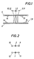
- Light sources which can be LCDs, light bulbs, laser diodes or lasers, were provided with 1, 2, optical scanning grids with 5, their imaginary second arrangement with 5 ', the two graduation tracks of scale 6 with 7 and 8 and the photo receivers assigned to the two graduation tracks 9, 10, 11, 12. 1 to 5 and 9, the collimator lenses indicated in the other figures by rectangular representation of the light sources 1, 2 have not been drawn for the sake of simplicity.
- the scanning grating 5 is designed as a step grating in which the crossbeams 13 are narrower than the depressions 14.
- the graduation tracks 7, 8 of the scale are designed as a grid with the same width of the bars and gaps 15, 16.
- the scanning grating and the graduation tracks have the same graduation period, but arrangements are also readily possible in which the graduation period of the scale tracks 7, 8 deviates from the graduation period of the scanning grid 15.
- the two graduation tracks 7, 8 of the scale 6 are mutually offset by 1/8 of the lattice constant. 1 to 4, a separate light source 1, 2 is provided for each scale track 7, 8.
- the light emitted by these light sources is diffracted as it emerges from the scanning grating 5 and is thus fanned out in the longitudinal direction of the scale 6, the reflection tracks and diffraction of the light on the gratings of the graduation tracks 7, 8 a diffraction pattern is created which falls back onto the scanning grating 5 and is again bent by the scanning grating.
- the photo receivers 9, 10 and 11, 12 are arranged so that they detect the interference of the light beams diffracted in the respective direction, the scanning grating 5 being designed so that the signals from the photo elements 9 and 10 and the signals from the photo elements 11 and 12 are out of phase by 180 °.
- the intensity of the light falling on the photo elements 9 to 12 also changes depending on the adjustment direction, so that the adjustment direction can be defined from the signals.
- the receivers 9, 10 and 11, 12 are subsequently connected in anti-parallel connection, so that the signals that can be removed from this parallel connection are largely independent of interference by changing the overall illuminance and the optical density in the beam path.
- These signals arise in their basic form as sinusoidal signals, the signal length of which corresponds to half the division constant of the grating of the scale graduation tracks 7, 8.
- the signals can be amplified, reshaped and, via trigger circuits or the like, into digital count signals for the control of display units, machine controls and the like.
- Converted although in the exemplary embodiments only linear scales 6, which in practice extend over the entire measuring length, were illustrated, but of course an analog arrangement with a measuring rod 6 lying on a circular ring is also possible for the angle measurement.
- scale 6 will be attached to the circumference of a cylindrical drum.
- reference marks can also be applied between the graduation tracks or on both sides outside of these graduation tracks 7, 8, for countermarks, lighting devices and receivers on the scanning grating are provided and which generate a detectable reference pulse for defining a scale zero or the like in a very specific relative adjustment of the scanning unit to the scale.
- the grids of the scanning grating 5 and the scale partial tracks 7, 8 have been greatly enlarged and exaggerated in the exemplary embodiments.
- grating constants of the order of ⁇ m and with step heights of the grids kept even smaller than the grating constant are used, the step heights and the gap-bar ratio of the scanning grids 5 also being dependent on the wavelength of the light used.
- a single light source 1 which emits a light beam which is fanned out across the grating 5 via an optical diffraction grating 17, so that these fanned out partial beams which are diffracted for the first time on the grating 5 fall on the two scale partial tracks , be reflected there with further diffraction and finally reach the receivers 9, 10, 11, 12 via the grating 5 '.
- FIG. 6 shows a similar arrangement, in which the light from a light source 1 is additionally collected by a condenser lens arrangement 18 and then fanned out on the grating 17, the partial beams of the selected interference image group also being guided through the condenser lens again before they are turned on the receivers 9 to 12 fall.
- the optical grating 17 of FIGS. 5 and 6 is replaced by two triangular prisms 19, 20 deflecting the light beam through the grating 5 to the scale graduation marks 7, 8.
- the two scale sub-tracks 7, 8 and the receivers 9, 10 and 11, 12 assigned to them are each assigned their own condenser lens arrangements 21, 22, which separate the light coming from the light source 1 via the grating 5 to the scale sections and direct selected interference image groups to the receivers 9, 10 or 11, 12.
Description
Die Erfindung betrifft eine photoelektrische Positionsmeßeinrichtung, mit einem reflektierenden Maßstab-Phasengitter, einem relativ zum Maßstab verstellbaren Abtast-Phasengitter, wenigstens einer relativ zu dem Abtast-Phasengitter feststehenden Lichtquelle und Photoempfängern, die Gruppen bestimmter Beugungsordnung aus dem durch die zweimalige Beugung des Lichtes an dem Abtast-Phasengitter und durch die Beugung am Maßstab-Phasengitter entstehenden Interferenzbild empfangen und entsprechend deren Intensitätsänderungen bei der Relativverstellung von Abtast- und Maßstab-Phasengittern periodische, gegeneinander phasenverschobene Meßsignale erzeugen.The invention relates to a photoelectric position measuring device, having a reflective scale phase grating, a scanning phase grating which can be adjusted relative to the scale, at least one light source which is fixed relative to the scanning phase grating, and photodetectors, the groups of specific diffraction order from which by the double diffraction of the light on the Receiving the scanning phase grating and the interference image resulting from the diffraction on the scale phase grating and generating periodic, mutually phase-shifted measurement signals in accordance with their changes in intensity during the relative adjustment of scanning and scale phase gratings.
Derartige Positionsmeßeinrichtungen arbeiten nach dem Prinzip des sogenannten Dreigitter-Schrittgebers, der einen relativ einfachen Aufbau hat. Eine entsprechende Positionsmeßeinrichtung ist aus der GB-PS 1 474 049 bekannt. Bei diesen bekannten Meßeinrichtungen werden grundsätzlich immer die 0-te, also ungebeugte Gruppe und einen gleichen positiven und negativen Phasenversatz aufweisende Gruppen des Beugungsbildes für die Auswertung mittels der Photoempfänger erfaßt, wobei aus diesen Signalen die Bewegungsrichtung des Abtastgitters gegenüber dem als reflektierendes Phasengitter ausgebildeten Maßstab und auch das Ausmaß der Verstellung des Abtastgitters gegenüber dem Maßstab bestimmt werden kann. Nach der DE-0S 23 16 248 sind bei einer entsprechenden Anordnung drei Photoempfänger vorgesehen, welche die 0-te Gruppe des Beugungsbildes und die positiven und negativen Beugungsbilder erster Ordnung erfassen. Eine Sonderausführung der letztgenannten Anordnung ist aus der EP-B-O 163 362 bekannt. Dort wird durch eine Sonderausbildung des Abtastgitters durch ein von 1 : 1 abweichendes Steg : Lückeverhältnis, beispielsweise in der Größenordnung von 1 : 3 und entsprechende Abstimmung der Stufenhöhe sowie durch entsprechende Anpassung der Anordnung der Photoempfänger eine Erhöhung der Unempfindlichkeit hinsichtlich einer Änderung des Phasenversatzes durch Abstandsänderungen der Gitter und einen Empfang der Beugungsgruppen O-ter und positiver und negativer erster Ordnung angestrebt, drei möglichst genau um 120° gegeneinander phasenverschobene Meßsignale zu erhalten. Der Phasenversatz kann im wesentlichen erreicht werden, doch hat sowohl dieses letztgenannte Positionsmeßeinrichtung als auch alle anderen bekannten Einrichtungen entscheidende Nachteile. Zunächst kann sich die Absoluthöhe bzw. die absolut betrachtete Änderung der Signale abhängig von der Beleuchtungsstärke, den Abständen zwischen den Gittern und den optischen Verlusten während des Meßvorganges ändern, so daß die Maßsignale vor der Verarbeitung normalisiert werden müssen und weiterhin lassen sich aus drei um 120° gegeneinander phasenverschobenen Signalen nicht unmittelbar für die Länge- oder Winkelmessung brauchbare Meßsignale ableiten. Es ist vielmehr notwendig, durch Umformung und Umrechnung aus diesen drei Signalen zunächst zwei um 90° phasenverschöbene analoge, sinusähnliche Signale zu bilden, aus denen dann nach bei normalen Inkrementalmeßsystemen üblichen Verfahren digitale Zählsignale gewonnen werden, die für die Steuerung von Vor-Rückwärtszähleinrichtungen und damit in weiterer folge für die Angabe des zurückgelegten Linear- oder Drehweges verwendbar sind.Such position measuring devices work on the principle of the so-called three-grating pacemaker, which has a relatively simple structure. A corresponding position measuring device is known from GB-
Zur Vermeidung von Störungen durch innere Reflexe ist es bei gattungsmäßig anderen Positionsmeßeinrichtungen bekannt, wenigstens ein transparentes Phasengitter zu verwenden und die gebeugten Teilstrahlenbündel über eine optische Umlenkeinrichtung durch das bzw. die Gitter im Abstand vom Einfallsbereich des Lichtes zurück zu Empfängern zu leiten. Hier wird vorzugsweise ein Laser als Lichtquelle verwendet. In weiterer Folge werden wieder Beugungsbilder der 0-ten und positive und negative Beugungsbilder einer n-ten Ordnung über Photodetektoren erfaßt, zur Gewinnung von drei um 120° phasenverschobenen Signalen eingesetzt und aus ihnen durch die schon erwähnte Umrechnung und Umformung Meßsignale erzeugt. Aus der EP-A-0 387 481 ist es bekannt, als Maßstab nur ein Phasengitter zu verwenden, im Durchlichtverfahren zu arbeiten und zwei kohärente Teilstrahlenbündel des Lichtes mit Einfallswinkeln gegenüber der Normalen auf das Gitter einzuleiten, so daß diese Teilstrahlenbündel am Gitter gebeugt werden, miteinander interferieren und von Photoempfängern einer Meßeinrichtung aus dem Interferenzbild wieder Meßsignale gewonnen werden können. Auch bei Zweigitteranordnungen ist es bekannt, das Licht unter einem gegebenen Einfallswinkel in das erste Gitter einzuleiten, um so die Verstellrichtung bei der Messung leichter detektieren zu können und hinreichend differenzierte Beugungsbilder zur Erfassung durch die Photodetektoren zu erhalten.To avoid interference from internal reflections, it is known in the case of other position measuring devices of the generic type to use at least one transparent phase grating and to guide the diffracted partial beam bundles back to receivers via an optical deflection device through the grating (s) at a distance from the area of incidence of the light. Here, a laser is preferably used as the light source. In a further consequence, diffraction images of the 0th and positive and negative diffraction images of an nth order are acquired again via photodetectors, used to obtain three signals which are phase-shifted by 120 °, and measurement signals are generated from them by the conversion and transformation already mentioned. From EP-A-0 387 481 it is known to use only a phase grating as a yardstick, to work in the transmitted light method and to introduce two coherent partial light beams onto the grating with angles of incidence relative to the normal, so that these partial light beams are diffracted on the grating, interfere with each other and measurement signals can be obtained again from the interference image by photo receivers of a measuring device. In two-grating arrangements, too, it is known to introduce the light into the first grating at a given angle of incidence in order to be able to more easily detect the direction of adjustment during the measurement and to obtain sufficiently differentiated diffraction images for detection by the photodetectors.
Aus der EP-A-0 223 009 ist es bekannt, am Abtastgitter in Verstellrichtung gesehen hintereinander zwei um ein Viertel der Gitterkonstante versetzte Phasengitter vorzusehen, die überdies ein von 1 : 1 abweichendes Steg/Furchenverhältnis aufweisen müssen. Hier erstreckt sich der Meßbereich über eine relativ große Länge des Maßstabes und die Anordnung wird aufwendig. Es ergibt sich allerdings der Vorteil, daß durch Zusammenführung der empfangenen Signale aus den Photoempfängern Signalnormalisierungen möglich werden. Für jede Gitterhälfte werden drei Photoempfänger wieder für die in der jeweiligen Richtung gebeugten Strahlenbündel vorgesehen.From EP-A-0 223 009 it is known to provide two phase grids, one after the other, offset by a quarter of the grating constant on the scanning grating, as seen in the adjustment direction, which must also have a ridge / groove ratio that deviates from 1: 1. Here, the measuring range extends over a relatively long length of the scale and the arrangement becomes complex. However, there is the advantage that signal normalization is possible by merging the received signals from the photo receivers. For each half of the grating, three photoreceivers are again provided for the beams that are diffracted in the respective direction.
Die Verwendung eines Maßstabes mit zwei um 1/8 der Teilung versetzten Teilungsspuren ist bei einer sich gattungsmäßig von den eingangs beschriebenen Positionsmeßeinrichtungen unterscheidenden Meßeinrichtung nach der FR-A 2 615 281 bekannt. Bei dieser Meßeinrichtung wird das Licht einer Lichtquelle in zwei Teilstrahlenbündel geteilt, die auseinandergeleitet werden und in großem Abstand voneinander auf Abtastgitter fallen, deren Aufgabe darin besteht, das von ihnen gebeugte Licht ganz exakt auf eine gemeinsame Fläche eines reflektierenden Gittermaßstabes abzuleiten. Die auf der Achse des halben Einfallswinkels der beiden von den Abtastgittern gebeugten Lichtstrahlen interferierenden Lichtbündel werden nach verschiedenen Systemen verarbeitet, wobei die Interferenzbilder über Teilprismen ausgeblendet und zu Photoempfängern geleitet werden, bei denen ein Phasenversatz der Signale auftritt. Werden nur zwei Empfänger eingesetzt, dann werden am Maßstab, wie erwähnt, zwei um 1/8 der Teilung versetzte Teilungsspuren verwendet, um in diesen beiden Empfängern phasenversetzte Signale zu erzielen. Da gesonderte Abtastgitter im Abstand voneinander Verwendung finden, können schon bei geringsten Verkippungsfehlern der Abtastgitter gegenüber dem Maßstab Signalverfälschungen und Meßfehler auftreten.The use of a scale with two graduation tracks offset by 1/8 of the graduation is known in a measuring device according to FR-A 2 615 281 which differs generically from the position measuring devices described at the outset. In this measuring device, the light from a light source is divided into two partial beams, which are guided apart and fall at a large distance from one another on scanning grids, the task of which is to lead the light diffracted by them exactly onto a common surface of a reflecting grating scale. The light bundles interfering on the axis of half the angle of incidence of the two light beams diffracted by the scanning gratings are processed according to different systems, the interference images being faded out via partial prisms and being passed to photodetectors in which a phase shift of the signals occurs. If only two receivers are used, then on the scale, as mentioned, two division tracks offset by 1/8 of the division are used in order to achieve phase-shifted signals in these two receivers. Since separate scanning grids are used at a distance from one another, signal scraps and measuring errors can occur even with the smallest tilting errors compared to the scale.
Aus den Patent Abstracts of Japan Vol. 8 Nr. 215 ist eine Positionsmeßeinrichtung bekannt, bei dem das von einer Lichtquelle kommende Licht zunächst parallelgerichtet und dann in einem halbdurchlässigen Spiegel geteilt wird, so daß ein Teil des Lichtes unmittelbar auf eine Sammellinse fällt, der andere Teil aber schräg durch einen ein optisches Gitter bildenden Maßstab auf ein relativ zur Lichtquelle feststehendes Abtastgitter geleitet, von diesem reflektiert und nach nochmaliger Beugung am Maßstab über den halbdurchlässigen Spiegel mit dem vorher abgeleiteten Anteil des Lichtes zur Interferenz gebracht wird. Durch Verwendung einer Lochblende werden nur bestimmte Beugungsordnungen ausgenutzt und auf Photoempfängern abgebildet, um so vier phasenverschobene Sinussignale zu erzeugen. Um dies zu erreichen, wird ein Abtastgitter mit acht Einzelfeldern verwendet, deren Gitter gegeneinander einen Phasenversatz von 1/8 der Gitterkonstante besitzen. Bei den an den Photoempfängern empfangenen Signalen können Schwankungen in der Signalhöhe und Phasenlage auftreten.A position measuring device is known from Patent Abstracts of Japan Vol. 8 No. 215, in which the light coming from a light source is first directed in parallel and then divided in a semi-transparent mirror, so that part of the light falls directly on a converging lens, the other Part of it, however, passed obliquely through a scale forming an optical grating onto a scanning grating fixed relative to the light source, reflected by it and, after repeated diffraction on the scale, brought into interference with the previously derived portion of the light via the semi-transparent mirror. By using a pinhole, only certain diffraction orders are used and imaged on photodetectors in order to generate four phase-shifted sinusoidal signals. To achieve this, a scanning grating with eight individual fields is used, the grids of which have a phase offset of 1/8 of the grating constant. With the signals received at the photoreceivers, fluctuations in the signal height and phase position can occur.
Aufgabe der Erfindung ist die Schaffung einer nach dem Prinzip des Dreigitter-Schrittgebers arbeitenden photoelektrischen Positionsmeßeinrichtung, bei der ein einfacher Aufbau ermöglicht wird, eine Unempfindlichkeit gegen Schwankungen der absoluten Höhe der empfangenen Signale gegeben ist und bei der die empfangenen Signale mit einfachen Mitteln korrigiert und in für die Weiterverarbeitung geeignete Meßsignale, insbesondere digitale Zählsignale, umgewandelt werden können.The object of the invention is to provide a photoelectric position measuring device which operates on the principle of the three-grating pacemaker, in which a simple construction is made possible, insensitivity to fluctuations in the absolute level of the received signals is given, and in which the received signals are corrected with simple means and in Measurement signals suitable for further processing, in particular digital count signals, can be converted.
Die gestellte Aufgabe wird durch die Merkmalskombination des Patentanspruches 1 gelöst.The object is achieved by the combination of features of
Durch die Verwendung versetzter Teilungsspuren, aber eines gemeinsamen Phasengitters für die Abtastung, wird praktisch nur ein ganz bestimmter Maßstabbereich jeweils für die Erzeugung der Meßsignale ausgenutzt, wobei Verkippungsfehler weitgehend ausscheiden und einfache Korrekturmöglichkeiten bestehen. Es ist möglich, mit nebeneinander in einer quer zur Meßrichtung verlaufenden Reihe angeordneten Photoempfängern zwei genau um 90° phasenversetzte Signale zu erzeugen, wobei durch entsprechende.By using offset graduation tracks, but a common phase grating for the scanning, practically only a very specific scale range is used in each case for the generation of the measurement signals, with tilting errors largely being eliminated and simple correction options being available. It is possible to generate two signals exactly offset by 90 ° with one another in a row running transversely to the measuring direction, with appropriate signals.
Bemessung der Gitter (Steg/Furchenverhältnis, Furchentiefe) die Möglichkeit besteht, an jeder Maßstabspur je zwei um 180° untereinander phasenverschobene Signale zu erhalten.Dimensioning of the grating (web / groove ratio, groove depth) it is possible to obtain two signals that are 180 ° out of phase with each other on each scale track.
Somit erhält man bei der erfindungsgemäßen Positionsmeßeinrichtung die in der inkrementalen Längenmeßtechnik üblichen vier Signale![]()
![]()
![]()
![]()
![]()
![]()
Durch Antiparallelschaltung der von den in einer Längsreihe angeordneten Photoempfängern erhaltenen Signale I und II bzw. III und IV wird das Meßsignal vom Gleichspannungsanteil befreit und daher weitestgehend von der Absoluthöhe des Signales unabhängig, so daß die optische Durchlässigkeit der Gitter und Änderungen der Beleuchtungsstärke die Messung kaum mehr beeinflussen. Die aus den Antiparallelschaltungen erhaltenen sinusähnlichen Signale können nach entsprechender Verstärkung in bekannter Weise als einander verstellrichtungsabhängig vor- bzw. nacheilende analoge Meßsignale für die Erzeugung von digitalen Zählsignalen verwendet werden, wobei dem Prinzip nach gleiche Auswertungsschaltungen wie bei üblichen Inkrementalmeßsystemen mit photoelektrischer Abtastung des Maßstabes durch gegeneinander phasenverschobene Gitter verwendet werden können. Selbstverständlich kann man bei der erfindungsgemäßen Positionsmeßeinrichtung zusätzlich zu den Teilungsspuren des Maßstabes in eigenen Spuren oder zwischen den Teilungsspuren Referenzmarken anbringen, die vorteilhaft ebenfalls Phasengitter bilden und von mit ihnen zusammenwirkenden Abtastgitterbereichen und Photoempfängern, die hier vorzugsweise die 0-te Ableitung des Interferenzbildes auswerten, erfaßt werden können. Bei Verwendung von zwei Lichtquellen für die beiden Teilungsspuren wird man möglichst monochromatische Lichtquellen verwenden, denen, falls erforderlich, ein Kollimator nachgeordnet wird, die aber auch von einem Laser gebildet sein können. Es genügt, das Licht jeweils nur in Form eines schmalen Streifens auszusenden.By anti-parallel connection of the signals I and II or III and IV received from the photo-receivers arranged in a longitudinal row, the measurement signal is freed from the DC voltage component and therefore largely independent of the absolute height of the signal, so that the optical transmission of the grating and changes in illuminance scarcely affect the measurement influence more. After corresponding amplification, the sine-like signals obtained from the anti-parallel circuits can be used in a known manner as analog measurement signals that advance or lag behind one another in the direction of adjustment for the generation of digital counting signals, with the principle of the same evaluation circuits as in conventional incremental measurement systems with photoelectric scanning of the scale by means of one another phase-shifted gratings can be used. Of course, in the position measuring device according to the invention, in addition to the graduation traces of the scale, reference marks can also be applied in individual traces or between the graduation traces, which advantageously also form phase gratings and are detected by cooperating scanning grating regions and photo receivers, which here preferably evaluate the 0th derivative of the interference image can be. If two light sources are used for the two graduation tracks, monochromatic light sources will be used where possible, which, if necessary, will be followed by a collimator, but which can also be formed by a laser. It is sufficient to send out the light only in the form of a narrow strip.
Eine bevorzugte andere Ausführung ist im Anspruch 2 angegeben. Dabei kann Anordnung und Teilung des Beugungsgitters so gewählt werden, daß der größte Anteil des eingeleiteten Lichtes auf die Photoempfänger fällt. Durch entsprechende Wahl des Abtastgitters, dessen Steg-/Furchenbreite und dessen Furchentiefe unter Berücksichtigung der Wellenlänge des eingesetzten Lichtes wird erreicht, daß ein hoher Anteil des Lichtes in der gewählten Gruppenordnung des Beugungsbildes gebeugt und damit für die Messung ausgenützt wird.A preferred other embodiment is specified in
Eine andere Möglichkeit der Verwendung nur einer Lichtquelle ist im Anspruch 3 angegeben.Another possibility of using only one light source is specified in claim 3.
Vor allem für herkömmliche, divergente Lichtquellen empfiehlt sich eine Ausführungsform nach Anspruch 4, wobei die Kondensorlinsenanordnung auch die entsprechenden Anteile des Interferenzbildes auf die Photoempfänger konzentriert. Nach einer Variante ist hier auch eine Ausführung nach Anspruch 5 möglich.Especially for conventional, divergent light sources, an embodiment according to claim 4 is recommended, the condenser lens arrangement also concentrating the corresponding portions of the interference image on the photoreceivers. According to a variant, an embodiment according to
Weitere Einzelheiten und Vorteile des Erfindungsgegenstandes entnimmt man der nachfolgenden Zeichnungsbeschreibung.Further details and advantages of the subject matter of the invention can be found in the following description of the drawings.
In der Zeichnung ist der Erfindungsgegenstand beispielsweise veranschaulicht. Es zeigen
- Fig. 1
- in stark schematisierter Darstellungsweise eine mögliche prinzipielle Anordnung bei einer erfindungsgemäßen Positionsmeßeinrichtung von der Seite her gesehen,
- Fig. 2
- eine Draufsicht zu Fig. 1 zur Veranschaulichung der Relativanordnung von Beleuchtungseinrichtungen und photoelektrischen Empfängern,
- Fig. 3
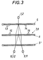
- eine hinsichtlich der Lichtquelle abgewandelte, im übrigen aber der Fig. 1 entsprechende Schemadarstellung, bei der zur Verdeutlichung der Funktionsweise das Abtastgitter für die Strahlendurchgänge zweimal, nämlich vor und hinter dem transparent gedachten Maßstab dargestellt wurde,
- Fig. 4
- ein der Fig. 3 entsprechendes Schaubild,
- Fig. 5
- in einer der Fig. 4 entsprechenden Darstellungsweise eine Ausführungsvariante mit nur einer Lichtquelle,
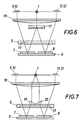
- Fig. 6
- in einem sinngemäß eine Queransicht zu Fig. 1 darstellenden Schema eine weitere Ausführungsvariante,
- Fig. 7
- eine andere Ausführung wieder in einer schematischen Darstellung gemäß Fig. 6 und
- Fig. 8
- eine andere Ausführung in einer schematischen Darstellung gemäß Fig. 6
- Fig. 1
- a possible schematic arrangement of a position measuring device according to the invention seen from the side in a highly schematic representation,
- Fig. 2
- 1 shows a top view of FIG. 1 to illustrate the relative arrangement of lighting devices and photoelectric receivers,
- Fig. 3
- a modified with respect to the light source, but otherwise corresponding to FIG. 1, in which the scanning grating for the beam passages was shown twice, namely in front of and behind the transparent scale, to clarify the mode of operation,
- Fig. 4
- 3 shows a diagram corresponding to FIG.
- Fig. 5
- 4 shows an embodiment variant with only one light source,
- Fig. 6
- 1 shows a further embodiment variant in a diagram corresponding to a transverse view to FIG. 1,
- Fig. 7
- another embodiment again in a schematic representation according to FIG. 6 and
- Fig. 8
- another embodiment in a schematic representation according to FIG. 6
In den Fig. 1 bis 8 der Zeichnung werden gleiche Teile mit gleichen Bezugszeichen bezeichnet. Lichtquellen, die LCD's, Glühbirnen, Laserdioden bzw. Laser sein können, wurden mit 1, 2, optische Abtastgitter mit 5, ihre gedachte Zweitanordnung mit 5', die beiden Teilungsspuren des Maßstabes 6 mit 7 und 8 und die den beiden Teilungsspuren zugeordneten Photoempfänger mit 9, 10, 11, 12 bezeichnet. In den Fig. 1 bis 5 und 9 wurden die in den anderen Figuren durch Rechteckdarstellung der Lichtquellen 1, 2 angedeuteten Kollimatorlinsen der Einfachheit halber nicht gezeichnet.1 to 8 of the drawing, the same parts are designated by the same reference numerals. Light sources, which can be LCDs, light bulbs, laser diodes or lasers, were provided with 1, 2, optical scanning grids with 5, their imaginary second arrangement with 5 ', the two graduation tracks of
Das Abtastgitter 5 ist als Stufengitter ausgebildet, bei dem die Querbalken 13 schmäler als die Vertiefungen 14 ausgebildet sind. Dagegen sind die Teilungsspuren 7, 8 des Maßstabes als Gitter mit gleicher Breite der Balken und Lücken 15, 16 ausgeführt. Bei den Ausführungsbeispielen besitzen zwar das Abtastgitter und die Teilungsspuren die gleiche Teilungsperiode, doch sind ohne weiteres auch Anordnungen möglich, bei denen die Teilungsperiode der Maßstabspuren 7, 8 von der Teilungsperiode des Abtastgitters 15 abweicht. Die beiden Teilungsspuren 7, 8 des Maßstabes 6 sind gegeneinander um 1/8 der Gitterkonstante versetzt. Nach den Fig. 1 bis 4 ist für jede Maßstabspur 7, 8 eine eigene Lichtquelle 1, 2 vorgesehen. Das von diesen Lichtquellen ausgesandte Licht wird beim Austritt aus dem Abtastgitter 5 gebeugt und dadurch in Längsrichtung des Maßstabes 6 aufgefächert, wobei durch Reflexion und Beugung des Lichtes auf den Gittern der Teilungsspuren 7, 8 ein Beugungsbild entsteht, das wieder auf das Abtastgitter 5 fällt und vom Abtastgitter noch einmal gebeugt wird. Die Photoempfänger 9, 10 bzw. 11, 12 sind so angeordnet, daß sie die Interferenz der in die jeweilige Richtung gebeugten Lichtbündel erfassen, wobei das Abtastgitter 5 so gestaltet ist, daß die Signale vom Photoelement 9 und 10 sowie die Signale vom Photoelement 11 und 12 um 180° phasenversetzt sind. Bei einer Relativverstellung des Abtastgitters 5 gegenüber dem Maßstab 6 ändert sich die Intensität des Lichtes, das auf die Photoelemente 9 bis 12 fällt, auch abhängig von der Verstellrichtung, so daß die Verstellrichtung aus den Signalen definiert werden kann. Die jeweils in Querreihen nebeneinander angeordneten Empfänger 9, 11 und 10, 12 empfangen wegen des Versatzes der Teilungsspuren 7, 8 gegeneinander um 90° phasenverschobene Signale. Die Empfänger 9, 10 bzw. 11, 12 werden in weiterer Folge in Antiparallelschaltung verbunden, so daß die von dieser Parallelschaltung abnehmbaren Signale weitgehend von Störungseinflüssen durch Änderung der Gesamtbeleuchtungsstärke und der optischen Dichte im Strahlengang unabhängig werden. Diese Signale entstehen in ihrer Grundform als sinusähnliche Signale, deren Signalzuglänge der halben Teilungskonstante der Gitter der Maßstabteilungsspuren 7, 8 entspricht. Die Signale können in bekannter Weise verstärkt, umgeformt und über Triggerschaltungen od. dgl. in digitale Zählsignale für die Steuerung von Anzeigeeinheiten, Maschinensteuerungen u. dgl. umgewandelt werden, wobei bei den Ausführungsbeispielen zwar nur lineare, in der Praxis über die gesamte Meßlänge reichende Maßstäbe 6 veranschaulicht wurden, selbstverständlich aber auch eine analoge Anordnung mit einem auf einem Kreisring liegenden Meßstab 6 für die Winkelmessung möglich ist. Vorzugsweise wird man hier den Maßstab 6 am Umfang einer zylindrischen Trommel anbringen. Am Maßstab können noch zwischen den Teilungsspuren oder beidseits außerhalb dieser Teilungsspuren 7, 8 Referenzmarken angebracht sein, für die am Abtastgitter Gegenmarken, Beleuchtungseinrichtungen und Empfänger vorgesehen sind und die in einer ganz bestimmten Relativverstellung der Abtasteinheit zum Maßstab einen detektierbaren Referenzimpuls zur Definition eines Maßstabnullpunktes od. dgl. erzeugen.The
Selbstverständlich wurden die Gitter des Abtastgitters 5 und der Maßstabteilspuren 7, 8 bei den Ausführungsbeispielen stark vergrößert und überhöht gezeichnet. In der Praxis wird mit Gitterkonstanten in der Größenordnung von µm und mit noch kleiner als die Gitterkonstante gehaltenen Stufenhöhen der Gitter gearbeitet, wobei die Stufenhöhen und das Lücke-Balkenverhältnis der Abtastgitter 5 auch von der Wellenlänge des eingesetzten Lichtes abhängt.Of course, the grids of the
Bei der Ausführung nach Fig. 5 ist nur eine einzige Lichtquelle 1 vorgesehen, die einen Lichtstrahl abgibt, der über ein optisches Beugungsgitter 17 quer über das Gitter 5 aufgefächert wird, so daß diese aufgefächerten, am Gitter 5 erstmalig gebeugten Teilstrahlen auf die beiden Maßstabteilspuren fallen, dort unter weiterer Beugung reflektiert werden und schließlich über das Gitter 5′ zurück auf die Empfänger 9, 10, 11, 12 gelangen.5, only a single
Nach Fig. 6 ist eine ähnliche Anordnung vorhanden, bei der das Licht einer Lichtquelle 1 aber zusätzlich durch eine Kondensorlinsenanordnung 18 gesammelt und dann am Gitter 17 aufgefächert wird, wobei auch die Teilstrahlen der ausgewählten Interferenzbildgruppe noch einmal durch die Kondensorlinse geführt werden, bevor sie auf die Empfänger 9 bis 12 fallen.6 shows a similar arrangement, in which the light from a
Bei der Ausführung nach Fig. 7 ist das optische Gitter 17 der Fig. 5 und 6 durch zwei das Lichtbündel durch das Gitter 5 zu den Maßstabteilspuren 7, 8 umlenkende Dreieckprismen 19, 20 ersetzt.7, the
Gemäß Fig. 8 sind den beiden Maßstabteilspuren 7, 8 und den ihnen zugeordneten Empfängern 9, 10 bzw. 11, 12 jeweils eigene Kondensorlinsenanordnungen 21, 22 zugeordnet, die das von der Lichtquelle 1 kommende Licht gesondert über das Gitter 5 zu den Maßstabteilstücken und die ausgewählten Interferenzbildgruppen zu den Empfängern 9, 10 bzw. 11, 12 lenken.According to FIG. 8, the two
Claims (5)
- A photoelectric position-measuring device comprising- a reflecting scale phase grating,- a scanning phase grating (5) adjustable relatively to the scale (6),- at least one light source (1, 2) which is fixed relatively to the scanning phase grating (5) and- photo-receivers (9 - 10) which receive groups of a defined diffraction order from the interference pattern resulting from double diffraction of light at the scanning phase grating (5) and diffraction at the scale phase grating and generate mutually phase-shifted measuring signals corresponding to the changes in intensity during relative movement of the scanning and the scale phase grating, and- the scale (6) has two adjacent graduation tracks (7, 8) offset by 1/8 of the grating constant,- a single common scanning phase grating (5) is provided for both tracks (7, 8),- two photo-receivers (9, 10; 11, 12) for each track (7, 8) receive the interference of the beam diffracted in this direction at a common place on the scale during scanning of the two tracks (7, 8) and- generate measuring signals which are phase-shifted by 180° and in pairs have a phase shift of 90° relative to the measuring signals obtained from the other track, owing to the offset between the tracks (7, 8) on the scale (7, 9).
- A position-measuring device according to claim 1, characterised in that an optical guide device comprises a diffraction grating (17) which spreads out the beam from a common light source (1) transversely to the longitudinal direction of the scale, between the tracks (7, 8), the associated scanning-grating regions and the photo-receivers (9 - 12).
- A position-measuring device according to claim 1, characterised in that prisms (19, 20) for dividing the light from the source among the tracks are provided on the scanning grating (5) on the side facing the light source (1).
- A position-measuring device according to any of claims 1 to 3, characterised in that a condenser lens arrangement (18, 21, 22) is provided and extends over the path of rays from the light source (1) to the phase gratings (5, 7, 8) and also over the beams for the selected order of the interference pattern.
- A position-measuring device according to any of claims 1 to 3, characterised in that separate condenser lenses (21, 22) disposed in front of the scanning grating (5) are provided for both tracks (7, 8) of the scale (6).
Applications Claiming Priority (2)
| Application Number | Priority Date | Filing Date | Title |
|---|---|---|---|
| AT813/91 | 1991-04-18 | ||
| AT0081391A AT395914B (en) | 1991-04-18 | 1991-04-18 | PHOTOELECTRIC POSITION MEASURING DEVICE |
Publications (3)
| Publication Number | Publication Date |
|---|---|
| EP0509979A2 EP0509979A2 (en) | 1992-10-21 |
| EP0509979A3 EP0509979A3 (en) | 1993-01-20 |
| EP0509979B1 true EP0509979B1 (en) | 1996-06-05 |
Family
ID=3500320
Family Applications (1)
| Application Number | Title | Priority Date | Filing Date |
|---|---|---|---|
| EP92890080A Expired - Lifetime EP0509979B1 (en) | 1991-04-18 | 1992-04-03 | Photo-electronic position-measuring device |
Country Status (4)
| Country | Link |
|---|---|
| US (1) | US5214280A (en) |
| EP (1) | EP0509979B1 (en) |
| AT (1) | AT395914B (en) |
| DE (1) | DE59206455D1 (en) |
Families Citing this family (32)
| Publication number | Priority date | Publication date | Assignee | Title |
|---|---|---|---|---|
| DE59102126D1 (en) * | 1991-05-18 | 1994-08-11 | Heidenhain Gmbh Dr Johannes | Interferential position measuring device. |
| US5519492A (en) * | 1992-06-27 | 1996-05-21 | Dr. Johannes Heidenhain Gmbh | Optical arrangement for detecting the intensity modulation of partial ray beams |
| DE59203396D1 (en) * | 1992-07-18 | 1995-09-28 | Heidenhain Gmbh Dr Johannes | Optical device. |
| US5534692A (en) * | 1992-09-14 | 1996-07-09 | Sony Corporation | Method for detecting origin point of position sensor |
| US5424833A (en) * | 1992-09-21 | 1995-06-13 | Dr. Johannes Heidenhain Gmbh | Interferential linear and angular displacement apparatus having scanning and scale grating respectively greater than and less than the source wavelength |
| JP3210111B2 (en) * | 1992-12-24 | 2001-09-17 | キヤノン株式会社 | Displacement detector |
| AT404637B (en) * | 1993-01-21 | 1999-01-25 | Rsf Elektronik Gmbh | PHOTOELECTRIC POSITION MEASURING DEVICE |
| JP3173208B2 (en) * | 1993-01-29 | 2001-06-04 | キヤノン株式会社 | Displacement measuring device |
| JPH074993A (en) * | 1993-03-23 | 1995-01-10 | Ricoh Co Ltd | Encoder apparatus |
| US5652426A (en) * | 1993-04-19 | 1997-07-29 | Ricoh Company, Ltd. | Optical encoder having high resolution |
| EP0625690B1 (en) * | 1993-05-21 | 1996-04-03 | Dr. Johannes Heidenhain GmbH | Optoelectric position measuring device |
| JP3082516B2 (en) * | 1993-05-31 | 2000-08-28 | キヤノン株式会社 | Optical displacement sensor and drive system using the optical displacement sensor |
| DE4318129A1 (en) * | 1993-06-01 | 1994-12-08 | Bosch Gmbh Robert | Device for measuring movement between two parts |
| JPH0719965A (en) * | 1993-06-30 | 1995-01-20 | Ando Electric Co Ltd | Light wavemeter |
| ATE192566T1 (en) * | 1994-02-23 | 2000-05-15 | Heidenhain Gmbh Dr Johannes | POSITION MEASURING DEVICE |
| GB9425907D0 (en) * | 1994-12-22 | 1995-02-22 | Renishaw Plc | Opto-electronic scale reading apparatus |
| DE19511068A1 (en) * | 1995-03-25 | 1996-09-26 | Heidenhain Gmbh Dr Johannes | Photoelectric position measuring device |
| ES2114796B1 (en) * | 1995-11-06 | 1999-02-16 | Fagor S Coop Ltda | OPTICAL DEVICE FOR INCREMENTAL LENGTH MEASUREMENT USING DIFFUSE LIGHT. |
| US6188058B1 (en) * | 1998-09-17 | 2001-02-13 | Agilent Technologies Inc. | System for taking displacement measurements having photosensors with imaged pattern arrangement |
| US7064842B1 (en) * | 1999-01-13 | 2006-06-20 | Olympus Optical Co., Ltd. | Optical displacement sensor and optical encoder |
| WO2004005855A2 (en) * | 2002-07-08 | 2004-01-15 | Microe Systems Corporation | Multi-track optical encoder employing beam divider |
| JP2005147828A (en) * | 2003-11-14 | 2005-06-09 | Mitsutoyo Corp | Displacement detector |
| JPWO2006006342A1 (en) * | 2004-07-12 | 2008-04-24 | 三菱電機株式会社 | Optical encoder |
| US20080203283A1 (en) * | 2007-02-23 | 2008-08-28 | Yee Loong Chin | Optical encoder with detector lens |
| CN101680780A (en) * | 2007-06-19 | 2010-03-24 | 3M创新有限公司 | Total internal reflection displacement scale |
| CN102313517B (en) * | 2011-08-23 | 2013-01-09 | 广州市诺信数字测控设备有限公司 | Optical grating ruler with double light sources |
| JP6359340B2 (en) | 2014-05-27 | 2018-07-18 | 株式会社ミツトヨ | Scale and optical encoder |
| JP6386337B2 (en) | 2014-10-23 | 2018-09-05 | 株式会社ミツトヨ | Optical encoder |
| JP6664155B2 (en) | 2015-06-11 | 2020-03-13 | 株式会社ミツトヨ | Optical encoder |
| JP6593868B2 (en) * | 2015-07-28 | 2019-10-23 | 株式会社ミツトヨ | Displacement detector |
| US9871595B2 (en) * | 2016-04-27 | 2018-01-16 | Industrial Technology Research Institute | Decoding device and method for absolute positioning code |
| CN115603630B (en) * | 2022-12-14 | 2023-03-10 | 四川大学 | Method for quickly determining reference zero point of servo motor in high-precision situation |
Family Cites Families (13)
| Publication number | Priority date | Publication date | Assignee | Title |
|---|---|---|---|---|
| DE2316248A1 (en) * | 1973-03-31 | 1974-10-10 | Leitz Ernst Gmbh | PHOTOELECTRIC STEPPER |
| GB1474049A (en) * | 1974-01-12 | 1977-05-18 | Leitz Ernst Gmbh | Arrangement for the modulation of light |
| JPS57169613A (en) * | 1981-04-13 | 1982-10-19 | Tokyo Optical Co Ltd | Photoelectric encoder |
| JPS5999219A (en) * | 1982-11-29 | 1984-06-07 | Nippon Kogaku Kk <Nikon> | Encoder using diffraction grating |
| DE3417176C2 (en) * | 1984-05-09 | 1986-07-31 | Dr. Johannes Heidenhain Gmbh, 8225 Traunreut | Photoelectric measuring device |
| GB8413955D0 (en) * | 1984-05-31 | 1984-07-04 | Pa Consulting Services | Displacement measuring apparatus |
| DE3541199C1 (en) * | 1985-11-21 | 1987-06-25 | Heidenhain Gmbh Dr Johannes | Photoelectric position measuring device |
| DE3636744C1 (en) * | 1986-10-29 | 1988-03-24 | Heidenhain Gmbh Dr Johannes | Photoelectric length or angle measuring device |
| FR2615281B1 (en) * | 1987-05-11 | 1996-08-23 | Canon Kk | DEVICE FOR MEASURING A RELATIVE MOTION DISTANCE OF TWO MOBILE OBJECTS IN RELATION TO ONE ANOTHER |
| DE3905730C2 (en) * | 1989-02-24 | 1995-06-14 | Heidenhain Gmbh Dr Johannes | Position measuring device |
| DE3908254A1 (en) * | 1989-03-14 | 1990-09-20 | Heidenhain Gmbh Dr Johannes | POSITION MEASURING DEVICE |
| JP2539269B2 (en) * | 1989-07-17 | 1996-10-02 | オークマ株式会社 | Optical encoder |
| EP0425726B1 (en) * | 1989-11-02 | 1993-05-12 | Dr. Johannes Heidenhain GmbH | Position measuring device |
-
1991
- 1991-04-18 AT AT0081391A patent/AT395914B/en not_active IP Right Cessation
-
1992
- 1992-04-03 DE DE59206455T patent/DE59206455D1/en not_active Expired - Fee Related
- 1992-04-03 EP EP92890080A patent/EP0509979B1/en not_active Expired - Lifetime
- 1992-04-10 US US07/866,907 patent/US5214280A/en not_active Expired - Lifetime
Also Published As
| Publication number | Publication date |
|---|---|
| EP0509979A2 (en) | 1992-10-21 |
| EP0509979A3 (en) | 1993-01-20 |
| US5214280A (en) | 1993-05-25 |
| ATA81391A (en) | 1992-08-15 |
| AT395914B (en) | 1993-04-26 |
| DE59206455D1 (en) | 1996-07-11 |
Similar Documents
| Publication | Publication Date | Title |
|---|---|---|
| EP0509979B1 (en) | Photo-electronic position-measuring device | |
| EP1923673B1 (en) | Position measuring device | |
| EP0513427B1 (en) | Interferometric position measuring device | |
| DE3727188C2 (en) | Optical displacement detection device | |
| DE2637361A1 (en) | DEVICE FOR MEASURING THE MOVEMENT OF A FIRST PART RELATIVE TO A SECOND PART | |
| EP1081457B1 (en) | Optical position measuring device | |
| EP1497609B1 (en) | Optical position measuring device | |
| DE3904898A1 (en) | OPTICAL ENCODER | |
| EP1003012B3 (en) | Optical position measuring arrangement | |
| DE3816247A1 (en) | DISTANCE MEASUREMENT SYSTEM | |
| EP1236023B1 (en) | Angle measuring system | |
| DE3905730C2 (en) | Position measuring device | |
| DE10132521A1 (en) | Position measuring device | |
| DE19754595A1 (en) | Photoelectric position measuring unit, to measure relative position, length or angle | |
| DE19726935B4 (en) | Optical position measuring device | |
| AT404637B (en) | PHOTOELECTRIC POSITION MEASURING DEVICE | |
| EP1028309B1 (en) | Optical encoder | |
| EP0747674B1 (en) | Photo-electric position measuring device | |
| DE10325082A1 (en) | Photoelectric rotary encoder | |
| EP0754933B1 (en) | Position measuring device | |
| DE4212281C2 (en) | ||
| DE10346380B4 (en) | Position measuring device | |
| EP3936830B1 (en) | Optical positioning device | |
| EP0626564B1 (en) | Photoelectric length and angle measuring device | |
| EP4174447B1 (en) | Optical position measuring device and method for operating an optical position measuring device |
Legal Events
| Date | Code | Title | Description |
|---|---|---|---|
| PUAI | Public reference made under article 153(3) epc to a published international application that has entered the european phase |
Free format text: ORIGINAL CODE: 0009012 |
|
| AK | Designated contracting states |
Kind code of ref document: A2 Designated state(s): BE CH DE FR GB IT LI LU NL SE |
|
| PUAL | Search report despatched |
Free format text: ORIGINAL CODE: 0009013 |
|
| AK | Designated contracting states |
Kind code of ref document: A3 Designated state(s): BE CH DE FR GB IT LI LU NL SE |
|
| 17P | Request for examination filed |
Effective date: 19930331 |
|
| 17Q | First examination report despatched |
Effective date: 19940520 |
|
| GRAH | Despatch of communication of intention to grant a patent |
Free format text: ORIGINAL CODE: EPIDOS IGRA |
|
| GRAA | (expected) grant |
Free format text: ORIGINAL CODE: 0009210 |
|
| AK | Designated contracting states |
Kind code of ref document: B1 Designated state(s): BE CH DE FR GB IT LI LU NL SE |
|
| PG25 | Lapsed in a contracting state [announced via postgrant information from national office to epo] |
Ref country code: NL Free format text: LAPSE BECAUSE OF FAILURE TO SUBMIT A TRANSLATION OF THE DESCRIPTION OR TO PAY THE FEE WITHIN THE PRESCRIBED TIME-LIMIT Effective date: 19960605 |
|
| REF | Corresponds to: |
Ref document number: 59206455 Country of ref document: DE Date of ref document: 19960711 |
|
| ITF | It: translation for a ep patent filed |
Owner name: STUDIO CONS. BREVETTUALE S.R.L. |
|
| GBT | Gb: translation of ep patent filed (gb section 77(6)(a)/1977) |
Effective date: 19960802 |
|
| PG25 | Lapsed in a contracting state [announced via postgrant information from national office to epo] |
Ref country code: SE Effective date: 19960905 |
|
| ET | Fr: translation filed | ||
| NLV1 | Nl: lapsed or annulled due to failure to fulfill the requirements of art. 29p and 29m of the patents act | ||
| PLBE | No opposition filed within time limit |
Free format text: ORIGINAL CODE: 0009261 |
|
| STAA | Information on the status of an ep patent application or granted ep patent |
Free format text: STATUS: NO OPPOSITION FILED WITHIN TIME LIMIT |
|
| PG25 | Lapsed in a contracting state [announced via postgrant information from national office to epo] |
Ref country code: LU Free format text: LAPSE BECAUSE OF NON-PAYMENT OF DUE FEES Effective date: 19970430 Ref country code: LI Free format text: LAPSE BECAUSE OF NON-PAYMENT OF DUE FEES Effective date: 19970430 Ref country code: CH Free format text: LAPSE BECAUSE OF NON-PAYMENT OF DUE FEES Effective date: 19970430 Ref country code: BE Effective date: 19970430 |
|
| 26N | No opposition filed | ||
| REG | Reference to a national code |
Ref country code: CH Ref legal event code: PL |
|
| REG | Reference to a national code |
Ref country code: GB Ref legal event code: IF02 |
|
| PGFP | Annual fee paid to national office [announced via postgrant information from national office to epo] |
Ref country code: GB Payment date: 20070426 Year of fee payment: 16 |
|
| PGFP | Annual fee paid to national office [announced via postgrant information from national office to epo] |
Ref country code: IT Payment date: 20070626 Year of fee payment: 16 |
|
| PGFP | Annual fee paid to national office [announced via postgrant information from national office to epo] |
Ref country code: FR Payment date: 20070416 Year of fee payment: 16 |
|
| PGFP | Annual fee paid to national office [announced via postgrant information from national office to epo] |
Ref country code: DE Payment date: 20080418 Year of fee payment: 17 |
|
| GBPC | Gb: european patent ceased through non-payment of renewal fee |
Effective date: 20080403 |
|
| REG | Reference to a national code |
Ref country code: FR Ref legal event code: ST Effective date: 20081231 |
|
| PG25 | Lapsed in a contracting state [announced via postgrant information from national office to epo] |
Ref country code: FR Free format text: LAPSE BECAUSE OF NON-PAYMENT OF DUE FEES Effective date: 20080430 |
|
| PG25 | Lapsed in a contracting state [announced via postgrant information from national office to epo] |
Ref country code: GB Free format text: LAPSE BECAUSE OF NON-PAYMENT OF DUE FEES Effective date: 20080403 |
|
| PG25 | Lapsed in a contracting state [announced via postgrant information from national office to epo] |
Ref country code: IT Free format text: LAPSE BECAUSE OF NON-PAYMENT OF DUE FEES Effective date: 20080403 |
|
| PG25 | Lapsed in a contracting state [announced via postgrant information from national office to epo] |
Ref country code: DE Free format text: LAPSE BECAUSE OF NON-PAYMENT OF DUE FEES Effective date: 20091103 |