EP0509903B1 - Process and apparatus for measuring axial eye length - Google Patents
Process and apparatus for measuring axial eye length Download PDFInfo
- Publication number
- EP0509903B1 EP0509903B1 EP92401042A EP92401042A EP0509903B1 EP 0509903 B1 EP0509903 B1 EP 0509903B1 EP 92401042 A EP92401042 A EP 92401042A EP 92401042 A EP92401042 A EP 92401042A EP 0509903 B1 EP0509903 B1 EP 0509903B1
- Authority
- EP
- European Patent Office
- Prior art keywords
- light
- interference
- cornea
- eye
- retina
- Prior art date
- Legal status (The legal status is an assumption and is not a legal conclusion. Google has not performed a legal analysis and makes no representation as to the accuracy of the status listed.)
- Expired - Lifetime
Links
Images


Classifications
-
- A—HUMAN NECESSITIES
- A61—MEDICAL OR VETERINARY SCIENCE; HYGIENE
- A61B—DIAGNOSIS; SURGERY; IDENTIFICATION
- A61B3/00—Apparatus for testing the eyes; Instruments for examining the eyes
- A61B3/10—Objective types, i.e. instruments for examining the eyes independent of the patients' perceptions or reactions
- A61B3/1005—Objective types, i.e. instruments for examining the eyes independent of the patients' perceptions or reactions for measuring distances inside the eye, e.g. thickness of the cornea
Definitions
- This invention relates to a process and apparatus for measuring the axial eye length wherein monochromatic coherent light of which wavelengths are variable is projected onto an eyeball to be tested, reflected light from the retina of the eye is interfered with reference light corresponding to the retina to obtain interference signals while reflected light from the cornea of the eye is interfered with reference light corresponding to the cornea to obtain interference signals, these interference signals are mixed to produce beat signals while varying the wavelength, and the axial eye length is obtained based on the beat signals.
- this invention relates to a process and apparatus for measuring the axial eye length wherein laser beam of light emitted from a laser source of which oscillation wavelengths are variable is split into measuring laser beam of light and reference laser beam of light, the measuring laser beam of light is projected onto the eye, light reflected from the cornea of the eye is interfered with light reflected from the retina of the eye, and the axial length of an eye is obtained based on the interference light.
- EP-A-0 348 057 and (2) JP-A-2 295 536 give examples of ophthalmic diagnostic method and apparatus for measuring an eye length between the cornea and the fundus of the eye.
- the conventional apparatus has drawbacks such as that too strong coherent light must not be projected onto the eye because it causes inflammations of the retina or damage thereto, intensive interference light cannot be obtained because the reflectances of the retina and cornea are lower, or adequate photoelectric transfer signals in S/N (signal-to-noise) ratio cannot be obtained because the photoelectric transfer signals based on the interference light are too weak, Further, the photoelectric transfer signals are inconstant owing to the optically coarse surface of the retina, a clear distinction between the signals and noises is seldom made owing to weakness of the signals, hence, it is difficult to measure the axial eye length accurately.
- An object of the present invention is to provide a process and apparatus for measuring an axial eye length in which measured values can be easily and correctly obtained without enhancing the intensity of coherent light needlessly, in other words, irrespective of weakness of the lights reflected form the retina and the cornea.
- the present invention provides an apparatus as claimed in independent claims 1 and 3 and a process as claimed in independant claims 4 and 5.
- Fig. 1 is a view showing an optical system of a first embodiment of the present invention.
- Fig. 2 is a block chart showing circuits for processing signals to obtain an axial eye length using the optical system of Fig. 1.
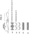
- Fig. 3 explains waveforms of the signal of the signal processing circuit of Fig. 2.
- Fig. 4 is a block chart showing a signal processing circuit of another embodiment.
- Fig. 5 explains waveforms of the signal of the signal processing circuit of Fig. 4.
- Fig. 6 is a view showing a low-pass filter.
- Fig. 7 is a timing chart for explaining the function of a frequency divider.
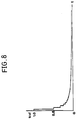
- Fig. 8 is a graph showing the variation of a cutoff frequency.
- Fig. 9 is a view showing an optical system of a variant of the first embodiment.
- Fig. 10 is a view showing an optical system of a second embodiment of the present invention.
- Fig. 11 is a flow chart showing circuits for processing signals to obtain an axial eye length based on a beat signal.
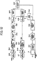
- Fig. 12 is a block chart showing circuits for processing signals to obtain the axial eye length using a reference interference optical system.
- Fig. 13 explains waveforms of the signal of the signal processing circuit of Fig. 12.
- Fig. 14 is a block chart showing circuits for processing signals of another embodiment of a measuring apparatus in Fig. 12.
- Fig. 15 explains waveforms outputted from circuits of a signal processing circuit of Fig. 14.
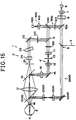
- Fig. 16 is a view showing an optical system of a third embodiment of the present invention.
- Fig. 17 is a view shoving an optical system of a fourth embodiment of the present invention.
- the measuring optical system 1 includes a beam splitter 3 by which the optical system 1 is split into a retina measuring optical system 4 and a cornea measuring optical system 5.
- the measuring optical system 1 also includes a semiconductor laser 6 to emit monochromatical coherent light.
- the coherent light is converted into parallel beam by means of a collimator lens 7.
- the parallel beams of light are guided to a beam splitter 9 via an optical light isolator 8 which serves to prevent reflected light as mentioned below from returning to the semiconductor laser 6.
- the semiconductor laser 6 is, therefore, preventable against modulation distortion caused by the return of the reflected light.
- the beam splitter 9 splits the parallel beams of light into two parts one of which is guided to the reference interference optical system 2 and the other one of which is guided to the beam splitter 3 through the beam splitter 9 as measuring light.
- the beam splitter 3 splits the measuring light into retina measuring light, which is guided to the retina measuring optical system 4, and cornea measuring light which is guided to the cornea measuring optical system 5.
- the retina measuring optical system 4 includes a beam splitter 10, lens 11, lens 12, diaphragm 13, mirror 14, movable lens 15, beam splitter 16, objective lens 17 toward an eyeball or eye to be tested E, reference surface 18 corresponding to the retina, converging lens 19, and light receiver 20.
- the diaphragm 13 which serves as a low-pass filter in co-operation with the Fourier transform carried out by the lenses 11 and 12 is disposed between the lenses 11 and 12. The arrangement of the lenses 11 and 12 and diaphragm 13 is well known.
- the retina measuring light is split in two directions.
- One of the split lights is guided to the reference surface 18 corresponding to the retina, it is reflected from the surface 18, it returns along the same optical path, it passes through the beam splitter 10, and it is converged upon the receiver 20 by the converging lens 19.
- the other one passes through the lens 11, diaphragm 13 and lens 12, it is reflected from the mirror 14, it is guided to the beam splitter 16 via the movable lens 15, it is reflected by the beam splitter 16, and it is projected onto the eyeball E through the objective lens 17.
- the movable lens 15 serves to converge the retina measuring light upon the retina R by correcting the refracting power of the eye to be tested.
- the cornea measuring optical system 5, of which an optical axis is coaxial with that of the objective lens 17 by means of the beam splitter 16, includes a beam splitter 21, mirror 22, compensating plate 23 for an optical path length, lens 24, diaphragm 25, reference surface 26 corresponding to the cornea, converging lens 27, and light receiver 28.
- the diaphragm 25 serves as a low-pass filter in co-operation with the Fourier transform carried out by the objective lens 17 and lens 24.
- the beam splitter 21 the cornea measuring light is split in two directions. One of the split lights is guided to the reference surface 26 corresponding to the cornea, it is reflected from the surface 26 and returns along the same optical path, it passes through the beam splitter 21, and it is converged upon the receiver 28 by the converging lens 27.
- the other one passes through the mirror 22, compensating plate 23 for an optical path length, lens 24, diaphragm 25, beam splitter 16, objective lens 17, and it is converged upon the apex M of the cornea C.
- Light reflected from the apex M of the cornea C returns along the same optical path, it passes through the objective lens 17, beam splitter 16, diaphragm 25, compensating plate 23, and mirror 22, and it is guided to the beam splitter 21. Scattered components included in the reflected light from the cornea C are eliminated at the lens 17, diaphragm 25, and lens 24.
- thermometer controlling means such as the Peltier effect type of element in order to controlling the wavelength of coherent light emitted from the semiconductor laser 6.
- the numeral 33 designates a synchronization controlling circuit which outputs synchronizing signals to a clock circuit 34 and wavelength controlling circuit 35.
- the wavelength controlling circuit 35 outputs to a driving circuit 36 and wavelength controlling means 37.
- the intensity I1 of the interference light in the light receiver 20 is theoretically subject to the following equation.
- I1 2Ar ⁇ Aref1 ⁇ cos ⁇ 2 ⁇ 2(Lr-L1)/ ⁇
- Ar is an amplitude of the light reflected from the retina R
- Aref1 is an amplitude of the light reflected from the reference surface 18 corresponding to the retina
- ⁇ is a wavelength of the coherent light
- 2 ⁇ ⁇ 2(Lr-L1)/ ⁇ denotes the difference in phase of the interference light.
- the intensity I2 of the interference light in the light receiver 28 is theoretically subject to the following equation.
- I2 2Ac ⁇ Aref2 ⁇ cos ⁇ 2 ⁇ 2(Lc-L2)/ ⁇
- Ac an amplitude of the light reflected from the cornea C
- Aref2 an amplitude of the light reflected from the reference surface 26 corresponding to the cornea
- ⁇ is a wavelength of the coherent light
- 2 ⁇ ⁇ 2(Lc-L2)/ ⁇ denotes the difference in phase of the interference light.
- a phase difference of the interference light at the light receiver 20 is also varied to 2 ⁇ ⁇ 2(Lr-L1)/( ⁇ + ⁇ ) and a phase difference of the interference light at the light receiver 28 to 2 ⁇ ⁇ 2(Lc-L2)/( ⁇ + ⁇ ) .
- each phase difference When the term of each phase difference is developed in progression (series) with the condition of ⁇ » ⁇ ⁇ , the amount of variation of each phase difference is denoted as follows: 2 ⁇ ⁇ 2(Lr-L1) ⁇ / ⁇ 2 , 2 ⁇ ⁇ 2(Lc-L2) ⁇ / ⁇ 2 Since the intensities I1 and I2 of the interference light are periodically varied at every phase difference 2 ⁇ , the interference signals outputted from each light receiver 20, 28 are also periodically varied in accordance with the wavelength of the coherent light. Each term in (2) represents the periodicity of the interference signals.
- the wavelength controlling means varies the wavelength ⁇ of the coherent light linearly with respect to time t.
- a period of time tm required for modulating from the wavelength ⁇ to ⁇ + ⁇ ⁇ is one second and ⁇ ⁇ / ⁇ 2 per an optical path length of 1 mm is 1.
- the interference signals of the light receivers 20, 28, and 32 are amplified by amplifiers 38, 39, and 40 respectively and direct-current components thereof are eliminated by direct-current component eliminating circuits 41, 42, and 43 respectively.
- the frequency f1 approaches the frequency f2 in value.
- gain adjusting circuits 44, 45 adjust the amplitude of each interference signal, the mixer 46 mixes them, and beat signals are produced.
- the gain adjusting circuits 44, 45 serve for adjusting the contrast of the beat signals.
- the beat signal S satisfies the following equation.
- S Acos ⁇ 2 ⁇ Leye ⁇ t+( ⁇ 1- ⁇ 2)/2 ⁇ cos ⁇ 2 ⁇ (2Lc-2L1+Leye)t+( ⁇ 1+ ⁇ 2)/2 ⁇
- A is an amplitude of the beat signal
- ⁇ 1 and ⁇ 2 are initial phases of the light receivers 20 and 28 respectively.
- the waveform of the beat signal S is shown in (2) of Fig. 3.
- the detected waveform is memorized in a waveform memory 49 via an A/D converter 48 in which conversion timing signals are inputted from the clock circuit 34.
- a waveform memory 49 via an A/D converter 48 in which conversion timing signals are inputted from the clock circuit 34.
- Fig. 3 shows a waveform memorized in the waveform memory 49.
- the frequency fb is related not immediately to Leye but to the frequency of the reference interference signals obtained by the reference interference optical system 2.
- the reference interference signals are also memorized in a waveform memory 50 via an A/D converter 49'. Timing signals from the clock circuit 34 are inputted in the A/D converter 49' .
- the axial eye length can be calculated by the following equation (9)-1 which is transformed from the equation (8).
- Leye (Lbase ⁇ fb)/fbase
- the beat frequency fb and the reference frequency fbase are obtained as follows.
- N the sum of data of the reference interference signals for a wavelength variation period of time
- ns the number of data included in one cycle of the reference interference signals
- nbase the frequency of the reference interference signals for the wavelength variation period of time tm
- an arithmetic circuit 51 calculates to obtain the visual eye length.
- the apparatus Since the beat frequency fb is related to the eye length Leye , the apparatus has dull sensitivity to the misalignment and the motion of the eyeball, especially the motion of the head of a person to be tested.
- the synthetic frequency f ⁇ is varied in response to them.
- f ⁇ ⁇ (2Lc-2L1+Leye+ ⁇ L) ⁇ / ⁇ 2 ⁇ /tm
- the beat frequency fb is constant.
- the frequencies of f ⁇ and fb are, therefore, kept fully apart from each other in value and arranged is a circuit where the beat frequency can be bastelessly measured in response to the variation of the synthetic frequency f ⁇ .
- the signal amplitude of the interference light can become enlarged according to the amplitude of the reference light.
- the semiconductor laser 6 is driven like a pulsed laser and the wavelength of the coherent light is nonlinearly varied with respect to time.
- the numeral 52 denotes a clock controlling circuit, which is controlled by a synchronous controlling circuit 33.
- a driving circuit 36 is controlled by the clock controlling circuit 52, it outputs rectangular pulse electric current (see (1) of fig. 5), and it drive the semiconductor laser.
- the semiconductor laser 6 begins to oscillate and a chip temperature T thereof rises as shown in (2) of Fig. 5.
- the oscillating wavelength is varied according to the variation of the chip temperature of the semiconductor laser 6. Except for the mode hop (or mode jump) position, the temperature and wavelength correspond to each other in the ratio of one to one. The variation of the output of the oscillation is too slighter to take it into account than the variation of the wavelength.
- the greatest variation in temperature is brought about immediately after the oscillation and it gradually calms down. After a given period of time, the semiconductor laser 6 is turned off to be returned to the former temperature and the projection of the coherent light is stopped.
- the width of the rectangular pulses is determined in relation to the width ⁇ ⁇ of the wavelength variation.
- the semiconductor laser 6 of which a mode hop distance is longer than the width of the wavelength variation is used and the reference temperature of the laser 6 is controlled by a temperature controlling circuit 53 as shown in Fig. 4.
- the wavelength variation corresponds to the temperature variation and it is so nonlinear as to be greatly varied at the beginning and be gradually calmed down.
- the frequency fbase of the reference interference signals, the frequencies f1 and f2 of the interference signals, and the beat frequency fb are also varied.
- the beat signal S is varied as shown in (3) of Fig. 5.
- a trigger signal as shown in (7) of Fig. 5 is outputted by slicing the reference interference signal (see the waveform of (6) in Fig. 5) of the frequency fbase by a given threshold value V belonging to a trigger circuit 53'.
- This trigger signal is used as a transfer timing signal of an A/D converter 54.
- the trigger signal is also inputted in an analogue switch driving circuit 56 via a frequency divider 55.
- the analogue switch driving circuit 56 nerves to transfer a cutoff frequency of a frequency varying low-pass filter 58.
- the low-pass filter 58 and a square circuit 57 compose a detection circuit 47.
- the low-pass filter 58 is used to carry out the wave detection accurately,
- the reasor is that an accurate detection may not be carried out since the beat frequency fb is probably higher than the synthetic frequency f ⁇ at the beginning and end of the wavelength variation period tm and the mixing signal of f ⁇ is passed through at the end of tm when arranged so as to pass the beat at the beginning of tm.
- the frequency varying low-pass filter 58 varies the cutoff frequency corresponding to the wave length variation.
- the low-pass filter 58 includes resistances R1, R2, ising, R6, which are each different in value and are arranged in series, analogue switches S1, S2, ...., S6, which are each connected to the resistances in parallel and short them, and a capacitor C.
- the analogue switch driving circuit 56 serves to turn on or off the analogue switches S1, S2, ...., S6.
- the cutoff frequency is set to be high at the beginning and be decreased according as the frequency of the reference interference signal decreases.
- the resistance corresponding to 1 of the above ratio is turned off, the maximum value of fcut is predetermined 1, and it can be varied from 1 to 1/63 by turning off all the analogue switches.
- the cutoff frequency is varied as shown in Fig. 8 by outputting the dividing signal from a dividing circuit 65 as shown in Fig. 7.
- the signal After passing through the detection circuit 47, the signal (see the waveform of (4) of Fig. 5) is inputted in the A/D converter 54, which obtains data by using the trigger signal as shown in (7) of Fig. 5 in the form of a timing signal.
- the trigger signal varies the interval for producing it in accordance with the frequency variation. Since the frequency of the beat signal transferred by the A/D converter 54 is varied to be constant in the ratio of the beat frequency to the frequency of the reference interference signal, the waveform stored in the waveform memory 49 via the A/D converter 54 is in appearance cyclic. Therefore, the waveform as shown in (5) of Fig. 5 is stored in the memory 49.
- the number of data included in one cycle of the obtained signal is fbase/fb.
- the cornea reflection light passes through only the cornea measuring optical system 5 while the retina reflection light return through only the retina measuring optical system 4.
- any other reflected light described below may be mixed with them.
- a part of the retina reflection light produced by the retina measuring optical system 4 is reflected from the cornea and the retina reflection light near to the optical axis returns through the cornea measuring optical system 5 to the light receiver 28 (this reflected light is hereinafter referred to as R1').
- a part of the cornea projecting light by the cornea measuring optical system 5 reaches the retina and it is reflected therefrom to return through the retina measuring optical system 4 to the light receiver 20 (this reflected light is hereinafter referred to as R2').
- each part of the retina and cornea reflection lights returns through the cornea and retina measuring optical systems 5 and 4 to the light receivers 28 and 20 respectively (the reflected light to the receiver 28 is hereinafter referred to as R3' and the reflected light to the receiver 20 as R4').
- the mixed light of R1' and R3' and the mixed light of R2' and R4' interfere with the normal reflection light.
- phase difference between R1' and normal cornea reflection light R5' equals zero in the light receiver 28 and the phase difference between R3' and R5' equals 2Leye in the light receiver 28 while the phase difference between R2' and normal retina reflection light R6' equals zero in the light receiver 20 and the phase difference between R4' and R6' equals 2Leye in the light receiver 20.
- the phase differences produced by variously mixing the reflection lights are related to the visual eye length.
- the signal When the signal is allowed to beat, it is limited to the combination of the beat signal of the frequency fb, the signal of the synthetic frequency f ⁇ as described after the equations (4)-1 and (4)-2, and the noise signal of the same frequency fb as the frequency fb of the beat signal (except electric noises).
- the signal after detection is composed of signal components of which each frequency is the same.
- the optical system is arranged so that the optical path length Lr0 between the beam splitters 3 end 10 and the optical path length Lc0 between the beam splitters 3 end 21 becomes equal, Lr' equals Lc, and L1 equals L2.
- the axial eye length can be obtained by processing the name as in the case of no noise.
- a projecting optical system 80 is used in common for the retina and cornea, it is provided with refracting power correcting lenses 83 and 84, and the coherent light is projected in such beams of light as to correct the refracting power of the eye and be converged upon the retina.
- One part of the beams of light is reflected from the cornea surface as divergent light and the other part is reflected from the retina.
- the light which passes through a light splitting member 85 are introduced into a reflected light receiving optical system and are split into the optical system 4 for the retina and the optical system 5 for the cornea.
- the reference light is introduced into both the optical systems 4 and 5 from any point within the projecting optical system.
- the phase difference of the interference light received by the receiver 20 is 2 ⁇ (Li+2Leye+Lr'-L1)/ ⁇ and the phase difference of the interference light received by the receiver 28 is 2 ⁇ (Lj+Li+Lc-L2)/ ⁇
- Li is an optical path length between the center of the beam splitter 82 and the cornea
- Lr' is an optical path length between the cornea and the beam splitter 10
- Lj is an optical path length between the beam splitters 81 and 82
- L1 and L2 are optical path lengths of reference light optical path corresponding to the retina 90 and reference light optical path corresponding to the cornea 100 respectively.
- the reflected light from the cornea surface is under illusions emitted from neither the apex of the cornea nor the center of curvature of the cornea.
- the reflected light can pass through the diaphragm 25.
- the projecting light is sole and R1' and R2' of the reflected lights causing the noises as mentioned above are not produced, the same measurement as in the first embodiment can be carried out.
- FIG. 10 An optical arrangement of the reference optical system 2 in this embodiment is the same as that in the first embodiment.
- the reference optical path difference Lbase is arranged enough longer than the axial eye length Leye the same as in the first embodiment.
- Total reflection mirrors 30 and 31 serve as a reference object and a reference surface corresponding to the reference object respectively.
- a light receiver 32 serves as a first light receiving means.
- the measuring optical system 1 includes the semiconductor laser 6, collimator lens 7, optical isolator 8, and beam splitter 9 the same as in the first embodiment.
- the semiconductor laser 6 is controlled by the same temperature controlling means as in the first embodiment.
- Laser beam from the laser 6 passes through the beam splitter 9 and is guided to a beam splitter 150.
- the beam splitter 150 splits the laser beam into a measuring laser beam of light and a reference laser beam of light.
- the reference laser beam is guided to a reference optical system 500.
- the measuring light is guided to the beam splitter 3 the same as in the first embodiment.
- the beam splitter 3 splits the measuring laser beam of light into a laser beam for the cornea and a laser beam for the retina the same as in the first embodiment.
- the laser beam for the retina is guided to a retina illuminating optical system 4' corresponding to the retina measuring optical system 4.
- the laser beam for the cornea is guided to a cornea illuminating optical system 5' corresponding to the cornea measuring optical system 5.
- the numeral 400 denotes an interference light receiving optical system for receiving interference light.
- Measuring interference means include the beam splitter 3, retina illuminating optical system 4', and cornea illuminating optical system 5'.
- the retina illuminating optical system 4' is arranged the same as the retina measuring optical system 4.
- the diaphragm 13 is disposed conjugate with the retina R and eliminates any other reflected light except light reflected from the retina R the same as in the first embodiment.
- the cornea illuminating optical system 5' is arranged the same as the cornea measuring optical system 5.
- Lights reflected from the cornea C and retina R are each returned along each same path and interfere with each other at the beam splitter 3. This interference light is guided to an interference light receiving optical system 400.
- a reference interference optical system 500 includes a variable ND filter 510 for adjusting the amount of light of the reference laser beam of light, reflecting mirror 520, optical path synthesizing mirror 530 at which the interference light from the beam splitter 3 and the reference laser beam interfere with each other.
- the interference light receiving optical system 400 includes an image forming lens 410 and light receiver (second light receiving means) 420.
- the light receiver 420 which outputs signals according to the intensity of an interference fringe has a light receiving surface 420a.
- the intensity of the interference light received by the receiver 420 is obtained by adding up the amplitudes of reflected light from the cornea, reflected light from the retina, and reference laser beam and by self-multiplying the sum of the amplitudes.
- a phase difference of each laser beam depends upon the optical path length between the semiconductor laser 11 and the light receiver 420.
- used is the variation of the intensity in the interference fringe in relation to time in the case of a slight variation of the wavelength of the light source.
- the same intensity as the intensity I' is obtained according to Eq. (4)'. That is, the amount of variation of the intensity I to I' equals the sum of variation of each cos-term of Eq
- the fourth term represents the amount of variation of a phase difference between reflected lights from the retina and cornea; the fifth term the amount of variation of a phase difference between the reflected light from the retina and reference light; end the sixth term the amount of variation of a phase difference between the reflected light from the cornea and reference light.
- the amount of variation of the phase difference in (6)' to (8)' is one cycle per 2 ⁇ .
- the intensity of the interference fringe is varied every full period obtained by dividing the amount of variation of each phase difference in (6)' to (8)' by 2 ⁇ . Therefore, when the wavelength is varied, the variation of the intensity of the interference fringe is observed in the form of the sum of the periodic signals of each interference light varied independently.
- fc Lt+2Lc+Li-Lref Hz
- feye, fr, and fc are each the frequency of the variation in intensity according to the amount of variation of each phase difference as shown in (6)' to (8)' in correspondence with the variation of the wavelength.
- the variation in intensity of the interference fringe is obtained in the form of the frequency of a signal formed by mixing signals of the frequencies feye, fr, end fc.
- the synthetic signal according to the fifth and sixth terms of (5)' produces a beat the same as in the first embodiment, So, the ratio of the amount of light of the illuminating lights is adjusted by the ND filters 210 and 310. The amount of light of the received light at the receiver 420 is also adjusted by the ND filter 510, whereby the contrast of the beat can be accurately adjusted.
- the beat frequency fb corresponds to both the amount of variation of the phase difference between the reference light and reflected light from the cornea and the amount of variation of the phase difference between the reference light and reflected light from the retina.
- the signal S observed as a whole is represented as follows.
- S Ar ⁇ 2 +Ac ⁇ 2 +Aref ⁇ 2 +2Ar ⁇ Ac ⁇ cos(2 ⁇ 2Leye ⁇ t+ ⁇ 1)+4Aref ⁇ Ar ⁇ cos ⁇ 2 ⁇ Leye ⁇ t+( ⁇ 2- ⁇ 3)/2 ⁇ cos ⁇ 2 ⁇ (Lt+2Lc+Li-Lref+Leye)t+( ⁇ 2+ ⁇ 3)/2 ⁇
- ⁇ 1, ⁇ 2, and ⁇ 3 are initial phases of output signals corresponding to the fourth, fifth, sixth terms (each regarding interference) respectively, and t is time.
- the signal S is produced by mixing the following three signals: a signal of Ar ⁇ 2 +Ac ⁇ 2 +Aref ⁇ 2 in bias component; a signal of 2Leye Hz in frequency, and 2Ar ⁇ Ac ⁇ in amplitude; and a signal of Lt+2Lc+Li-Lref+Leye in synthetic frequency, 4Aref ⁇ Ar ⁇ in maximum amplitude, and cos ⁇ 2 ⁇ Leye ⁇ t+( ⁇ 2- ⁇ 3)/2 ⁇ in amplitude modulation.
- the light receiver 420 outputs a light signal corresponding to the intensity of the interference fringe, i.e., outputs the signal S.
- the axial eye length Leye is easily obtained with an arithmetic circuit 423 because of the proportion of the beat frequency to only 2Leye such that the signal including bias and low-frequency components as shown in the fourth term of Eq. (9) is eliminated from the signal S outputted from the receiver 420 using a high pass filter 421 as shown in Fig. 11, the signal of the frequency f ⁇ is detected with a detecting circuit 422, and the beat frequency fb is measured.
- the numeral 424 denotes a wavelength controlling circuit for driving the semiconductor laser 6 and controlling the wavelength of the laser beam; the numeral 425 a controlling device for actuating the wavelength controlling circuit 424 and arithmetic circuit 423.
- the high-pass filter 421 and detecting circuit 422 each serve as phase difference detecting means for outputting a signal including information about phase differences (hereinafter referred to as a phase difference signal) from the signal S.
- a signal processing circuit as shown in Fig. 11 can obtain the axial eye length Leye from the amount of variation of the phase difference.
- the amount of light of the reference light is arranged larger than that of the reflected light from the cornea (see the fifth term of Eq. (9)') or reflected light from the retina (see the fourth term of Eq. (9)'). That is, the amplitude 4Aref ⁇ Ar ⁇ of the fifth term is enlarged to increase a difference to the amplitude 2Ar ⁇ Ac ⁇ , whereby a light signal sufficient in S/N ratio is outputted from the receiver 420.
- the signal frequency depends upon the wavelength of a laser in actual use, the amount of variation ⁇ ⁇ , and time required for the variation.
- a chip temperature of the semiconductor laser 6 is varied the same as in the first embodiment and thereby the wavelength is varied from ⁇ to ⁇ + ⁇ ⁇ during the period of time tm linearly with respect to time (see Fig.
- the amount of variation of a phase difference of the reference interference optical system 2 having a reference length Lbase is measured as follows.
- the beat frequency fb and the reference frequency fbase are measured as follows.
- the variation of wavelength is linearly carried out.
- signals during the period of the variation tm are inputted in the memory synchronizing with the variation of wavelength the same as in the first embodiment.
- fb/fbase nbs/nb where nb is the number of data of the reference interference signal during one cycle of the signal and nb is the number of data of the beat signal during one cycle of the signal.
- Fig. 12 is a block diagram showing a signal processing circuit for measuring the axial length of an eye Leye .
- the numeral 710 denotes a circuit for driving the semiconductor laser 6.
- the numeral 720 denotes a wavelength controlling circuit for controlling the chip temperature of the laser 6 in addition to controlling the circuit 710 and for linearly varying the wavelength of a beam of light emitted from the laser 6 during a wavelength varying period tm.
- the numeral 730 denotes a synchronously controlling circuit for outputting clock signals with a given frequency during a wavelength varying period tm from a clock circuit 740 and for permitting an arithmetic circuit 850 as will be described below to calculate the axial eye length Leye .
- the numeral 750 denotes a direct-current component eliminating circuit for eliminating the direct-current components ( Ar ⁇ 2 +Ac ⁇ 2 +Aref ⁇ 2 ) of the light receiving signal S (see Eq. (9)') outputted from the receiver 420 via an amplifier 760 to gain a signal S1 as shown in (b) of Fig. 13.
- a high-frequency pass filter 770 After eliminating the low-frequency signal ( 2Ar ⁇ Ac ⁇ cos(2 ⁇ 2Leye ⁇ t+ ⁇ 1) ) as represented in the fourth term of Eq. (9)' by a high-frequency pass filter 770 from the signal S1, a signal S2, as shown in (c) of Fig. 13, having fr and fc components and corresponding to the phase difference signal is obtained.
- the direct-current component eliminating circuit 760 and the high frequency pass filter 770 and the detecting circuit 780 compose phase difference detecting means.
- An A/D (analogue to digital) converter 790 successively converts the value of the amplitude of the signal S3 into a digital signal synchronizing with the clock signal outputted from the clock circuit 740.
- a waveform memory 800 stores the A/D converted digital signal as a digital value, as shown in (e) of Fig. 13, corresponding to the amplitude value. As shown in (f) of Fig.
- the signal Sb1 is converted into a digital signal corresponding to the amplitude value thereof by the A/D converter 830.
- the A/D converted digital signal is stored in a waveform memory 840 an a digital value which is in correspondence with the amplitude value as shown in (g) of Fig. 13.
- the arithmetic circuit 850 cycle-analizes the digital signals stored in the waveform memories 800 and 840 to obtain periodicities tb and tbase of the signals S3 and Sb1 respectively.
- the number of data during these periodicities i.e., the number of data nb of the beat signal A/D converted during the periodicity tb and the number of data nbs of the reference interference signal A/D converted during the periodicity tbase are obtained.
- Fb/fbase is calculated from these data and the axial eye length is calculated from the value of fb/fbase according to Eq. (12)'.
- the beat frequency fb depends upon the axial eye length Leye , the motion of the eyeball for example is not necessarily regarded as very serious in measurement the same as in the first embodiment.
- the beat frequency fb as a difference between fr and fc is stable and is not directly influenced by the misalignment.
- the fourth term of Eq. (9)' also has a signal component of the same frequency as the beat frequency fb. As shown in Eq. (9)', since an interference amplitude is determined by multiplying the amplitudes of the two interference lights by each other, the signal amplitude is enlarged in proportion to the amount of light of the reference laser bean in the fifth term representing the interference between the reflected lights from the eye E, i.e. the reflected lights from the retina and cornea and the reference light.
- the signal amplitude is enlarged in proportion to the amount of light of the laser beam for projecting onto the eye E.
- the signal represented in the fifth term of Eq. (9)' is used in order to lessen the amount of light of the light projected onto the eye and gain a signal large in S/N ratio. That is, the signal represented In the fifth term of Eq, (9)', which was enlarged in amplitude by the reference light, is outputted from the light receiver 420.
- the numeral 1010 designates a driving circuit which outputs pulse electric current P (see (a) of Fig. 15).
- the driving circuit 1010 By means of the driving circuit 1010, the laser beam emitted from the semiconductor laser 6 is transformed into a rectangular pulse.
- a chip temperature of the semiconductor laser 6 is varied the same as in the first embodiment (see (b) of Fig. 15).
- the semiconductor laser 6 By driving the semiconductor laser 6 into a pulse form, the average amount of light for projection is lessened and thereby the amount of light for measurement is increased.
- the pulse width depends upon the width of the variation of wavelength the same as in the first embodiment.
- the reference temperature of the semiconductor laser 6 is controlled by a temperature controlling circuit 1020 as shown in Fig. 14. It may be said that the variation in intensity during a pulse period hardly occurs because the variation in oscillation calms down so quickly when compared with the variation in temperature.
- the width of variation of the output as a period from the application of the rectangular input to the stability of the output is not shown in (b) of Fig. 15. In actual use, it is used after this unstable period.
- the variation in wavelength in this case is nonlinear so that it is great at the beginning and it gradually calms down.
- signals Sa and Sc outputted from the direct-current eliminating circuits 750 and 810 respectively as shown in Fig. 14 are both very high in frequency at the beginning and they gradually becomes low as shown in (c) and (g) of Fig. 15.
- the signal Sa is transformed into a signal Sa1 as shown in (d) of Fig. 15
- the frequency fb of the beat signal Sa2 obtained by detecting the signal in (d) of Fig. 15 with the detecting circuit 1040 is also large at the beginning and it gradually decreases as shown in (e) of Fig. 15.
- the frequency fb of the beat signal and the frequency fbase of the signal of the reference interference system 2 have the following relation.
- fb fbase ⁇ Leye/Lbase
- This equation means that fb is constant times as much as fbase on condition that Leye and Lbase are both stable within the variation period. Therefore, the signal with the frequency fbase is used as a trigger for A/D transfer.
- the signal Sc with the frequency fbase outputted from the direct-current component eliminating circuit 810 as shown in Fig. 14 is outputted in the form of a corresponding trigger signal transformed by the trigger circuit 1050 as shown in (h) of Fig. 15.
- a signal Sa2 outputted from the detecting circuit 1040 being timed to the output of the trigger signal Sct is transferred by the A/D converter 1060.
- a signal Sa3 obtained thereby is stored as a signal in appearance with a constant frequency in the memory 1070 as shown in (f) of Fig. 15.
- the value fb/fbase is directly found by measuring the number of triggers, i.e., the number of data (including fractions) composing one cycle of the signal Sa3 because fb/fbase equals the latter, whereby the axial eye length Leye is obtained according to Eq. (11)'.
- the high-pass filter 1030 for eliminating noises or the low-pass filter 1040a of the detecting circuit 1040 is required to vary the characteristics together with to vary the signal frequency.
- the noise frequency for the initial duration is higher than the signal frequency f ⁇ for the final duration or the beat frequency fb for the initial duration is higher than the noise frequency for the final duration.
- the high-pass filter 1030 is arranged to transmit the signal of the signal f ⁇ for the final duration
- the noise for the initial duration is also permitted to pass through the filter 1030.
- the low-pass filter 1040a is arranged to transmit the beat signal for the initial duration
- the signal frequency f ⁇ for the final duration is permitted to pass through the filter 1040a. Therefore, as in the first embodiment, a filter is used wherein a cutoff frequency fcut is varied in correspondence with the variation of the frequencies (see Figs. 6 to 8).
- the switch on or off of analogue switches S1 to S6 is carried out by forming a rectangular signal as shown in Fig. 7 and controlling an analogue switch driving circuit 1100.
- the variation of the cutoff frequency is arranged to be in response to the variation of the frequency for process. Since, for the initial duration of the pulse P, the frequency of the signal required to process is also varied quickly, the cutoff frequency is allowed to be varied quickly for the initial duration and be varied slowly for the final duration of the pulse P.
- the high-pass filter 1030 is constituted by exchanging the output for the input of the low-pass filter 1040.
- the two filters are not necessarily the same.
- the beat signal fb obtained by such a filter is A/D-transferred as mentioned above to measure the value fb/fbase.
- data of a plurality of pulses P such as 128 pulses, are memorized, a judgment on whether a signal of each pulse is present or not in formed, and the pulse including a signal is averaged together with a signal phase in order to obtain a high signal in S/N ratio.
- the value fbase/fb is found by analyzing the period.
- the numeral 1110 denotes an analogue switch driving circuit similar to that of the numeral 1100 and the numeral 1040b denotes a square-law circuit.
- the reflected light from the cornea passes through only the cornea illuminating optical system 5' and the reflected light from the retina passes through only the retina illuminating optical system 4'.
- such reflected light may trespass on the optical systems.
- a part of the light projected onto the retina is reflected from the cornea and it reaches the light receiver 420 via the cornea illuminating optical system 5' (this part of the reflected light is hereinafter referred to as R1').
- R1' this part of the reflected light
- a part of the light illuminating the cornea reaches the retina and it is reflected there from and it reaches the light receiver 420 via the retina illuminating optical system 4' (this light as R2').
- each part of the reflected lights from the retina and cornea reaches the light receiver 420 via each other's optical path (these lights from the retina and cornea as R3' and R4' respectively). These reflected lights may also interfere with each other.
- the optical path lengths between the beam splitters 3 and 16 of the cornea and retina illuminating optical systems are arranged to be equal to each other, so that the laser beam projected onto the eye has no phase difference at the cornea and thereby the phase difference between the reflected lights from the eye becomes zero or results from the axial eye length 2 Leye only.
- the axial eye length can be found without changing the signal processing as described above.
- optical system as shown in this embodiment may be changed as follows.
- the beam splitter 16 is replaced with a polarized beam splitter 16', a ⁇ /2 plate is inserted between the beam splitters 9 and 150, and a beam of light having the plane of polarization inclined at 45 degrees with respect to the drawing sheet is guided to the measuring interference optical system 1. Accordingly, the laser beam emitted from the semiconductor laser 6 with the inclined plane by 45 degrees roaches the polarized beam splitter 16' via the cornea and retina illuminating optical systems 5' and 4'.
- the polarized beam splitter 16' transmits P-components parallel to the incident surface (the surface of the drawing sheet here) and reflects S-components vortical thereto, only the light with P-components of the illuminating light which passes through the cornea illuminating optical system 5' passes through the polarized beam splitter 16' and illuminates the cornea C.
- the reflected light from the cornea C again reaches the polarization beam splitter 16', a part of the reflected light with polarization passes through the beam splitter and is returned to the cornea illuminating optical system 5', and it makes incident to the interference optical system 400.
- the reflected light from the retina R again reaches the polarization beam splitter 16', a part of the reflected light with polarization is returned to the retina illuminating optical system 4', and it makes incident to the interference optical system 400.
- the reference light including P and S-components is allowed to interfere with these reflected lights and be received by the light receiver 420.
- Such arrangement enables a loss of the amount of light at the beam splitter 16 to be lessened because the reflected light from the cornea reserves a large amount of polarized light and the reflected light from the retina tends to do so.
- a polarizer may be interposed in the direction of P-polarization for the cornea illuminating optical system and in the direction of S-polarization for the retina illuminating optical system here.
- the reflected light from the cornea is the illuminating light converged upon the apex M in the cornea illuminating optical system 5'. If the surface of the cornea is regarded as spherical, the reflected light converged upon the center of curvature passes through the diaphragm 25 the same as in the first embodiment.
- Fig. 16 shows a third embodiment in which a laser beam to project onto the eye E is unified.
- the numeral 2000 denotes an illuminating optical system to project a laser beam emitted from the semiconductor laser 6 onto the eye E.
- This optical system 2000 includes refractive power correcting lenses 2010 and 2020 to correct a refractive index of the eye E and converge the light upon the retina.
- the corrected light is projected onto the eye E via a beam splitter 2030. A part of the projected light is reflected from the surface of the cornea and the other part reaches the retina R and is reflected therefrom.
- a measuring interference optical system 1 includes an optical system for the cornea 5' and an optical system for the retina 4'.
- the measuring interference optical system 1 guides the reflected light from the eye E to an interference light receiving optical system 400.
- a different point from the foregoing is that when a virtual image formed by the reflected light from the cornea is conjugate with the diaphragm 25, the reflected light from the cornea passes through the diaphragm 25 and reaches the interference light receiving optical system 400.
- the virtual image is formed at the middle between the surface of the cornea and the center of curvature if the cornea is regarded as spherical.
- the reflected lights from the cornea and retina and the reference light guided to the interference light receiving system 400 in such a manner interfere with each other, a similar signal processing to that in the second embodiment is carried out, and the axial eye length is calculated.
- some amendments to the formula for calculation are required as follows.
- the phase of the reflected light from the cornea at the receiver 420 is 2 ⁇ (Li+Lc+Lj+Ld)/ ⁇ the phase of the reflected light from the retina at the receiver 420 is 2 ⁇ (Li+Leye+Lr'+Lj+Ld)/ ⁇ and the phase of the reference light is 2 ⁇ (Lref+Ld)/ ⁇
- Li is an optical path length between the center of the beam splitter 150 and the cornea C
- Lr' (Lc) is an optical path length between the cornea and the beam splitter 3
- Lj is an optical path length between the beam splitter 3 and the beam splitter 530
- Ld is an optical path length between the beam splitter 530 and the light receiver 420
- Lref is an optical path length between the beam splitters 150 and 530.
- An initial phase is omitted here.
- the axial eye length is obtained in the same manner as in the second embodiment.
- the reflected lights from the cornea and retina are independently guided to the receiver 420 via each proper optical path in the second embodiment, they are unified in the third embodiment so that the reflected lights from the cornea and retina interfere effectively with each other and the amount of light of the light projected onto the eye E and the amount of light of the light reflected light therefrom are adjusted to equalize each amount of light received by the light receiver 420.
- the equalization allows the contrast in beating to be more cleared.
- Fig. 17 shows a fourth embodiment.
- the contrast is not necessarily enlarged.
- the optical system may be arranged so that light to project onto the eye E is unified, the reflected lights from the cornea and retina are guided to the light receiving optical system via the objective lens 17, and they are received at such a point as to be each the same light in radius.
- the numeral 3010 denotes a polarization beam splitter
- the numerals 3020, 3040, and 3050 denote beam splitters
- the numerals 3030 denotes a ⁇ /2 plate.
- the light from the same light source is used and the optical path of the reference light is arranged to be as short as possible in comparison with the optical path for passing by the eye E.
- the optical path difference compensating plate 23 is interposed in order to remove the difference in the second embodiment.
Description
- This invention relates to a process and apparatus for measuring the axial eye length wherein monochromatic coherent light of which wavelengths are variable is projected onto an eyeball to be tested, reflected light from the retina of the eye is interfered with reference light corresponding to the retina to obtain interference signals while reflected light from the cornea of the eye is interfered with reference light corresponding to the cornea to obtain interference signals, these interference signals are mixed to produce beat signals while varying the wavelength, and the axial eye length is obtained based on the beat signals.
- Further, this invention relates to a process and apparatus for measuring the axial eye length wherein laser beam of light emitted from a laser source of which oscillation wavelengths are variable is split into measuring laser beam of light and reference laser beam of light, the measuring laser beam of light is projected onto the eye, light reflected from the cornea of the eye is interfered with light reflected from the retina of the eye, and the axial length of an eye is obtained based on the interference light.
- Heretofore, there has been an apparatus for measuring the axial eye length wherein coherent light emitted from a laser diode is projected onto an eye to be tested, reflected lights from the retina and cornea are interfered with each other for photoelectric transfer, and the axial eye length is calculated based on photoelectric transfer signals.
- Documents (1) EP-A-0 348 057 and (2) JP-A-2 295 536 give examples of ophthalmic diagnostic method and apparatus for measuring an eye length between the cornea and the fundus of the eye.
- However, the conventional apparatus has drawbacks such as that too strong coherent light must not be projected onto the eye because it causes inflammations of the retina or damage thereto, intensive interference light cannot be obtained because the reflectances of the retina and cornea are lower, or adequate photoelectric transfer signals in S/N (signal-to-noise) ratio cannot be obtained because the photoelectric transfer signals based on the interference light are too weak, Further, the photoelectric transfer signals are inconstant owing to the optically coarse surface of the retina, a clear distinction between the signals and noises is seldom made owing to weakness of the signals, hence, it is difficult to measure the axial eye length accurately.
- An object of the present invention is to provide a process and apparatus for measuring an axial eye length in which measured values can be easily and correctly obtained without enhancing the intensity of coherent light needlessly, in other words, irrespective of weakness of the lights reflected form the retina and the cornea.
- The present invention provides an apparatus as claimed in
independent claims independant claims - Fig. 1 is a view showing an optical system of a first embodiment of the present invention.
- Fig. 2 is a block chart showing circuits for processing signals to obtain an axial eye length using the optical system of Fig. 1.
- Fig. 3 explains waveforms of the signal of the signal processing circuit of Fig. 2.
- Fig. 4 is a block chart showing a signal processing circuit of another embodiment.
- Fig. 5 explains waveforms of the signal of the signal processing circuit of Fig. 4.
- Fig. 6 is a view showing a low-pass filter.
- Fig. 7 is a timing chart for explaining the function of a frequency divider.
- Fig. 8 is a graph showing the variation of a cutoff frequency.
- Fig. 9 is a view showing an optical system of a variant of the first embodiment.
- Fig. 10 is a view showing an optical system of a second embodiment of the present invention.
- Fig. 11 is a flow chart showing circuits for processing signals to obtain an axial eye length based on a beat signal.
- Fig. 12 is a block chart showing circuits for processing signals to obtain the axial eye length using a reference interference optical system.
- Fig. 13 explains waveforms of the signal of the signal processing circuit of Fig. 12.
- Fig. 14 is a block chart showing circuits for processing signals of another embodiment of a measuring apparatus in Fig. 12.
- Fig. 15 explains waveforms outputted from circuits of a signal processing circuit of Fig. 14.
- Fig. 16 is a view showing an optical system of a third embodiment of the present invention.
- Fig. 17 is a view shoving an optical system of a fourth embodiment of the present invention.
- The embodiments of an apparatus for measuring the axial eye length according to the present invention will be described in detail hereinafter with reference to the accompanying drawings.
- In Fig. 1, the
numerals optical system 1 includes abeam splitter 3 by which theoptical system 1 is split into a retina measuringoptical system 4 and a cornea measuringoptical system 5. The measuringoptical system 1 also includes asemiconductor laser 6 to emit monochromatical coherent light. The coherent light is converted into parallel beam by means of acollimator lens 7. The parallel beams of light are guided to abeam splitter 9 via anoptical light isolator 8 which serves to prevent reflected light as mentioned below from returning to thesemiconductor laser 6. Thesemiconductor laser 6 is, therefore, preventable against modulation distortion caused by the return of the reflected light. Thebeam splitter 9 splits the parallel beams of light into two parts one of which is guided to the reference interferenceoptical system 2 and the other one of which is guided to thebeam splitter 3 through thebeam splitter 9 as measuring light. Thebeam splitter 3 splits the measuring light into retina measuring light, which is guided to the retina measuringoptical system 4, and cornea measuring light which is guided to the cornea measuringoptical system 5. - The retina measuring
optical system 4 includes abeam splitter 10,lens 11,lens 12,diaphragm 13,mirror 14,movable lens 15,beam splitter 16,objective lens 17 toward an eyeball or eye to be tested E,reference surface 18 corresponding to the retina, converginglens 19, andlight receiver 20. Thediaphragm 13 which serves as a low-pass filter in co-operation with the Fourier transform carried out by thelenses lenses lenses diaphragm 13 is well known. - By the
beam splitter 10, the retina measuring light is split in two directions. One of the split lights is guided to thereference surface 18 corresponding to the retina, it is reflected from thesurface 18, it returns along the same optical path, it passes through thebeam splitter 10, and it is converged upon thereceiver 20 by theconverging lens 19. The other one passes through thelens 11,diaphragm 13 andlens 12, it is reflected from themirror 14, it is guided to thebeam splitter 16 via themovable lens 15, it is reflected by thebeam splitter 16, and it is projected onto the eyeball E through theobjective lens 17. Themovable lens 15 serves to converge the retina measuring light upon the retina R by correcting the refracting power of the eye to be tested. - Light reflected from the retina R in turn passes through the
objective lens 17,beam splitter 16,movable lens 15,mirror 14,lens 12, anddiaphragm 13, and it is guided to thelens 11. Scattered components included in the reflected light from the retina R are eliminated at thelens 12,diaphragm 13, andlens 11. The reflected light from the retina R is reflected by thebeam splitter 10, it is guided to thelight receiver 20, it is interfered with light reflected from thereference surface 18 corresponding to the retina, and thereceiver 20 outputs interference signals by transferring the interference light to photoelectric signals, - The cornea measuring
optical system 5, of which an optical axis is coaxial with that of theobjective lens 17 by means of thebeam splitter 16, includes abeam splitter 21,mirror 22, compensatingplate 23 for an optical path length,lens 24,diaphragm 25,reference surface 26 corresponding to the cornea, converginglens 27, andlight receiver 28. Thediaphragm 25 serves as a low-pass filter in co-operation with the Fourier transform carried out by theobjective lens 17 andlens 24. By thebeam splitter 21, the cornea measuring light is split in two directions. One of the split lights is guided to thereference surface 26 corresponding to the cornea, it is reflected from thesurface 26 and returns along the same optical path, it passes through thebeam splitter 21, and it is converged upon thereceiver 28 by theconverging lens 27. - The other one passes through the
mirror 22, compensatingplate 23 for an optical path length,lens 24,diaphragm 25,beam splitter 16,objective lens 17, and it is converged upon the apex M of the cornea C. Light reflected from the apex M of the cornea C returns along the same optical path, it passes through theobjective lens 17,beam splitter 16,diaphragm 25, compensatingplate 23, andmirror 22, and it is guided to thebeam splitter 21. Scattered components included in the reflected light from the cornea C are eliminated at thelens 17,diaphragm 25, andlens 24. The reflected light from the cornea C in reflected by thebeam splitter 21, it is guided to thelight receiver 28, it is interfered with light reflected from thereference surface 26 corresponding to the cornea, and thereceiver 28 outputs interference signals by transferring the interference light to photoelectric signals. The compensatingplate 23 serves for obtaining the equation
beam splitter 21 and the apex M of the cornea C, Lr' is an optical path length between the center of thebeam splitter 10 and the apex M of the cornea C, and Ls is the difference between Lr' and Lc. In other words, thecompensating plate 23 adjusts the two lengths Lr' and Lc to be equal. - The reference interference
optical system 2 includes abeam splitter 29,mirrors light receiver 32. Reference light is split into two directions by means of thebeam splitter 29. The split lights are guided to themirrors mirrors beam splitter 29, the synthesized light is guided to thelight receiver 32, thereceiver 32 transfers the interference light to photoelectric signals, and reference interference signals are outputted. Regarding this reference interferenceoptical system 2, the following equation is obtained.
beam splitter 29 andmirror 30. Lk1 is a distance between thebeam splitter 29 andmirror 31, and Lbase is a reference optical path difference. The difference Lbase
Lbase (an abbreviation thereof will be hereinafter represented asLbase) is predetermined enough longer than the axial eye lengthLeye. The reason thereof will be described below.
 - The
semiconductor laser 6 is heated or cooled by thermometer controlling means, not shown, such as the Peltier effect type of element in order to controlling the wavelength of coherent light emitted from thesemiconductor laser 6. - A principle for measuring the axial eye length will be now described together with a signal processing circuit.
- In Fig. 2, the numeral 33 designates a synchronization controlling circuit which outputs synchronizing signals to a
clock circuit 34 andwavelength controlling circuit 35. Thewavelength controlling circuit 35 outputs to a drivingcircuit 36 and wavelength controlling means 37. - The intensity I1 of the interference light in the
light receiver 20 is theoretically subject to the following equation.
reference surface 18 corresponding to the retina, and λ is a wavelength of the coherent light, and
- The intensity I2 of the interference light in the
light receiver 28 is theoretically subject to the following equation.
reference surface 26 corresponding to the cornea, λ is a wavelength of the coherent light, and
- In the equations (1)-1 and (1)-2, direct-current (bias) components and initial phases are omitted.
- Further, the following equation is obtained.

- When the wavelength of the coherent light is continuously varied by Δ λ , a phase difference of the interference light at the
light receiver 20 is also varied to
light receiver 28 to
- When the term of each phase difference is developed in progression (series) with the condition of λ » Δ λ , the amount of variation of each phase difference is denoted as follows:

light receiver - In this embodiment, the wavelength controlling means, as shown in (1) of Fig.3, varies the wavelength λ of the coherent light linearly with respect to time t. Let it be supposed that a period of time tm required for modulating from the wavelength λ to λ +Δ λ is one second and Δ λ/λ2 per an optical path length of 1 mm is 1. The interference signals of the
light receivers amplifiers component eliminating circuits - By the above supposition, i.e. tm =1 and Δ λ/λ2 per an optical path length of 1 mm = 1, the following equations are obtained.

- Since the optical path length is generally represented as

receiver 20 is
- When the optical path
length compensating plate 23 is adjusted to be Ls=0 and the measuringoptical system 1 is arranged to be L1=L2, the following equations are obtained.
- If the relation

circuits mixer 46 mixes them, and beat signals are produced. Thegain adjusting circuits - A beat frequency fb is

- A synthetic frequency fθ is

- Therefore, the beat signal S satisfies the following equation.

φ 1 andφ 2 are initial phases of thelight receivers - The waveform of the beat signal S is shown in (2) of Fig. 3. The axial eye lengthLeyecan be obtained according to the equation fb=2Leye by detecting the beat signal S by means of a
detector circuit 47 and by obtaining the beat frequency fb. The detected waveform is shown in (3) of Fig. 3. If Ls does not accurately roach zero by the compensatingplate 23, the eye visual length is corrected according to
- When time tm is required for the variation between the wavelength λ and the wavelength λ +Δ λ, the following equations are obtained.

- According to (5)-1 and (5)-2, the beat frequency fb is

- Therefore, 2Leye can be calculated based on the beat frequency fb and the value

waveform memory 49 via an A/D converter 48 in which conversion timing signals are inputted from theclock circuit 34. (4) of Fig. 3 shows a waveform memorized in thewaveform memory 49. - Since it is difficult to immediately obtain the wave length λ and the amount of variation Δ λ of the wave length, the frequency fb is related not immediately toLeyebut to the frequency of the reference interference signals obtained by the reference interference
optical system 2. - When the wavelength is varied from λ to λ +Δ λ , the amount of variation Δ δ base of the phase difference of the reference Interference
optical system 2 is
- After eliminating direct-current components (see (5) of Fig. 3), the reference interference signals are also memorized in a
waveform memory 50 via an A/D converter 49'. Timing signals from theclock circuit 34 are inputted in the A/D converter 49' . A waveform memorized in thewaveform memory 50 is shown in (6) of Fig. 3. If the reference interference signals of the frequencyfbaseare obtained from thereceiver 32 with both the values λ and Δ λ unknown, the following equation is obtained.
- Therefore, according to (7), the frequencies f1 and f2 are

- Therefore, the beat frequency fb of the interference signal is obtained by the following equation.

- Accordingly, by measuring the beat frequency fb, the axial eye length can be calculated by the following equation (9)-1 which is transformed from the equation (8).

- The beat frequency fb and the reference frequencyfbaseare obtained as follows.
- During the wavelength variation period of time tm, the interference signals and the reference interference signals are memorized in the
waveform memories waveform memories 
- By calculating the number of data ns included in one cycle of the reference interference signals, the frequencyfbaseof the reference interference signals can be obtained. Namely,

- Therefore, regardless of the frequencyfadof the clock signals being unknown, fb/fbase in the equation (9)-1 can be obtained by simultaneously attaining the reference interference signals and the beat signals while synchronizing with the clock signals and by applying the equation (9)-2 to the beat frequency, as follows:

- Accordingly, N (the sum of data of the reference interference signals for a wavelength variation period of time), ns (the number of data included in one cycle of the reference interference signals), and nbase (the frequency of the reference interference signals for the wavelength variation period of time tm) each satisfies the following equation.

- N also represents the sum of data of the interference best signals and the following equation is obtained.

- Accordingly, it is led to the following equations.

- According to either of these two equations, an
arithmetic circuit 51 calculates to obtain the visual eye length. - Since the beat frequency fb is related to the eye lengthLeye, the apparatus has dull sensitivity to the misalignment and the motion of the eyeball, especially the motion of the head of a person to be tested.
- In other words, when Lr and Lc are each varied by Δ L owing to the misalignment, the signal frequencies f1 and f2 for the wavelength variation period of time tm are each varied as follows;

- The synthetic frequency fθ is varied in response to them.

- However, since both of f1 and f2 are simultaneously varied by the same amount, the beat frequency fb is constant.
- Preferably, the frequencies of fθ and fb are, therefore, kept fully apart from each other in value and arranged is a circuit where the beat frequency can be bastelessly measured in response to the variation of the synthetic frequency fθ.
- As shown obviously in the equation (1)-1, since the amplitude of the interference light is determined by multiplying the amplitude of the measuring light by that of the reference light, the signal amplitude of the interference light can become enlarged according to the amplitude of the reference light.
- In order to explain the principle for measuring the axial eye length, there has been hereinbefore described an embodiment where the wavelength of the coherent light of the
semiconductor 6 is linearly varied with respect to time. - A more preferable embodiment will be now described because it is difficult to control the wavelength of the coherent light so as to be linearly varied with respect to time.
- In this embodiment, the
semiconductor laser 6 is driven like a pulsed laser and the wavelength of the coherent light is nonlinearly varied with respect to time. In Fig. 4, the numeral 52 denotes a clock controlling circuit, which is controlled by a synchronouscontrolling circuit 33. A drivingcircuit 36 is controlled by theclock controlling circuit 52, it outputs rectangular pulse electric current (see (1) of fig. 5), and it drive the semiconductor laser. When the rectangular signals are inputted and turned on, thesemiconductor laser 6 begins to oscillate and a chip temperature T thereof rises as shown in (2) of Fig. 5. The oscillating wavelength is varied according to the variation of the chip temperature of thesemiconductor laser 6. Except for the mode hop (or mode jump) position, the temperature and wavelength correspond to each other in the ratio of one to one. The variation of the output of the oscillation is too slighter to take it into account than the variation of the wavelength. - The greatest variation in temperature is brought about immediately after the oscillation and it gradually calms down. After a given period of time, the
semiconductor laser 6 is turned off to be returned to the former temperature and the projection of the coherent light is stopped. The width of the rectangular pulses is determined in relation to the width Δ λ of the wavelength variation. When thesemiconductor laser 6 is pulsed in 1 KHz or so for example, the main characteristic portions of the wavelength variation can be used or reproduced. - The
semiconductor laser 6 of which a mode hop distance is longer than the width of the wavelength variation is used and the reference temperature of thelaser 6 is controlled by atemperature controlling circuit 53 as shown in Fig. 4. - The wavelength variation corresponds to the temperature variation and it is so nonlinear as to be greatly varied at the beginning and be gradually calmed down. Corresponding to the variations of the wavelength and temperature, the frequencyfbaseof the reference interference signals, the frequencies f1 and f2 of the interference signals, and the beat frequency fb are also varied. The beat signal S is varied as shown in (3) of Fig. 5.
- Therefore, by A/D-transferring these interference and mixing signals with a constant trigger circuit in frequency, stored are data in which the frequency is high in the beginning and it gradually decreases.
- According to Eq. (8), the following equation in obtained.
 fbasewhenLeyeandLbaseare both constant within a wavelength variation period tm.
 - Therefore, a trigger signal as shown in (7) of Fig. 5 is outputted by slicing the reference interference signal (see the waveform of (6) in Fig. 5) of the frequencyfbaseby a given threshold value V belonging to a trigger circuit 53'. This trigger signal is used as a transfer timing signal of an A/
D converter 54. The trigger signal is also inputted in an analogueswitch driving circuit 56 via afrequency divider 55. The analogueswitch driving circuit 56 nerves to transfer a cutoff frequency of a frequency varying low-pass filter 58. The low-pass filter 58 and asquare circuit 57 compose adetection circuit 47. The low-pass filter 58 is used to carry out the wave detection accurately, The reasor is that an accurate detection may not be carried out since the beat frequency fb is probably higher than the synthetic frequency fθ at the beginning and end of the wavelength variation period tm and the mixing signal of fθ is passed through at the end of tm when arranged so as to pass the beat at the beginning of tm. - The frequency varying low-
pass filter 58 varies the cutoff frequency corresponding to the wave length variation. As shown in Fig. 6, the low-pass filter 58 includes resistances R1, R2, ......, R6, which are each different in value and are arranged in series, analogue switches S1, S2, ...., S6, which are each connected to the resistances in parallel and short them, and a capacitor C. The analogueswitch driving circuit 56 serves to turn on or off the analogue switches S1, S2, ...., S6. When the resistance values of R1 to R6 are arranged in the ratio of 1, 2, 4, 8, 16, and 32 respectively and in 6-bit, the cutoff frequency fcut is
- Therefore, the cutoff frequency is set to be high at the beginning and be decreased according as the frequency of the reference interference signal decreases. The resistance corresponding to 1 of the above ratio is turned off, the maximum value of fcut is predetermined 1, and it can be varied from 1 to 1/63 by turning off all the analogue switches. The cutoff frequency is varied as shown in Fig. 8 by outputting the dividing signal from a dividing circuit 65 as shown in Fig. 7.
- After passing through the
detection circuit 47, the signal (see the waveform of (4) of Fig. 5) is inputted in the A/D converter 54, which obtains data by using the trigger signal as shown in (7) of Fig. 5 in the form of a timing signal. As shown in (7) of Fig. 5, the trigger signal varies the interval for producing it in accordance with the frequency variation. Since the frequency of the beat signal transferred by the A/D converter 54 is varied to be constant in the ratio of the beat frequency to the frequency of the reference interference signal, the waveform stored in thewaveform memory 49 via the A/D converter 54 is in appearance cyclic. Therefore, the waveform as shown in (5) of Fig. 5 is stored in thememory 49. The number of data included in one cycle of the obtained signal is fbase/fb. - Therefore, according to the equation


- In the above embodiment, it has been described that the cornea reflection light passes through only the cornea measuring
optical system 5 while the retina reflection light return through only the retina measuringoptical system 4. However, any other reflected light described below may be mixed with them. A part of the retina reflection light produced by the retina measuringoptical system 4 is reflected from the cornea and the retina reflection light near to the optical axis returns through the cornea measuringoptical system 5 to the light receiver 28 ( this reflected light is hereinafter referred to as R1'). Similarly, a part of the cornea projecting light by the cornea measuringoptical system 5 reaches the retina and it is reflected therefrom to return through the retina measuringoptical system 4 to the light receiver 20 ( this reflected light is hereinafter referred to as R2'). Further, each part of the retina and cornea reflection lights returns through the cornea and retina measuringoptical systems light receivers receiver 28 is hereinafter referred to as R3' and the reflected light to thereceiver 20 as R4'). The mixed light of R1' and R3' and the mixed light of R2' and R4' interfere with the normal reflection light. When each phase of the cornea and retina projecting lights is coincided with each other at the apex of the cornea, the phase difference between R1' and normal cornea reflection light R5' equals zero in thelight receiver 28 and the phase difference between R3' and R5' equals 2Leye in thelight receiver 28 while the phase difference between R2' and normal retina reflection light R6' equals zero in thelight receiver 20 and the phase difference between R4' and R6' equals 2Leye in thelight receiver 20. In other words, the phase differences produced by variously mixing the reflection lights are related to the visual eye length. When the signal is allowed to beat, it is limited to the combination of the beat signal of the frequency fb, the signal of the synthetic frequency fθ as described after the equations (4)-1 and (4)-2, and the noise signal of the same frequency fb as the frequency fb of the beat signal (except electric noises). - Therefore, although the noise signal of all the signals after detection is a little modulated, the signal after detection is composed of signal components of which each frequency is the same. When the reflected light noise is mixed, the optical system is arranged so that the optical path length Lr0 between the
beam splitters 3end 10 and the optical path length Lc0 between thebeam splitters 3end 21 becomes equal, Lr' equals Lc, and L1 equals L2. In such an optical system, the axial eye length can be obtained by processing the name as in the case of no noise. - Although the invention has been explained in relation to the above embodiment, it is to be understood that the following modifications and variations can be made without departing the scope of the invention as hereinafter claimed.
- (1) A polarized light beam splitter and P-polarized light are used in place of the
beam splitter 16 and the incident light to thebeam splitter 4, respectively. When a λ /2 plate is inserted in the optical path of the retinaoptical system 4 situated immediately after thebeam splitter 3 and a polarized-light surface thereof is rotated by 90° , the measuring light toward the corneaoptical path 5 is converted into P-polarized light and the measuring light toward the retinaoptical path 4 into S-polarized light. Such an arrangement can lessen a loss in the amount of light caused by thebeam splitter 16 because the cornea and retina reflections each tend to reserve the polarized light. Further, the optical noises can be decreased regardless of the trespass of the reflected lights from the cornea and retina on the different optical path because P-polarized light does not interfere with S-polarized light. Further, the optical path length difference between Lr' and Lc does not need to be completely made zero, and it can be corrected by subtracting the difference Ls from the measured value. - (2) When polarized light is used in such a manner as in (1), P-polarized light for the cornea and S-polarized light for the retina are simultaneously, as each light is, introduced to a sole light receiver by relating the lights introduced to the
light receivers - (3) In the above embodiments, reflected light in which light is converged upon the apex M of the cornea and is reflected therefrom is used. Supposing that the cornea surface is spherical, any other point such as the center of curvature would be found where the reflected light from the cornea passes through the
diaphragm 25. That is, if light is converged upon the center of the sphere, the reflected light from the cornea which passes through thediaphragm 25 can interfere with the reference light because the reflected light goes back along the same path. This means that the axial eye length can be measured at two different points with a sole apparatus. In the first embodiment, the reflected light goes forward through thediaphragm 25 to thelight receiver 28 when a virtual image formed by the retina projecting light coincides with a point conjugate with thediaphragm 25. If such an arrangement as described in the end paragraph of the first embodiment is carried out, the axial eye length can be also measured with the reflected light. - (4) In all the embodiments as explained hereinbefore, an arrangement is commonly made wherein the identical optical system is used for projecting coherent light onto the retina or cornea of the eye to be tested and for receiving light reflected from the retina or cornea. However, it is possible to separate the projecting and receiving optical systems. One example of such a system is shown in Fig. 9 in which a reference interference
optical system 2 is not shown, - In Fig. 9, a projecting
optical system 80 is used in common for the retina and cornea, it is provided with refractingpower correcting lenses light splitting member 85 are introduced into a reflected light receiving optical system and are split into theoptical system 4 for the retina and theoptical system 5 for the cornea. The reference light is introduced into both theoptical systems light receivers receiver 20 is
receiver 28 is
beam splitter 82 and the cornea, Lr' is an optical path length between the cornea and thebeam splitter 10, Lj is an optical path length between thebeam splitters retina 90 and reference light optical path corresponding to thecornea 100 respectively. According to the same thought as in the above embodiments, an arrangement having the equations

- It may be noted that the reflected light from the cornea surface is under illusions emitted from neither the apex of the cornea nor the center of curvature of the cornea. In other words, when the
diaphragm 25 becomes conjugate with the virtual image formed by the reflected light from the cornea, the reflected light can pass through thediaphragm 25. However, since the projecting light is sole and R1' and R2' of the reflected lights causing the noises as mentioned above are not produced, the same measurement as in the first embodiment can be carried out. - A second embodiment will be now described hereinafter with reference to Fig. 10. An optical arrangement of the reference
optical system 2 in this embodiment is the same as that in the first embodiment. The reference optical path differenceLbaseis arranged enough longer than the axial eye lengthLeyethe same as in the first embodiment. Total reflection mirrors 30 and 31 serve as a reference object and a reference surface corresponding to the reference object respectively. - A
light receiver 32 serves as a first light receiving means. The measuringoptical system 1 includes thesemiconductor laser 6,collimator lens 7,optical isolator 8, andbeam splitter 9 the same as in the first embodiment. Thesemiconductor laser 6 is controlled by the same temperature controlling means as in the first embodiment. Laser beam from thelaser 6 passes through thebeam splitter 9 and is guided to abeam splitter 150. Thebeam splitter 150 splits the laser beam into a measuring laser beam of light and a reference laser beam of light. The reference laser beam is guided to a referenceoptical system 500. The measuring light is guided to thebeam splitter 3 the same as in the first embodiment. Thebeam splitter 3 splits the measuring laser beam of light into a laser beam for the cornea and a laser beam for the retina the same as in the first embodiment. The laser beam for the retina is guided to a retina illuminating optical system 4' corresponding to the retina measuringoptical system 4. The laser beam for the cornea is guided to a cornea illuminating optical system 5' corresponding to the cornea measuringoptical system 5. The numeral 400 denotes an interference light receiving optical system for receiving interference light. Measuring interference means include thebeam splitter 3, retina illuminating optical system 4', and cornea illuminating optical system 5'. - Except that a
variable ND filter 310 for adjusting the amount of light is disposed between thebeam splitter 3 andlens 11, the retina illuminating optical system 4' is arranged the same as the retina measuringoptical system 4. Thediaphragm 13 is disposed conjugate with the retina R and eliminates any other reflected light except light reflected from the retina R the same as in the first embodiment. - Similarly, except that a
variable ND filter 210 for adjusting the amount of light is disposed between thebeam splitter 3 andmirror 22, the cornea illuminating optical system 5' is arranged the same as the cornea measuringoptical system 5. As in the first embodiment, the optical pathlength compensating plate 23 serves to compensate each optical path length so as to equalize the total length of the optical path length Lc of the cornea illuminating optical system 5' and the axial eye lengthLeyeto the optical path length Lr of the retina illuminating optical system 4',i.e, to be
beam splitter 3. This interference light is guided to an interference light receivingoptical system 400. A reference interferenceoptical system 500 includes avariable ND filter 510 for adjusting the amount of light of the reference laser beam of light, reflectingmirror 520, opticalpath synthesizing mirror 530 at which the interference light from thebeam splitter 3 and the reference laser beam interfere with each other. The interference light receivingoptical system 400 includes animage forming lens 410 and light receiver (second light receiving means) 420. Thelight receiver 420 which outputs signals according to the intensity of an interference fringe has alight receiving surface 420a. The intensity of the interference light received by thereceiver 420 is obtained by adding up the amplitudes of reflected light from the cornea, reflected light from the retina, and reference laser beam and by self-multiplying the sum of the amplitudes. A phase difference of each laser beam depends upon the optical path length between thesemiconductor laser 11 and thelight receiver 420. - Therefore, the following equations are obtained.

semiconductor laser 6, La is a distance between thesemiconductor laser 6 andbeam splitter 150, Lt is a distance between thebeam splitter 150 andbeam splitter 3, Li is a distance between thebeam splitter 3 andbeam splitter 530, and Ld is a distance between thebeam splitter 530 andlight receiver 420. - Comparing Eq. (2)' with Eq. (3)', different factors are Lr and Lc in the term regarding a phase. Since the optical path lengths separated by the optical path
length compensating plate 23 are arranged equal in the optical paths of the retina and cornea illuminating optical systems 4' and 5', the following equation is obtained.
- A synthetic wave A (

surface 420a of thelight receiver 420 is

beam splitters 
- These two equations explain the amplitude distribution of light wave in space wherein the three beams of light are mixed along the optical axis. The term exp {i(ωt+δa)} represents a light wave ii a progressive wave as a whole. The intensity I of an interference fringe observed at the
light receiving surface 420a of thereceiver 420 is obtained by self-multiplying the amplitude of the synthetic wave A. The intensity I is
- When the wavelength of the source is successively varied by Δ λ, a phase difference of each cos-term, i.e. interference-term of Eq. (5)' is varied. The intensity I' of the interference fringe observed at the
surface 420a is
- The approximate amount of variation of the phase difference of each cos-term on the condition of the relation


- The fourth term represents the amount of variation of a phase difference between reflected lights from the retina and cornea; the fifth term the amount of variation of a phase difference between the reflected light from the retina and reference light; end the sixth term the amount of variation of a phase difference between the reflected light from the cornea and reference light.
- The amount of variation of the phase difference in (6)' to (8)' is one cycle per 2π . In other words, the intensity of the interference fringe is varied every full period obtained by dividing the amount of variation of each phase difference in (6)' to (8)' by 2π. Therefore, when the wavelength is varied, the variation of the intensity of the interference fringe is observed in the form of the sum of the periodic signals of each interference light varied independently.
- To explain briefly, as described in the first embodiment, the wavelength λ is linearly varied with respect to time. Supposing that time tm required for the amount of variation Δ λ is 1 second in unit time and LΔ λ/λ2 equals 1 in unit optical path difference L=l, the following equations are obtained.

- According to Eqs. (5)' and (5)'', the variation in intensity of the interference fringe is obtained in the form of the frequency of a signal formed by mixing signals of the frequencies feye, fr, end fc.
- An optical path difference between each beam of light projected onto an aye E to be tested and the reference light is arranged sufficiently longer than the axial eye lengthLeyehere, namely


- Therefore, the synthetic signal according to the fifth and sixth terms of (5)' produces a beat the same as in the first embodiment, So, the ratio of the amount of light of the illuminating lights is adjusted by the ND filters 210 and 310. The amount of light of the received light at the
receiver 420 is also adjusted by theND filter 510, whereby the contrast of the beat can be accurately adjusted. - The beat frequency fb of the synthetic signal is


- The signal S observed as a whole is represented as follows.

- The signal S is produced by mixing the following three signals: a signal of


- The
light receiver 420 outputs a light signal corresponding to the intensity of the interference fringe, i.e., outputs the signal S. - Therefore, the axial eye lengthLeyeis easily obtained with an
arithmetic circuit 423 because of the proportion of the beat frequency to only 2Leye such that the signal including bias and low-frequency components as shown in the fourth term of Eq. (9) is eliminated from the signal S outputted from thereceiver 420 using ahigh pass filter 421 as shown in Fig. 11, the signal of the frequency fθ is detected with a detectingcircuit 422, and the beat frequency fb is measured. The numeral 424 denotes a wavelength controlling circuit for driving thesemiconductor laser 6 and controlling the wavelength of the laser beam; the numeral 425 a controlling device for actuating thewavelength controlling circuit 424 andarithmetic circuit 423. The high-pass filter 421 and detectingcircuit 422 each serve as phase difference detecting means for outputting a signal including information about phase differences (hereinafter referred to as a phase difference signal) from the signal S. - Since the frequency of detection signals outputted from the detecting
circuit 422, i.e. boat frequency fb corresponds to the amount of variation of a phase difference between the reflected lights from the cornea and retina, a signal processing circuit as shown in Fig. 11 can obtain the axial eye lengthLeyefrom the amount of variation of the phase difference. - Therefore, the amount of light of the reference light is arranged larger than that of the reflected light from the cornea (see the fifth term of Eq. (9)') or reflected light from the retina (see the fourth term of Eq. (9)'). That is, the amplitude 4ArefθArθ of the fifth term is enlarged to increase a difference to the amplitude 2ArθAcθ, whereby a light signal sufficient in S/N ratio is outputted from the
receiver 420. - For actual measurement, it is necessary to consider that the signal frequency depends upon the wavelength of a laser in actual use, the amount of variation Δ λ , and time required for the variation. When a chip temperature of the
semiconductor laser 6 is varied the same as in the first embodiment and thereby the wavelength is varied from λ to λ+ Δ λ during the period of time tm linearly with respect to time (see Fig. 13 (a)), frequencies feye, fr, and fc which are each in correspondence with the actual amount of variation of a phase difference are


optical system 2 the same as in the first embodiment. - The amount of variation of a phase difference of the reference interference
optical system 2 having a reference lengthLbaseis measured as follows. The intensity I of the interference fringe observed at thereceiver 32 is represented as an equation wherein0is put in the place of Aref of Eq. (5)'. Namely,
receiver 32 after being reflected from the total reflection mirrors 31 and 32. - When the wavelength of the laser beam is continuously varied by Δ λ , the intensity I' of the interference fringe is

optical system 2 is
- When a signal with Eq,

receiver 32 by unknown values λ and Δ λ, the frequencies fr and fc, according to Eqs.


 Lbaseis known, the axial eye lengthLeyecan be found the same as in the first embodiment by measuring fb andfbase. Namely,
- The beat frequency fb and the reference frequencyfbaseare measured as follows.
- The variation of wavelength is linearly carried out. By synchronous control, signals during the period of the variation tm are inputted in the memory synchronizing with the variation of wavelength the same as in the first embodiment. The sum of data N during one cycle of the variation is


optical system 2 and output signals after detecting the beat signal, fb/fbase in obtained regardless of unknownfad. Namely, according to


- Therefore, between fb/fbase and nbs/nb, either term which is more easily obtained in analysis is calculated.
- Fig. 12 is a block diagram showing a signal processing circuit for measuring the axial length of an eyeLeye.
- The arrangement and functions of the circuit will be now described hereinafter with reference to the waveforms of Fig. 13.
- In Fig. 12, the numeral 710 denotes a circuit for driving the
semiconductor laser 6. The numeral 720 denotes a wavelength controlling circuit for controlling the chip temperature of thelaser 6 in addition to controlling thecircuit 710 and for linearly varying the wavelength of a beam of light emitted from thelaser 6 during a wavelength varying period tm. The numeral 730 denotes a synchronously controlling circuit for outputting clock signals with a given frequency during a wavelength varying period tm from aclock circuit 740 and for permitting anarithmetic circuit 850 as will be described below to calculate the axial eye lengthLeye. The numeral 750 denotes a direct-current component eliminating circuit for eliminating the direct-current components (
receiver 420 via anamplifier 760 to gain a signal S1 as shown in (b) of Fig. 13. After eliminating the low-frequency signal (
frequency pass filter 770 from the signal S1, a signal S2, as shown in (c) of Fig. 13, having fr and fc components and corresponding to the phase difference signal is obtained. - A signal S3 of the beat frequency fb (

signal 2 by the detection of a detectingcircuit 780. The direct-currentcomponent eliminating circuit 760 and the highfrequency pass filter 770 and the detectingcircuit 780 compose phase difference detecting means. An A/D (analogue to digital)converter 790 successively converts the value of the amplitude of the signal S3 into a digital signal synchronizing with the clock signal outputted from theclock circuit 740. Awaveform memory 800 stores the A/D converted digital signal as a digital value, as shown in (e) of Fig. 13, corresponding to the amplitude value. As shown in (f) of Fig. 13, the light receiving signal Sb outputted from thelight receiver 32 via the amplifier 820 fbaseby eliminating the direct-component (A12+A22) by the
circuit 81. Synchronizing with the clock signal outputted from theclock circuit 740, the signal Sb1 is converted into a digital signal corresponding to the amplitude value thereof by the A/D converter 830. - The A/D converted digital signal is stored in a
waveform memory 840 an a digital value which is in correspondence with the amplitude value as shown in (g) of Fig. 13. By the command of thecontrolling device 730, thearithmetic circuit 850 cycle-analizes the digital signals stored in thewaveform memories - In this measuring method, since the beat frequency fb depends upon the axial eye lengthLeye, the motion of the eyeball for example is not necessarily regarded as very serious in measurement the same as in the first embodiment.
- In Eqs. (10)'-2 and (10)' -3, when the lengths Lr and Lc are each varied by Δ L owing to misalignment, the frequencies fr and fc are varied as in the following equations.


- However, since fr and fc are each varied simultaneously by the same amount, the beat frequency fb as a difference between fr and fc is stable and is not directly influenced by the misalignment.
- Therefore, by sufficiently separating each value of fθ, feye, and fb from each other and using such a high-pass filter as to be able to operate regardless of the variation of the synthetic frequency fθ, only the frequency fb is certainly obtained.
- The fourth term of Eq. (9)' also has a signal component of the same frequency as the beat frequency fb. As shown in Eq. (9)', since an interference amplitude is determined by multiplying the amplitudes of the two interference lights by each other, the signal amplitude is enlarged in proportion to the amount of light of the reference laser bean in the fifth term representing the interference between the reflected lights from the eye E, i.e. the reflected lights from the retina and cornea and the reference light.
- On the other hand, in the fourth term representing the interference between the reflected lights from the retina and cornea, the signal amplitude is enlarged in proportion to the amount of light of the laser beam for projecting onto the eye E. However, for the safety of the eye, it is impossible to project more than a predetermined amount of light thereonto. Therefore, in this embodiment, the signal represented in the fifth term of Eq. (9)' is used in order to lessen the amount of light of the light projected onto the eye and gain a signal large in S/N ratio. That is, the signal represented In the fifth term of Eq, (9)', which was enlarged in amplitude by the reference light, is outputted from the
light receiver 420. - There will be now described a signal processing circuit for finding the axial eye length without linearly varying the wavelength of the laser beam.
- In Fig. 14, the numeral 1010 designates a driving circuit which outputs pulse electric current P (see (a) of Fig. 15). By means of the
driving circuit 1010, the laser beam emitted from thesemiconductor laser 6 is transformed into a rectangular pulse. A chip temperature of thesemiconductor laser 6 is varied the same as in the first embodiment (see (b) of Fig. 15). By driving thesemiconductor laser 6 into a pulse form, the average amount of light for projection is lessened and thereby the amount of light for measurement is increased. The pulse width depends upon the width of the variation of wavelength the same as in the first embodiment. - As in the first embodiment, the reference temperature of the
semiconductor laser 6 is controlled by atemperature controlling circuit 1020 as shown in Fig. 14. It may be said that the variation in intensity during a pulse period hardly occurs because the variation in oscillation calms down so quickly when compared with the variation in temperature. The width of variation of the output as a period from the application of the rectangular input to the stability of the output is not shown in (b) of Fig. 15. In actual use, it is used after this unstable period. The variation in wavelength in this case is nonlinear so that it is great at the beginning and it gradually calms down. - Therefore, the frequency of the obtained signal is very large at the beginning and it gradually decreases, For example, signals Sa and Sc outputted from the direct-
current eliminating circuits pass filter 1030, the signal Sa is transformed into a signal Sa1 as shown in (d) of Fig. 15 - As shown in (d) and (g) of Fig. 15, the frequencies of these signals Sa1 and Sc also are both large at the beginning and gradually decreases.
- Therefore, the frequency fb of the beat signal Sa2 obtained by detecting the signal in (d) of Fig. 15 with the detecting
circuit 1040 is also large at the beginning and it gradually decreases as shown in (e) of Fig. 15. - Therefore, if the signals Sa2 and Sc in (e) and (g) of Fig. 15 which are A/D transferred by a trigger with a constant frequency are regarded as data, the periodicity of each signal is not accurately measured based on the data the same as in the first embodiment because they are each stored as a signal of which the frequency is high at the beginning and becomes lower.
- According to Eq. (11)', the frequency fb of the beat signal and the frequencyfbaseof the signal of the
reference interference system 2 have the following relation. LeyeandLbaseare both stable within the variation period. Therefore, the signal with the frequencyfbaseis used as a trigger for A/D transfer.
 - To explain in more detail, the signal Sc with the frequencyfbaseoutputted from the direct-current
component eliminating circuit 810 as shown in Fig. 14 is outputted in the form of a corresponding trigger signal transformed by thetrigger circuit 1050 as shown in (h) of Fig. 15. And a signal Sa2 outputted from the detectingcircuit 1040 being timed to the output of the trigger signal Sct is transferred by the A/D converter 1060. - Since the ratio of the frequency of the signal Sa2 for A/D transfer to the frequency of the trigger signal is stable, a signal Sa3 obtained thereby is stored as a signal in appearance with a constant frequency in the
memory 1070 as shown in (f) of Fig. 15. The value fb/fbase is directly found by measuring the number of triggers, i.e., the number of data (including fractions) composing one cycle of the signal Sa3 because fb/fbase equals the latter, whereby the axial eye lengthLeyeis obtained according to Eq. (11)'. - When such frequency variable signal is filtered to eliminate noises thereof or is detected, the high-
pass filter 1030 for eliminating noises or the low-pass filter 1040a of the detectingcircuit 1040 is required to vary the characteristics together with to vary the signal frequency. - For example, in the case of the initial and final durations of the pulse electric current P (see (a) of Fig. 15), the noise frequency for the initial duration is higher than the signal frequency fθ for the final duration or the beat frequency fb for the initial duration is higher than the noise frequency for the final duration. If the high-
pass filter 1030 is arranged to transmit the signal of the signal fθ for the final duration, the noise for the initial duration is also permitted to pass through thefilter 1030. Further if the low-pass filter 1040a is arranged to transmit the beat signal for the initial duration, the signal frequency fθ for the final duration is permitted to pass through thefilter 1040a. Therefore, as in the first embodiment, a filter is used wherein a cutoff frequency fcut is varied in correspondence with the variation of the frequencies (see Figs. 6 to 8). - Using a signal gained by dividing a clock pulse outputted from the clock circuit 1080 (see Fig. 14) with the
divider 1090 or a trigger signal outputted from thetrigger circuit 1050, the switch on or off of analogue switches S1 to S6 is carried out by forming a rectangular signal as shown in Fig. 7 and controlling an analogueswitch driving circuit 1100. - The cutoff frequency tout in arranged to be high for the initial duration end becomes lower in accordance with the variation in frequency of the signal (see Fig. 8). The variation of the cutoff frequency is arranged to be in response to the variation of the frequency for process. Since, for the initial duration of the pulse P, the frequency of the signal required to process is also varied quickly, the cutoff frequency is allowed to be varied quickly for the initial duration and be varied slowly for the final duration of the pulse P.
- The high-
pass filter 1030 is constituted by exchanging the output for the input of the low-pass filter 1040. However, since the capacity of a capacitor and the value of a combined resistance depends upon the setting of the cutoff frequency fcut thereof, the two filters are not necessarily the same. The beat signal fb obtained by such a filter is A/D-transferred as mentioned above to measure the value fb/fbase. - In actual measurement of all embodiments, data of a plurality of pulses P, such as 128 pulses, are memorized, a judgment on whether a signal of each pulse is present or not in formed, and the pulse including a signal is averaged together with a signal phase in order to obtain a high signal in S/N ratio. And the value fbase/fb is found by analyzing the period. The numeral 1110 denotes an analogue switch driving circuit similar to that of the numeral 1100 and the numeral 1040b denotes a square-law circuit.
- In this embodiment, it has been described that the reflected light from the cornea passes through only the cornea illuminating optical system 5' and the reflected light from the retina passes through only the retina illuminating optical system 4'. However, as in the first embodiment, such reflected light as will be described below may trespass on the optical systems. For example, a part of the light projected onto the retina is reflected from the cornea and it reaches the
light receiver 420 via the cornea illuminating optical system 5' (this part of the reflected light is hereinafter referred to as R1'). Similarly, a part of the light illuminating the cornea reaches the retina and it is reflected there from and it reaches thelight receiver 420 via the retina illuminating optical system 4' (this light as R2'). Further, each part of the reflected lights from the retina and cornea reaches thelight receiver 420 via each other's optical path (these lights from the retina and cornea as R3' and R4' respectively). These reflected lights may also interfere with each other. - By way of countermeasures against such interference, the optical path lengths between the
beam splitters axial eye length 2 Leye only. - Therefore, since the signal frequency obtained from the interference is limited to fr and fc as each described above and to feye produced by the interference between the reflected lights from the retina and cornea, the axial eye length can be found without changing the signal processing as described above.
- The optical system as shown in this embodiment may be changed as follows.
- In Fig. 10, the
beam splitter 16 is replaced with a polarized beam splitter 16', a λ/2 plate is inserted between thebeam splitters optical system 1. Accordingly, the laser beam emitted from thesemiconductor laser 6 with the inclined plane by 45 degrees roaches the polarized beam splitter 16' via the cornea and retina illuminating optical systems 5' and 4'. - Since the polarized beam splitter 16' transmits P-components parallel to the incident surface (the surface of the drawing sheet here) and reflects S-components vortical thereto, only the light with P-components of the illuminating light which passes through the cornea illuminating optical system 5' passes through the polarized beam splitter 16' and illuminates the cornea C.
- On the other hand, only the light with S-components of the illuminating light which passes through the retina optical system 4' is reflected from the polarization beam splitter 16' and illuminates the retina R.
- The reflected light from the cornea C again reaches the polarization beam splitter 16', a part of the reflected light with polarization passes through the beam splitter and is returned to the cornea illuminating optical system 5', and it makes incident to the interference
optical system 400. On the other hand, the reflected light from the retina R again reaches the polarization beam splitter 16', a part of the reflected light with polarization is returned to the retina illuminating optical system 4', and it makes incident to the interferenceoptical system 400. And the reference light including P and S-components is allowed to interfere with these reflected lights and be received by thelight receiver 420. - Such arrangement enables a loss of the amount of light at the
beam splitter 16 to be lessened because the reflected light from the cornea reserves a large amount of polarized light and the reflected light from the retina tends to do so. - A polarizer may be interposed in the direction of P-polarization for the cornea illuminating optical system and in the direction of S-polarization for the retina illuminating optical system here.
- Since P and S-polarized lights do not interfere with each other, the reflected lights from the retina and cornea which each have polarized light do not interfere with each other. Therefore, the amount of the interference light represented in the fourth term of Eq. (9)' can be lessened. An exchange of P-polarization with S-polarization is allowed as a matter of course.
- In the above arrangement, the reflected light from the cornea is the illuminating light converged upon the apex M in the cornea illuminating optical system 5'. If the surface of the cornea is regarded as spherical, the reflected light converged upon the center of curvature passes through the
diaphragm 25 the same as in the first embodiment. - Fig. 16 shows a third embodiment in which a laser beam to project onto the eye E is unified.
- The numeral 2000 denotes an illuminating optical system to project a laser beam emitted from the
semiconductor laser 6 onto the eye E. Thisoptical system 2000 includes refractivepower correcting lenses beam splitter 2030. A part of the projected light is reflected from the surface of the cornea and the other part reaches the retina R and is reflected therefrom. - As in the first embodiment, a measuring interference
optical system 1 includes an optical system for the cornea 5' and an optical system for the retina 4'. The measuring interferenceoptical system 1 guides the reflected light from the eye E to an interference light receivingoptical system 400. - A different point from the foregoing is that when a virtual image formed by the reflected light from the cornea is conjugate with the
diaphragm 25, the reflected light from the cornea passes through thediaphragm 25 and reaches the interference light receivingoptical system 400. When parallel rays of light for example are projected onto the eye E, the virtual image is formed at the middle between the surface of the cornea and the center of curvature if the cornea is regarded as spherical. The reflected lights from the cornea and retina and the reference light guided to the interferencelight receiving system 400 in such a manner interfere with each other, a similar signal processing to that in the second embodiment is carried out, and the axial eye length is calculated. However, since the optical path difference for example in the third embodiment is different from that in the second embodiment, some amendments to the formula for calculation are required as follows. - The phase of the reflected light from the cornea at the
receiver 420 is
receiver 420 is

beam splitter 150 and the cornea C, Lr' (Lc) is an optical path length between the cornea and thebeam splitter 3, Lj is an optical path length between thebeam splitter 3 and thebeam splitter 530, Ld is an optical path length between thebeam splitter 530 and thelight receiver 420, and Lref is an optical path length between thebeam splitters - By arranging the optical system to be

- While the reflected lights from the cornea and retina are independently guided to the
receiver 420 via each proper optical path in the second embodiment, they are unified in the third embodiment so that the reflected lights from the cornea and retina interfere effectively with each other and the amount of light of the light projected onto the eye E and the amount of light of the light reflected light therefrom are adjusted to equalize each amount of light received by thelight receiver 420. The equalization allows the contrast in beating to be more cleared. - Fig. 17 shows a fourth embodiment.
- In the fourth embodiment, since an arrangement is made such that only signal components except bias components are used in the controlling circuits, the contrast is not necessarily enlarged.
- Therefore, the optical system may be arranged so that light to project onto the eye E is unified, the reflected lights from the cornea and retina are guided to the light receiving optical system via the
objective lens 17, and they are received at such a point as to be each the same light in radius. - In Fig. 17, the numeral 3010 denotes a polarization beam splitter, the
numerals numerals 3030 denotes a λ/2 plate. - Similarly to Fig. 10, the light from the same light source is used and the optical path of the reference light is arranged to be as short as possible in comparison with the optical path for passing by the eye E.
- In actual use, no difference between the optical path lengths of the illuminating optical systems for the cornea and retina is not required although the optical path
difference compensating plate 23 is interposed in order to remove the difference in the second embodiment. The reason is that the axial eye length can be obtained by adding the measured difference between the optical path lengths to the final measured value or subtracting the difference from it. Namely, according to Eq. Leye.
Leye.
Claims (5)
- An apparatus for measuring the axial eye length of an eye (E), comprising : a coherent light source (6) emitting a coherent light beam of wavelength λ, means for linearly varying the wavelength of the light source by an amount of Δλ ; a measuring optical system (1) for projecting the light beam onto the eye, characterized in that said measuring optical system comprises :- a retina optical system (4) for projecting said coherent light beam onto the retina (R) of said eye and receiving light reflected from said retina, said retina optical system comprising a reference surface (18) corresponding to said retina, and a first light receiver (20) for receiving interference light between said reflected light from the retina and reference light corresponding to the retina ;- a cornea optical system (5) for projecting said coherent light beam onto the cornea (C) of said eye and receiving light reflected from said cornea, said cornea optical system comprising a reference surface (26) corresponding to said cornea, and a second light receiver (28) for receiving interference light between said reflected light from the cornea and reference light corresponding to the cornea , and- arithmetic means (51) for calculating the axial eye length based on beat signals which are formed by the variations of the wavelength of said coherent light source and interference signals outputted from said first and second light receivers.
- An apparatus according to claim 1, further comprising a reference interference optical system (2) having a longer optical path difference than the axial eye length, and comprising a light receiver (32) for outputting reference interference signals by receiving reference interference light, said axial eye length being further calculated based on said reference interference signals.
- An apparatus for measuring the axial eye length of an eye (E) comprising :- a laser source to project a laser beam of light of wavelength λ,- means for linearly varying the wavelength of the light by an amount Δλ,characterised by- a first beam splitter (9) for guiding said laser beam to a base interference means and to a second beam splitter (150), said second beam splitter (150) splitting said laser beam of light into measuring light and reference light, and said base interference means comprising a base interference optical path to make interference between light reflected from a base object (30) and light reflected from a reference surface (31) corresponding to said base object (30), the optical path difference between said base object (30) and said reference surface (31) being longer than the distance between the retina (R) and the cornea (C) of the eye (E),- measuring interference means (4', 5') for projecting said measuring light onto the eye (E) and making interference between light reflected from the cornea (C) of said eye (E) and light reflected from the retina (R) of said eye (E),- first light receiving means (32) for receiving light interfered by said base interference optical path,- reference light interference means (400, 500) for permitting light interfered by said measuring interference means (4', 5') to interfere with said reference light,- second light receiving means (420) for receiving light interfered by said reference light interference means ;- phase difference detecting means (421, 422) for outputting phase difference signals corresponding to a phase difference between said reflected light from the cornea (C) and said reflected light from the retina (R) based on light signals outputted from said second light receiving means (420), and- arithmetic means (423) for calculating the axial eye length of the eye (E) based on both the amount of variation of the phase difference signals outputted from said phase difference detecting means (421, 422) and the amount of variation of signals outputted from said first light receiving means (32) when the wavelength of said laser beam of light is varied within a very narrow range by said means for varying the wavelength.
- A process for measuring the axial eye length of an eye wherein monochromatic coherent light the wavelength of which is linearly variable is projected onto the eye (E), characterized in that light reflected from the cornea (C) of said eye (E) is interfered with reference light corresponding to said cornea (C) to obtain photoelectric transfer signals while light reflected from the retina (R) of said eye is interfered with reference light corresponding to said retina to obtain photoelectric transfer signals, beat signals are formed by varying the wavelength of said coherent light and mixing said photoelectric transfer signals with each other, and the axial eye length is measured based on said beat signals.
- A process for measuring an axial eye length wherein a laser beam emitted from a laser source (6) the wavelength of which is linearly variable is projected onto an eye, characterized in that the beam of said laser light is split into measuring light and reference light, said measuring light is projected onto the eye (E), light reflected from the cornea (C) of said eye (E) and light reflected from the retina (R) of said eye (E) are interfered with each other, and the axial eye length is measured based on said interference light, said interference light being further interfered with said reference light, said interference light being photoelectrically transferred to obtain light receiving signals, the amount of variation of a phase difference between said reflected light from the cornea (C) and said reflected light form the retina (R) being educed based on said light receiving signals when the wavelength of said laser beam is varied within a very narrow range, and the axial eye length being measured from the amount of variation of said educed phase difference.
Applications Claiming Priority (4)
| Application Number | Priority Date | Filing Date | Title |
|---|---|---|---|
| JP82657/91 | 1991-04-15 | ||
| JP03082657A JP3118270B2 (en) | 1991-04-15 | 1991-04-15 | Eye axis length measuring device |
| JP90877/91 | 1991-04-22 | ||
| JP03090877A JP3090704B2 (en) | 1991-04-22 | 1991-04-22 | Eye axis length measuring device |
Publications (2)
| Publication Number | Publication Date |
|---|---|
| EP0509903A1 EP0509903A1 (en) | 1992-10-21 |
| EP0509903B1 true EP0509903B1 (en) | 1996-09-18 |
Family
ID=26423678
Family Applications (1)
| Application Number | Title | Priority Date | Filing Date |
|---|---|---|---|
| EP92401042A Expired - Lifetime EP0509903B1 (en) | 1991-04-15 | 1992-04-14 | Process and apparatus for measuring axial eye length |
Country Status (3)
| Country | Link |
|---|---|
| US (1) | US5347327A (en) |
| EP (1) | EP0509903B1 (en) |
| DE (1) | DE69213806T2 (en) |
Cited By (1)
| Publication number | Priority date | Publication date | Assignee | Title |
|---|---|---|---|---|
| US8632181B2 (en) | 2008-06-13 | 2014-01-21 | Carl Zeiss Meditec Ag | SS OCT interferometry for measuring a sample |
Families Citing this family (20)
| Publication number | Priority date | Publication date | Assignee | Title |
|---|---|---|---|---|
| DE4446183B4 (en) * | 1994-12-23 | 2005-06-02 | Carl Zeiss Jena Gmbh | Arrangement for measuring intraocular distances |
| DE19504465B4 (en) * | 1995-02-10 | 2009-02-05 | Carl Zeiss Meditec Ag | Testing and calibration equipment for optical eye length measuring instruments |
| DE19704602B4 (en) * | 1997-02-07 | 2008-08-28 | Carl Zeiss Meditec Ag | Interferometric arrangement for scanning an object |
| US5822645A (en) * | 1997-04-17 | 1998-10-13 | Eastman Kodak Company | Photographic processor |
| US6094448A (en) * | 1997-07-01 | 2000-07-25 | Cymer, Inc. | Grating assembly with bi-directional bandwidth control |
| AUPP718598A0 (en) * | 1998-11-18 | 1998-12-17 | Lions Eye Institute Of Western Australia Incorporated, The | Limited coherence stereo ophthalmoscope |
| CA2648334C (en) * | 1998-12-10 | 2016-02-02 | Carl Zeiss Meditec Ag | System and method for the non-contacting measurement of the axis length and/or cornea curvature and/or anterior chamber depth of the eye, preferably for intraocular lens calculation |
| DE19936571B4 (en) * | 1999-08-03 | 2008-04-10 | Carl Zeiss Jena Gmbh | Testing and calibration equipment for optical eye length measuring instruments |
| JP4517211B2 (en) * | 2000-05-12 | 2010-08-04 | 株式会社トプコン | Eye characteristic measuring device |
| DE10301416B3 (en) * | 2003-01-16 | 2004-07-15 | Medizinisches Laserzentrum Lübeck GmbH | Contactless temperature monitoring method using evaluation of interference pattern obtained by reflection of partial beams from different depths within sample |
| US7400410B2 (en) | 2005-10-05 | 2008-07-15 | Carl Zeiss Meditec, Inc. | Optical coherence tomography for eye-length measurement |
| US7800759B2 (en) * | 2007-12-11 | 2010-09-21 | Bausch & Lomb Incorporated | Eye length measurement apparatus |
| EP2230990B1 (en) * | 2007-12-21 | 2016-12-14 | Bausch & Lomb Incorporated | Ophthalmic instrument alignment apparatus and method of using same |
| US8294971B2 (en) * | 2008-12-18 | 2012-10-23 | Bausch • Lomb Incorporated | Apparatus comprising an optical path delay scanner |
| CN102727172B (en) * | 2012-06-19 | 2014-08-13 | 天津市索维电子技术有限公司 | System and method for measuring eyeball parameters by using weak coherent technology |
| CN103815868B (en) * | 2014-02-26 | 2015-09-30 | 中国科学院光电技术研究所 | Full optics of the eye coherence chromatographic imaging instrument |
| CN103892791B (en) * | 2014-04-04 | 2015-09-23 | 深圳市斯尔顿科技有限公司 | ophthalmic measuring device and method |
| WO2019172894A1 (en) * | 2018-03-06 | 2019-09-12 | Xinova, LLC | Laser doppler vibrometry for eye surface vibration measurement to determine cell damage |
| FI129606B (en) * | 2020-08-11 | 2022-05-31 | Photono Oy | A pachymeter device and a method for measuring thickness of a cornea |
| US11963722B2 (en) | 2021-04-13 | 2024-04-23 | Amo Development, Llc | Methods and systems for determining change in eye position between successive eye measurements |
Family Cites Families (6)
| Publication number | Priority date | Publication date | Assignee | Title |
|---|---|---|---|---|
| DE3134574A1 (en) * | 1981-09-01 | 1983-03-10 | Adolf Friedrich Prof. Dr.-Phys. 4300 Essen Fercher | Method and arrangement for measuring the dilatation of the eye |
| DE3201801A1 (en) * | 1982-01-21 | 1983-09-08 | Adolf Friedrich Prof. Dr.-Phys. 4300 Essen Fercher | Method and device for measuring the component sections of the living eye |
| US4764006A (en) * | 1985-09-13 | 1988-08-16 | Canon Kabushiki Kaisha | Ophthalmic measuring apparatus |
| JPH024310A (en) * | 1988-06-16 | 1990-01-09 | Kowa Co | Method and device for ophthalmological diagnosis |
| US5042938A (en) * | 1989-05-09 | 1991-08-27 | Kabushiki Kaisha Topcon | Apparatus for measuring length of visual line length, depth of anterior chamber, thickness of crystal lens, etc. |
| JP2849447B2 (en) * | 1990-05-31 | 1999-01-20 | 株式会社トプコン | Intraocular length measuring device |
-
1992
- 1992-04-14 EP EP92401042A patent/EP0509903B1/en not_active Expired - Lifetime
- 1992-04-14 DE DE69213806T patent/DE69213806T2/en not_active Expired - Fee Related
- 1992-04-15 US US07/868,565 patent/US5347327A/en not_active Expired - Lifetime
Cited By (1)
| Publication number | Priority date | Publication date | Assignee | Title |
|---|---|---|---|---|
| US8632181B2 (en) | 2008-06-13 | 2014-01-21 | Carl Zeiss Meditec Ag | SS OCT interferometry for measuring a sample |
Also Published As
| Publication number | Publication date |
|---|---|
| DE69213806T2 (en) | 1997-04-10 |
| US5347327A (en) | 1994-09-13 |
| EP0509903A1 (en) | 1992-10-21 |
| DE69213806D1 (en) | 1996-10-24 |
Similar Documents
| Publication | Publication Date | Title |
|---|---|---|
| EP0509903B1 (en) | Process and apparatus for measuring axial eye length | |
| EP2386245B1 (en) | Laser radar system for providing chirped electromagnetic radiation | |
| EP0506297B1 (en) | Three wavelength optical measurement apparatus | |
| US7397570B2 (en) | Interferometer and shape measuring method | |
| JP3090705B2 (en) | Eye axis length measuring device | |
| US8632181B2 (en) | SS OCT interferometry for measuring a sample | |
| US5159408A (en) | Optical thickness profiler using synthetic wavelengths | |
| NL1006016C2 (en) | Ellipsometer with two lasers. | |
| KR890016361A (en) | Broadband photodetection of the transitional motion from the scattering plane. | |
| US4842408A (en) | Phase shift measuring apparatus utilizing optical meterodyne techniques | |
| US6552807B1 (en) | Apparatus and method for shape measurement using interferometer | |
| JPH08211132A (en) | Voltage measuring apparatus | |
| US5349399A (en) | Intraocular length measuring instrument having phase compensating means | |
| US5477382A (en) | Optical correlator system | |
| US20050185685A1 (en) | Frequency stabilized laser system comprising phase modulation of backscattered light | |
| JP3090704B2 (en) | Eye axis length measuring device | |
| JP3118270B2 (en) | Eye axis length measuring device | |
| US5388115A (en) | Absolute measuring apparatus using laser and scanning mirrors | |
| JPH01205486A (en) | Wavelength stabilizer of semiconductor laser | |
| JP3112095B2 (en) | Eye axis length measuring device | |
| JPH0227202A (en) | Light interference measuring apparatus | |
| US5539516A (en) | Scanning pulsed profilometer | |
| JP2521872B2 (en) | Frequency modulation optical fiber displacement measuring device | |
| US5625296A (en) | Electro-optic voltage measurement apparatus | |
| JPH0875433A (en) | Surface form measuring device |
Legal Events
| Date | Code | Title | Description |
|---|---|---|---|
| PUAI | Public reference made under article 153(3) epc to a published international application that has entered the european phase |
Free format text: ORIGINAL CODE: 0009012 |
|
| 17P | Request for examination filed |
Effective date: 19920421 |
|
| AK | Designated contracting states |
Kind code of ref document: A1 Designated state(s): CH DE FR GB LI |
|
| 17Q | First examination report despatched |
Effective date: 19940928 |
|
| GRAH | Despatch of communication of intention to grant a patent |
Free format text: ORIGINAL CODE: EPIDOS IGRA |
|
| GRAH | Despatch of communication of intention to grant a patent |
Free format text: ORIGINAL CODE: EPIDOS IGRA |
|
| GRAA | (expected) grant |
Free format text: ORIGINAL CODE: 0009210 |
|
| AK | Designated contracting states |
Kind code of ref document: B1 Designated state(s): CH DE FR GB LI |
|
| REG | Reference to a national code |
Ref country code: CH Ref legal event code: NV Representative=s name: PATENTANWALTSBUERO EDER AG |
|
| REF | Corresponds to: |
Ref document number: 69213806 Country of ref document: DE Date of ref document: 19961024 |
|
| ET | Fr: translation filed | ||
| PLBE | No opposition filed within time limit |
Free format text: ORIGINAL CODE: 0009261 |
|
| STAA | Information on the status of an ep patent application or granted ep patent |
Free format text: STATUS: NO OPPOSITION FILED WITHIN TIME LIMIT |
|
| 26N | No opposition filed | ||
| REG | Reference to a national code |
Ref country code: GB Ref legal event code: IF02 |
|
| PGFP | Annual fee paid to national office [announced via postgrant information from national office to epo] |
Ref country code: DE Payment date: 20060406 Year of fee payment: 15 |
|
| PGFP | Annual fee paid to national office [announced via postgrant information from national office to epo] |
Ref country code: FR Payment date: 20060410 Year of fee payment: 15 |
|
| PGFP | Annual fee paid to national office [announced via postgrant information from national office to epo] |
Ref country code: GB Payment date: 20060412 Year of fee payment: 15 |
|
| PGFP | Annual fee paid to national office [announced via postgrant information from national office to epo] |
Ref country code: CH Payment date: 20060413 Year of fee payment: 15 |
|
| REG | Reference to a national code |
Ref country code: CH Ref legal event code: PL |
|
| GBPC | Gb: european patent ceased through non-payment of renewal fee |
Effective date: 20070414 |
|
| PG25 | Lapsed in a contracting state [announced via postgrant information from national office to epo] |
Ref country code: DE Free format text: LAPSE BECAUSE OF NON-PAYMENT OF DUE FEES Effective date: 20071101 |
|
| PG25 | Lapsed in a contracting state [announced via postgrant information from national office to epo] |
Ref country code: CH Free format text: LAPSE BECAUSE OF NON-PAYMENT OF DUE FEES Effective date: 20070430 Ref country code: LI Free format text: LAPSE BECAUSE OF NON-PAYMENT OF DUE FEES Effective date: 20070430 |
|
| PG25 | Lapsed in a contracting state [announced via postgrant information from national office to epo] |
Ref country code: GB Free format text: LAPSE BECAUSE OF NON-PAYMENT OF DUE FEES Effective date: 20070414 |
|
| PG25 | Lapsed in a contracting state [announced via postgrant information from national office to epo] |
Ref country code: FR Free format text: LAPSE BECAUSE OF NON-PAYMENT OF DUE FEES Effective date: 20070430 |