EP0507433A1 - Verbesserungen in Bezug auf audiovisuelle Systeme - Google Patents
Verbesserungen in Bezug auf audiovisuelle Systeme Download PDFInfo
- Publication number
- EP0507433A1 EP0507433A1 EP92300813A EP92300813A EP0507433A1 EP 0507433 A1 EP0507433 A1 EP 0507433A1 EP 92300813 A EP92300813 A EP 92300813A EP 92300813 A EP92300813 A EP 92300813A EP 0507433 A1 EP0507433 A1 EP 0507433A1
- Authority
- EP
- European Patent Office
- Prior art keywords
- component units
- arrangement
- switching arrangement
- pin
- audio
- Prior art date
- Legal status (The legal status is an assumption and is not a legal conclusion. Google has not performed a legal analysis and makes no representation as to the accuracy of the status listed.)
- Withdrawn
Links
Images


Classifications
-
- H—ELECTRICITY
- H04—ELECTRIC COMMUNICATION TECHNIQUE
- H04N—PICTORIAL COMMUNICATION, e.g. TELEVISION
- H04N5/00—Details of television systems
- H04N5/76—Television signal recording
- H04N5/765—Interface circuits between an apparatus for recording and another apparatus
-
- H—ELECTRICITY
- H04—ELECTRIC COMMUNICATION TECHNIQUE
- H04N—PICTORIAL COMMUNICATION, e.g. TELEVISION
- H04N5/00—Details of television systems
- H04N5/76—Television signal recording
- H04N5/765—Interface circuits between an apparatus for recording and another apparatus
- H04N5/775—Interface circuits between an apparatus for recording and another apparatus between a recording apparatus and a television receiver
-
- H—ELECTRICITY
- H04—ELECTRIC COMMUNICATION TECHNIQUE
- H04N—PICTORIAL COMMUNICATION, e.g. TELEVISION
- H04N9/00—Details of colour television systems
- H04N9/64—Circuits for processing colour signals
- H04N9/641—Multi-purpose receivers, e.g. for auxiliary information
Definitions
- This invention relates to audio-visual systems and relates more specifically to improved electrical interconnection arrangements for making connections between component units of such systems.
- the component units of the audio-visual system will usually be fitted with the socket parts of European standard connectors (i.e. so-called SCART or Peritel connectors) having a multiplicity of socket contacts dedicated to specific signals or conditions (e.g. voltage or impedance) applied to or from the component units of the system through interconnecting plug parts of the standard connectors shaped to preclude improper insertion of the plug parts into the socket parts and connected to other component units of the audio-visual system through European standard interconnecting cordsets or cables including specific types of conductors.
- the interconnections between component units may include one or more further standard connectors with a standard cordset extension, if required.
- an electric switching arrangement for providing selective interconnection between the component units of system, characterised in that the electric switching arrangement is connected to and from the component units by way of standard connectors of the arrangement and includes a logic circuit for determining, in dependence upon signals and/or electrical conditions received from the associated component units over the standard connectors, the requisite mode or modes of operation of the audio-visual system and to accordingly produce operation of an associated switch device of the arrangement for providing appropriate selective connections between component units of the audio-visual system.
- the electric switching arrangement according to the present invention provides selective switching between component units without the need for the tedious manual operation of known somewhat bulky manual switching devices or for the use of yet another remote control handset in addition to the remote handset(s) normally provided for the remote control of the television receiver, video recorder etc.
- the electric switching arrangement may comprise a signal processor for detecting the presence of a composite video signal received from an operative satellite receiver and for transmitting signals to the logic circuit.
- a video recorder status circuit may also be provided for detecting the status of the video recorder (e.g. play, record, etc.) and for determining the priority given to inputs to the appertaining standard connector to which the video recorder is connected.
- the logic circuit is accordingly provided with the requisite information regarding user requirements and can determine priority of one user requirement over another in order to provide an appropriate command signal to the switch device which, in dependence upon other user requirement signals received from the component units of the system as a result of remote handset operation, performs the requisite switching function or functions.
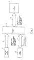
- the audio-visual system illustrated block schematically comprises a television receiver 1 which serves as a visual display unit of the system, a video recorder 2 and a satellite receiver or computer 3.
- the television receiver 1, video recorder 2 and the satellite receiver or computer 3 are fitted with the socket parts of standard connectors (i.e. so-called SCART or Peritel connector) hereinbefore described.
- SCART or Peritel connector standard connectors
- the plug parts of these connectors are received by the socket parts and have the contact pins thereof connected to specific conductors of standard cordsets indicated schematically at 4,5 and 6.
- the audio-visual system includes an electric switching arrangement 7 provided with the socket parts of three European standard connectors which receive the plug parts of the connectors which will be fitted to the ends of the standard cordsets 4,5 and 6 incoming to the electric switching arrangement 7.
- the switching arrangement 7 serves for selectively interconnecting the television receiver 1, video recorder 2 and satellite or computer 3, as appropriate, in dependence upon the user's requirements.
- Such selective switching which is achieved by the use of a logic circuit enables the requisite interconnections between system component units to be made without the need for the provision of additional standard connectors at the television receiver and video recorder and is therefore ideally suited for use with many existing television receivers and video recorders fitted with single European standard connectors.
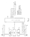
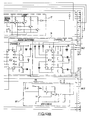
- the switching arrangement comprises socket parts 8,9 and 10 of European standard connectors. It may here be mentioned that the numerals contained within the blocks 8,9 and 10 indicate the dedicated socket contact numbers of such standard connectors, as will be well understood by those skilled in the art.
- the electronic switching arrangement also comprises a video recorder status circuit 11 which is connected to a logic circuit 12 and which detects the status (e.g. play, record etc.) and gives priority to the recorder 2 ( Figure 1), if necessary.
- the logic circuit 12 may also receive an input from an operative signal processor 13 connected to the satellite 3 ( Figure 1) through the standard connector socket part 10.
- the logic circuit 12 is designed to provide a switching command signal based on information derived from the video status circuit 11 and the signal processor 13. This command signal is applied to an electric switching circuit 14 which accordingly operates to establish the appropriate interconnections between component units of the system in order to meet the users' demands or requirements and also takes into account any priority requirement which requires another indicated requirement to be overridden.
- logic options 5,7,8,9 and 10 these can be provided by the signal and switching connections indicated in Figures 7,8,9,10 and 11, respectively.
- the television receiver is operated in the audio-visual mode.
- the video recorder 2 and a satellite receiver or (computer) 3 signal source is to be selected.
- signal source is meant the composite video and dual channel audio signals available as outputs at the SCART connector sockets of the equipment.
- RGB component signals from BSB satellite equipment or from some brands of computer will be displayed on the television receiver when the switching protocol as above permits. However, RGB component signals cannot be recorded.
- Composite video signal or RGB signals are indicated in the SCART protocol by a status voltage present or absent on pin 8 of the SCART connector and a fast blanking signal present or absent on pin 16 of the connector.
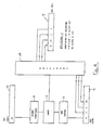
- the switching arrangement illustrated includes video and audio (channels A and B) switching circuits 15 and 16, respectively. These circuits consist of electric switches controlled by output signals from the logic circuit arrangement including two logic circuits 17 and 18 which are designed to interpret the presence of and status of various signals provided by the component circuits connectible by the switching arrangement.
- the switching arrangement also includes a video status circuit 19 which determines the priority given to the inputs on the connecting socket AV3.
- a signal processor 20 determines without ambiguity the presence of a composite video signal at the connecting socket AV1.
- the switching arrangement has to route independently the composite video and channel A and channel B audio signals.
- AV2 is required to receive either the AV1 or AV3 signals.
- AV3 is required to receive either the AV1 or AV2 signals.
- This logic is illustrated diagrammatically as requiring six changeover switches arranged in pairs as shown in Figure 12 of the drawings. All the operating requirements can then be met by common switching logic to each pair.
- VCR's provide a status signal on pin 8 of the Peritel (SCART) connector.
- SCART Peritel
- the VCR video recorder
- the satellite receiver can be ON or OFF thereby creating the following tables of logic state:
- the logic for switch A (channel A) is AV1.VCR - a two input AND gate.
- the logic for switch B (channel B) is AV1 status output logic.
- the VCR status circuit (AV3 Status Detection) 19 comprises transistors T17, T18 and T19.
- pin 8 of connector AV3 is logic high, transistor T19 is turned on which in turn turns transistor T17 off. This causes pin 8 of AV2 to be pulled logic high by the circuit of resistor R56 and diode D3. This has the action of putting a suitable television receiver into the A.V mode.
- transistor T18 is also turned off putting a logic high on pin 10 of IC1 via resistor R55.
- transistor T19 is turned off putting transistors T17 and T18 on. This has the action of turning off diode D3 releasing pin 8 of AV2 from influence by the VCR status circuit 19 and putting a logic low on pin 10 of integrated circuit IC1 via resistor R55.
- the signal processor circuit 20 (AV1 Status Detection) comprises transistors T1, T2 and T3.
- T1 When a video signal is present on pin 20 of AV1 transistor, T1 is biased to favourably amplify the sync pulse section of that signal irrespective of the video content.
- Transistor T2 is an emitter follower to isolate the function of transistor T1 from the following circuitry.
- Transistor T3 is then biased such that only sync pulses appear at its collector over a wide range of varying amplitude of video content.
- Resistor R6 and capacitor C3 filter H.F. noise and resistor R8 and capacitor C4 extend the range over which automatic biasing functions.
- the stable negative going sync pulses at the collector of transistor T3 are D.C. restored to ground by the action of capacitor C5 and diode D1.
- a substantially stable positive D.C. potential is stored on capacitor C6 as a direct result of the presence of a composite video signal on pin 20 of AV1.
- the logic circuits 17 and 18 comprise transistors T4, T5, T6, T7 and T15, T16.
- Transistor T4 performs the function of inverting the AV1 status signal giving AV1 status logic.
- Transistor T4 drives into three inverting buffer transistors T5, T6 and T7 which provide the AV1 status logic.
- Transistor T5 drives pin 15 of integrated circuit IC1 and determines the video route from pin 3 to pin 16 (pin 15 high) or pin 1 to pin 16 (pin 15 low) .
- Transistor T6 drives pin 9 of integrated circuit IC2 and pin 9 of integrated circuit IC3 and determines the audio channel route from pin 3 to pin 4 (pin 9 high) or pin 5 to pin 4 (pin 9 low).
- Transisistor T7 via diode D2 pulls pin 8 on AV2 high to pull the TV connected to AV2 socket into the A.V mode provided the television receiver is designed to do so otherwise the user switches the television receiver to A.V mode.
- the AV1 logic on the collector of transistor T4 is also connected via resistor R22 to pin 8 of circuit IC1, defining one input of an OR gate.
- the other input of this OR gate is pin 10 which receives AV3 status logic from transistor T18 via resistor R55.
- the logic output of the OR gate of circuit IC1 is pin 9 which drives pin 12 of circuit IC1 directly and pin 10 of circuit IC2 and pin 10 of circuit IC3 via a double inverting buffer consisting of the transistors T15 and T16 which ensure the correct switching level.
- pin 12 of circuit IC1 determines the video route from pin 5 to pin 13 (pin 12 high) or pin 4 to pin 13 (pin 12 low).
- pins 10 of integrated circuits IC2 and IC3 determines the audio channel route from pin 1 to pin 15 (pin 10 high) or pin 2 to pin 15 (pin 10 low).
- the RGB source circuit will be directly connected between pins 7, 11 and 13 of connector AV1 (SKT3 SAT) and AV2 (SKT4 TV) for conveyance of Red, Green and Blue component signals.
- the associated fast blanking signal present on pin 16 of AV1 (SKT3 SAT) is connected to pin 6 of circuit IC1.
- the status of pin 10 of circuit IC1 determines the fast blanking route from pin 6 to pin 11 (pin 10 low).
- Pin 10 logic is controlled by the VCR status signal derived from the collector of transistor T8 via resistor R55.
Applications Claiming Priority (2)
| Application Number | Priority Date | Filing Date | Title |
|---|---|---|---|
| GB9102102A GB2254512A (en) | 1991-01-31 | 1991-01-31 | Selectively interconnecting units in audio-visual systems |
| GB9102102 | 1991-01-31 |
Publications (1)
| Publication Number | Publication Date |
|---|---|
| EP0507433A1 true EP0507433A1 (de) | 1992-10-07 |
Family
ID=10689310
Family Applications (1)
| Application Number | Title | Priority Date | Filing Date |
|---|---|---|---|
| EP92300813A Withdrawn EP0507433A1 (de) | 1991-01-31 | 1992-01-30 | Verbesserungen in Bezug auf audiovisuelle Systeme |
Country Status (2)
| Country | Link |
|---|---|
| EP (1) | EP0507433A1 (de) |
| GB (1) | GB2254512A (de) |
Cited By (10)
| Publication number | Priority date | Publication date | Assignee | Title |
|---|---|---|---|---|
| EP0565170A2 (de) * | 1992-04-08 | 1993-10-13 | Koninklijke Philips Electronics N.V. | Anordnung zum Gebrauch in einem System zur Verbindung von Geräten |
| EP0626787A2 (de) * | 1993-05-26 | 1994-11-30 | Koninklijke Philips Electronics N.V. | Videorekorder |
| EP0705032A1 (de) | 1994-09-28 | 1996-04-03 | Philips Electronique Grand Public | Umschaltvorrichtung für ein Fernsehgerät |
| US5594551A (en) * | 1992-11-20 | 1997-01-14 | Matsushita Electric Industrial Co., Ltd. | Method and apparatus for selectively recording multiple television signals |
| EP1237359A2 (de) * | 2001-02-20 | 2002-09-04 | Pace Micro Technology Ltd | Handfernbedienung |
| EP1271945A2 (de) * | 2001-06-21 | 2003-01-02 | Samsung Electronics Co., Ltd. | Videsignal-Erzeugungsanlage |
| EP1353328A2 (de) * | 2002-04-11 | 2003-10-15 | Samsung Electronics Co., Ltd. | Vorrichtung zur Wiedergabe eines Aufnahmemediums |
| EP1280154A3 (de) * | 2001-07-28 | 2006-05-10 | Samsung Electronics Co., Ltd. | Kombinierter DVD Spieler und Videorekorder |
| EP1437884A3 (de) * | 2003-01-11 | 2007-08-22 | Samsung Electronics Co., Ltd. | SCART Ausgabevorrichtung und -verfahren |
| FR2910217A1 (fr) * | 2006-12-14 | 2008-06-20 | St Microelectronics Sa | Cellule de detection video |
Families Citing this family (2)
| Publication number | Priority date | Publication date | Assignee | Title |
|---|---|---|---|---|
| GB2266637B (en) * | 1992-04-30 | 1996-03-06 | Charles Robert Bodle | Audio and video switching apparatus |
| GB2411064A (en) * | 2004-01-23 | 2005-08-17 | Chris Skelton | Video switching device |
Citations (3)
| Publication number | Priority date | Publication date | Assignee | Title |
|---|---|---|---|---|
| FR2583945A1 (fr) * | 1985-06-21 | 1986-12-26 | Parriaux Roland | Dispositif de connexion de peripheriques a un televiseur avec selection |
| FR2613163A1 (fr) * | 1987-03-24 | 1988-09-30 | Rs 80 | Boitier de commutation pour televiseur |
| JPH02183484A (ja) * | 1988-09-02 | 1990-07-18 | Sanyo Electric Co Ltd | ビデオテープレコーダ |
-
1991
- 1991-01-31 GB GB9102102A patent/GB2254512A/en not_active Withdrawn
-
1992
- 1992-01-30 EP EP92300813A patent/EP0507433A1/de not_active Withdrawn
Patent Citations (3)
| Publication number | Priority date | Publication date | Assignee | Title |
|---|---|---|---|---|
| FR2583945A1 (fr) * | 1985-06-21 | 1986-12-26 | Parriaux Roland | Dispositif de connexion de peripheriques a un televiseur avec selection |
| FR2613163A1 (fr) * | 1987-03-24 | 1988-09-30 | Rs 80 | Boitier de commutation pour televiseur |
| JPH02183484A (ja) * | 1988-09-02 | 1990-07-18 | Sanyo Electric Co Ltd | ビデオテープレコーダ |
Non-Patent Citations (2)
| Title |
|---|
| IEE PROCEEDINGS SECTION A A I, vol. 129, no. 7, part A, September 1982, pages 493-506; J.C. MacKELLAR: "Television receiver design" * |
| PATENT ABSTRACTS OF JAPAN, vol. 14, no. 465 (P-1114), 9th October 1990; & JP-A-2 183 484 (SANYO) 18-07-1990 * |
Cited By (19)
| Publication number | Priority date | Publication date | Assignee | Title |
|---|---|---|---|---|
| EP0565170A2 (de) * | 1992-04-08 | 1993-10-13 | Koninklijke Philips Electronics N.V. | Anordnung zum Gebrauch in einem System zur Verbindung von Geräten |
| EP0565170A3 (en) * | 1992-04-08 | 1993-11-10 | Koninkl Philips Electronics Nv | Apparatus for use in a system for interconnecting appliances |
| EP0859510A1 (de) * | 1992-04-08 | 1998-08-19 | Koninklijke Philips Electronics N.V. | Videoverbindungssystem |
| US5594551A (en) * | 1992-11-20 | 1997-01-14 | Matsushita Electric Industrial Co., Ltd. | Method and apparatus for selectively recording multiple television signals |
| US5668785A (en) * | 1992-11-20 | 1997-09-16 | Matsushita Electric Industrial Co., Ltd. | Multiple audio signal recording and reproducing apparatus |
| EP0626787A2 (de) * | 1993-05-26 | 1994-11-30 | Koninklijke Philips Electronics N.V. | Videorekorder |
| EP0626787A3 (de) * | 1993-05-26 | 1995-05-24 | Philips Electronics Nv | Videorekorder. |
| EP0705032A1 (de) | 1994-09-28 | 1996-04-03 | Philips Electronique Grand Public | Umschaltvorrichtung für ein Fernsehgerät |
| EP1237359A2 (de) * | 2001-02-20 | 2002-09-04 | Pace Micro Technology Ltd | Handfernbedienung |
| EP1237359A3 (de) * | 2001-02-20 | 2004-01-07 | Pace Micro Technology Ltd | Handfernbedienung |
| EP1271945A2 (de) * | 2001-06-21 | 2003-01-02 | Samsung Electronics Co., Ltd. | Videsignal-Erzeugungsanlage |
| EP1271945A3 (de) * | 2001-06-21 | 2006-12-13 | Samsung Electronics Co., Ltd. | Videsignal-Erzeugungsanlage |
| EP1280154A3 (de) * | 2001-07-28 | 2006-05-10 | Samsung Electronics Co., Ltd. | Kombinierter DVD Spieler und Videorekorder |
| EP1353328A2 (de) * | 2002-04-11 | 2003-10-15 | Samsung Electronics Co., Ltd. | Vorrichtung zur Wiedergabe eines Aufnahmemediums |
| EP1353328A3 (de) * | 2002-04-11 | 2004-10-06 | Samsung Electronics Co., Ltd. | Vorrichtung zur Wiedergabe eines Aufnahmemediums |
| US7136569B2 (en) | 2002-04-11 | 2006-11-14 | Samsung Electronics Co., Ltc. | Combination system having a plurality of reproducing apparatuses and a method for controlling operation thereof |
| EP1437884A3 (de) * | 2003-01-11 | 2007-08-22 | Samsung Electronics Co., Ltd. | SCART Ausgabevorrichtung und -verfahren |
| FR2910217A1 (fr) * | 2006-12-14 | 2008-06-20 | St Microelectronics Sa | Cellule de detection video |
| US8346982B2 (en) | 2006-12-14 | 2013-01-01 | Stmicroelectronics S.A. | Video detection cell for a set top box |
Also Published As
| Publication number | Publication date |
|---|---|
| GB9102102D0 (en) | 1991-03-13 |
| GB2254512A (en) | 1992-10-07 |
Similar Documents
| Publication | Publication Date | Title |
|---|---|---|
| US6169879B1 (en) | System and method of interconnecting and using components of home entertainment system | |
| US4334242A (en) | Remote control television with external data bus connection | |
| US7398540B1 (en) | System and method for tuning channels using a central point of control | |
| KR0148018B1 (ko) | 텔레비젼 신호 스위칭 시스템 | |
| EP0392552B1 (de) | Tonumschaltung für ein Ton/Videosystem mit S-Videofähigkeit | |
| US4783846A (en) | Switchable signal source module for use with cable television converter | |
| EP0507433A1 (de) | Verbesserungen in Bezug auf audiovisuelle Systeme | |
| US4647973A (en) | Switch apparatus for a video interconnection system | |
| FI76905B (fi) | Mellankopplingsanordning foer videokomponenter. | |
| JP3420792B2 (ja) | 相互連結システムに用いるための装置 | |
| JPS61502708A (ja) | オ−デイオ−ビジユアル機器用のオ−デイオ/ビデオアダプタ | |
| US4789905A (en) | Output signal switching circuit for a video tape recorder | |
| EP0565170B1 (de) | Anordnung zum Gebrauch in einem System zur Verbindung von Geräten | |
| EP0447933A1 (de) | Kommunikationssystem für Farbfernsehsignale | |
| JPS6132673A (ja) | テレビジヨン受信機 | |
| GB2266637A (en) | Audio and video switching apparatus | |
| JP3006062B2 (ja) | 電子機器におけるステレオ入力装置 | |
| JPH079272Y2 (ja) | ビデオプレーヤ | |
| KR100256383B1 (ko) | 텔레비젼 수상기와 주변기기 사이의 접속 장치 | |
| US6212326B1 (en) | Video tape or cassette recorder | |
| US5262859A (en) | Video signal transmitter/receiver | |
| JPS6329341Y2 (de) | ||
| JP2001057657A (ja) | 信号入出力制御装置 | |
| KR960007568B1 (ko) | 위성방송 수신기의 디코더용 콘넥터를 비디오 카세트 레코더와 공용하기 위한 스위칭 회로 | |
| KR920004340Y1 (ko) | 텔레비젼 신호용의 전환스위치 |
Legal Events
| Date | Code | Title | Description |
|---|---|---|---|
| PUAI | Public reference made under article 153(3) epc to a published international application that has entered the european phase |
Free format text: ORIGINAL CODE: 0009012 |
|
| AK | Designated contracting states |
Kind code of ref document: A1 Designated state(s): AT BE CH DE DK ES FR GB GR IT LI LU NL PT SE |
|
| RAP1 | Party data changed (applicant data changed or rights of an application transferred) |
Owner name: ZOOGONY LIMITED |
|
| STAA | Information on the status of an ep patent application or granted ep patent |
Free format text: STATUS: THE APPLICATION IS DEEMED TO BE WITHDRAWN |
|
| 18D | Application deemed to be withdrawn |
Effective date: 19930408 |