EP0495569A2 - Stray light trap in a monochromator - Google Patents
Stray light trap in a monochromator Download PDFInfo
- Publication number
- EP0495569A2 EP0495569A2 EP92300078A EP92300078A EP0495569A2 EP 0495569 A2 EP0495569 A2 EP 0495569A2 EP 92300078 A EP92300078 A EP 92300078A EP 92300078 A EP92300078 A EP 92300078A EP 0495569 A2 EP0495569 A2 EP 0495569A2
- Authority
- EP
- European Patent Office
- Prior art keywords
- light
- monochromator
- stray light
- characteristic
- absorbing
- Prior art date
- Legal status (The legal status is an assumption and is not a legal conclusion. Google has not performed a legal analysis and makes no representation as to the accuracy of the status listed.)
- Ceased
Links
- 238000001228 spectrum Methods 0.000 claims description 4
- 238000000034 method Methods 0.000 claims 5
- 238000010521 absorption reaction Methods 0.000 claims 1
- 238000005119 centrifugation Methods 0.000 claims 1
- 230000003287 optical effect Effects 0.000 abstract description 5
- 230000007246 mechanism Effects 0.000 description 4
- 230000005855 radiation Effects 0.000 description 4
- 238000004458 analytical method Methods 0.000 description 2
- 239000011248 coating agent Substances 0.000 description 2
- 238000000576 coating method Methods 0.000 description 2
- 238000002798 spectrophotometry method Methods 0.000 description 2
- 238000002835 absorbance Methods 0.000 description 1
- 230000003321 amplification Effects 0.000 description 1
- 238000007743 anodising Methods 0.000 description 1
- 230000001427 coherent effect Effects 0.000 description 1
- 230000000295 complement effect Effects 0.000 description 1
- 230000003292 diminished effect Effects 0.000 description 1
- 239000011521 glass Substances 0.000 description 1
- 238000009434 installation Methods 0.000 description 1
- 238000004519 manufacturing process Methods 0.000 description 1
- 239000000463 material Substances 0.000 description 1
- 239000000203 mixture Substances 0.000 description 1
- 230000004048 modification Effects 0.000 description 1
- 238000012986 modification Methods 0.000 description 1
- 238000003199 nucleic acid amplification method Methods 0.000 description 1
- 230000009467 reduction Effects 0.000 description 1
- 230000007704 transition Effects 0.000 description 1
Images
Classifications
-
- G—PHYSICS
- G01—MEASURING; TESTING
- G01J—MEASUREMENT OF INTENSITY, VELOCITY, SPECTRAL CONTENT, POLARISATION, PHASE OR PULSE CHARACTERISTICS OF INFRARED, VISIBLE OR ULTRAVIOLET LIGHT; COLORIMETRY; RADIATION PYROMETRY
- G01J3/00—Spectrometry; Spectrophotometry; Monochromators; Measuring colours
- G01J3/02—Details
- G01J3/0262—Constructional arrangements for removing stray light
-
- G—PHYSICS
- G02—OPTICS
- G02B—OPTICAL ELEMENTS, SYSTEMS OR APPARATUS
- G02B5/00—Optical elements other than lenses
-
- G—PHYSICS
- G01—MEASURING; TESTING
- G01N—INVESTIGATING OR ANALYSING MATERIALS BY DETERMINING THEIR CHEMICAL OR PHYSICAL PROPERTIES
- G01N2201/00—Features of devices classified in G01N21/00
- G01N2201/06—Illumination; Optics
- G01N2201/064—Stray light conditioning
- G01N2201/0642—Light traps; baffles
Definitions
- the present invention relates to the production of monochromatic light, and in particular relates to a monochromator for use in an analytical centrifuge.
- a monochromator is a device used to supply a collimated beam of light having some desired, narrow range of wavelengths.
- a monochromator typically has the following component parts: (1) an entrance slit with a source of radiation of a wide range of wavelengths; (2) a prism or diffraction grating dispersing the incident radiation into a continuous spectrum of wavelengths; (3) some mechanism to rotate the prism or grating so the desired spectrum of radiation is obtained; and (4) an exit slit selectively isolating a narrow band of wavelengths.
- a detector is positioned at the monochromator exit for detecting the radiation antennuation of a sample placed between the exit and the detector. Appropriate signal amplification circuit is provided in conjunction with the detector.
- the present invention is directed to a monochromator which substantially reduces the stray light component in the monochromator output.
- the monochromator has internal wall features that are designed to capture stray light, so that the stray light does not reflect or scatter back to the diffraction grating or mix in with the monochromator output.
- surfaces with different optical characteristics are strategically positioned along the internal walls of the light tube in a manner which will either absorb incident stray light and/or reflect stray light in a direction away from the diffraction grating and the exit of the monochromator.
- light absorbing surfaces with three different characteristics are provided. Some of the surfaces are very smooth reflective semi-absorbing, some are semi-smooth reflective semi-absorbing, and some are rough scattering, highly absorbing. The placements of the surfaces at selected locations and orientations causes stray light to be trapped away from the diffraction grating and the exit of the monochromator.
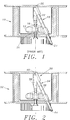
- Fig.1 depicts an analytical centrifuge having a prior art monochromator.
- Fig. 2 illustrates an analytical centrifuge having a monochromator in accordance with one embodiment of the present invention.
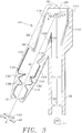
- Fig. 3 is an internal view of the monochromator showing the locations of the surfaces with different optical characteristics.
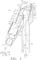
- Fig. 4 illustrates stray light trapping in a region near the diffraction mirror.
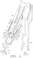
- Fig. 5 illustrates stray light trapping in a region near the monochromator exit.
- a monochromator 30 according to one embodiment of the present invention in an analytical centrifuge 32 is illustrated.
- the set up of the monochromator 30 with respect to the centrifuge 32 is similar to those described in U.S. Patent Nos. 4,830,493; 4,919,537 and 4,921,350 which have been incorporated by reference herein.
- the design of the light tube 34 of the monochromator 30 is significantly different in that the light tube 34 is structured to trap stray light.
- the inside of the light tube 34 of the monochromator 30 is illustrated in simplified form.
- the light tube 34 is made up to two segments 36 and 38 coupled at an elbow 39 in which a diffraction mirror 40 is disposed.
- Some structures have been omitted for clarity, the details of which are found in U.S. Patent Nos. 4,830,493; 4,919,537 and 4,921,350.
- the mirror 40 has a diffraction grating ruled on its surface.
- the mirror 40 is shaped about one axis (along the plane of Fig.3) for the generation of collimated light.
- the cross-section of the segment 36 is round and that of the segment 38 is rectangular.
- Incident light 50 from a light source 44 directed at the mirror 40 diffracts into coherent light of different wavelengths including 0, 1, and higher order components.
- the mirror 40 is provided with a varying curvature and varying spaced rulings so that tilting of the mirror 40 selectively directs light of a particular wavelength range through the exit end 42 of the light tube segment 38 towards the sample.
- An exit slit 48 is used to selectively isolate a narrow band of the light emerging from the exit end 42.
- a motor coupled with a gear mechanism are provided to tilt the mirror 40 between two extreme positions A and B as shown in Fig.3.
- the internal structure of the light tube 34 of the present invention is designed so that it does not reflect or scatter back stray light to the mirror 40 and cause re-diffraction at the wrong wavelength.
- the internal structure is designed also to prevent stray light from mixing with the exit light. This results in the light at the wavelength of interest passing through the monochromator to have very little stray light.
- the wavelength of interest is in the 1 or -1 order.
- the zero order wavelength is typically not used for spectrophotometric studies because of too high intensity and polychromatic. Higher order wavelengths are also not of interest because of possible confusion (overlap) with the primary order wavelengths.
- the inner surface of the light tube 34 is finished or otherwise lined with materials of certain optical characteristics.
- the surfaces have one of three characteristics: (1) very smooth reflective semi-absorbing, (2) semi-smooth reflective semi-absorbing, and (3) rough scattering highly absorbing.
- the first type of surface can be obtained by lining the inside of the light tube 34 using absorptive glass, Cat-A-Lac Gloss or Parson's Black surfaces.
- the second type of surface can be obtained by black anodising the smooth machined inside surface of the light tube 34.
- the third type of surface can be obtained by coating the inside surface of the light tube 34 using a special "optical black" coating developed by Martin Marietta Aerospace Corp.
- the surfaces having the respective characteristics are strategically positioned along the inner walls of the light tube 34 as shown in Fig.3. Generally, the surfaces nearer the mirror 40 have the first characteristic. Further down the segment 38 of the light tube 34 are positioned the surfaces having the third characteristic. Surfaces having the second characteristic are found near the exit end of the segment and any other surfaces not having the first and second characteristics. Because the diffracted light from the mirror is collimated parallel to the plane of Fig.3, the side walls (parallel to plane of Fig. 3) of the rectangular section of the segment 38 (including the elbow portion having surfaces 112 and 114) are exposed to very little stray light and thus can be left as machined surfaces or made to possess the second characteristic.
- the surfaces (flat) 110, 112, 114 and 116 with a high view factor of the diffraction grating mirror 40 have the first characteristic so as to minimize scattering and provide controlled reflection, as will become clear in the discussion below.
- the first characteristic about 10% of incident light is reflected, 0.5% of incident light is diffusely scattered, and the rest of the light is absorbed.
- Such surfaces absorb reflected light and/or diffusely scatter light but not to the mirror because of the absence of view factor to the mirror.
- the general characteristics of the third type of surfaces are reflectance of less than 0.5% over the entire visible region (400-700nm) and less than 0.8% from 300 to 900nm, and light absorbance over a large spectrum (0.27 to 20 microns).
- the rest of the surfaces e.g. 130, 132 etc. near the exit end 42 of the segment 38 which are exposed to light very near the wavelength of interest have the second characteristic.
- some of the surfaces protrude towards the axis of the segment 38.
- the protruding surfaces defines a clearance for passage of light 46 of the desired wavelength reflected from the diffraction mirror 40.
- stray light trapping mechanism of the surfaces will be described separately in Figs. 4 and 5.
- the zero order white light component of stray light is of particular concern because of its high intensity.
- the particular orientation of the mirror 40 between positions A and B would not affect the analysis of the stray light trapping mechanism.
- the light rays shown in the figures are only representative of the paths of light reflected from the mirror 40. The analysis is applicable to all order of light rays reflected from the mirror 40 at any mirror orientation.
- the zero order ray 52 reflects off of surface 114 which is positioned such that the reflected ray 54 misses the mirror 40 before reaching surface 116.
- the ray 54 is reflected off of surface 116 in a ray 56 towards surface 120.
- About 10% of incident light is reflected at the surfaces 114 and 116.
- About 0.5% of incident light on surfaces 114 and 116 is diffusely scattered.
- the rest of the incident light is absorbed by these surfaces.
- the ray 56 is about 1% of the incident ray 52 diffracted from the mirror 40. This 1% of light after being absorbed by highly absorbing surface 120 will have very little light intensity.
- Other light rays from mirror 40 directed at surface 114 will follow a somewhat similar path leading to a substantial reduction of intensity.
- the ray 58 which is directed at surface 112 just beyond surface 114 is reflected along ray 60 and clears the mirror 40 before being reflected at surface 116.
- the reflected ray continues to be reflected between the surfaces 112 and 116, wherein the intensity of the stray light is reduced by 90% each time it is reflected off the surfaces 112 and 116.
- the surface 112 is set at a slightly diverging angle to surface 116, so that the multiple reflections do not converge back to the mirror.
- the transition point between surfaces 114 and 112 is determined by letting the ray 58 just clear the mirror.
- Other rays from the mirror 40 to the surface 112 will also experience multiple reflections, except beyond ray 62 which is reflected at surface 112 to the surface 121 (ray 64).
- the high absorbing surface 121 substantially absorbs the intensity of ray 64.
- Ray 66 is reflected at surface 112 to the inner walls of the light tube segment 36. The multiple reflections occurring in the segment will substantially diminish the stray light
- Stray light 67 from the mirror 40 is reflected at surface 116 to surface 121 (ray 68) and to surface 122 (ray 69) which is substantially absorbed.
- Stray light ray 70 is reflected at surface 110 to surface 122. Any diffuse scattering from surface 122 does not affect the mirror 40 since surface 122 does not have a view factor to the mirror 40. In any event, the diffusely scattered stray light from surface 122 is of low intensity which is further diminished when the scattered light reaches the adjacent light absorbing surfaces. To maintain the clarity of Fig. 4, the reflected or scattered low intensity light rays are not shown in the figure.
- stray light trapped at the lower end of the segment 38 is now discussed.
- Ray 71 from mirror 40 is reflected at surface 130 to surface 122 where the light is substantially absorbed.
- ray 74 is reflected at surface 132 to surface 124 (ray 76) and absorbed.
- the light rays 78 and 80 which are very near the wavelength of interest (ray 46) are respectively reflected at surfaces 138 and 140 to surfaces 134 and 136, respectively.
- the protrusions of surfaces 134 and 136 keep light from reflecting back to the diffraction mirror 40.
- an incident light detector 82 can be placed at the shoulder defined between surfaces 116 and 122 to receive light ray 84 reflected from surface 140.
- This reflected light provides a reference light intensity at a wavelength very close to the desired wavelength of ray 46 for the spectrophotometric analysis.
- the protruding corners of surfaces 134, 136, 138 and 140, and corners 142 and 144 shield the mirror 40 from the light rays 90 and 92 reflected from the window 150 of the sample cell in the rotor. These corners also shields the incident detector 82 from light reflected from the window 150.
- the surfaces may be substituted with surfaces of other characteristics which can also accomplish the same stray light trapping tasks e.g. substituting the third type of surfaces for the second type, except that the third type of surfaces are more expensive to make. Accordingly, it is to be understood that the invention is not to be limited by the specific illustrated embodiments, but only by the scope of the appended claims.
Landscapes
- Physics & Mathematics (AREA)
- Spectroscopy & Molecular Physics (AREA)
- General Physics & Mathematics (AREA)
- Optics & Photonics (AREA)
- Spectrometry And Color Measurement (AREA)
- Optical Measuring Cells (AREA)
Abstract
Description
- The present invention relates to the production of monochromatic light, and in particular relates to a monochromator for use in an analytical centrifuge.
- The following United States Patents are incorporated by reference herein: 4,830,493; 4,919,537; and 4,921,350. These patents were issued to the inventor of the present invention and were commonly assigned to Beckman Instruments, Inc., the assignee of the present invention. The patents describe monochromators designed for use in analytical centrifuges.
- A monochromator is a device used to supply a collimated beam of light having some desired, narrow range of wavelengths. A monochromator typically has the following component parts: (1) an entrance slit with a source of radiation of a wide range of wavelengths; (2) a prism or diffraction grating dispersing the incident radiation into a continuous spectrum of wavelengths; (3) some mechanism to rotate the prism or grating so the desired spectrum of radiation is obtained; and (4) an exit slit selectively isolating a narrow band of wavelengths. For spectrophotometry studies, a detector is positioned at the monochromator exit for detecting the radiation antennuation of a sample placed between the exit and the detector. Appropriate signal amplification circuit is provided in conjunction with the detector.
- referring to Fig.1, the arrangement of a prior art monochromator in an analytical centrifuge as
- The present invention is directed to a monochromator which substantially reduces the stray light component in the monochromator output. The monochromator has internal wall features that are designed to capture stray light, so that the stray light does not reflect or scatter back to the diffraction grating or mix in with the monochromator output.
- According to the present invention, surfaces with different optical characteristics are strategically positioned along the internal walls of the light tube in a manner which will either absorb incident stray light and/or reflect stray light in a direction away from the diffraction grating and the exit of the monochromator. In the described embodiment, light absorbing surfaces with three different characteristics are provided. Some of the surfaces are very smooth reflective semi-absorbing, some are semi-smooth reflective semi-absorbing, and some are rough scattering, highly absorbing. The placements of the surfaces at selected locations and orientations causes stray light to be trapped away from the diffraction grating and the exit of the monochromator.
- Fig.1 depicts an analytical centrifuge having a prior art monochromator.
- Fig. 2 illustrates an analytical centrifuge having a monochromator in accordance with one embodiment of the present invention.
- Fig. 3 is an internal view of the monochromator showing the locations of the surfaces with different optical characteristics.
- Fig. 4 illustrates stray light trapping in a region near the diffraction mirror.
- Fig. 5 illustrates stray light trapping in a region near the monochromator exit.
- The following description is of the best presently contemplated mode of carrying out the invention. This description is made for the purpose of illustrating the general principles of the invention and should not be taken in a limiting sense. The scope of the invention is best determined by reference to the appended claims.
- Referring to Fig.2, the installation of a
monochromator 30 according to one embodiment of the present invention in ananalytical centrifuge 32 is illustrated. The set up of themonochromator 30 with respect to thecentrifuge 32 is similar to those described in U.S. Patent Nos. 4,830,493; 4,919,537 and 4,921,350 which have been incorporated by reference herein. However, the design of thelight tube 34 of themonochromator 30 is significantly different in that thelight tube 34 is structured to trap stray light. - Referring to Fig.3, the inside of the
light tube 34 of themonochromator 30 is illustrated in simplified form. Thelight tube 34 is made up to twosegments elbow 39 in which adiffraction mirror 40 is disposed. Some structures have been omitted for clarity, the details of which are found in U.S. Patent Nos. 4,830,493; 4,919,537 and 4,921,350. Similar to the monochromators described in the patents, themirror 40 has a diffraction grating ruled on its surface. Themirror 40 is shaped about one axis (along the plane of Fig.3) for the generation of collimated light. The cross-section of thesegment 36 is round and that of thesegment 38 is rectangular.Incident light 50 from alight source 44 directed at themirror 40 diffracts into coherent light of different wavelengths including 0, 1, and higher order components. About another axis (perpendicular to the plane of Fig. 3), themirror 40 is provided with a varying curvature and varying spaced rulings so that tilting of themirror 40 selectively directs light of a particular wavelength range through theexit end 42 of thelight tube segment 38 towards the sample. Anexit slit 48 is used to selectively isolate a narrow band of the light emerging from theexit end 42. A motor coupled with a gear mechanism (not shown) are provided to tilt themirror 40 between two extreme positions A and B as shown in Fig.3. - Because the
mirror 40 diffracts light at wavelengths not of interest (stray light) in different directions parallel to the plane of Fig.3, the internal structure of thelight tube 34 of the present invention is designed so that it does not reflect or scatter back stray light to themirror 40 and cause re-diffraction at the wrong wavelength. The internal structure is designed also to prevent stray light from mixing with the exit light. This results in the light at the wavelength of interest passing through the monochromator to have very little stray light. Typically, the wavelength of interest is in the 1 or -1 order. The zero order wavelength is typically not used for spectrophotometric studies because of too high intensity and polychromatic. Higher order wavelengths are also not of interest because of possible confusion (overlap) with the primary order wavelengths. - To accomplish stray light trapping, the inner surface of the
light tube 34 is finished or otherwise lined with materials of certain optical characteristics. In the illustrated embodiment, the surfaces have one of three characteristics: (1) very smooth reflective semi-absorbing, (2) semi-smooth reflective semi-absorbing, and (3) rough scattering highly absorbing. The first type of surface can be obtained by lining the inside of thelight tube 34 using absorptive glass, Cat-A-Lac Gloss or Parson's Black surfaces. The second type of surface can be obtained by black anodising the smooth machined inside surface of thelight tube 34. The third type of surface can be obtained by coating the inside surface of thelight tube 34 using a special "optical black" coating developed by Martin Marietta Aerospace Corp. It has been found that for the three types of surfaces, light back scatter ten times less for the first type of surface as compared to the third type of surface, and the third type is ten times less than the second type of surface. The first type of surface, however, does have the highest reflected intensity at the complementary angle. - The surfaces having the respective characteristics are strategically positioned along the inner walls of the
light tube 34 as shown in Fig.3. Generally, the surfaces nearer themirror 40 have the first characteristic. Further down thesegment 38 of thelight tube 34 are positioned the surfaces having the third characteristic. Surfaces having the second characteristic are found near the exit end of the segment and any other surfaces not having the first and second characteristics. Because the diffracted light from the mirror is collimated parallel to the plane of Fig.3, the side walls (parallel to plane of Fig. 3) of the rectangular section of the segment 38 (including the elbowportion having surfaces 112 and 114) are exposed to very little stray light and thus can be left as machined surfaces or made to possess the second characteristic. Specifically, the surfaces (flat) 110, 112, 114 and 116 with a high view factor of the diffraction grating mirror 40 (ie ratio of direct view to the mirror and direct view to other structures), or that receive zero order light, have the first characteristic so as to minimize scattering and provide controlled reflection, as will become clear in the discussion below. For the first type of surfaces, about 10% of incident light is reflected, 0.5% of incident light is diffusely scattered, and the rest of the light is absorbed.Surfaces - As can be seen in Fig. 3, along the
second segment 38 of the light tube, some of the surfaces (e.g. 110, 116) protrude towards the axis of thesegment 38. The protruding surfaces defines a clearance for passage oflight 46 of the desired wavelength reflected from thediffraction mirror 40. - The stray light trapping mechanism of the surfaces will be described separately in Figs. 4 and 5. As mentioned, the zero order white light component of stray light is of particular concern because of its high intensity. It is noted that the particular orientation of the
mirror 40 between positions A and B (Fig. 3) would not affect the analysis of the stray light trapping mechanism. The light rays shown in the figures are only representative of the paths of light reflected from themirror 40. The analysis is applicable to all order of light rays reflected from themirror 40 at any mirror orientation. - Referring to Fig. 4, the worst case of stray light having zero order white light component is shown. The zero
order ray 52 reflects off ofsurface 114 which is positioned such that the reflectedray 54 misses themirror 40 before reachingsurface 116. Theray 54 is reflected off ofsurface 116 in aray 56 towardssurface 120. About 10% of incident light is reflected at thesurfaces surfaces ray 56 is about 1% of theincident ray 52 diffracted from themirror 40. This 1% of light after being absorbed by highly absorbingsurface 120 will have very little light intensity. Other light rays frommirror 40 directed atsurface 114 will follow a somewhat similar path leading to a substantial reduction of intensity. - The
ray 58 which is directed atsurface 112 just beyondsurface 114 is reflected alongray 60 and clears themirror 40 before being reflected atsurface 116. The reflected ray continues to be reflected between thesurfaces surfaces surface 112 is set at a slightly diverging angle to surface 116, so that the multiple reflections do not converge back to the mirror. The transition point betweensurfaces ray 58 just clear the mirror. Other rays from themirror 40 to thesurface 112 will also experience multiple reflections, except beyondray 62 which is reflected atsurface 112 to the surface 121 (ray 64). The highabsorbing surface 121 substantially absorbs the intensity ofray 64.Ray 66 is reflected atsurface 112 to the inner walls of thelight tube segment 36. The multiple reflections occurring in the segment will substantially diminish the stray light intensity. - Stray light 67 from the
mirror 40 is reflected atsurface 116 to surface 121 (ray 68) and to surface 122 (ray 69) which is substantially absorbed. Straylight ray 70 is reflected atsurface 110 tosurface 122. Any diffuse scattering fromsurface 122 does not affect themirror 40 sincesurface 122 does not have a view factor to themirror 40. In any event, the diffusely scattered stray light fromsurface 122 is of low intensity which is further diminished when the scattered light reaches the adjacent light absorbing surfaces. To maintain the clarity of Fig. 4, the reflected or scattered low intensity light rays are not shown in the figure. - Referring now to Fig. 5, the stray light trapped at the lower end of the
segment 38 is now discussed.Ray 71 frommirror 40 is reflected atsurface 130 to surface 122 where the light is substantially absorbed. Similarly,ray 74 is reflected atsurface 132 to surface 124 (ray 76) and absorbed. The light rays 78 and 80 which are very near the wavelength of interest (ray 46) are respectively reflected atsurfaces surfaces surfaces diffraction mirror 40. In the configuration shown in Fig. 5, anincident light detector 82 can be placed at the shoulder defined betweensurfaces light ray 84 reflected fromsurface 140. This reflected light provides a reference light intensity at a wavelength very close to the desired wavelength ofray 46 for the spectrophotometric analysis. The protruding corners ofsurfaces mirror 40 from the light rays 90 and 92 reflected from thewindow 150 of the sample cell in the rotor. These corners also shields theincident detector 82 from light reflected from thewindow 150. - The exact dimensions of the internal wall structure can be derived without undue experimentation given the described functions of each of the surfaces.
- While the invention has been described with respect to the preferred embodiments in accordance therewith, it will be apparent to those skilled in the art that various modifications and improvements may be made without departing from the scope and the spirit of the invention. For example, the surfaces may be substituted with surfaces of other characteristics which can also accomplish the same stray light trapping tasks e.g. substituting the third type of surfaces for the second type, except that the third type of surfaces are more expensive to make. Accordingly, it is to be understood that the invention is not to be limited by the specific illustrated embodiments, but only by the scope of the appended claims.
Claims (12)
- A monochromator (30) comprising: a body (34) having internal walls defining a conduit for passage of light; a light source (44); means (40) disposed inside the body (34) for dispersing light (40) from the light source (44) into a spectrum of a range of wavelengths; means (40) for directing light of wavelength of interest to be output from the body; and means for trapping stray light in the body (34) so as to substantially reduce stray light component in the light of wavelength of interest.
- A monochromator (30) according to claim 1 wherein the means for trapping stray light comprises surfaces (110, 112, 114, 116, 120, 121, 122, 124) strategically positioned along the internal walls of the body (34) which have different absorptive and reflective properties so as to selectively direct stray light away from the light of wavelength of interest and to substantially reduce the intensity of the stray light.
- A monochromator (30) according to claim 2 wherein each of the surfaces (110, 112, 114, 116, 120, 121, 122, 124) has one of the following three characteristics: (1) very smooth reflective semi-absorbing; (2) semi-smooth reflective semi-absorbing; and (3) rough scattering highly absorbing.
- A monochromator (30) according to claim 3 wherein the surfaces (110, 112, 114, 116) having the first characteristic are positioned in places that have a high view factor of the means for dispersing light.
- A monochromator (30) according to claim 3 or 4 wherein the surfaces (120, 121, 122, 124) having the third characteristic are positioned in places that have a low view factor of the means for dispersing light.
- A monochromator (30) according to any one of claims 3-5 wherein the surfaces (130, 132, 134, 136, 138, 140) having the second characteristic are positioned near the exit of the body.
- A centrifuge (32) comprising: a rotor having a sample cell for holding a sample for centrifugation and a monochromator (30) according to any one of the preceding claims.
- A method of trapping stray light in a monochromator (32) comprising the steps of: positioning along the inside walls of the monochromator surfaces (110 - 140) which have different absorptive and reflective properties; selectively directing stray light away from the light of wavelength of interest; and reducing the intensity of the stray light by absorption of stray light.
- A method as in claim 13 wherein each of the surfaces (110 - 140) has one of the following three characteristics: (1) very smooth reflective semi-absorbing; (2) semi-smooth reflective semi-absorbing; and (3) rough scattering highly absorbing.
- A method as in claim 14 wherein the surfaces (110, 112, 114, 116) having the first characteristic are positioned in places that have a high view factor of the means for dispersing light.
- A method as in claim 15 wherein the surfaces (120, 121, 122, 124) having the third characteristic are positioned in places that have a low view factor of the means for dispersing light.
- A method as in claim 16 wherein the surfaces (130, 132, 134, 136, 138, 140) having the second characteristic are positioned near the exit of the body.
Applications Claiming Priority (2)
| Application Number | Priority Date | Filing Date | Title |
|---|---|---|---|
| US641202 | 1991-01-15 | ||
| US07/641,202 US5123740A (en) | 1991-01-15 | 1991-01-15 | Stray light trap in a monochrometer |
Publications (2)
| Publication Number | Publication Date |
|---|---|
| EP0495569A2 true EP0495569A2 (en) | 1992-07-22 |
| EP0495569A3 EP0495569A3 (en) | 1993-02-24 |
Family
ID=24571365
Family Applications (1)
| Application Number | Title | Priority Date | Filing Date |
|---|---|---|---|
| EP19920300078 Ceased EP0495569A3 (en) | 1991-01-15 | 1992-01-06 | Stray light trap in a monochromator |
Country Status (3)
| Country | Link |
|---|---|
| US (1) | US5123740A (en) |
| EP (1) | EP0495569A3 (en) |
| JP (1) | JP3184279B2 (en) |
Cited By (8)
| Publication number | Priority date | Publication date | Assignee | Title |
|---|---|---|---|---|
| US5859703A (en) * | 1996-05-17 | 1999-01-12 | Pfizer Inc. | Spectrophotometric analysis |
| EP1081473A2 (en) * | 1999-09-04 | 2001-03-07 | Wavetek Wandel Goltermann Eningen GmbH & Co. | Optical spectrum analyser |
| WO2001040746A1 (en) * | 1999-12-01 | 2001-06-07 | Hach Company | Concentric spectrometer with mitigation of internal specular reflections |
| WO2005050255A2 (en) * | 2003-11-24 | 2005-06-02 | The Boing Company | High performance system and method for capturing and absorbing radiation |
| EP1643224A2 (en) * | 2004-09-30 | 2006-04-05 | GretagMacbeth, LLC | Method and apparatus for improved colorimetry |
| US7071444B2 (en) | 2003-11-24 | 2006-07-04 | The Boeing Company | High performance system and method for capturing and absorbing radiation |
| EP1772714A3 (en) * | 2005-02-15 | 2007-08-15 | GretagMacbeth, LLC | System and method for applying correction factors related to ambient conditions |
| US7499163B2 (en) | 2005-02-15 | 2009-03-03 | X-Rite Europe Gmbh | System and method for applying correction factors related to ambient conditions |
Families Citing this family (7)
| Publication number | Priority date | Publication date | Assignee | Title |
|---|---|---|---|---|
| US5790281A (en) * | 1996-10-02 | 1998-08-04 | Xerox Corporation | Method of correcting the measured reflectance of an image acquired by an image acquisition device for the integrating cavity effect |
| US20050058413A1 (en) * | 2003-08-26 | 2005-03-17 | Poulsen Peter Davis | Light-absorbing surface and method |
| US7209230B2 (en) | 2004-06-18 | 2007-04-24 | Luckoff Display Corporation | Hand-held spectra-reflectometer |
| US7233394B2 (en) | 2005-06-20 | 2007-06-19 | Luckoff Display Corporation | Compact spectrometer |
| JP5161755B2 (en) | 2008-12-25 | 2013-03-13 | 浜松ホトニクス株式会社 | Spectrometer, spectroscopic method, and spectroscopic program |
| JP2010261767A (en) | 2009-05-01 | 2010-11-18 | Canon Inc | Spectroscopic device and image forming apparatus with the same |
| US10641656B1 (en) * | 2018-12-20 | 2020-05-05 | Shimadzu Corporation | Spectrometer and incident light limiting member to be used for the same |
Citations (6)
| Publication number | Priority date | Publication date | Assignee | Title |
|---|---|---|---|---|
| US3675984A (en) * | 1970-05-27 | 1972-07-11 | Anvar | Contact endoscope with stray light trap |
| JPS5451579A (en) * | 1977-09-30 | 1979-04-23 | Hitachi Ltd | Spectroscope |
| GB2051401A (en) * | 1979-06-15 | 1981-01-14 | Bodenseewerk Perkin Elmer Co | Monochromator with stray light attenuation |
| FR2477288A1 (en) * | 1980-03-03 | 1981-09-04 | Vidal Bernard | Light trap with angular discrimination - has hollow housing with internal diaphragms and coaxial openings with light absorbent coating |
| WO1989003986A1 (en) * | 1987-10-29 | 1989-05-05 | Beckman Instruments, Inc. | Uv scanning system for centrifuge |
| EP0449442A1 (en) * | 1990-03-30 | 1991-10-02 | Beckman Instruments, Inc. | Stray radiation compensation |
Family Cites Families (2)
| Publication number | Priority date | Publication date | Assignee | Title |
|---|---|---|---|---|
| US4919537A (en) * | 1987-10-29 | 1990-04-24 | Beckman Instruments Inc. | UV scanning system for centrifuge |
| US4921350A (en) * | 1989-02-10 | 1990-05-01 | Beckman Instruments, Inc. | Monochromator second order subtraction method |
-
1991
- 1991-01-15 US US07/641,202 patent/US5123740A/en not_active Expired - Fee Related
-
1992
- 1992-01-06 EP EP19920300078 patent/EP0495569A3/en not_active Ceased
- 1992-01-13 JP JP02161592A patent/JP3184279B2/en not_active Expired - Lifetime
Patent Citations (6)
| Publication number | Priority date | Publication date | Assignee | Title |
|---|---|---|---|---|
| US3675984A (en) * | 1970-05-27 | 1972-07-11 | Anvar | Contact endoscope with stray light trap |
| JPS5451579A (en) * | 1977-09-30 | 1979-04-23 | Hitachi Ltd | Spectroscope |
| GB2051401A (en) * | 1979-06-15 | 1981-01-14 | Bodenseewerk Perkin Elmer Co | Monochromator with stray light attenuation |
| FR2477288A1 (en) * | 1980-03-03 | 1981-09-04 | Vidal Bernard | Light trap with angular discrimination - has hollow housing with internal diaphragms and coaxial openings with light absorbent coating |
| WO1989003986A1 (en) * | 1987-10-29 | 1989-05-05 | Beckman Instruments, Inc. | Uv scanning system for centrifuge |
| EP0449442A1 (en) * | 1990-03-30 | 1991-10-02 | Beckman Instruments, Inc. | Stray radiation compensation |
Non-Patent Citations (3)
| Title |
|---|
| ANALYTICAL CHEMISTRY vol. 56, no. 2, February 1984, COLUMBUS US pages 339A - 356A M.R. SHARPE 'Stray light in UV-VIS spectrophotometers' * |
| PATENT ABSTRACTS OF JAPAN vol. 15, no. 05 (P-1149)8 January 1991 & JP-A-22 54 327 ( SHIMADZU CORP ) 15 October 1990 * |
| PATENT ABSTRACTS OF JAPAN vol. 3, no. 74 (E-119)26 June 1979 & JP-A-54 051 579 ( HITACHI ) 23 April 1979 * |
Cited By (12)
| Publication number | Priority date | Publication date | Assignee | Title |
|---|---|---|---|---|
| US5859703A (en) * | 1996-05-17 | 1999-01-12 | Pfizer Inc. | Spectrophotometric analysis |
| EP1081473A2 (en) * | 1999-09-04 | 2001-03-07 | Wavetek Wandel Goltermann Eningen GmbH & Co. | Optical spectrum analyser |
| EP1081473A3 (en) * | 1999-09-04 | 2003-10-01 | Acterna Eningen GmbH | Optical spectrum analyser |
| WO2001040746A1 (en) * | 1999-12-01 | 2001-06-07 | Hach Company | Concentric spectrometer with mitigation of internal specular reflections |
| WO2005050255A2 (en) * | 2003-11-24 | 2005-06-02 | The Boing Company | High performance system and method for capturing and absorbing radiation |
| WO2005050255A3 (en) * | 2003-11-24 | 2006-04-20 | Boing Company | High performance system and method for capturing and absorbing radiation |
| US7071444B2 (en) | 2003-11-24 | 2006-07-04 | The Boeing Company | High performance system and method for capturing and absorbing radiation |
| EP1643224A2 (en) * | 2004-09-30 | 2006-04-05 | GretagMacbeth, LLC | Method and apparatus for improved colorimetry |
| EP1643224A3 (en) * | 2004-09-30 | 2006-06-07 | GretagMacbeth, LLC | Method and apparatus for improved colorimetry |
| US7372571B2 (en) | 2004-09-30 | 2008-05-13 | Gretegmacbeth, Llc | Color sensing apparatus |
| EP1772714A3 (en) * | 2005-02-15 | 2007-08-15 | GretagMacbeth, LLC | System and method for applying correction factors related to ambient conditions |
| US7499163B2 (en) | 2005-02-15 | 2009-03-03 | X-Rite Europe Gmbh | System and method for applying correction factors related to ambient conditions |
Also Published As
| Publication number | Publication date |
|---|---|
| EP0495569A3 (en) | 1993-02-24 |
| JP3184279B2 (en) | 2001-07-09 |
| JPH0560613A (en) | 1993-03-12 |
| US5123740A (en) | 1992-06-23 |
Similar Documents
| Publication | Publication Date | Title |
|---|---|---|
| EP0495569A2 (en) | Stray light trap in a monochromator | |
| US7304735B2 (en) | Broadband wavelength selective filter | |
| US5127729A (en) | Method and apparatus for guiding and collecting light in photometry or the like | |
| US6120166A (en) | Light source apparatus for a spectral analyzer | |
| US5153679A (en) | Apparatus and process for measuring light absorbance or fluorescence in liquid samples | |
| US3704951A (en) | S light cell for increasing the intensity level of raman light emission from a sample | |
| US3905675A (en) | Optical systems having stop means for preventing passage of boundary wave radiation | |
| US5009493A (en) | Mirror arrangement for a beam path in a multiple-reflection measuring cell | |
| US5880831A (en) | Reflectance spectrophotometric apparatus with optical relay | |
| US7936454B2 (en) | Three mirror anastigmat spectrograph | |
| US4575243A (en) | Monochromator | |
| JPS62201325A (en) | Infrared detector | |
| Coltman et al. | Physical Properties of Calcium Tungstate X‐Ray Screens | |
| JP2003515733A (en) | Concentric spectrometer to reduce internal specular reflection | |
| AU609279B2 (en) | New optical system for a multidetector array spectrograph | |
| JPH0131130B2 (en) | ||
| US4025196A (en) | Asymmetric double pass grating monochromator | |
| US4300835A (en) | Attenuator for stray light produced in monochromators | |
| CN110320669A (en) | Optical splitter | |
| US4037974A (en) | Sample cell for spectrophotometers | |
| KR100970244B1 (en) | Spectrophotometer incorporating integrating sphere | |
| US2945953A (en) | Grating spectrometers | |
| JPS62220834A (en) | Photochemical analyzer | |
| US4717254A (en) | Stray-light suppressor for Littrow spectroscope | |
| Koike et al. | New evaluation beamline for soft x-ray optical elements |
Legal Events
| Date | Code | Title | Description |
|---|---|---|---|
| PUAI | Public reference made under article 153(3) epc to a published international application that has entered the european phase |
Free format text: ORIGINAL CODE: 0009012 |
|
| AK | Designated contracting states |
Kind code of ref document: A2 Designated state(s): DE FR GB IT |
|
| PUAL | Search report despatched |
Free format text: ORIGINAL CODE: 0009013 |
|
| AK | Designated contracting states |
Kind code of ref document: A3 Designated state(s): DE FR GB IT |
|
| 17P | Request for examination filed |
Effective date: 19930428 |
|
| 17Q | First examination report despatched |
Effective date: 19931228 |
|
| APAB | Appeal dossier modified |
Free format text: ORIGINAL CODE: EPIDOS NOAPE |
|
| STAA | Information on the status of an ep patent application or granted ep patent |
Free format text: STATUS: THE APPLICATION HAS BEEN REFUSED |
|
| 18R | Application refused |
Effective date: 19951222 |
|
| APAF | Appeal reference modified |
Free format text: ORIGINAL CODE: EPIDOSCREFNE |