EP0491471A2 - High power x-ray tube - Google Patents
High power x-ray tube Download PDFInfo
- Publication number
- EP0491471A2 EP0491471A2 EP91310751A EP91310751A EP0491471A2 EP 0491471 A2 EP0491471 A2 EP 0491471A2 EP 91310751 A EP91310751 A EP 91310751A EP 91310751 A EP91310751 A EP 91310751A EP 0491471 A2 EP0491471 A2 EP 0491471A2
- Authority
- EP
- European Patent Office
- Prior art keywords
- window
- center section
- ray generating
- generating tube
- anode
- Prior art date
- Legal status (The legal status is an assumption and is not a legal conclusion. Google has not performed a legal analysis and makes no representation as to the accuracy of the status listed.)
- Withdrawn
Links
Images
Classifications
-
- H—ELECTRICITY
- H01—ELECTRIC ELEMENTS
- H01J—ELECTRIC DISCHARGE TUBES OR DISCHARGE LAMPS
- H01J35/00—X-ray tubes
- H01J35/02—Details
- H01J35/04—Electrodes ; Mutual position thereof; Constructional adaptations therefor
-
- H—ELECTRICITY
- H01—ELECTRIC ELEMENTS
- H01J—ELECTRIC DISCHARGE TUBES OR DISCHARGE LAMPS
- H01J35/00—X-ray tubes
- H01J35/02—Details
- H01J35/16—Vessels; Containers; Shields associated therewith
- H01J35/18—Windows
-
- H—ELECTRICITY
- H01—ELECTRIC ELEMENTS
- H01J—ELECTRIC DISCHARGE TUBES OR DISCHARGE LAMPS
- H01J35/00—X-ray tubes
- H01J35/02—Details
- H01J35/16—Vessels; Containers; Shields associated therewith
-
- H—ELECTRICITY
- H01—ELECTRIC ELEMENTS
- H01J—ELECTRIC DISCHARGE TUBES OR DISCHARGE LAMPS
- H01J2235/00—X-ray tubes
- H01J2235/12—Cooling
- H01J2235/122—Cooling of the window
-
- H—ELECTRICITY
- H01—ELECTRIC ELEMENTS
- H01J—ELECTRIC DISCHARGE TUBES OR DISCHARGE LAMPS
- H01J2235/00—X-ray tubes
- H01J2235/12—Cooling
- H01J2235/1225—Cooling characterised by method
- H01J2235/1262—Circulating fluids
-
- H—ELECTRICITY
- H01—ELECTRIC ELEMENTS
- H01J—ELECTRIC DISCHARGE TUBES OR DISCHARGE LAMPS
- H01J2235/00—X-ray tubes
- H01J2235/16—Vessels
- H01J2235/165—Shielding arrangements
- H01J2235/167—Shielding arrangements against thermal (heat) energy
-
- H—ELECTRICITY
- H01—ELECTRIC ELEMENTS
- H01J—ELECTRIC DISCHARGE TUBES OR DISCHARGE LAMPS
- H01J2235/00—X-ray tubes
- H01J2235/16—Vessels
- H01J2235/165—Shielding arrangements
- H01J2235/168—Shielding arrangements against charged particles
Definitions
- the present invention relates to reducing the effects of excessive heat buildup on the x-ray transmission window and the tube envelope surfaces of a high power metal envelope x-ray generating tube.
- a stream of electrons is emitted from a cathode and accelerated in a high voltage potential difference to strike the target area of an anode surface. Electromagnetic energy is thus produced in the form of x-rays.
- the tube envelope surfaces are heated by several means. Heat is generated in the target from bombardment of the primay electron beam created by the cathode. This heat is radiated to the envelope of the x-ray tube. Heat is also generated in the envelope from secondary electron bombardment from electrons back scattered from the focal spot on the target. In this context, reference to "secondary" electrons includes backscattered electrons. Heating of the envelope is higher in the window area due to the contribution of electrons generated by back scattered secondary electrons. If the temperature in the area of the window rises too high, dielectric oil on the exterior of the x-ray tube will boil or break down. This is highly undesirable since the oil must maintain its electrical dielectric properties in the x-ray tube housing.
- CT computed tomography
- CAT computed tomography
- thermal energy in the anode is the first limiting factor in power output, longevity, and efficiency of the x-ray generating tubes.
- the need for continuous use, high power x-ray tubes has become even stronger with the advent of new types of medical equipment such as CAT scanners and other high power x-ray applications such as digital radiography, and angiography.
- Radiation produced from the secondary electrons is called "off focal radiation" and is undesirable because it creates a background radiation pattern which does not contribute to the x-ray image.
- Energy of the secondary electrons, rather than producing x-rays, is released as heat, thereby elevating the anode and envelope tube surface temperatures.
- High power x-ray generating tubes typically include a glass center portion immersed in dielectric oil. However, it is possible to achieve higher power levels with tubes having a metal center section. The propensity to overheat in the window area of x-ray tubes is seen mainly in high power applications in metal center x-ray tubes. By reducing the power, heat buildup can be reduced. However, this resolution is not satisfactory for applications requiring high power. Alternatively, attempts have been made to reduce the effects of heat buildup.
- U.S. Patent No. 4,819,260 and European Patent No. B1 0 059 238 address oll focal radiation.
- U.S. Patent No. 4,819,260 is directed to a magnetically controlled electron beam which prevents migration of the focal spot of an electron stream on a rotating anode.
- European Patent No. B1 0 059 238 discloses a metal screen which is inserted between the cathode and the anode and a voltage is applied to the screen. Neither of these systems addresses heat produced by secondary electron bombardment to cool the vacuum envelope.
- U.S. Patent No. 4,841,557 discloses a rotating anode in which the housing is cooled by circulating, within the housing body, the outer immersion fluid in which the housing is retained. Interior conduits and connections require that a complicated structure be included for circulation of the fluid.
- Another object of this invention is to provide an anode structure maintained at ground potential.
- the present invention relates to a high power metal center x-ray generating tube for reducing the effects of excessive heating of the x-ray transmission window by secondary electron bombardment.
- the present invention includes an x-ray generating tube consisting of a vacuum envelope having a metal center section, a stationary cathode and a rotating anode. A high potential is created between the rotating anode and the cathode to cause an electron beam to strike the anode with sufficient energy to generate an x-ray beam through a window formed in the tube envelope.
- the present invention seeks to dissipate heat which can be generated in two ways. First, heat is generated in the target from bombardment of the primary electron x-ray beam created by the cathode. This heat is radiated to the envelope of the x-ray tube. Second, heat is generated in the envelope from seconday electron bombardment from electrons back scattered from the target.
- the rotating anode is preferably held at ground potential along with the metal center section, while the cathode is at high voltage so as to maintain a potential between the cathode and anode. It is thus possible to provide a more intimate design between the cooling means and anode, using a coolant, such as water, which need not provide a dielectric standoff between the anode and cooling means. With the anode at ground, the hardware mechanism for cooling is less complicated. Alternatively, the anode can be at high positive voltage and the cathode at high negative voltage, resulting in a similar potential difference.
- a shield intercepts back scattered secondary electrons, preventing them from striking the window, thereby avoiding secondary electron bombardment of the window.
- the shield is disposed adjacent to the window and includes a contoured surface to match the high voltage field lines between the cathode and anode.
- a coolant is circulated around the outer portion of the window to dissipate heat. As discussed above, because the metal center section is at ground potential, it is possible to circulate water as the selected coolant.
- heat generation by the secondary electrons back scattered from the anode is mitigated by way of an insulating means.
- the insulating means provides a build up of negative charge on the inner surface of the window to decelerate and repel the back scattered electrons, reducing the amount of electron energy bombarding the window and, thereby, reducing excessive heating of the window.
- Electrons are collected on the inner surface of the window for build up of a negative charge to repel electrons from the window surface.
- a coating of conductive material may also be formed on the window surface.
- the window is electrically insulated from the envelope so as to form a floating potential on the surface of the window.
- the effects of excessive heating are reduced by a double wall formed in the metal center section in the vicinity of the window.
- a closed space is created between an inner and outer wall for circulation of a coolant to conduct heat through the inner wall and away from the window.
- the window also includes an inner and outer window in the respective inner and outer walls.
- a closed space can be formed such that coolant is circulated around the entire portion of the metal center section.
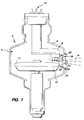
- FIG. 1 is a cross sectional view of the preferred embodiment of the x-ray generating tube of the present invention.
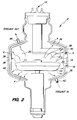
- FIG. 2 is a cross sectional view of a second embodiment of the x-ray generating tube of the present invention.
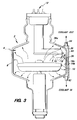
- FIG. 3 is a cross sectional view of a third embodiment of the x-ray generating tube of the present invention.
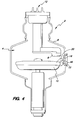
- FIG. 4 is a cross sectional view of a fourth embodiment of the x-ray generating tube of the present invention.
- FIGS. 1-4 illustrate an x-ray generating tube 2 including a vacuum envelope 4 comprising a metal center section 6.
- a stationary cathode 8 and a rotating anode 10 are housed within vacuum envelope 4.
- anode 10 is held at ground potential.
- High voltage means 12 are provided for creating a potential between cathode 8 and anode 10 to cause an electron beam generated by cathode 8 to strike anode 10 with sufficient energy to generate x-rays 14.
- a window 16 permits transmission of x-rays 14 for high power applications.
- Window 16 is preferably constructed of beryllium, but may be any material through which x-rays can be transmitted.
- An enlarged region 22 of metal center section 6 surrounds window 16 such that the window slightly protrudes from the metal center section, outward of vacuum envelope 4.
- Shield 18 is formed integrally with or affixed to the interior surface of enlarged region 22.
- a contoured surface 24 intercepts secondary electrons 20 away from the window area.
- Contoured surface 24 is continuous with the inner surface of center section 6, curving so as to extend toward the interior of vacuum envelope 4 and match the high voltage field lines between cathode 8 and anode 10.
- An interior, transverse face 26 is generally flat and extends from a tip 30 of contoured surface 24 to an indentation 32 for retaining window 16 in place. Interior transverse face 26 is angled slightly from tip 30 outwardly to window 16.
- a generally flat, exterior, transverse face 28 extends from the outer surface of center section 6 to the outer edge of enlarged region 22, approximately aligned with window 16.
- Juxtaposed with exterior transverse face 28 is a coil 34 for circulating a forced coolant around window 16. Heat generated by secondary electrons 20 bombarding shield 18 and heat radiated from target 11 is removed by conduction through the shield and carried away by the forced coolant through coil 34. Because anode 10 is at ground potential along with metal center section 6, it is possible to use water as the selected coolant immediately adjacent to the anode. Thus, the hardware required for cooling is less complicated than would be required for a high voltage anode.
- high voltage means 12 creates a potential between cathode 8 and anode 10 to cause an electron beam to strike the anode with sufficient energy to generate x-rays 14.
- Heat is generated by this electron beam from secondary electrons 20.
- Shield 18 absorbs the secondary electrons, collecting the heat along with heat generated by primary electron beam 14. The heat is conducted by coolant forced through coils 34 to ensure that window 16 remains cool.
- FIGS. 2 and 3 are similar to FIG. 1, differing from FIG. 1 only in the circulation of the forced coolant.
- x-ray generating tube 2 of FIGS. 2 and 3 include metal center section 6, stationary cathode 8, rotating anode 10, window 16 and shield 18.
- a double walled closed space 36 is formed in metal center section 6. Closed space 36 is positioned between an inner wall 38 and an outer wall 40 for circulation of forced coolant. The coolant enters closed space 36 through a coolant inlet 42, circulates around vacuum envelope 4 and exits through a coolant outlet 44.
- Window 16 of FIG. 2 is identical to window 16 of FIG. 1, i.e., slightly protruding from enlarged region 22 outwardly of vacuum envelope 4. Closed space 36 surrounds shield 18 and window 16 for conduction of heat away from the window. Heat radiated from anode 8 is conducted through inner wall 38 and convected away with the liquid coolant circulating between inner wall 38 and outer wall 40.
- a double walled closed space 36 is also formed in metal center section 6.
- metal center section 6 of FIG. 3 is identical to the metal center section of FIG. 1.
- Closed space 36 is localized in the vicinity of window 16. It is positioned between the outer surface 38a of metal center section 6 and an external outer wall 40 coupled to the exterior the metal center section in the vicinity of the window along only one side of vacuum envelope 4.
- An inner window 16a is identical to window 16 of FIG. 1.
- an outer window 16b is formed in external outer wall 40 and spaced from window 16a for transmission of x-rays 14 through both inner window 16a and outer window 16b.
- the coolant enters closed space 36 through a coolant inlet 42, circulates between window 16a and 16b and exits through a coolant outlet 44. Heat generated by primary electrons 14 and heat from secondary electrons 20 is conducted through inner wall 38a and convected away from the circulating cooling fluid.
- x-ray generating tube 2 includes metal center section 6, stationary cathode 8, end-grounded rotating anode 10, high voltage means 12 and window 16.
- FIG. 4 differs from FIG. 1 in the means for deflecting secondary electrons 20 back scattered from anode 10 away from window 16 to avoid secondary electron bombardment of envelope 4.
- FIG. 4 includes, rather than a shield 18 as shown in FIGS. 1-3, a window 16 having a dielectric material such as ceramic or beryllium oxide material on the inner surface 16a of the window. The material selected acts as an insulator for collecting electrons on inner surface 16a of window 16.
- a light coating of semiconductive material 46 is preferably formed on inner surface 16a, electrically insulated from vacuum envelope 4 so as to form a floating potential on inner surface 16a.
- the preferred embodiments describe a rotating anode in a metal center tube; however, it is within the scope of this invention to cool an x-ray generating tube having a stationary anode.
- the embodiment of FIG. 3 may be constructed with or without a shield. In the embodiment without a shield, the closed space, alone, prevents excessive heating of the window.
- the means for preventing excessive heating may be of any form not shown or described herein.
- a magnet may be employed outside of the envelope to deflect secondary electrons from the window.
- a power supply may be attached to any of the described embodiments to produce a charge, thereby enhancing the force for repelling the secondary electrons.
Landscapes
- X-Ray Techniques (AREA)
Abstract
A high power x-ray generating tube (2) for reducing the effects of excessive heating of the window (16) through which the x-rays (16) are transmitted. The x-ray generating tube consists of a metal center section (6) having a stationary cathode (8) and a rotating anode (10). Various embodiments are employed for deflecting secondary electrons back scattered from the anode away from the window to avoid overheating of the window. A grounded anode simplifes the mechanisms required to prevent overheating.
Description
- The present invention relates to reducing the effects of excessive heat buildup on the x-ray transmission window and the tube envelope surfaces of a high power metal envelope x-ray generating tube.
- In x-ray generating tubes, a stream of electrons is emitted from a cathode and accelerated in a high voltage potential difference to strike the target area of an anode surface. Electromagnetic energy is thus produced in the form of x-rays. In many applications, it is desirable to narrowly focus the stream of electrons onto a small area of a rotating anode, known as the "focal spot." In addition, it is often desirable to maximize the energy of the electron stream in order to produce a large amount of high energy x-rays.
- In x-ray tubes, the tube envelope surfaces are heated by several means. Heat is generated in the target from bombardment of the primay electron beam created by the cathode. This heat is radiated to the envelope of the x-ray tube. Heat is also generated in the envelope from secondary electron bombardment from electrons back scattered from the focal spot on the target. In this context, reference to "secondary" electrons includes backscattered electrons. Heating of the envelope is higher in the window area due to the contribution of electrons generated by back scattered secondary electrons. If the temperature in the area of the window rises too high, dielectric oil on the exterior of the x-ray tube will boil or break down. This is highly undesirable since the oil must maintain its electrical dielectric properties in the x-ray tube housing. In certain medical applications such as computed tomography ("CT" or "CAT") scanning, some diagnostic techniques require high energy exposures for relatively long periods of time. The energy input from these exposures can cause overheating of the window area of the x-ray tube envelope causing the dielectric oil to break down due to secondary electron bombardment of the window area and heating from the target. Reducing the energy input to a level that prevents this heating can cause delays that put limits on the time available to gather diagnostic information for the radiologist.
- The buildup of thermal energy in the anode is the first limiting factor in power output, longevity, and efficiency of the x-ray generating tubes. The need for continuous use, high power x-ray tubes has become even stronger with the advent of new types of medical equipment such as CAT scanners and other high power x-ray applications such as digital radiography, and angiography.
- Only a small fraction of the electron energy is converted to x-rays. While most of the electron energy is converted directly to heat energy, some electrons have enough energy to leave the target surface and fly off in random directions. These electrons, still subject to the high voltage field, tend to be reabsorbed back into the target or any other surface which intercepts their course. These "stray" electrons are called "secondary electrons" as opposed to the electrons in the primary beam from the cathode which generate the desired x-rays. Secondary electrons cause undesirable heating when they bombard the envelope surface of the x-ray tube near the focal spot area, which may damage the sealing components, wall material, or cause overheating of the dielectic oil external to the x-ray tube. Radiation produced from the secondary electrons is called "off focal radiation" and is undesirable because it creates a background radiation pattern which does not contribute to the x-ray image. Energy of the secondary electrons, rather than producing x-rays, is released as heat, thereby elevating the anode and envelope tube surface temperatures.
- The use of a rotating anode disperses the energy of the electron stream over a large area, while maintaining a narrow focal spot. Rotating anode x-ray generating tubes are now common, and details of their construction and operation are readily available. However, even with a rotating anode design, the buildup of thermal energy in the anode structure remains a problem. Since the anode structure operates in a vacuum, heat cannot be carried away from the anode surface by convection. Some heat can be conducted to the exterior of the tube through the bearing structure of the rotating anode. However, heat buildup in the bearing structure is a major cause of tube failure. Generally, it is desirable to thermally isolate the bearing, thereby minimizing the heat loss by conduction.
- High power x-ray generating tubes typically include a glass center portion immersed in dielectric oil. However, it is possible to achieve higher power levels with tubes having a metal center section. The propensity to overheat in the window area of x-ray tubes is seen mainly in high power applications in metal center x-ray tubes. By reducing the power, heat buildup can be reduced. However, this resolution is not satisfactory for applications requiring high power. Alternatively, attempts have been made to reduce the effects of heat buildup.
- One approach to increasing the thermal capacity of rotating anode x-ray tubes has been to increase the radius volume of the anode disk, thereby increasing the mass of material capable of storing the thermal energy imparted by the electron beam. However, such designs do not increase the capacity of the anode to dispose of thermal energy. Under continuous use, such designs again result in heat buildup. Moreover, this approach has the further disadvantage of amplifying the mechanical motions of the anode as it rotates and increasing the difficulty of maintaining the mechanical tolerances of the anode structure. The overall moment of inertia of the anode is increased, thereby necessitating greater input of rotational energy.
- Secondary electron heating and off focus radiation has been addressed in stationary anode x-ray tubes. Elaborate means have been employed to reduce off focus radiation and anode heating. "Hooded" anodes with beryllium windows have been used to collect secondary electrons. These anodes are liquid cooled by various methods, usually from behind the stationary target and inside the hood surrounding the target. Cooling of these systems has been limited to cooling of the anode structure alone.
- U.S. Patent No. 4,819,260 and European Patent No. B1 0 059 238 address oll focal radiation. U.S. Patent No. 4,819,260 is directed to a magnetically controlled electron beam which prevents migration of the focal spot of an electron stream on a rotating anode. European Patent No. B1 0 059 238 discloses a metal screen which is inserted between the cathode and the anode and a voltage is applied to the screen. Neither of these systems addresses heat produced by secondary electron bombardment to cool the vacuum envelope.
- U.S. Statutory Invention Registration No. H312 addresses heat dissipation of the anode structure. Fins are provided adjacent to the anode structure for enhancing heat transfer from the anode structure to the region outside the vacuum envelope. As in the previously discussed references, this publication does not address heat dissipation of the vacuum envelope due to secondary electron bombardment.
- U.S. Patent No. 4,841,557 discloses a rotating anode in which the housing is cooled by circulating, within the housing body, the outer immersion fluid in which the housing is retained. Interior conduits and connections require that a complicated structure be included for circulation of the fluid.
- None of the prior art addresses dissipating heat generated by secondary electron bombardment to cool the tube envelope. Traditionally, the anode is maintained at a high positive voltage while the cathode is maintained at an equally high negative voltage to achieve a potential of approximately 150,000 volts. Although higher power levels are precluded by this traditional split because of secondary electron bombardment of the tube envelope, it alleviates intensified heating of the x-ray tube envelope and window area. With increased demand for higher power applications, cooling of the vacuum tube envelope must be expressly addressed.
- Accordingly, it is a primary object of the invention to provide means for dissipating heat generated by secondary electron bombardment from the rotating anode structure of an x-ray generating tube having a metal center section.
- Another object of this invention is to provide an anode structure maintained at ground potential.
- It is a further object of the invention to provide means to reduce overheating of the x-ray tube envelope by controlling the secondary electron heating and heat transfer from the target area.
- The present invention relates to a high power metal center x-ray generating tube for reducing the effects of excessive heating of the x-ray transmission window by secondary electron bombardment.
- The present invention includes an x-ray generating tube consisting of a vacuum envelope having a metal center section, a stationary cathode and a rotating anode. A high potential is created between the rotating anode and the cathode to cause an electron beam to strike the anode with sufficient energy to generate an x-ray beam through a window formed in the tube envelope. The present invention seeks to dissipate heat which can be generated in two ways. First, heat is generated in the target from bombardment of the primary electron x-ray beam created by the cathode. This heat is radiated to the envelope of the x-ray tube. Second, heat is generated in the envelope from seconday electron bombardment from electrons back scattered from the target.
- The rotating anode is preferably held at ground potential along with the metal center section, while the cathode is at high voltage so as to maintain a potential between the cathode and anode. It is thus possible to provide a more intimate design between the cooling means and anode, using a coolant, such as water, which need not provide a dielectric standoff between the anode and cooling means. With the anode at ground, the hardware mechanism for cooling is less complicated. Alternatively, the anode can be at high positive voltage and the cathode at high negative voltage, resulting in a similar potential difference.
- In the preferred embodiment, a shield intercepts back scattered secondary electrons, preventing them from striking the window, thereby avoiding secondary electron bombardment of the window. The shield is disposed adjacent to the window and includes a contoured surface to match the high voltage field lines between the cathode and anode. A coolant is circulated around the outer portion of the window to dissipate heat. As discussed above, because the metal center section is at ground potential, it is possible to circulate water as the selected coolant.
- In an alternate embodiment, heat generation by the secondary electrons back scattered from the anode is mitigated by way of an insulating means. The insulating means provides a build up of negative charge on the inner surface of the window to decelerate and repel the back scattered electrons, reducing the amount of electron energy bombarding the window and, thereby, reducing excessive heating of the window. Electrons are collected on the inner surface of the window for build up of a negative charge to repel electrons from the window surface. A coating of conductive material may also be formed on the window surface. In this case, the window is electrically insulated from the envelope so as to form a floating potential on the surface of the window.
- In another embodiment of the invention, the effects of excessive heating are reduced by a double wall formed in the metal center section in the vicinity of the window. A closed space is created between an inner and outer wall for circulation of a coolant to conduct heat through the inner wall and away from the window. The window also includes an inner and outer window in the respective inner and outer walls. Alternatively, a closed space can be formed such that coolant is circulated around the entire portion of the metal center section.
Examples of the invention will now be described with reference to the accompanying drawings in which: - FIG. 1 is a cross sectional view of the preferred embodiment of the x-ray generating tube of the present invention.
- FIG. 2 is a cross sectional view of a second embodiment of the x-ray generating tube of the present invention.
- FIG. 3 is a cross sectional view of a third embodiment of the x-ray generating tube of the present invention.
- FIG. 4 is a cross sectional view of a fourth embodiment of the x-ray generating tube of the present invention.
- FIGS. 1-4 illustrate an
x-ray generating tube 2 including avacuum envelope 4 comprising ametal center section 6. Astationary cathode 8 and a rotatinganode 10 are housed withinvacuum envelope 4. In the preferred embodiment,anode 10 is held at ground potential. High voltage means 12 are provided for creating a potential betweencathode 8 andanode 10 to cause an electron beam generated bycathode 8 to strikeanode 10 with sufficient energy to generatex-rays 14. Awindow 16 permits transmission ofx-rays 14 for high power applications.Window 16 is preferably constructed of beryllium, but may be any material through which x-rays can be transmitted. - Referring now to FIG. 1, a
shield 18, preferably constructed of copper, interceptssecondary electrons 20 back scattered fromanode 10 away fromwindow 16 to avoid secondary electron bombardment ofenvelope 4 and, thereby, to prevent overheating of the window.Secondary electrons 20, still subject to the high voltage field, tend to be reabsorbed back intotarget area 11 ofanode 10 or any other surface which intercepts their course. - An
enlarged region 22 ofmetal center section 6 surroundswindow 16 such that the window slightly protrudes from the metal center section, outward ofvacuum envelope 4.Shield 18 is formed integrally with or affixed to the interior surface ofenlarged region 22. A contouredsurface 24 interceptssecondary electrons 20 away from the window area. Contouredsurface 24 is continuous with the inner surface ofcenter section 6, curving so as to extend toward the interior ofvacuum envelope 4 and match the high voltage field lines betweencathode 8 andanode 10. An interior,transverse face 26 is generally flat and extends from atip 30 of contouredsurface 24 to an indentation 32 for retainingwindow 16 in place. Interiortransverse face 26 is angled slightly fromtip 30 outwardly towindow 16. A generally flat, exterior,transverse face 28 extends from the outer surface ofcenter section 6 to the outer edge ofenlarged region 22, approximately aligned withwindow 16. - Juxtaposed with exterior
transverse face 28 is acoil 34 for circulating a forced coolant aroundwindow 16. Heat generated bysecondary electrons 20 bombardingshield 18 and heat radiated fromtarget 11 is removed by conduction through the shield and carried away by the forced coolant throughcoil 34. Becauseanode 10 is at ground potential along withmetal center section 6, it is possible to use water as the selected coolant immediately adjacent to the anode. Thus, the hardware required for cooling is less complicated than would be required for a high voltage anode. - In operation, high voltage means 12 creates a potential between
cathode 8 andanode 10 to cause an electron beam to strike the anode with sufficient energy to generatex-rays 14. Heat is generated by this electron beam fromsecondary electrons 20.Shield 18 absorbs the secondary electrons, collecting the heat along with heat generated byprimary electron beam 14. The heat is conducted by coolant forced throughcoils 34 to ensure thatwindow 16 remains cool. - The embodiments shown in FIGS. 2 and 3 are similar to FIG. 1, differing from FIG. 1 only in the circulation of the forced coolant. As discussed with reference to FIG. 1,
x-ray generating tube 2 of FIGS. 2 and 3 includemetal center section 6,stationary cathode 8, rotatinganode 10,window 16 andshield 18. - Turning first to FIG. 2, a double walled
closed space 36 is formed inmetal center section 6.Closed space 36 is positioned between aninner wall 38 and anouter wall 40 for circulation of forced coolant. The coolant enters closedspace 36 through acoolant inlet 42, circulates aroundvacuum envelope 4 and exits through acoolant outlet 44.Window 16 of FIG. 2 is identical towindow 16 of FIG. 1, i.e., slightly protruding fromenlarged region 22 outwardly ofvacuum envelope 4.Closed space 36 surroundsshield 18 andwindow 16 for conduction of heat away from the window. Heat radiated fromanode 8 is conducted throughinner wall 38 and convected away with the liquid coolant circulating betweeninner wall 38 andouter wall 40. - Turning now to FIG. 3, a double walled
closed space 36 is also formed inmetal center section 6. Unlike the embodiment of FIG. 2 in which the entire metal center section is double walled,metal center section 6 of FIG. 3 is identical to the metal center section of FIG. 1.Closed space 36 is localized in the vicinity ofwindow 16. It is positioned between theouter surface 38a ofmetal center section 6 and an externalouter wall 40 coupled to the exterior the metal center section in the vicinity of the window along only one side ofvacuum envelope 4. Aninner window 16a is identical towindow 16 of FIG. 1. Additionally, anouter window 16b is formed in externalouter wall 40 and spaced fromwindow 16a for transmission ofx-rays 14 through bothinner window 16a andouter window 16b. In operation of FIG. 3, the coolant enters closedspace 36 through acoolant inlet 42, circulates betweenwindow coolant outlet 44. Heat generated byprimary electrons 14 and heat fromsecondary electrons 20 is conducted throughinner wall 38a and convected away from the circulating cooling fluid. - Referring to FIG. 4,
x-ray generating tube 2 includesmetal center section 6,stationary cathode 8, end-groundedrotating anode 10, high voltage means 12 andwindow 16. FIG. 4 differs from FIG. 1 in the means for deflectingsecondary electrons 20 back scattered fromanode 10 away fromwindow 16 to avoid secondary electron bombardment ofenvelope 4. FIG. 4 includes, rather than ashield 18 as shown in FIGS. 1-3, awindow 16 having a dielectric material such as ceramic or beryllium oxide material on theinner surface 16a of the window. The material selected acts as an insulator for collecting electrons oninner surface 16a ofwindow 16. These electrons have no conductive path and, therefore, build up anegative charge 15 oninner surface 16a to cause a certain percentage ofsecondary electrons 20 to decelerate or be repelled before stridingwindow surface 16a. Thus, the effect of providing an insulating material oninner surface 16a serves to reduce the amount of electron energy imparted to the window surface, thereby, reducing excessive heating ofwindow 16. A light coating ofsemiconductive material 46 is preferably formed oninner surface 16a, electrically insulated fromvacuum envelope 4 so as to form a floating potential oninner surface 16a. However, it is within the scope of the present invention to constructinner surface 16a of an insulating material, without providing a semiconductive layer. - Variations and modifications can be made to the present invention without departing from the scope of the present invention. For example, the preferred embodiments describe a rotating anode in a metal center tube; however, it is within the scope of this invention to cool an x-ray generating tube having a stationary anode. The embodiment of FIG. 3 may be constructed with or without a shield. In the embodiment without a shield, the closed space, alone, prevents excessive heating of the window. The means for preventing excessive heating may be of any form not shown or described herein. For example, a magnet may be employed outside of the envelope to deflect secondary electrons from the window. A power supply may be attached to any of the described embodiments to produce a charge, thereby enhancing the force for repelling the secondary electrons.
Claims (23)
- A high power rotating anode x-ray generating tube comprising:
a vacuum envelope having a metal center section;
an ante structure disposed within said center section for rotation about an axis;
cathode means within said center section for generating a beam of electrons;
high voltage means for maintaining a potential between said anode structure and said cathode means to cause said electron beam to strike said cathode means with sufficient energy to generate x-rays;
a window formed in said center section for transmission of said x-rays outside said envelope; and
means for preventing the excessive heating of said window. - The x-ray generating tube of claim 1 wherein said means for preventing comprises means for deflecting electrons from striking said window.
- The x-ray generating tube of claim 2 wherein said means for deflecting comprises shield means disposed adjacent said window.
- The x-ray generating tube of claim 3 wherein said shield is configured to match high voltage field lines between said cathode means and said anode structure.
- The x-ray generating tube of claim 1 wherein said anode structure is maintained at ground and wherein said cathode means is maintained at high voltage.
- The x-ray generating tube of claim 5 further comprising means for circulating coolant around said preventing means.
- The x-ray generating tube of claim 1 wherein said means for preventing comprises heat transfer means for transferring heat from said window and said envelope.
- The x-ray generating tube of claim 7 wherein said heat transfer means are constructed of copper.
- The x-ray generating tube of claim 1 wherein said means for preventing comprises means for collecting electrons on an inner surface of said window for build up of a negative charge thereon to thereby repel electrons from said window surface.
- The x-ray generating tube of claim 9 wherein said window is electrically insulated from said envelope so as to form a floating potential on the surface of said window.
- The x-ray generating tube of claim 9 wherein said means for collecting comprises insulating said window from said metal center section.
- The x-ray generating tube of claim 9 further comprising a coating of conductive material on said window surface.
- The x-ray generating tube of claim 1 wherein said means for preventing comprises an inner wall and an outer wall having a closed space therebetween for circulating coolant between said walls such that heat generated by transmission of said electrons is conducted through said inner wall and convected away from said window.
- The x-ray generating tube of claim 13 wherein said inner wall and said outer wall encircle said entire center section.
- The x-ray generating tube of claim 13 wherein said inner wall and said outer wall are localized in the vicinity of said window and wherein said window comprises an inner window and an outer window formed in said inner wall and said outer wall, respectively.
- An x-ray generating tube comprising:
a vacuum envelope having a metal center section;
rotating anode means disposed within said center section maintained at ground potential;
cathode means maintained at high voltage and disposed within said center section for generating a beam of electrons with sufficient energy to generate x-rays;
a window for transmission of said x-rays outside said envelope, said window being constructed of beryllium; and
shield means for deflecting secondary electrons back scattered from said anode means away from said window to avoid secondary electron bombardment of said envelope and, thereby, to prevent overheating of said window, said shield means mounted to the interior of said metal center section and having a contoured surface to match high voltage field lines between said cathode means and said anode means. - The x-ray generating tube of claim 16 further comprising means for circulating fluid around said window and thereby cooling said window.
- A high power x-ray generating tube comprising:
a vacuum envelope having a metal center section;
anode means disposed within said center section for rotation about an axis;
cathode means maintained at high voltage and disposed within said center section for generating a beam of electrons with sufficient energy to generate x-rays;
a window formed in said center section for transmission of said x-rays outside said envelope, said window including insulating means for providing a build up of negative charge on an inner surface of said window to repel secondary electrons back scattered from said anode to thereby reduce the amount of electron energy bombarding said window to therefor reduce heating of said window. - The x-ray generating tube of claim 18 further comprising a coating of conductive material on said window surface.
- A high power x-ray generating tube comprising:
a vacuum envelope having a metal center section;
an anode structure disposed within said center section for rotation about an axis;
cathode means within said center section for generating a beam of electrons with sufficient energy to generate x-rays;
a portion of said center section including an inner wall and an outer wall;
a window formed in said portion of said center section for transmission of said x-rays outside said envelope;
a closed space for circulating liquid coolant within said closed space such that heat generated by bombardment of said windows by secondary electrons back scattered from said anode is conducted through said inner wall and carried from said window by convection to thereby cool said tube envelope. - The x-ray generating tube of claim 20 wherein said portion of said center section comprises the entire center section.
- The x-ray generating tube of claim 20 further comprising an inner window in said inner wall and an outer window in said outer wall generally parallel to said inner window and wherein said portion of said center section is localized in the vicinity of said windows such that said closed space is formed between said inner window and said outer window.
- A high power generating tube comprising:
a vacuum envelope having a metal center section;
rotating anode means disposed within said center section for rotation about an axis;
stationary cathode means disposed within said center section and maintained at high voltage for generating a beam of electrons with sufficient energy to generate x-rays;
a window formed in said center section for transmission of said x-rays outside said envelope; and
means mounted to said center section for dissipating electrons back scattered from said ante away from said means toward the interior of said envelope.
Priority Applications (1)
| Application Number | Priority Date | Filing Date | Title |
|---|---|---|---|
| EP99123769A EP0991106A3 (en) | 1990-11-21 | 1991-11-21 | High power X-Ray tube |
Applications Claiming Priority (2)
| Application Number | Priority Date | Filing Date | Title |
|---|---|---|---|
| US61646490A | 1990-11-21 | 1990-11-21 | |
| US616464 | 1990-11-21 |
Related Child Applications (1)
| Application Number | Title | Priority Date | Filing Date |
|---|---|---|---|
| EP99123769A Division EP0991106A3 (en) | 1990-11-21 | 1991-11-21 | High power X-Ray tube |
Publications (2)
| Publication Number | Publication Date |
|---|---|
| EP0491471A2 true EP0491471A2 (en) | 1992-06-24 |
| EP0491471A3 EP0491471A3 (en) | 1992-09-30 |
Family
ID=24469581
Family Applications (2)
| Application Number | Title | Priority Date | Filing Date |
|---|---|---|---|
| EP99123769A Withdrawn EP0991106A3 (en) | 1990-11-21 | 1991-11-21 | High power X-Ray tube |
| EP19910310751 Withdrawn EP0491471A3 (en) | 1990-11-21 | 1991-11-21 | High power x-ray tube |
Family Applications Before (1)
| Application Number | Title | Priority Date | Filing Date |
|---|---|---|---|
| EP99123769A Withdrawn EP0991106A3 (en) | 1990-11-21 | 1991-11-21 | High power X-Ray tube |
Country Status (2)
| Country | Link |
|---|---|
| EP (2) | EP0991106A3 (en) |
| JP (1) | JPH04315752A (en) |
Cited By (7)
| Publication number | Priority date | Publication date | Assignee | Title |
|---|---|---|---|---|
| EP0924742A2 (en) * | 1997-12-19 | 1999-06-23 | Picker International, Inc. | Means for preventing excessive heating of an X-ray tube window |
| EP1475819A2 (en) | 1997-08-29 | 2004-11-10 | Varian Medical Systems Technologies, Inc. | X-ray generating apparatus with integral housing |
| WO2004107384A2 (en) * | 2003-05-30 | 2004-12-09 | Koninklijke Philips Electronics N.V. | Enhanced electron backscattering in x-ray tubes |
| WO2006003533A1 (en) * | 2004-06-30 | 2006-01-12 | Koninklijke Philips Electronics, N.V. | X-ray tube cooling apparatus |
| DE102008038569A1 (en) * | 2008-08-20 | 2010-02-25 | Siemens Aktiengesellschaft | X-ray tube |
| US20140177796A1 (en) * | 2011-06-07 | 2014-06-26 | Canon Kabushiki Kaisha | X-ray tube |
| US20150043718A1 (en) * | 2013-08-08 | 2015-02-12 | Ronald Dittrich | Single-Pole X-Ray Emitter |
Families Citing this family (12)
| Publication number | Priority date | Publication date | Assignee | Title |
|---|---|---|---|---|
| US6215852B1 (en) * | 1998-12-10 | 2001-04-10 | General Electric Company | Thermal energy storage and transfer assembly |
| US6714626B1 (en) * | 2002-10-11 | 2004-03-30 | Ge Medical Systems Global Technology Company, Llc | Jet cooled x-ray tube window |
| US7016472B2 (en) * | 2002-10-11 | 2006-03-21 | General Electric Company | X-ray tube window cooling apparatus |
| JP4644508B2 (en) * | 2005-03-30 | 2011-03-02 | 東芝電子管デバイス株式会社 | X-ray tube |
| JP4828895B2 (en) * | 2005-08-29 | 2011-11-30 | 株式会社東芝 | Voltage application method for X-ray tube apparatus and X-ray tube apparatus |
| DE102005049455B4 (en) * | 2005-10-15 | 2007-11-22 | Ziehm Imaging Gmbh | Heat exchanger for a single-boiler generator of an X-ray diagnostic device with a rotary anode tube with glass housing |
| US7616736B2 (en) * | 2007-09-28 | 2009-11-10 | Varian Medical Systems, Inc. | Liquid cooled window assembly in an x-ray tube |
| JP5225881B2 (en) * | 2008-02-08 | 2013-07-03 | バリアン・メディカル・システムズ・インコーポレイテッド | X-ray tube and X-ray tube cooling system |
| JP5580288B2 (en) * | 2008-04-17 | 2014-08-27 | コーニンクレッカ フィリップス エヌ ヴェ | X-ray tube with passive ion collector |
| US8130910B2 (en) * | 2009-08-14 | 2012-03-06 | Varian Medical Systems, Inc. | Liquid-cooled aperture body in an x-ray tube |
| JP2010104819A (en) * | 2010-02-01 | 2010-05-13 | Toshiba Corp | X-ray computer tomographic apparatus and x-ray tube device |
| CN106504967B (en) * | 2016-12-14 | 2018-01-30 | 云南电网有限责任公司电力科学研究院 | Negative and positive two have the X-ray tube of spinfunction |
Citations (4)
| Publication number | Priority date | Publication date | Assignee | Title |
|---|---|---|---|---|
| US3124710A (en) * | 1960-03-17 | 1964-03-10 | X-ray tubes | |
| US3334256A (en) * | 1964-03-20 | 1967-08-01 | Dunlee Corp | Sealed window for x-ray generator with shield for seal |
| EP0009946A1 (en) * | 1978-10-02 | 1980-04-16 | Pfizer Inc. | X-ray tube |
| JPS60101848A (en) * | 1983-11-09 | 1985-06-05 | Hitachi Ltd | X-ray tube |
Family Cites Families (5)
| Publication number | Priority date | Publication date | Assignee | Title |
|---|---|---|---|---|
| BE355009A (en) * | 1927-10-18 | |||
| BE501636A (en) * | 1950-03-04 | |||
| DE2833093A1 (en) * | 1978-07-28 | 1980-02-07 | Licentia Gmbh | X=ray tube with slanting anode and copper casing with window - which comprises two beryllium, aluminium titanium or epoxy! discs doubling as cooling duct |
| JPS5818900A (en) * | 1981-07-27 | 1983-02-03 | Hitachi Ltd | X-ray tube device |
| US4731804A (en) * | 1984-12-31 | 1988-03-15 | North American Philips Corporation | Window configuration of an X-ray tube |
-
1991
- 1991-11-21 EP EP99123769A patent/EP0991106A3/en not_active Withdrawn
- 1991-11-21 JP JP3331516A patent/JPH04315752A/en active Pending
- 1991-11-21 EP EP19910310751 patent/EP0491471A3/en not_active Withdrawn
Patent Citations (4)
| Publication number | Priority date | Publication date | Assignee | Title |
|---|---|---|---|---|
| US3124710A (en) * | 1960-03-17 | 1964-03-10 | X-ray tubes | |
| US3334256A (en) * | 1964-03-20 | 1967-08-01 | Dunlee Corp | Sealed window for x-ray generator with shield for seal |
| EP0009946A1 (en) * | 1978-10-02 | 1980-04-16 | Pfizer Inc. | X-ray tube |
| JPS60101848A (en) * | 1983-11-09 | 1985-06-05 | Hitachi Ltd | X-ray tube |
Non-Patent Citations (1)
| Title |
|---|
| PATENT ABSTRACTS OF JAPAN, vol. 9, no. 251 (E-348)[1974], 8th October 1985; & JP-A-60 101 848 (HITACHI) 05-06-1985 * |
Cited By (12)
| Publication number | Priority date | Publication date | Assignee | Title |
|---|---|---|---|---|
| EP1475819A2 (en) | 1997-08-29 | 2004-11-10 | Varian Medical Systems Technologies, Inc. | X-ray generating apparatus with integral housing |
| EP1475819B1 (en) * | 1997-08-29 | 2013-03-06 | Varian Medical Systems, Inc. | X-ray generating apparatus with integral housing |
| EP0924742A2 (en) * | 1997-12-19 | 1999-06-23 | Picker International, Inc. | Means for preventing excessive heating of an X-ray tube window |
| EP0924742A3 (en) * | 1997-12-19 | 2000-01-05 | Picker International, Inc. | Means for preventing excessive heating of an X-ray tube window |
| WO2004107384A2 (en) * | 2003-05-30 | 2004-12-09 | Koninklijke Philips Electronics N.V. | Enhanced electron backscattering in x-ray tubes |
| WO2004107384A3 (en) * | 2003-05-30 | 2005-07-07 | Koninkl Philips Electronics Nv | Enhanced electron backscattering in x-ray tubes |
| US7260181B2 (en) | 2003-05-30 | 2007-08-21 | Koninklijke Philips Electronics, N.V. | Enhanced electron backscattering in x-ray tubes |
| WO2006003533A1 (en) * | 2004-06-30 | 2006-01-12 | Koninklijke Philips Electronics, N.V. | X-ray tube cooling apparatus |
| DE102008038569A1 (en) * | 2008-08-20 | 2010-02-25 | Siemens Aktiengesellschaft | X-ray tube |
| US20140177796A1 (en) * | 2011-06-07 | 2014-06-26 | Canon Kabushiki Kaisha | X-ray tube |
| US20150043718A1 (en) * | 2013-08-08 | 2015-02-12 | Ronald Dittrich | Single-Pole X-Ray Emitter |
| US9257255B2 (en) * | 2013-08-08 | 2016-02-09 | Siemens Aktiengesellschaft | Single-pole x-ray emitter |
Also Published As
| Publication number | Publication date |
|---|---|
| EP0991106A2 (en) | 2000-04-05 |
| EP0991106A3 (en) | 2000-05-03 |
| JPH04315752A (en) | 1992-11-06 |
| EP0491471A3 (en) | 1992-09-30 |
Similar Documents
| Publication | Publication Date | Title |
|---|---|---|
| EP0491471A2 (en) | High power x-ray tube | |
| JP4142748B2 (en) | High performance X-ray generator with cooling system | |
| US9576766B2 (en) | Graphite backscattered electron shield for use in an X-ray tube | |
| US6430260B1 (en) | X-ray tube anode cooling device and systems incorporating same | |
| US6301332B1 (en) | Thermal filter for an x-ray tube window | |
| US6134299A (en) | X-ray generating apparatus | |
| US6005918A (en) | X-ray tube window heat shield | |
| US6361208B1 (en) | Mammography x-ray tube having an integral housing assembly | |
| US8331535B2 (en) | Graphite backscattered electron shield for use in an X-ray tube | |
| US5105456A (en) | High duty-cycle x-ray tube | |
| US7978824B2 (en) | X-ray tube having transmission anode | |
| US6707882B2 (en) | X-ray tube heat barrier | |
| US6477231B2 (en) | Thermal energy transfer device and x-ray tubes and x-ray systems incorporating same | |
| EP0473852A1 (en) | Rotating X-ray tube with external bearings | |
| IL122998A (en) | X-ray generating apparatus with a heat transfer device | |
| US6041100A (en) | Cooling device for x-ray tube bearing assembly | |
| US6594341B1 (en) | Liquid-free x-ray insert window | |
| US6125169A (en) | Target integral heat shield for x-ray tubes | |
| EP0009946A1 (en) | X-ray tube | |
| US5535255A (en) | System for the cooling of an anode for an X-ray tube in a radiogenic unit without heat exchanger | |
| CN100555549C (en) | Enhanced electron backscattering in the X-ray tube | |
| USH312H (en) | Rotating anode x-ray tube | |
| JP2006302648A (en) | Rotary positive electrode x-ray tube device | |
| JP3030069B2 (en) | X-ray tube |
Legal Events
| Date | Code | Title | Description |
|---|---|---|---|
| PUAI | Public reference made under article 153(3) epc to a published international application that has entered the european phase |
Free format text: ORIGINAL CODE: 0009012 |
|
| AK | Designated contracting states |
Kind code of ref document: A2 Designated state(s): DE FR GB |
|
| PUAL | Search report despatched |
Free format text: ORIGINAL CODE: 0009013 |
|
| AK | Designated contracting states |
Kind code of ref document: A3 Designated state(s): DE FR GB |
|
| 17P | Request for examination filed |
Effective date: 19930222 |
|
| 17Q | First examination report despatched |
Effective date: 19940808 |
|
| STAA | Information on the status of an ep patent application or granted ep patent |
Free format text: STATUS: THE APPLICATION HAS BEEN WITHDRAWN |
|
| 18W | Application withdrawn |
Withdrawal date: 19991130 |