EP0491264A1 - Magnetic disc - Google Patents
Magnetic disc Download PDFInfo
- Publication number
- EP0491264A1 EP0491264A1 EP91121139A EP91121139A EP0491264A1 EP 0491264 A1 EP0491264 A1 EP 0491264A1 EP 91121139 A EP91121139 A EP 91121139A EP 91121139 A EP91121139 A EP 91121139A EP 0491264 A1 EP0491264 A1 EP 0491264A1
- Authority
- EP
- European Patent Office
- Prior art keywords
- magnetic disc
- servo
- sector
- magnetic
- data
- Prior art date
- Legal status (The legal status is an assumption and is not a legal conclusion. Google has not performed a legal analysis and makes no representation as to the accuracy of the status listed.)
- Granted
Links
Images


Classifications
-
- G—PHYSICS
- G11—INFORMATION STORAGE
- G11B—INFORMATION STORAGE BASED ON RELATIVE MOVEMENT BETWEEN RECORD CARRIER AND TRANSDUCER
- G11B20/00—Signal processing not specific to the method of recording or reproducing; Circuits therefor
- G11B20/10—Digital recording or reproducing
- G11B20/12—Formatting, e.g. arrangement of data block or words on the record carriers
-
- G—PHYSICS
- G11—INFORMATION STORAGE
- G11B—INFORMATION STORAGE BASED ON RELATIVE MOVEMENT BETWEEN RECORD CARRIER AND TRANSDUCER
- G11B5/00—Recording by magnetisation or demagnetisation of a record carrier; Reproducing by magnetic means; Record carriers therefor
- G11B5/012—Recording on, or reproducing or erasing from, magnetic disks
-
- G—PHYSICS
- G11—INFORMATION STORAGE
- G11B—INFORMATION STORAGE BASED ON RELATIVE MOVEMENT BETWEEN RECORD CARRIER AND TRANSDUCER
- G11B20/00—Signal processing not specific to the method of recording or reproducing; Circuits therefor
- G11B20/10—Digital recording or reproducing
- G11B20/12—Formatting, e.g. arrangement of data block or words on the record carriers
- G11B20/1217—Formatting, e.g. arrangement of data block or words on the record carriers on discs
- G11B20/1258—Formatting, e.g. arrangement of data block or words on the record carriers on discs where blocks are arranged within multiple radial zones, e.g. Zone Bit Recording or Constant Density Recording discs, MCAV discs, MCLV discs
-
- G—PHYSICS
- G11—INFORMATION STORAGE
- G11B—INFORMATION STORAGE BASED ON RELATIVE MOVEMENT BETWEEN RECORD CARRIER AND TRANSDUCER
- G11B5/00—Recording by magnetisation or demagnetisation of a record carrier; Reproducing by magnetic means; Record carriers therefor
- G11B5/48—Disposition or mounting of heads or head supports relative to record carriers ; arrangements of heads, e.g. for scanning the record carrier to increase the relative speed
- G11B5/54—Disposition or mounting of heads or head supports relative to record carriers ; arrangements of heads, e.g. for scanning the record carrier to increase the relative speed with provision for moving the head into or out of its operative position or across tracks
- G11B5/55—Track change, selection or acquisition by displacement of the head
- G11B5/5521—Track change, selection or acquisition by displacement of the head across disk tracks
- G11B5/5526—Control therefor; circuits, track configurations or relative disposition of servo-information transducers and servo-information tracks for control thereof
- G11B5/553—Details
- G11B5/5534—Initialisation, calibration, e.g. cylinder "set-up"
- G11B5/5543—Initialisation, calibration, e.g. cylinder "set-up" servo-format therefor
-
- G—PHYSICS
- G11—INFORMATION STORAGE
- G11B—INFORMATION STORAGE BASED ON RELATIVE MOVEMENT BETWEEN RECORD CARRIER AND TRANSDUCER
- G11B20/00—Signal processing not specific to the method of recording or reproducing; Circuits therefor
- G11B20/10—Digital recording or reproducing
- G11B20/12—Formatting, e.g. arrangement of data block or words on the record carriers
- G11B2020/1264—Formatting, e.g. arrangement of data block or words on the record carriers wherein the formatting concerns a specific kind of data
- G11B2020/1265—Control data, system data or management information, i.e. data used to access or process user data
- G11B2020/1281—Servo information
- G11B2020/1282—Servo information in embedded servo fields
-
- G—PHYSICS
- G11—INFORMATION STORAGE
- G11B—INFORMATION STORAGE BASED ON RELATIVE MOVEMENT BETWEEN RECORD CARRIER AND TRANSDUCER
- G11B2220/00—Record carriers by type
- G11B2220/20—Disc-shaped record carriers
- G11B2220/25—Disc-shaped record carriers characterised in that the disc is based on a specific recording technology
- G11B2220/2508—Magnetic discs
Definitions
- the present invention generally relates to a magnetic disc and a magnetic disc apparatus for recording, reproducing data, and more particularly, a magnetic disc for obtaining large recording capacity with a special format, and a mass magnetic disc apparatus for recording, reproducing data on it.
- a magnetic disc apparatus As a magnetic disc apparatus is capable of storing a large quantity of data, and accessing the data with high speeds with a random access system, it is widely spread as a data storage system. Unlike the tape apparatus, the data are recorded on the tracks of many concentric circles on the surface of the disc plate. The tracks on the internal peripheral side are shorter in length than the tracks on the external peripheral side, thus resulting in higher recording density as the tracks go towards the internal peripheries. On the other hand, as the external peripheral side is lower in the recording density, the possibility of further increasing the record capacity remains because of increased record density on the external peripheral side in terms of the magnetic recording operation.
- a hard disc apparatus including a positioning apparatus for taking in and out in the radial direction of the disc a disc assembly with many hard discs being stacked in the axial direction with the use of the hard disc having a magnetic material filmed on a disc shaped aluminum or a glass basic board, and a head carriage constructed with many magnetic heads being assembled respectively on each face of the disc are well known.
- the specific one face of the stacked disc is not used for data writing, but is used for recording servo-pattern signals necessary for positioning the head carriage.
- the head is positioned in a selected track by the reproducing operation of the servo-pattern signal. This is called a servo-face servo-system or a dedicated servo system.
- the data signal recording face and the servo-pattern signal recording face respectively exist independently in the hard disc apparatus of such a system, it is easy to position the head in an optional track, no matter how the format of each tack on the data signal recording face is constructed.
- tracks on many concentric circles on the data signal recording face are divided into some groups (zones) so as to increase the number of the data sectors as the tracks goes to the zone of the further external peripheral portion.
- the recording density can be increased comparatively uniformly and within an allowable range.
- a problem if any is that as the revolution of the disc is constant, the peripheral speed is faster as the periphery becomes further external, the data transfer speed in the zone of the external periphery becomes higher. In recent years, as the processing speed of the electronic circuit has been improved considerably, it is adopted.
- a data face servo system which inserts (inserts a servo-sector of extremely narrow width) the servo-pattern signals between the data sector and the data sector, instead of a servo-face servo-system.
- This is called an embedded servo system.
- the system is a hybrid system of debunchingly dispersing onto the data signal reproducing face the servo-pattern signals necessary for positioning the head.
- the flexible magnetic disc apparatus using a magnetic disc having a magnetic membrane filmed on such a flexible medium as in polyethylene terephthalate or the like is a system most spread among magnetic disc apparatuses of an exchange type. Even in this case, a problem similar to a hard disc apparatus less in disc number is considered. Recently, the flexible magnetic disc is also made higher in capacity, especially the track density becomes made higher, the track pitch becomes made finer, so that a highly precise servo-positioning operation is made necessary. Therefore, even in the such mass flexible magnetic disc, the data face servo-system is adopted. This is disclosed in detail in, for example, Japanese Laid-Open Patent Application No. 63-173282.
- the servo-sector As the servo-sector is grasped between data sectors in the above described data face servo-system, it is difficult to freely effect the data format. It is simple and convenient in the servo control to detect debunching servo-pattern signals for a constant sampling time (debunching time) no matter which position a head is located. Namely, the servo-pattern signal (servo-sector) of each track may be disposed at equal angle from the internal periphery of the disc to the external periphery. In other words, it is desirable to have the angle of the data sector formatted at equal angle across the whole periphery, so that it is incompatible with a method of increasing the number of the sectors as the periphery becomes further external.
- Japanese Laid-Open Patent Application No. 59-116911 shows one answer to the problem.
- the track is divided into a plurality of groups (zones), the number of the sectors is increased as many as the zone of the exterior periphery.
- servo-sectors are inserted between the respective sector and sector. In this manner, the servo-sectors are not continuous towards the external periphery from the inner periphery, and the number thereof increases as many as the peripheral zones. Therefore, the servo-processing has a defect in that a more complicated sequence is required.
- a servo-pattern signal is detected with a constant sampling time from the servo sector formatted at equal angle, with a disadvantage that the electronic control circuit becomes more complicated than the conventional data face servo system for effecting the servo control. It becomes difficult to move heads astride different zones with high speeds and to position it. This is because a sampling timing for detecting the servo-pattern signals is different or the sampling period is different among the different zones. Also, the different zone boundary cannot be positioned. Therefore, there is a defect in that the accessing time becomes longer.
- a first object of the present invention is to provide a magnetic disc and a magnetic disc apparatus which increase the sector number on the external periphery side more than the internal peripheral side so as to increase the recording capacity so that a simple data face servo system simple in interchangeable property.
- a second object of the present invention is to provide a magnetic disc and a magnetic disc apparatus which make a servo-sector a hard sector, make a data sector a soft sector, in other words, make the former a physical sector, make the latter a non-physical sector so as to respectively make them independent, and can freely design the format of the data sector without much restriction of the servo-sector.
- a third object of the present invention is to provide an efficient magnetic disc and magnetic disc apparatus provided with a data face servo-system capable of high speed accessing and positioning if the data sector number on the external peripheral side is more than on the internal peripheral side with a plurality of zones different in the data sector number being provided.
- a fourth object of the present invention is to provide a magnetic disc and a magnetic disc apparatus which is capable of capacity increase, with the data face servo-control and the positioning mechanism remaining the same with, for example, a mass flexible magnetic disc apparatus or the like.
- a magnetic disc of the present invention divides into a K number (K is an integer) of groups many concentric circle shaped data recording track formed on the data recording face of the magnetic disc, forms a K number of track groups in all from a first zone to a K zone towards the external periphery from the internal periphery, then divides many data sectors formed along the data record tracks into a J number (J an integer) so as to become approximately equal at angle in the circular direction, a J number of sector group with all, has one round J number of servo-sectors disposed among each sector group.
- K is an integer
- the magnetic disc apparatus of the present invention is adapted to record, reproduce the above described magnetic disc. If the number J of the servo-sector is constant, such a magnetic head positioning apparatus as the magnetic head may be positioned in a selected track is provided if the number K of the track groups, and an integer M are different.
- the magnetic head positioning apparatus is composed of a positioning mechanism for moving a head carriage with at least two magnetic heads being amounted, and an electronic control circuit to be added to the above described positioning mechanism for obtaining a control signal for positioning a magnetic head in a track selected through extracting the servo-pattern signal from the servo-sector.
- the present invention of the above described construction is capable of increasing the record capacity without changing in the construction of the servo-sector, a coping operation can be effected with respect to the data face servo-control with processing, electronic control circuit as approximately simple as before.
- the servo-sector is connected in a radial shape towards the external periphery from the internal periphery of the magnetic disc, realizing the capacity increase with the data sector number of the external peripheral side zone being made more than the internal peripheral side, so that it is easy to access the head with high speed to position it, independently of the zone pause, with the servo detection time interval being almost constant.
- the servo-sector is independent of the data sector, it is easy to increase the record density (to increase the number of the data sectors) only in the sector sector with the servo sector remaining as it is even when the record capacity is increased with the adoption of the new magnetic material or the like. Especially in the case of a mass flexible magnetic disc and flexible magnetic disc apparatus, it can easily increase the capacity with the data face servo-control and the positioning mechanism being as they are.
- a format writer apparatus namely, an apparatus for writing servo-pattern signals in the raw disc may be used without being changed.
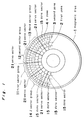
- Fig. 1 is a view for illustrating a basic format on the disc recording face in one concrete embodiment of a magnetic disc of the present invention.
- a disc plate 1 has a magnetic material filmed on the surface of a disc-shaped resin film medium like disc-shaped aluminum or glass base board or polyethylene terephthalate.
- the magnetic patterns of a format stored with a magnetic head cannot be directly seen, Fig. 1 shows the magnetic patterns described as visible.
- Many concentric circle-shaped tracks formed on the data recording face of the magnetic disc 1 are divided in a radial direction into K number of groups (zones).
- Numerals are given in order from the inner peripheral side so that a first zone, a second zone, a K zone are given as shown in 2, 3, 4.
- the K is made an integer.
- a plurality of tracks are included in each zone. Many sectors formed in the track are divided into J number of sector groups so that the they may become respectively equal respectively in angle in a circular direction.
- Numerals are given in order to provide a first sector group, a second sector group, a third sector group, a J sector group as shown in 11, 12, 13, 14.
- the j is made an integer.
- each sector group includes at least one data sector 15, with the respective data sector 15 includes, for example, 512 bytes of user data.
- Reference numerals 21 is a plurality of servo-sectors narrow in width disposed among the respective sector groups, with the J number of servo-sectors being provided on the full periphery.
- the servo-sectors are connected to an external peripheral zone of the magnetic disc from the internal peripheral zone and are arranged in approximately radial line direction.
- the servo-sector includes servo pattern signals necessary for servo- positioning heads.
- a positioning apparatus for positioning the heads debunchingly detect the servo-pattern signals embedded sporadically in the data sector groups so as to position in the selected track of the zone with a head being selected in accordance with the signal. This belongs to a system called a data face servo-system or an embedded servo- system.
- Fig. 2 is a further concrete embodiment of a magnetic disc of the present invention.
- a zone number K is 2
- a whole sector group number J is 28
- an integer M is 1
- the sector number of each sector group of a first zone 22 is 2
- the sector number of each sector group of the second zone 23 is 3, the number of one round servo-sector 21 is 28.
- Reference numeral 31 is a first sector group
- reference numeral 32 is a second sector group
- reference numeral 33 is a third sector group
- reference numeral 34 is a twenty eighth sector group.
- the whole track number is 320 with 220 being divided in the first zone, 100 in the second zone.
- the user data per sector is 51.2 bytes, so that the format of the user data of 10 megabytes is obtained on one side. Namely, 20 megabytes are obtained inside and outside of the disc.
- Fig. 3 is a still another embodiment of a magnetic disc of the preset invention.
- the number of one round of servo sector 21 remains the same as 28 as in the embodiment of Fig. 2 with the zone number K being 4, the whole sector group number J being 28, the M of an integer being 2.
- the sector number of the respective sector groups of the first zone 42 is 3, the sector number of the respective sector groups of the second zone 43 is 4, the sector number of the respective sector groups of the third zone 44 is 5, the sector number of the respective sector groups of the fourth zone 45 is 6.
- Reference numeral 51 is a first sector group
- reference numeral 52 is a second sector group
- reference numeral 53 is a third sector group
- reference numeral 54 is a twenty eighth sector group.
- the number of all the track is 320 with 60 being divided in a first zone, 70 in a second zone, 90 in a third zone, 100 in a fourth zone.
- the user data per sector is 512 bytes, and the format of the user data of 20 megabytes is obtained on one side. Namely, 40 megabytes on the surface and the reverse of the disc are obtained.
- the drawing does not show as it is diffuse.
- the user data per sector is 512 bytes with the track number being properly designed with the zone number K being 3, all the sector group number J being 28, the M of the integer being 2, and the format of the user data of 16 megabytes or more is obtained on one side. Namely, 32 megabytes or more are obtained inside and outside of the disc.
- the embodiment of the present invention shown in Fig. 2 and Fig. 3 is both constant in the servo sector number. If the track density (track pitch) is the same, the record capacity may be easily increased with the data face servo-control system and the positioning mechanism being as they are. Assume that the fixed servo-sector to be made permanent with the servo-sector and the data sector being separated in this manner is called a hard sector or a physical sector. Also, assume that a data sector which can make freely format independently of it is called a soft sector or a non-physical sector. Of course, the data sector of the soft sector can be freely designed. It is needless to say that the magnetic disc using the new magnetic material which makes it possible to render the record density higher for higher capacity. At the same time, the new magnetic head may be required. But a format writer apparatus (servo-writer apparatus), namely, an apparatus for writing servo-pattern signals into a raw disc may be used without being changed with respect to the increase in the record capacity.
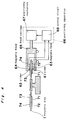
- Fig. 4 is a sectional view in one embodiment of a magnetic disc apparatus of the present invention.
- Reference numeral 1 is a magnetic disc
- reference numeral 61 is a slider with a magnetic head of the face on the side 0 side of the magnetic disc being embedded
- reference numeral 62 is a slider with a magnetic head on the face of the side 1 side being embedded in it, with the magnetic heads 63, 64 being provided respectively.
- Reference numeral 65 is a head carriage
- reference numeral 66 is a positioning apparatus including a positioning mechanism 67 for positioning on a selected track the magnetic head, and an electronic control circuit 68 for effecting the data face servo controlling
- reference numeral 69 is a spindle motor for rotating the magnetic disc.
- the electronic control circuit 68 obtains a control signal for positioning the magnetic heads 63, 64 in the track selected through extracting the servo-pattern signals from the debunching servo-sector so as to control the positioning mechanism 67.
- Reference numeral 71 shows a first zone of the face on the side 0 of the magnetic disc
- reference numeral 72 shows a first zone of the face of the side 1 of the magnetic disc
- reference numeral 73 shows a second zone.
- the magnetic disc apparatus shown in Fig. 4 in this manner can position a head in a selected optional track, no matter what format the data sector portion of the soft-sector is if the servo-sector is made hard, the number J is made constant.
- the magnetic disc if it is of one in example has the construction good in adaptability to the magnetic disc apparatus with the use of the flexible magnetic disc of a large capacity.
- the flexible magnetic disc is thin in medium
- the magnetic head on the side 0 and the side 1 causes magnetic interferences with each other
- the position of the head is slightly deviated in the radial direction of the disc.
- the position is deviated by 1.5mm.
- both the track position and the zone position are required to be deviated.
- the rift of the zone is desired to be almost the same radius because of the physical magnetic characteristic.
- the width (namely, the number of the tracks to be included in the zone) of the zone becomes different.
- the width of the first zone 71 on the side 0 is narrower in width than the first zone 73 on the side 1.
- the magnetic record characteristics may be improved in such a manner.
- the positioning operation may be simplified with heads being moved, accessed with high speeds astride or across the zone independently of the rift of the zone with the servo-detection time interval being almost constant.
- the record density is easy (to increase the number of the data sectors) to increase only in the data sector with the servo-sector being as it is even when the record capacity is increased with the adoption of the new magnetic material.
- the capacity increase may be easily effected with the data face servo-control and the positioning mechanism being as they are.
- the format writer apparatus namely, an apparatus for writing servo-pattern signals into the raw disc can be used without being changed.
Landscapes
- Engineering & Computer Science (AREA)
- Signal Processing (AREA)
- Signal Processing For Digital Recording And Reproducing (AREA)
- Moving Of The Head To Find And Align With The Track (AREA)
- Magnetic Record Carriers (AREA)
Abstract
Description
- The present invention generally relates to a magnetic disc and a magnetic disc apparatus for recording, reproducing data, and more particularly, a magnetic disc for obtaining large recording capacity with a special format, and a mass magnetic disc apparatus for recording, reproducing data on it.
- As a magnetic disc apparatus is capable of storing a large quantity of data, and accessing the data with high speeds with a random access system, it is widely spread as a data storage system. Unlike the tape apparatus, the data are recorded on the tracks of many concentric circles on the surface of the disc plate. The tracks on the internal peripheral side are shorter in length than the tracks on the external peripheral side, thus resulting in higher recording density as the tracks go towards the internal peripheries. On the other hand, as the external peripheral side is lower in the recording density, the possibility of further increasing the record capacity remains because of increased record density on the external peripheral side in terms of the magnetic recording operation.
- A hard disc apparatus including a positioning apparatus for taking in and out in the radial direction of the disc a disc assembly with many hard discs being stacked in the axial direction with the use of the hard disc having a magnetic material filmed on a disc shaped aluminum or a glass basic board, and a head carriage constructed with many magnetic heads being assembled respectively on each face of the disc are well known. In the hard disc apparatus, the specific one face of the stacked disc is not used for data writing, but is used for recording servo-pattern signals necessary for positioning the head carriage. The head is positioned in a selected track by the reproducing operation of the servo-pattern signal. This is called a servo-face servo-system or a dedicated servo system. As the data signal recording face and the servo-pattern signal recording face respectively exist independently in the hard disc apparatus of such a system, it is easy to position the head in an optional track, no matter how the format of each tack on the data signal recording face is constructed.
- As disclosed in, for example, USP 4,016,603 or in Japanese Patent Publication No. 59-901, tracks on many concentric circles on the data signal recording face are divided into some groups (zones) so as to increase the number of the data sectors as the tracks goes to the zone of the further external peripheral portion. In this manner, the recording density can be increased comparatively uniformly and within an allowable range. A problem if any is that as the revolution of the disc is constant, the peripheral speed is faster as the periphery becomes further external, the data transfer speed in the zone of the external periphery becomes higher. In recent years, as the processing speed of the electronic circuit has been improved considerably, it is adopted.
- In the hard disc apparatus with many discs being stacked as described hereinabove, it is easy to adopt such a format as to easily increase the data sector number of the zone of the external peripheral portion. But when the number of the discs is two or one, it is worse in efficiency to use one face thereof for the servo-pattern signal, so that the servo-face servo-system is hard to adopt.
- In a hard disc apparatus where the number of the discs is one only, a data face servo system is widely used which inserts (inserts a servo-sector of extremely narrow width) the servo-pattern signals between the data sector and the data sector, instead of a servo-face servo-system. This is called an embedded servo system. Namely, the system is a hybrid system of debunchingly dispersing onto the data signal reproducing face the servo-pattern signals necessary for positioning the head.
- The flexible magnetic disc apparatus using a magnetic disc having a magnetic membrane filmed on such a flexible medium as in polyethylene terephthalate or the like is a system most spread among magnetic disc apparatuses of an exchange type. Even in this case, a problem similar to a hard disc apparatus less in disc number is considered. Recently, the flexible magnetic disc is also made higher in capacity, especially the track density becomes made higher, the track pitch becomes made finer, so that a highly precise servo-positioning operation is made necessary. Therefore, even in the such mass flexible magnetic disc, the data face servo-system is adopted. This is disclosed in detail in, for example, Japanese Laid-Open Patent Application No. 63-173282.
- But as the servo-sector is grasped between data sectors in the above described data face servo-system, it is difficult to freely effect the data format. It is simple and convenient in the servo control to detect debunching servo-pattern signals for a constant sampling time (debunching time) no matter which position a head is located. Namely, the servo-pattern signal (servo-sector) of each track may be disposed at equal angle from the internal periphery of the disc to the external periphery. In other words, it is desirable to have the angle of the data sector formatted at equal angle across the whole periphery, so that it is incompatible with a method of increasing the number of the sectors as the periphery becomes further external.
- Japanese Laid-Open Patent Application No. 59-116911 shows one answer to the problem. Here the track is divided into a plurality of groups (zones), the number of the sectors is increased as many as the zone of the exterior periphery. Further, servo-sectors are inserted between the respective sector and sector. In this manner, the servo-sectors are not continuous towards the external periphery from the inner periphery, and the number thereof increases as many as the peripheral zones. Therefore, the servo-processing has a defect in that a more complicated sequence is required. Therefore, a servo-pattern signal is detected with a constant sampling time from the servo sector formatted at equal angle, with a disadvantage that the electronic control circuit becomes more complicated than the conventional data face servo system for effecting the servo control. It becomes difficult to move heads astride different zones with high speeds and to position it. This is because a sampling timing for detecting the servo-pattern signals is different or the sampling period is different among the different zones. Also, the different zone boundary cannot be positioned. Therefore, there is a defect in that the accessing time becomes longer.
- Accordingly, the present invention has been developed with a view to substantially eliminating the above discussed drawbacks inherent in the prior art. A first object of the present invention is to provide a magnetic disc and a magnetic disc apparatus which increase the sector number on the external periphery side more than the internal peripheral side so as to increase the recording capacity so that a simple data face servo system simple in interchangeable property.
- A second object of the present invention is to provide a magnetic disc and a magnetic disc apparatus which make a servo-sector a hard sector, make a data sector a soft sector, in other words, make the former a physical sector, make the latter a non-physical sector so as to respectively make them independent, and can freely design the format of the data sector without much restriction of the servo-sector.
- A third object of the present invention is to provide an efficient magnetic disc and magnetic disc apparatus provided with a data face servo-system capable of high speed accessing and positioning if the data sector number on the external peripheral side is more than on the internal peripheral side with a plurality of zones different in the data sector number being provided.
- A fourth object of the present invention is to provide a magnetic disc and a magnetic disc apparatus which is capable of capacity increase, with the data face servo-control and the positioning mechanism remaining the same with, for example, a mass flexible magnetic disc apparatus or the like.
- In accomplishing these and other objects, according to one preferred embodiment of the present invention, a magnetic disc of the present invention divides into a K number (K is an integer) of groups many concentric circle shaped data recording track formed on the data recording face of the magnetic disc, forms a K number of track groups in all from a first zone to a K zone towards the external periphery from the internal periphery, then divides many data sectors formed along the data record tracks into a J number (J an integer) so as to become approximately equal at angle in the circular direction, a J number of sector group with all, has one round J number of servo-sectors disposed among each sector group. Further, the servo-sector is adapted to include servo-pattern signals respectively, a sector number s including the respective sector groups of each track of a p zone is adapted to fill a formula show in the following equation.

- Also, the magnetic disc apparatus of the present invention is adapted to record, reproduce the above described magnetic disc. If the number J of the servo-sector is constant, such a magnetic head positioning apparatus as the magnetic head may be positioned in a selected track is provided if the number K of the track groups, and an integer M are different. The magnetic head positioning apparatus is composed of a positioning mechanism for moving a head carriage with at least two magnetic heads being amounted, and an electronic control circuit to be added to the above described positioning mechanism for obtaining a control signal for positioning a magnetic head in a track selected through extracting the servo-pattern signal from the servo-sector.
- The present invention of the above described construction is capable of increasing the record capacity without changing in the construction of the servo-sector, a coping operation can be effected with respect to the data face servo-control with processing, electronic control circuit as approximately simple as before.
- The servo-sector is connected in a radial shape towards the external periphery from the internal periphery of the magnetic disc, realizing the capacity increase with the data sector number of the external peripheral side zone being made more than the internal peripheral side, so that it is easy to access the head with high speed to position it, independently of the zone pause, with the servo detection time interval being almost constant.
- As the servo-sector is independent of the data sector, it is easy to increase the record density (to increase the number of the data sectors) only in the sector sector with the servo sector remaining as it is even when the record capacity is increased with the adoption of the new magnetic material or the like. Especially in the case of a mass flexible magnetic disc and flexible magnetic disc apparatus, it can easily increase the capacity with the data face servo-control and the positioning mechanism being as they are.
- Also, there is an economic advantage even in this case that a format writer apparatus (servo-writer apparatus), namely, an apparatus for writing servo-pattern signals in the raw disc may be used without being changed.
- These and other objects and features of the present invention will become apparent from the following description taken in conjunction with the preferred embodiment thereof with reference to the accompanying drawings, in which;
- Fig. 1 is a view for illustrating a basic format on the disc recording face in one concrete embodiment a magnetic disc of the present invention;
- Fig. 2 is a view of another concrete embodiment of a magnetic disc of the present invention;
- Fig. 3 is a view of still another embodiment of the magnetic disc of the present invention; and
- Fig. 4 is a sectional view in one embodiment of a magnetic disc apparatus of the present invention.
- Before the description of the present invention proceeds, it is to be noted that like parts are designated by like reference numerals throughout the accompanying drawings.
- An embodiment of the present invention will be described concretely with reference to the drawings. Fig. 1 is a view for illustrating a basic format on the disc recording face in one concrete embodiment of a magnetic disc of the present invention. A
disc plate 1 has a magnetic material filmed on the surface of a disc-shaped resin film medium like disc-shaped aluminum or glass base board or polyethylene terephthalate. The magnetic patterns of a format stored with a magnetic head cannot be directly seen, Fig. 1 shows the magnetic patterns described as visible. Many concentric circle-shaped tracks formed on the data recording face of themagnetic disc 1 are divided in a radial direction into K number of groups (zones). Numerals are given in order from the inner peripheral side so that a first zone, a second zone, a K zone are given as shown in 2, 3, 4. Here the K is made an integer. A plurality of tracks are included in each zone. Many sectors formed in the track are divided into J number of sector groups so that the they may become respectively equal respectively in angle in a circular direction. Numerals are given in order to provide a first sector group, a second sector group, a third sector group, a J sector group as shown in 11, 12, 13, 14. Here the j is made an integer. Assume that each sector group includes at least onedata sector 15, with therespective data sector 15 includes, for example, 512 bytes of user data.Reference numerals 21 is a plurality of servo-sectors narrow in width disposed among the respective sector groups, with the J number of servo-sectors being provided on the full periphery. The servo-sectors are connected to an external peripheral zone of the magnetic disc from the internal peripheral zone and are arranged in approximately radial line direction. The servo-sector includes servo pattern signals necessary for servo- positioning heads. A positioning apparatus for positioning the heads debunchingly detect the servo-pattern signals embedded sporadically in the data sector groups so as to position in the selected track of the zone with a head being selected in accordance with the signal. This belongs to a system called a data face servo-system or an embedded servo- system. - Here a sector number s to be included in each sector group of each track of a p zone is assumed to fill a formula shown in the following equation, where the following M is an integer.

- Fig. 2 is a further concrete embodiment of a magnetic disc of the present invention. In Fig. 1, a zone number K is 2, a whole sector group number J is 28, an integer M is 1, the sector number of each sector group of a
first zone 22 is 2, the sector number of each sector group of thesecond zone 23 is 3, the number of one round servo-sector 21 is 28.Reference numeral 31 is a first sector group,reference numeral 32 is a second sector group,reference numeral 33 is a third sector group,reference numeral 34 is a twenty eighth sector group. Here the whole track number is 320 with 220 being divided in the first zone, 100 in the second zone. Assume that the user data per sector is 51.2 bytes, so that the format of the user data of 10 megabytes is obtained on one side. Namely, 20 megabytes are obtained inside and outside of the disc. - Fig. 3 is a still another embodiment of a magnetic disc of the preset invention. In Fig. 1, the number of one round of
servo sector 21 remains the same as 28 as in the embodiment of Fig. 2 with the zone number K being 4, the whole sector group number J being 28, the M of an integer being 2. But the sector number of the respective sector groups of thefirst zone 42 is 3, the sector number of the respective sector groups of thesecond zone 43 is 4, the sector number of the respective sector groups of thethird zone 44 is 5, the sector number of the respective sector groups of thefourth zone 45 is 6.Reference numeral 51 is a first sector group,reference numeral 52 is a second sector group,reference numeral 53 is a third sector group,reference numeral 54 is a twenty eighth sector group. Assume here that the number of all the track is 320 with 60 being divided in a first zone, 70 in a second zone, 90 in a third zone, 100 in a fourth zone. Assume that the user data per sector is 512 bytes, and the format of the user data of 20 megabytes is obtained on one side. Namely, 40 megabytes on the surface and the reverse of the disc are obtained. - The drawing does not show as it is diffuse. Assume that the user data per sector is 512 bytes with the track number being properly designed with the zone number K being 3, all the sector group number J being 28, the M of the integer being 2, and the format of the user data of 16 megabytes or more is obtained on one side. Namely, 32 megabytes or more are obtained inside and outside of the disc.
- The embodiment of the present invention shown in Fig. 2 and Fig. 3 is both constant in the servo sector number. If the track density (track pitch) is the same, the record capacity may be easily increased with the data face servo-control system and the positioning mechanism being as they are. Assume that the fixed servo-sector to be made permanent with the servo-sector and the data sector being separated in this manner is called a hard sector or a physical sector. Also, assume that a data sector which can make freely format independently of it is called a soft sector or a non-physical sector. Of course, the data sector of the soft sector can be freely designed. It is needless to say that the magnetic disc using the new magnetic material which makes it possible to render the record density higher for higher capacity. At the same time, the new magnetic head may be required. But a format writer apparatus (servo-writer apparatus), namely, an apparatus for writing servo-pattern signals into a raw disc may be used without being changed with respect to the increase in the record capacity.
- Fig. 4 is a sectional view in one embodiment of a magnetic disc apparatus of the present invention.
Reference numeral 1 is a magnetic disc,reference numeral 61 is a slider with a magnetic head of the face on the side 0 side of the magnetic disc being embedded,reference numeral 62 is a slider with a magnetic head on the face of theside 1 side being embedded in it, with themagnetic heads Reference numeral 65 is a head carriage, reference numeral 66 is a positioning apparatus including apositioning mechanism 67 for positioning on a selected track the magnetic head, and anelectronic control circuit 68 for effecting the data face servo controlling, reference numeral 69 is a spindle motor for rotating the magnetic disc. Theelectronic control circuit 68 obtains a control signal for positioning themagnetic heads positioning mechanism 67.Reference numeral 71 shows a first zone of the face on the side 0 of the magnetic disc,reference numeral 72 shows a first zone of the face of theside 1 of the magnetic disc,reference numeral 73 shows a second zone. The magnetic disc apparatus shown in Fig. 4 in this manner can position a head in a selected optional track, no matter what format the data sector portion of the soft-sector is if the servo-sector is made hard, the number J is made constant. - In the embodiment of the present invention in Fig. 4, the magnetic disc if it is of one in example has the construction good in adaptability to the magnetic disc apparatus with the use of the flexible magnetic disc of a large capacity. Namely, as the flexible magnetic disc is thin in medium, the magnetic head on the side 0 and the
side 1 causes magnetic interferences with each other, the position of the head is slightly deviated in the radial direction of the disc. In the flexible magnetic disc apparatus of the normal 3.5 inches, the position is deviated by 1.5mm. Accordingly, on the side 0 and theside 1 of the disc, both the track position and the zone position are required to be deviated. The rift of the zone is desired to be almost the same radius because of the physical magnetic characteristic. Thus, in the side 0 and theside 1, the width (namely, the number of the tracks to be included in the zone) of the zone becomes different. In Fig. 4, the width of thefirst zone 71 on the side 0 is narrower in width than thefirst zone 73 on theside 1. The magnetic record characteristics may be improved in such a manner. - As is clear from the foregoing description, according to the arrangement of the present invention, such an effect as described hereinabove can be obtained. Even in a case where the increase in the record capacity may be provided, the completely same data face servo-control may be utilized and the processing, the electronic circuit as simple in degree as before can be used.
- As the servo-sectors are connected radially from the internal periphery of the magnetic disc to the external periphery, realizing the capacity increase with the data sector number of the external peripheral side zone being made more than the zone of the internal peripheral side, the positioning operation may be simplified with heads being moved, accessed with high speeds astride or across the zone independently of the rift of the zone with the servo-detection time interval being almost constant.
- As the servo-sector and the data sector are independent, the record density is easy (to increase the number of the data sectors) to increase only in the data sector with the servo-sector being as it is even when the record capacity is increased with the adoption of the new magnetic material. Especially, in a case of a mass flexible magnetic disc and flexible magnetic disc apparatus, the capacity increase may be easily effected with the data face servo-control and the positioning mechanism being as they are.
- Also, even in this case, there is an economic advantage in that the format writer apparatus (servo-writer apparatus), namely, an apparatus for writing servo-pattern signals into the raw disc can be used without being changed.
- Although the present invention has been fully described by way of example with reference to the accompanying drawings, it is to be noted here that various changes and modifications will be apparent to those skilled in the art. Therefore, unless otherwise much changes and modifications depart from the scope of the present invention, they should be construed as included therein.
Claims (8)
- A magnetic disc comprising many concentric circular data record tracks formed on the data recoding face of a magnetic disc, a K number of tracks group in all from a first zone to a K zone towards the external periphery from the internal periphery, with the data recording track being divided into the group of a K number (K is an integer), many data sectors formed along the data record track, a J number of sector group in all divided into the J number (J is an integer) so that the data sectors may become approximately equal in angle in the circular direction, one round J number of servo-sectors disposed among each sector group. Further, servo-pattern signals to be included in the servo-sector, a sector number s including the respective sector groups of each track of a p zone is adapted to fill a formula shown in the following equation.

where M is an integer. - A magnetic disc described in accordance with the claim 1, where the arrangement of many concentric circle-shaped data record tracks formed on the data record face and a K number of track group is different in radium in the surface and the reverse of the magnetic disc.
- A magnetic disc described in accordance with the claim 1, where the number of the concentric circle-shaped data record tracks to be included in the track group of a p zone is different in the surface and the reverse of the magnetic disc.
- A magnetic disc described in accordance with the claim 1, where K is 2, J is 28, M is 1.
- A magnetic disc described in accordance with the claim 1, where K is 3, J is 28, M is 2.
- A magnetic disc described in accordance with the claim 1, where K is 4, J is 28, M is 2.
- A magnetic disc apparatus for recording, reproducing a magnetic disc to be restricted to the claim 1 where a magnetic disc apparatus is provided with such a magnetic head positioning apparatus as can position a magnetic head in a selected track even if the number K of a track group and an integer M are different if the number J of the servo sectors is constant, the magnetic head positioning apparatus is composed of a positioning mechanism for moving a head carriage with at least two magnetic heads being amounted, and an electronic control circuit to be added to the positioning mechanism for obtaining a control signal for positioning a magnetic head in a track selected through extracting the servo-pattern signal from the servo-sector.
- A magnetic disc apparatus described in accordance with the claim 7, where a magnetic disc apparatus is restricted in the claim 1 so as to record, reproduce the exchangeable and flexible magnetic disc, is provided with at least two magnetic heads with respect to both the faces of the above described magnetic disc, these heads being slipped with respect to each other in the radius direction of the above described magnetic disc.
Applications Claiming Priority (2)
| Application Number | Priority Date | Filing Date | Title |
|---|---|---|---|
| JP2403059A JP2596222B2 (en) | 1990-12-18 | 1990-12-18 | Magnetic disk and magnetic disk device |
| JP403059/90 | 1990-12-18 |
Publications (2)
| Publication Number | Publication Date |
|---|---|
| EP0491264A1 true EP0491264A1 (en) | 1992-06-24 |
| EP0491264B1 EP0491264B1 (en) | 1996-06-12 |
Family
ID=18512809
Family Applications (1)
| Application Number | Title | Priority Date | Filing Date |
|---|---|---|---|
| EP91121139A Expired - Lifetime EP0491264B1 (en) | 1990-12-18 | 1991-12-10 | Magnetic disc |
Country Status (4)
| Country | Link |
|---|---|
| EP (1) | EP0491264B1 (en) |
| JP (1) | JP2596222B2 (en) |
| KR (1) | KR950013832B1 (en) |
| DE (1) | DE69120227T2 (en) |
Cited By (3)
| Publication number | Priority date | Publication date | Assignee | Title |
|---|---|---|---|---|
| EP0577214A2 (en) * | 1992-07-03 | 1994-01-05 | Koninklijke Philips Electronics N.V. | Zoned record carrier |
| EP0595249A2 (en) * | 1992-10-27 | 1994-05-04 | Nec Corporation | Magnetic disk controller capable of avoiding erroneous write operation |
| GB2297419A (en) * | 1995-01-26 | 1996-07-31 | Alps Electric Co Ltd | Disk medium and method of writing data onto the disk medium |
Families Citing this family (1)
| Publication number | Priority date | Publication date | Assignee | Title |
|---|---|---|---|---|
| JP2943837B2 (en) * | 1994-03-15 | 1999-08-30 | 富士通株式会社 | Magnetic disk drive using data surface servo method |
Citations (3)
| Publication number | Priority date | Publication date | Assignee | Title |
|---|---|---|---|---|
| US4016603A (en) * | 1975-05-30 | 1977-04-05 | International Business Machines Corporation | Disk storage apparatus having signals recorded in a specific format |
| EP0181020A1 (en) * | 1984-10-22 | 1986-05-14 | Koninklijke Philips Electronics N.V. | Apparatus for reproducing information from a record carrier |
| EP0327207A2 (en) * | 1988-02-03 | 1989-08-09 | International Business Machines Corporation | A method of writing a sector servo pattern for a record disk storage device |
-
1990
- 1990-12-18 JP JP2403059A patent/JP2596222B2/en not_active Expired - Fee Related
-
1991
- 1991-12-10 DE DE69120227T patent/DE69120227T2/en not_active Expired - Fee Related
- 1991-12-10 EP EP91121139A patent/EP0491264B1/en not_active Expired - Lifetime
- 1991-12-18 KR KR1019910023308A patent/KR950013832B1/en not_active IP Right Cessation
Patent Citations (3)
| Publication number | Priority date | Publication date | Assignee | Title |
|---|---|---|---|---|
| US4016603A (en) * | 1975-05-30 | 1977-04-05 | International Business Machines Corporation | Disk storage apparatus having signals recorded in a specific format |
| EP0181020A1 (en) * | 1984-10-22 | 1986-05-14 | Koninklijke Philips Electronics N.V. | Apparatus for reproducing information from a record carrier |
| EP0327207A2 (en) * | 1988-02-03 | 1989-08-09 | International Business Machines Corporation | A method of writing a sector servo pattern for a record disk storage device |
Cited By (8)
| Publication number | Priority date | Publication date | Assignee | Title |
|---|---|---|---|---|
| EP0577214A2 (en) * | 1992-07-03 | 1994-01-05 | Koninklijke Philips Electronics N.V. | Zoned record carrier |
| EP0577214A3 (en) * | 1992-07-03 | 1994-07-27 | Philips Electronics Nv | Zoned record carrier |
| EP0595249A2 (en) * | 1992-10-27 | 1994-05-04 | Nec Corporation | Magnetic disk controller capable of avoiding erroneous write operation |
| EP0595249A3 (en) * | 1992-10-27 | 1995-12-06 | Nec Corp | Magnetic disk controller capable of avoiding erroneous write operation |
| US5559647A (en) * | 1992-10-27 | 1996-09-24 | Nec Corporation | Magnetic disk controller which avoids erroneous write operations to ZBR-type magnetic disks upon detection of a next sector mark from the ZBR magnetic disk |
| US5654835A (en) * | 1992-10-27 | 1997-08-05 | Nec Corporation | Magnetic disk controller capable of avoiding erroneous write operations to ZBR-type magnetic disks |
| GB2297419A (en) * | 1995-01-26 | 1996-07-31 | Alps Electric Co Ltd | Disk medium and method of writing data onto the disk medium |
| GB2297419B (en) * | 1995-01-26 | 1998-09-23 | Alps Electric Co Ltd | Disk medium and method of writing data onto the disk medium |
Also Published As
| Publication number | Publication date |
|---|---|
| KR920013390A (en) | 1992-07-29 |
| EP0491264B1 (en) | 1996-06-12 |
| DE69120227D1 (en) | 1996-07-18 |
| JP2596222B2 (en) | 1997-04-02 |
| DE69120227T2 (en) | 1996-10-10 |
| KR950013832B1 (en) | 1995-11-16 |
| JPH04313866A (en) | 1992-11-05 |
Similar Documents
| Publication | Publication Date | Title |
|---|---|---|
| EP0080256B1 (en) | Information recording/reproducing apparatus | |
| JP2685090B2 (en) | Manufacturing method including formatting a disk medium for a disk drive device | |
| EP0186662B1 (en) | Self-timed runout correction pattern | |
| US5771126A (en) | Hard disk drive with reduced sized servo sectors and driving method therefor | |
| US4984103A (en) | Method for reading/writing for a floppy disc drive with buffer memory | |
| KR970705813A (en) | A data track pattern including a built-in servo sector for a magnetoresistive head structure for a disk drive (Data Track Pattern Including Embedded Servo Sector for a Magnetoresistive Head Structure for a Disk Drive) | |
| EP0390601A3 (en) | Information recording disk, and information record/reproducing method and apparatus utilizing the same | |
| KR960001252B1 (en) | Transducer head skew arrangement for disk drive system | |
| US4918972A (en) | Dual reference track scheme | |
| US5600623A (en) | Disc device having a plurality of heads each movable within a limited distance | |
| EP0491264B1 (en) | Magnetic disc | |
| JPS59116911A (en) | Magnetic disc | |
| US4977471A (en) | Method for servo formatting disc media for a floppy disk drive | |
| US4876618A (en) | Method for detecting zero track | |
| EP0459726A2 (en) | Magnetic disk apparatus | |
| KR100505576B1 (en) | Hard disk drive having hard disk recorded table information according to model | |
| US4942484A (en) | Floppy disk drive with closed loop servoed high density read/write gap, and with low density read/write gap for the write updating of standard open loop formatted medium | |
| JPH04102267A (en) | Hard disk device | |
| US5850381A (en) | Method of recording information on a disc by recording information at interleaved sectors | |
| JPS63136357A (en) | Rotating speed control method | |
| WO1991001554A1 (en) | Zone servo sector format alignment scheme for servo and spindle motor control | |
| KR100293561B1 (en) | Discontinuous sector type disc | |
| JPH01220101A (en) | Moving multi-track head type information recorder | |
| JPH0462121B2 (en) | ||
| JPH0487075A (en) | Signal recording method for magnetic disk device |
Legal Events
| Date | Code | Title | Description |
|---|---|---|---|
| PUAI | Public reference made under article 153(3) epc to a published international application that has entered the european phase |
Free format text: ORIGINAL CODE: 0009012 |
|
| 17P | Request for examination filed |
Effective date: 19911210 |
|
| AK | Designated contracting states |
Kind code of ref document: A1 Designated state(s): DE FR GB IT NL |
|
| 17Q | First examination report despatched |
Effective date: 19941223 |
|
| GRAH | Despatch of communication of intention to grant a patent |
Free format text: ORIGINAL CODE: EPIDOS IGRA |
|
| GRAH | Despatch of communication of intention to grant a patent |
Free format text: ORIGINAL CODE: EPIDOS IGRA |
|
| GRAA | (expected) grant |
Free format text: ORIGINAL CODE: 0009210 |
|
| AK | Designated contracting states |
Kind code of ref document: B1 Designated state(s): DE FR GB IT NL |
|
| PG25 | Lapsed in a contracting state [announced via postgrant information from national office to epo] |
Ref country code: IT Free format text: LAPSE BECAUSE OF FAILURE TO SUBMIT A TRANSLATION OF THE DESCRIPTION OR TO PAY THE FEE WITHIN THE PRE;WARNING: LAPSES OF ITALIAN PATENTS WITH EFFECTIVE DATE BEFORE 2007 MAY HAVE OCCURRED AT ANY TIME BEFORE 2007. THE CORRECT EFFECTIVE DATE MAY BE DIFFERENT FROM THE ONE RECORDED.SCRIBED TIME-LIMIT Effective date: 19960612 Ref country code: FR Effective date: 19960612 |
|
| REF | Corresponds to: |
Ref document number: 69120227 Country of ref document: DE Date of ref document: 19960718 |
|
| EN | Fr: translation not filed | ||
| PLBE | No opposition filed within time limit |
Free format text: ORIGINAL CODE: 0009261 |
|
| STAA | Information on the status of an ep patent application or granted ep patent |
Free format text: STATUS: NO OPPOSITION FILED WITHIN TIME LIMIT |
|
| 26N | No opposition filed | ||
| REG | Reference to a national code |
Ref country code: GB Ref legal event code: IF02 |
|
| PGFP | Annual fee paid to national office [announced via postgrant information from national office to epo] |
Ref country code: GB Payment date: 20051207 Year of fee payment: 15 |
|
| PGFP | Annual fee paid to national office [announced via postgrant information from national office to epo] |
Ref country code: DE Payment date: 20051209 Year of fee payment: 15 |
|
| PGFP | Annual fee paid to national office [announced via postgrant information from national office to epo] |
Ref country code: NL Payment date: 20051215 Year of fee payment: 15 |
|
| PG25 | Lapsed in a contracting state [announced via postgrant information from national office to epo] |
Ref country code: NL Free format text: LAPSE BECAUSE OF NON-PAYMENT OF DUE FEES Effective date: 20070701 |
|
| PG25 | Lapsed in a contracting state [announced via postgrant information from national office to epo] |
Ref country code: DE Free format text: LAPSE BECAUSE OF NON-PAYMENT OF DUE FEES Effective date: 20070703 |
|
| GBPC | Gb: european patent ceased through non-payment of renewal fee |
Effective date: 20061210 |
|
| NLV4 | Nl: lapsed or anulled due to non-payment of the annual fee |
Effective date: 20070701 |
|
| PG25 | Lapsed in a contracting state [announced via postgrant information from national office to epo] |
Ref country code: GB Free format text: LAPSE BECAUSE OF NON-PAYMENT OF DUE FEES Effective date: 20061210 |