EP0490088B1 - Circuit for the electronic control of an internal combustion engine - Google Patents
Circuit for the electronic control of an internal combustion engine Download PDFInfo
- Publication number
- EP0490088B1 EP0490088B1 EP91119124A EP91119124A EP0490088B1 EP 0490088 B1 EP0490088 B1 EP 0490088B1 EP 91119124 A EP91119124 A EP 91119124A EP 91119124 A EP91119124 A EP 91119124A EP 0490088 B1 EP0490088 B1 EP 0490088B1
- Authority
- EP
- European Patent Office
- Prior art keywords
- engine
- input
- switching arrangement
- arrangement according
- control module
- Prior art date
- Legal status (The legal status is an assumption and is not a legal conclusion. Google has not performed a legal analysis and makes no representation as to the accuracy of the status listed.)
- Expired - Lifetime
Links
Images
Classifications
-
- F—MECHANICAL ENGINEERING; LIGHTING; HEATING; WEAPONS; BLASTING
- F02—COMBUSTION ENGINES; HOT-GAS OR COMBUSTION-PRODUCT ENGINE PLANTS
- F02D—CONTROLLING COMBUSTION ENGINES
- F02D41/00—Electrical control of supply of combustible mixture or its constituents
- F02D41/009—Electrical control of supply of combustible mixture or its constituents using means for generating position or synchronisation signals
-
- F—MECHANICAL ENGINEERING; LIGHTING; HEATING; WEAPONS; BLASTING
- F02—COMBUSTION ENGINES; HOT-GAS OR COMBUSTION-PRODUCT ENGINE PLANTS
- F02D—CONTROLLING COMBUSTION ENGINES
- F02D41/00—Electrical control of supply of combustible mixture or its constituents
- F02D41/30—Controlling fuel injection
- F02D41/32—Controlling fuel injection of the low pressure type
- F02D41/34—Controlling fuel injection of the low pressure type with means for controlling injection timing or duration
-
- F—MECHANICAL ENGINEERING; LIGHTING; HEATING; WEAPONS; BLASTING
- F02—COMBUSTION ENGINES; HOT-GAS OR COMBUSTION-PRODUCT ENGINE PLANTS
- F02P—IGNITION, OTHER THAN COMPRESSION IGNITION, FOR INTERNAL-COMBUSTION ENGINES; TESTING OF IGNITION TIMING IN COMPRESSION-IGNITION ENGINES
- F02P15/00—Electric spark ignition having characteristics not provided for in, or of interest apart from, groups F02P1/00 - F02P13/00 and combined with layout of ignition circuits
- F02P15/10—Electric spark ignition having characteristics not provided for in, or of interest apart from, groups F02P1/00 - F02P13/00 and combined with layout of ignition circuits having continuous electric sparks
-
- F—MECHANICAL ENGINEERING; LIGHTING; HEATING; WEAPONS; BLASTING
- F02—COMBUSTION ENGINES; HOT-GAS OR COMBUSTION-PRODUCT ENGINE PLANTS
- F02P—IGNITION, OTHER THAN COMPRESSION IGNITION, FOR INTERNAL-COMBUSTION ENGINES; TESTING OF IGNITION TIMING IN COMPRESSION-IGNITION ENGINES
- F02P15/00—Electric spark ignition having characteristics not provided for in, or of interest apart from, groups F02P1/00 - F02P13/00 and combined with layout of ignition circuits
- F02P15/12—Electric spark ignition having characteristics not provided for in, or of interest apart from, groups F02P1/00 - F02P13/00 and combined with layout of ignition circuits having means for strengthening spark during starting
-
- F—MECHANICAL ENGINEERING; LIGHTING; HEATING; WEAPONS; BLASTING
- F02—COMBUSTION ENGINES; HOT-GAS OR COMBUSTION-PRODUCT ENGINE PLANTS
- F02P—IGNITION, OTHER THAN COMPRESSION IGNITION, FOR INTERNAL-COMBUSTION ENGINES; TESTING OF IGNITION TIMING IN COMPRESSION-IGNITION ENGINES
- F02P5/00—Advancing or retarding ignition; Control therefor
- F02P5/04—Advancing or retarding ignition; Control therefor automatically, as a function of the working conditions of the engine or vehicle or of the atmospheric conditions
- F02P5/145—Advancing or retarding ignition; Control therefor automatically, as a function of the working conditions of the engine or vehicle or of the atmospheric conditions using electrical means
- F02P5/15—Digital data processing
- F02P5/1502—Digital data processing using one central computing unit
- F02P5/1506—Digital data processing using one central computing unit with particular means during starting
-
- F—MECHANICAL ENGINEERING; LIGHTING; HEATING; WEAPONS; BLASTING
- F02—COMBUSTION ENGINES; HOT-GAS OR COMBUSTION-PRODUCT ENGINE PLANTS
- F02P—IGNITION, OTHER THAN COMPRESSION IGNITION, FOR INTERNAL-COMBUSTION ENGINES; TESTING OF IGNITION TIMING IN COMPRESSION-IGNITION ENGINES
- F02P7/00—Arrangements of distributors, circuit-makers or -breakers, e.g. of distributor and circuit-breaker combinations or pick-up devices
- F02P7/02—Arrangements of distributors, circuit-makers or -breakers, e.g. of distributor and circuit-breaker combinations or pick-up devices of distributors
- F02P7/03—Arrangements of distributors, circuit-makers or -breakers, e.g. of distributor and circuit-breaker combinations or pick-up devices of distributors with electrical means
- F02P7/035—Arrangements of distributors, circuit-makers or -breakers, e.g. of distributor and circuit-breaker combinations or pick-up devices of distributors with electrical means without mechanical switching means
-
- F—MECHANICAL ENGINEERING; LIGHTING; HEATING; WEAPONS; BLASTING
- F02—COMBUSTION ENGINES; HOT-GAS OR COMBUSTION-PRODUCT ENGINE PLANTS
- F02P—IGNITION, OTHER THAN COMPRESSION IGNITION, FOR INTERNAL-COMBUSTION ENGINES; TESTING OF IGNITION TIMING IN COMPRESSION-IGNITION ENGINES
- F02P7/00—Arrangements of distributors, circuit-makers or -breakers, e.g. of distributor and circuit-breaker combinations or pick-up devices
- F02P7/06—Arrangements of distributors, circuit-makers or -breakers, e.g. of distributor and circuit-breaker combinations or pick-up devices of circuit-makers or -breakers, or pick-up devices adapted to sense particular points of the timing cycle
- F02P7/077—Circuits therefor, e.g. pulse generators
- F02P7/0775—Electronical verniers
-
- F—MECHANICAL ENGINEERING; LIGHTING; HEATING; WEAPONS; BLASTING
- F02—COMBUSTION ENGINES; HOT-GAS OR COMBUSTION-PRODUCT ENGINE PLANTS
- F02B—INTERNAL-COMBUSTION PISTON ENGINES; COMBUSTION ENGINES IN GENERAL
- F02B2275/00—Other engines, components or details, not provided for in other groups of this subclass
- F02B2275/14—Direct injection into combustion chamber
-
- F—MECHANICAL ENGINEERING; LIGHTING; HEATING; WEAPONS; BLASTING
- F02—COMBUSTION ENGINES; HOT-GAS OR COMBUSTION-PRODUCT ENGINE PLANTS
- F02N—STARTING OF COMBUSTION ENGINES; STARTING AIDS FOR SUCH ENGINES, NOT OTHERWISE PROVIDED FOR
- F02N99/00—Subject matter not provided for in other groups of this subclass
- F02N99/002—Starting combustion engines by ignition means
-
- Y—GENERAL TAGGING OF NEW TECHNOLOGICAL DEVELOPMENTS; GENERAL TAGGING OF CROSS-SECTIONAL TECHNOLOGIES SPANNING OVER SEVERAL SECTIONS OF THE IPC; TECHNICAL SUBJECTS COVERED BY FORMER USPC CROSS-REFERENCE ART COLLECTIONS [XRACs] AND DIGESTS
- Y02—TECHNOLOGIES OR APPLICATIONS FOR MITIGATION OR ADAPTATION AGAINST CLIMATE CHANGE
- Y02T—CLIMATE CHANGE MITIGATION TECHNOLOGIES RELATED TO TRANSPORTATION
- Y02T10/00—Road transport of goods or passengers
- Y02T10/10—Internal combustion engine [ICE] based vehicles
- Y02T10/12—Improving ICE efficiencies
-
- Y—GENERAL TAGGING OF NEW TECHNOLOGICAL DEVELOPMENTS; GENERAL TAGGING OF CROSS-SECTIONAL TECHNOLOGIES SPANNING OVER SEVERAL SECTIONS OF THE IPC; TECHNICAL SUBJECTS COVERED BY FORMER USPC CROSS-REFERENCE ART COLLECTIONS [XRACs] AND DIGESTS
- Y02—TECHNOLOGIES OR APPLICATIONS FOR MITIGATION OR ADAPTATION AGAINST CLIMATE CHANGE
- Y02T—CLIMATE CHANGE MITIGATION TECHNOLOGIES RELATED TO TRANSPORTATION
- Y02T10/00—Road transport of goods or passengers
- Y02T10/10—Internal combustion engine [ICE] based vehicles
- Y02T10/40—Engine management systems
Definitions
- the invention relates to a circuit arrangement for the electronic control of an internal combustion engine according to the preamble of patent claim 1.
- Also known from DE 35 37 000 is the use of a coding disk which is provided with a Gray code and a sensor which scans the coding disk for the static detection of the load detection determined for the ignition triggering in a constant pressure carburetor.
- DE-OS 36 30 272 devices for controlling an internal combustion engine are known, in which the position of a sensor disk connected to a shaft of the internal combustion engine and having a perforation designed as a marking is registered by a spatially fixed receiving segment.
- a disadvantage of these known control devices is that they only allow the control of a single controlled variable (e.g. the ignition trigger).
- DE 36 09 070 A1 describes an electronic control system for internal combustion engines in which two central processing units connected to one another by transmission lines are supplied on the input side with individual variables which characterize the engine state.
- a central unit is supplied with motor rotation parameters which correspond to a predetermined crank angle position and which are detected by a scanning device.
- a scanning sensor generates a reference crank angle signal which corresponds to a predetermined fixed crank angle position of an individual engine cylinder, whereby in particular only relative crank angle positions can be determined.
- the invention has for its object to provide an electronic control for internal combustion engines, which avoids the above-mentioned shortcomings, has a high operational reliability and is inexpensive to manufacture.
- a circuit arrangement according to the invention for internal combustion engines has as essential components an electronic control unit (computer), an absolute angle generator, an engine stop detection circuit, an ignition sequence circuit and a valve control device.
- the control of the electrical functions of the ignition sequence circuit and the valve control device is carried out by the electronic control unit.
- the computer is supplied by the absolute value angle sensor, which detects the crankshaft angle in the dynamic and static state, with electrical signals which are processed by means of signal shaping modules and which represent controlled variables.
- the control unit is supplied with electrical signals from the absolute value angle encoder and the valve control, by means of which the angle encoder code and the valve work sequence are monitored.
- the absolute angle encoder consists of one on one Crankshaft-mounted wheel that carries a clearly identifiable code on its surface, which is scanned by a sensor.
- the scanning by the sensor takes place, for. B. inductive or optical.
- a one-step 9-bit Gray code which enables the crankshaft angle position to be determined with an accuracy of 0.7 °, is preferably used for the coding disk (wheel).
- the code patterns of the individual tracks of the coding disk are scanned simultaneously by means of a multifunction sensor with integrated electronics and converted into electrical signals that are processed for further processing. These electronically processed signals are sequentially fed to the control unit via a parallel serial interface (parallel series converter).
- the input of the motor standstill detection circuit is connected to the input of the least significant bit of the parallel series converter.
- the input signal is electronically differentiated and fed to a counter which, in the absence of a signal on the input side, generates a signal corresponding to the motor state (standstill or operation) on the output side, which signal is fed to the control unit.
- the simultaneous electronic evaluation of all (9 bit) code tracks and a single code track, namely the least significant (1st bit) is thus advantageously possible by means of a fast-working engine standstill detection circuit and, in addition, by means of a high-resolution determination of the crankshaft angle in the control unit.
- the control unit uses the electrical signals supplied to the control unit by the engine standstill detection circuit and the absolute value angle transmitter to inject individual injection valves, intake valves, Exhaust valves and spark plugs controlled, each consisting of an electrical switch and a z.
- the sequence of the sequential activation of the individual modules depends on the total number of cylinders of the internal combustion engine and the cylinder work cycles. According to a subdivision of the cylinder working cycles into an ignition, cylinder closing and cylinder opening sequence, a crankshaft revolution with half the number of cylinders is divided equally, e.g. B.
- the sectors are switched over to the other cylinder group after a crankshaft revolution by means of a flip-flop circuit.
- the ignition takes place in cylinders 1, 2 and 3 during the first revolution and in cylinders 4, 5 and 6 during the second revolution.
- the valve actuation takes place analogously to this ignition sequence. It is advantageous that with such a division into three 120 ° sectors, the ignition timing and also the ignition duration can be precisely adapted to the current engine requirements.
- the electrically controlled inlet, Exhaust and injection valves can also be controlled sequentially when the engine is started, which reduces electrical power consumption.
- the proposal of the intake, exhaust and injection valves and the ignition modules, which are not mechanically coupled to one another without a camshaft, enables two-stroke operation to be avoided while avoiding the known disadvantages.
- the change in cylinder charge, i. H. the flushing takes place by simultaneously and briefly opening the inlet and outlet valves, which results in a forced flushing with air.
- fuel is injected into the cylinder using the injection valves.
- the inlet pressure determines the phase position for flushing the piston position.
- the inlet pressure can be chosen so high that it corresponds to the cylinder internal pressure at top dead center, which means that forced purging can be dispensed with.
- the exhaust gas is emitted almost during the entire second cycle, whereas the cylinder is only supplied with fuel before top dead center. This enables flexible adaptation to the special engine requirements such as engine torque, engine power, fuel parameters and mixture composition.
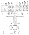
- the circuit for the electronic control of the internal combustion engine comprises a central control unit 2, an absolute value encoder 4, an electronic control program memory 6, an engine standstill detection circuit 5 shown in FIG. 15 and ignition modules 16, 17.
- All of the modules 10 to 17 are controlled by the control unit 2 as a function of the instantaneous operating parameters of the internal combustion engine, which are supplied to the control unit 2 by the absolute value angle encoder 4 and additional sensors that measure the operating parameters of the internal combustion engine via data lines 7.
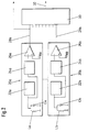
- the absolute value angle encoder 4 consists of a total of nine signal shaping modules, of which only two 20a, 20b are shown in FIG. 2.
- the signal shaping modules 20a, 20b each have a parallel resonant circuit consisting of an inductor La or Lb and a capacitor Ca or Cb, an oscillator 22a or 22b and a demodulator 24a or 24b connected in series with the parallel resonant circuit, the output of the Demodulator 24a or 24b is connected to the inverting input of a comparator 26a or 26b.
- the comparator 26a or 26b In cooperation with a reference voltage U RA or U RB present at the non-inverting input of the comparator 26a or 26b, the comparator 26a or 26b generates an output signal which is transmitted via a data line 28a or 28b is fed to the parallel input of a parallel-series converter 30.
- the angular position data of the absolute value angle encoder 4, which are supplied in parallel, are transmitted sequentially via a data line 32, which connects the parallel-series converter 30 on the output side to the control unit 2 on the input side.
- the input of the motor standstill detection circuit 5 is connected to the least significant parallel input (1st bit) of the parallel-series converter 30.
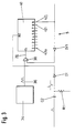
- the motor standstill detection circuit 5 shown in FIG. 3 has a differentiating circuit which is connected to the input RE of the counter and consists of the capacitor C1 and the resistor R1 connected to ground. With the capacitor C1 and the resistor R1, a diode D1 is connected in the forward direction to the reset input RE of a counter 40.
- the motor standstill detection circuit 5 has a signal generator 34, an AND logic component 38 and an inverter IV1. On the output side, the signal generator 34 is connected via a signal line 36 to an input of the AND logic component 38.
- the second input of the AND logic component 38 is connected to the output of the inverter IV1, which is connected on the input side to the most significant counter output 42j (9th bit).
- the AND logic component 38 is present at the counter input CL of the counter 40. If an input signal is present, a signal is present at the reset input RE of the counter 40, so that the counter 40 assumes a low level on the output side at the most significant counter output 42j. Only when there is no input signal, ie when the engine is at a standstill, is the counter 40 activated via the pulse sequence fed into the counter 40 by the signal generator 34 via the AND logic component 38 and assumes a high level on the output side.
- the counter output 42j is connected to the input of the control unit 2.
- control unit 2 the input signals are converted into individual control commands in cooperation with the control program to be called up from an electronic memory 6. These control commands are transmitted via data lines 8a-8h to the individual modules (see FIG. 1), namely injection valve modules 10 and 11, intake valve modules 12 and 13, exhaust valve modules 14 and 15 and ignition modules 16 and 17, each of which consists of individual electrical switches 10a, 11a, 12a, 13a, 14a, 15a, 16a and 17a and an injection valve 10b and 11b, or an inlet valve 12b and 13b, or an exhaust valve 14b and 15b or spark plugs 16b and 17b.
- injection valve modules 10 and 11 intake valve modules 12 and 13a, 14a, 15a, 16a and 17a
- ignition modules 16 and 17 each of which consists of individual electrical switches 10a, 11a, 12a, 13a, 14a, 15a, 16a and 17a and an injection valve 10b and 11b, or an inlet valve 12b and 13b, or an exhaust valve 14b and 15b or spark plugs 16b and 17b.
- control unit 2 In normal operation of the internal combustion engine, the control unit 2 is supplied with the electrical signals corresponding to the current crankshaft position by the absolute value angle transmitter 4 via the parallel-series converter 30. Simultaneously with this data indicating the absolute crankshaft position, the engine standstill detection circuit 5 supplies the control unit 2 with a signal which corresponds to a movement or the standstill of the crankshaft of the internal combustion engine. In addition to these controlled variables, seven further operating parameters of the internal combustion engine are transmitted to the control unit 2 via the data lines.
- control signals are generated in the control unit 2 which, via the data lines 8a-8h, the injection valve modules 10 and 11, the intake valve modules 12 and 13, the exhaust valve modules 14 and 15 and the ignition modules 16 and 17 are supplied.
- the switches 10a - 17a arranged in the modules 10 - 17 are switched by the control signals transmitted from the control unit 2 and control the injectors 10b and 11b or the intake valves 12b and 13b or the exhaust valves 14b and 15b and to the spark plugs electrical power supply igniters 16b and 17b directly.
Landscapes
- Engineering & Computer Science (AREA)
- Chemical & Material Sciences (AREA)
- Combustion & Propulsion (AREA)
- Mechanical Engineering (AREA)
- General Engineering & Computer Science (AREA)
- Theoretical Computer Science (AREA)
- Signal Processing (AREA)
- Combined Controls Of Internal Combustion Engines (AREA)
- Electrical Control Of Air Or Fuel Supplied To Internal-Combustion Engine (AREA)
Description
Die Erfindung betrifft eine Schaltungsanordnung zur elektronischen Steuerung einer Verbrennungskraftmaschine gemäß dem Oberbegriff des Patentanspruchs 1.The invention relates to a circuit arrangement for the electronic control of an internal combustion engine according to the preamble of
Die Verwendung elektronischer Bauteile, insbesondere zur Steuerung von Verbrennungskraftmaschinen z. B. in Kraftfahrzeugen ist bekannt. Derartige Bauelemente werden vorzugsweise eingesetzt, um im Zusammenwirken mit mechanischen Bauteilen den Funktionsablauf kostengünstig zu verbessern. So ist z. B. bei herkömmlichen Verbrennungskraftmaschinen das Zündverhalten (Zündzeitpunkt) mittels einer elektronisch aufbereiteten und von der Umdrehungszahl der Kraftmaschine abhängigen Kennlinie steuerbar.The use of electronic components, especially for controlling internal combustion engines such. B. in motor vehicles is known. Components of this type are preferably used in order to inexpensively improve the functional sequence in cooperation with mechanical components. So z. B. in conventional internal combustion engines, the ignition behavior (ignition timing) by means of an electronically processed and dependent on the number of revolutions of the engine characteristic.
Auch ist aus der DE 35 37 000 die Verwendung einer Codierscheibe, die mit einem Gray-Code versehen ist, und eines die Codierscheibe abtastenden Sensors zur statischen Erfassung der für die Zündauslösung ermittelten Lasterfassung bei einem Gleichdruckvergaser bekannt.Also known from DE 35 37 000 is the use of a coding disk which is provided with a Gray code and a sensor which scans the coding disk for the static detection of the load detection determined for the ignition triggering in a constant pressure carburetor.
Weiterhin sind aus der DE-OS 36 30 272 Vorrichtungen zum Steuern einer Brennkraftmaschine bekannt, bei denen die Position einer mit einer Welle der Brennkraftmaschine verbundenen Geberscheibe, die eine als Markierung ausgebildete Perforation aufweist, von einem raumfesten Aufnahmesegment registriert wird. Ein Nachteil dieser bekannten Steuervorrichtungen ist, daß diese nur die Steuerung einer einzigen Regelgröße (z. B. die Zündauslösung) ermöglichen.Furthermore, from DE-OS 36 30 272 devices for controlling an internal combustion engine are known, in which the position of a sensor disk connected to a shaft of the internal combustion engine and having a perforation designed as a marking is registered by a spatially fixed receiving segment. A disadvantage of these known control devices is that they only allow the control of a single controlled variable (e.g. the ignition trigger).
In der DE 36 09 070 A1 wird ein elektronisches Steuersystem für Verbrennungsmotoren beschrieben, bei welchem zwei durch Übertragungsleitungen miteinander verbundene Zentralrecheneinheiten eingangsseitig mit einzelnen den Motorzustand kennzeichnenden Größen versorgt werden. Neben den die Belastung des Motors angebenden Betriebsparametern werden einer Zentraleinheit Motorrotationsparameter zugeführt, die einer vorbestimmten Kurbelwinkellage entsprechen und welche von einer Abtasteinrichtung erfaßt werden. Dabei erzeugt ein Abtastsensor ein Bezugskurbelwinkelsignal, welches einer vorbestimmten festen Kurbelwinkellage eines einzelnen Motorzylinders entspricht, wodurch insbesondere lediglich relative Kurbelwinkelpositionen bestimmbar sind.DE 36 09 070 A1 describes an electronic control system for internal combustion engines in which two central processing units connected to one another by transmission lines are supplied on the input side with individual variables which characterize the engine state. In addition to the operating parameters specifying the load on the engine, a central unit is supplied with motor rotation parameters which correspond to a predetermined crank angle position and which are detected by a scanning device. A scanning sensor generates a reference crank angle signal which corresponds to a predetermined fixed crank angle position of an individual engine cylinder, whereby in particular only relative crank angle positions can be determined.
Aus US-A 4 742 811 ist eine Vorrichtung zur Zündzeitpunkt-Steuerung für Verbrennungsmaschinen bekannt. Der Kurbelwellenwinkel wird mit Hilfe eines mehrere magnetische Sektoren aufweisenden Zylinders mit Hilfe von Hall-Sonden bestimmt. Wesentlicher Nachteil hierbei ist, daß die Winkelposition im Stillstand nicht bestimmbar ist.From US-A 4 742 811 a device for ignition timing control for internal combustion engines is known. The crankshaft angle is determined with the aid of a cylinder having several magnetic sectors with the aid of Hall probes. The main disadvantage here is that the angular position cannot be determined at a standstill.
Der Erfindung liegt die Aufgabe zugrunde, eine elektronische Steuerung für Verbrennungskraftmaschinen zu schaffen, die die oben genannten Mängel vermeidet, eine hohe Betriebszuverlässigkeit aufweist und kostengünstig zu fertigen ist.The invention has for its object to provide an electronic control for internal combustion engines, which avoids the above-mentioned shortcomings, has a high operational reliability and is inexpensive to manufacture.
Diese Aufgabe wird erfindungsgemäß durch die im Patentanspruch 1 genannten kennzeichnenden Merkmale gelöst.This object is achieved by the characterizing features mentioned in
Weiterbildende vorteilhafte Merkmale sind in den Unteransprüchen angegeben.Advantageous features are specified in the subclaims.
Eine erfindungsgemäße Schaltungsanordnung für Verbrennungskraftmaschinen weist als wesentliche Komponenten eine elektronische Steuereinheit (Rechner), einen Absolutwertwinkelgeber, eine Motorstillstandserkennungsschaltung, eine Zündfolgeschaltung und eine Ventilsteuervorrichtung auf. Die Ansteuerung der elektrischen Funktionen der Zündfolgeschaltung und der Ventilsteuervorrichtung wird von der elektronischen Steuereinheit durchgeführt. Zur Ansteuerung der Steuereinheit werden dem Rechner von dem Absolutwertwinkelgeber, der den Kurbelwellenwinkel im dynamischen und statischen Zustand erfaßt, elektrische und mittels Signalformungsmodulen aufbereitete Signale zugeführt, die Regelgrößen darstellen. Weiterhin werden der Steuereinheit elektrische Signale von dem Absolutwertwinkelgeber und der Ventilsteuerung zugeführt, mittels derer der Winkelgebercode und die Ventilarbeitsfolge überwacht wird.A circuit arrangement according to the invention for internal combustion engines has as essential components an electronic control unit (computer), an absolute angle generator, an engine stop detection circuit, an ignition sequence circuit and a valve control device. The control of the electrical functions of the ignition sequence circuit and the valve control device is carried out by the electronic control unit. To control the control unit, the computer is supplied by the absolute value angle sensor, which detects the crankshaft angle in the dynamic and static state, with electrical signals which are processed by means of signal shaping modules and which represent controlled variables. Furthermore, the control unit is supplied with electrical signals from the absolute value angle encoder and the valve control, by means of which the angle encoder code and the valve work sequence are monitored.
Mit einer gemäß der Erfindung vorgeschlagenen voll-elektronischen Schaltungsvorrichtung zur Steuerung der Verbrennungskraftmaschine lassen sich folgenden Vorteile erzielen:
- 1. Verzicht auf eine elektrische Starthilfe (Anlasser),
- 2. Verzicht auf einen mechanisch angetriebenen Zündverteiler,
- 3. Verzicht auf eine die Einlaß- und Auslaßventile steuernde Nockenwelle und
- 4. neuartige Steuerung eines Zweitaktverbrennungsmotors, bei welchem vor allem die Kraftstoff-Luft-Gemisch-Zusammensetzung und die Phasenlage zwischen Kraftstoffeinspritzung und Kolbenposition in Abhängigkeit von den Betriebsdaten elektrisch steuerbar sind.
- 1. dispensing with an electrical starting aid (starter),
- 2. dispensing with a mechanically driven distributor,
- 3. No camshaft controlling the intake and exhaust valves and
- 4. Novel control of a two-stroke internal combustion engine, in which, in particular, the fuel-air mixture composition and the phase position between fuel injection and piston position are electrically controllable as a function of the operating data.
Der Absolutwertwinkelgeber besteht aus einem auf einer Kurbelwelle montierten Rad, das auf seiner Oberfläche einen eindeutig identifizierbaren Code trägt, der von einem Sensor abgetastet wird. Die Abtastung durch den Sensor erfolgt z. B. induktiv oder optisch. Vorzugsweise wird für die Codierscheibe (Rad) ein einschrittiger 9-Bit-Gray-Code, der eine auf 0,7° genaue Bestimmung der Kurbelwellenwinkelposition ermöglicht, verwendet. Die Codemuster der einzelnen Spuren der Codierscheibe werden mittels eines Multifunktionssensors mit integrierter Elektronik simultan abgetastet und in elektrische Signale, die zur weiteren Verarbeitung aufbereitet werden, umgesetzt. Diese elektronisch aufbereiteten Signale werden über eine parallel serielle Schnittstelle (Parallelserienwandler) der Steuereinheit sequentiell zugeführt.The absolute angle encoder consists of one on one Crankshaft-mounted wheel that carries a clearly identifiable code on its surface, which is scanned by a sensor. The scanning by the sensor takes place, for. B. inductive or optical. A one-step 9-bit Gray code, which enables the crankshaft angle position to be determined with an accuracy of 0.7 °, is preferably used for the coding disk (wheel). The code patterns of the individual tracks of the coding disk are scanned simultaneously by means of a multifunction sensor with integrated electronics and converted into electrical signals that are processed for further processing. These electronically processed signals are sequentially fed to the control unit via a parallel serial interface (parallel series converter).
Mit dem Eingang des niederwertigsten Bits des Parallelserienwandlers ist der Eingang der Motorstillstandserkennungsschaltung verbunden. In der Eingangsstufe der Motorstillstandserkennungsschaltung wird das Eingangssignal elektronisch differenziert und einem Zähler zugeführt, der bei Fehlen eines eingangsseitigen Signals ausgangsseitig ein dem Motorzustand (Stillstand oder Betrieb) entsprechendes Signal erzeugt, welches der Steuereinheit zugeführt wird. Die simultane elektronische Auswertung sämtlicher (9 Bit) Codespuren und einer einzigen Codespur, nämlich der niederwertigsten (1. Bit), ist somit vorteilhaft durch eine schnellarbeitende Motorstillstandserkennungsschaltung und in Ergänzung dazu mittels einer hoch auflösenden Kurbelwellenwinkelpositionsbestimmung in der Steuereinheit möglich.The input of the motor standstill detection circuit is connected to the input of the least significant bit of the parallel series converter. In the input stage of the motor standstill detection circuit, the input signal is electronically differentiated and fed to a counter which, in the absence of a signal on the input side, generates a signal corresponding to the motor state (standstill or operation) on the output side, which signal is fed to the control unit. The simultaneous electronic evaluation of all (9 bit) code tracks and a single code track, namely the least significant (1st bit), is thus advantageously possible by means of a fast-working engine standstill detection circuit and, in addition, by means of a high-resolution determination of the crankshaft angle in the control unit.
Aus den der Steuereinheit von der Motorstillstandserkennungsschaltung und dem Absolutwertwinkelgeber zugeführten elektrischen Signalen werden von der Steuereinheit einzelne jeweils einem Zylinder zugeordnete Einspritzventile, Einlaßventile, Auslaßventile und Zündkerzen angesteuert, die jeweils aus einem elektrischen Schalter und einem z. B. elektromagnetisch betriebenen Ventil bzw. einer Zündvorrichtung und einer Zündkerze bestehen, im folgenden Einspritzventilmodul, Einlaßventilmodul, Auslaßventilmodul und Zündmodul genannt. Die Reihenfolge der sequentiellen Ansteuerung der einzelnen Module erfolgt in Abhängigkeit der Gesamtzylinderzahl der Verbrennungskraftmaschine und der Zylinderarbeitszyklen. Gemäß einer Unterteilung der Zylinderarbeitszyklen in eine Zünd-, Zylinderschließ- und Zylinderöffnungsfolge wird eine Kurbelwellenumdrehung mit der halben Zylinderzahl gleichmäßig aufgeteilt, z. B. für eine sechszylindrige Verbrennungskraftmaschine in drei Sektoren à 120°. Als Ersatz für die Nockenwellensignalfunktion werden mittels einer Flip-Flop-Schaltung die Sektoren nach einer Kurbelwellenumdrehung auf die jeweils andere Zylindergruppe umgeschaltet. So erfolgt bei der ersten Umdrehung die Zündung in den Zylindern 1, 2 und 3 und während der zweiten Umdrehung in den Zylindern 4, 5 und 6. Analog dieser Zündreihenfolge erfolgt die Ventilansteuerung. Vorteilhaft ist, daß bei einer derartigen Unterteilung in drei 120°-Sektoren der Zündzeitpunkt und auch die Zünddauer den momentanen Motorbedürfnissen präzise anpaßbar sind.The control unit uses the electrical signals supplied to the control unit by the engine standstill detection circuit and the absolute value angle transmitter to inject individual injection valves, intake valves, Exhaust valves and spark plugs controlled, each consisting of an electrical switch and a z. B. electromagnetically operated valve or an ignition device and a spark plug, called in the following injection valve module, intake valve module, exhaust valve module and ignition module. The sequence of the sequential activation of the individual modules depends on the total number of cylinders of the internal combustion engine and the cylinder work cycles. According to a subdivision of the cylinder working cycles into an ignition, cylinder closing and cylinder opening sequence, a crankshaft revolution with half the number of cylinders is divided equally, e.g. B. for a six-cylinder internal combustion engine in three sectors of 120 °. As a replacement for the camshaft signal function, the sectors are switched over to the other cylinder group after a crankshaft revolution by means of a flip-flop circuit. Thus, the ignition takes place in
Ebenfalls sind die einzelnen Ventilsteuermodule jeweils entsprechend dem aktuellen Motorzustand ansteuerbar. So können während des Motorlaufs jederzeit eine Optimierung der Ventilschließ- und Ventilöffnungszeiten sowie deren Phasenlage zueinander eingestellt werden. Wegen der absoluten, d. h. statischen, Kurbelwellenwinkelerfassung kann für den Start einer derartig elektronisch gesteuerten Verbrennungskraftmaschine auf eine elektrisch angetriebene Starthilfe (Anlasser) gänzlich verzichtet werden. Während der Start- und Hochlaufphase läßt sich folgender Funktionsablauf realisieren:
- Einschalten der Betriebsspannung (z. B. mit dem Zündschalter),
- Aufbau eines Überdrucks (ca. 3 atm) im Ansaugkanal mittels eines der Drosselklappe vorgeschalteten Kompressors,
- kurzzeitiges Öffnen aller Ein- und Auslaßventile zur Spülung,
- sequentielles Öffnen der Einlaßventile für diejenigen Zylinder, deren Kolbenposition sich unmittelbar nach dem oberen Totpunkt (vor dem unteren Totpunkt) sowie derjenigen Zylinder, deren Kolbenposition sich unmittelbar vor dem oberen Totpunkt befindet, um Luft einzulassen,
- Schließen der Einlaßventile,
- Kraftstoffdirekteinspritzung (Ansteuerung der Einspritzventile) für die zu zündenden Zylinder, wobei die Einspritzventile von der Steuereinheit derart angesteuert werden, daß sich ein Wert für λ= 1 ergibt,
- Zündung der Zylinder, deren Kolbenposition sich unmittelbar nach dem oberen Totpunkt aber vor dem unteren Totpunkt befindet, wobei die Zünddauer bis zur Bewegung der Kolben in den unteren Totpunkt eingeschaltet bleibt,
- anschließende Zündung der Kolben, die nun den oberen Totpunkt überschritten haben, wobei die Zünddauer sich bis zur Abwärtsbewegung des Kolbens in den unteren Totpunkt erstreckt und
- Übergang (Hochlauf) in den Normalbetrieb.
- Switch on the operating voltage (e.g. with the ignition switch),
- Development of an overpressure (approx. 3 atm) in the intake duct by means of a compressor upstream of the throttle valve,
- brief opening of all inlet and outlet valves for flushing,
- sequential opening of the intake valves for those cylinders whose piston position is immediately after top dead center (before bottom dead center) and those cylinders whose piston position is immediately before top dead center to let in air,
- Closing the inlet valves,
- Direct fuel injection (control of the injection valves) for the cylinders to be ignited, the injection valves being controlled by the control unit in such a way that a value for λ = 1 results,
- Ignition of the cylinders whose piston position is immediately after top dead center but before bottom dead center, the ignition duration remaining on until the pistons move to bottom dead center,
- subsequent ignition of the pistons, which have now passed top dead center, the duration of ignition extending until the piston moves down to bottom dead center and
- Transition (run-up) to normal operation.
Erst im Normalbetrieb wird die Drosselklappenposition und die Ventilmodulansteuerung von der Steuereinheit in Abhängigkeit des Ausgangssignals der Motorstillstandserkennungsschaltung von Start- auf Normalbetrieb umgeschaltet.Only in normal operation is the throttle valve position and the valve module control switched over from the control unit depending on the output signal of the engine standstill detection circuit from start to normal operation.
Vorteilhaft sind die elektrisch angesteuerten Einlaß-, Auslaß- und Einspritzventile auch beim Motorstart sequentiell ansteuerbar, wodurch die elektrische Leistungsaufnahme reduziert wird.The electrically controlled inlet, Exhaust and injection valves can also be controlled sequentially when the engine is started, which reduces electrical power consumption.
Auch läßt sich durch den Vorschlag der unter Verzicht auf eine Nockenwelle nicht miteinander mechanisch gekoppelten Ein-, Auslaß- und der Einspritzventile sowie der Zündmodule ein Zweitaktbetrieb unter Meidung der bekannten Nachteile realisieren. Der Wechsel der Zylinderladung, d. h. die Spülung, erfolgt durch gleich- und kurzzeitiges Öffnen der Ein- und Auslaßventile, wodurch eine Zwangsspülung mit Luft erfolgt. Im Anschluß daran wird Kraftstoff mittels der Einspritzventile in den Zylinder gespritzt. Dabei bestimmt der Einlaßdruck die Phasenlage zur Spülung der Kolbenposition. Durch Variation des Kraftstoffeinlaßdruckes kann der Einlaßdruck so groß gewählt werden, daß er dem Zylinderinnendruck im oberen Totpunkt entspricht, wodurch auf eine Zwangsspülung verzichtet werden kann. In diesem Fall erfolgt der Abgasausstoß nahezu während des gesamten zweiten Taktes, wohingegen die Beschickung des Zylinders mit Kraftstoff erst vor dem oberen Totpunkt erfolgt. Dadurch ist eine flexible Anpassung an die speziellen Motorbedürfnisse wie Motordrehmoment, Motorleistung, Kraftstoffparameter und Gemischzusammensetzung möglich.The proposal of the intake, exhaust and injection valves and the ignition modules, which are not mechanically coupled to one another without a camshaft, enables two-stroke operation to be avoided while avoiding the known disadvantages. The change in cylinder charge, i. H. the flushing takes place by simultaneously and briefly opening the inlet and outlet valves, which results in a forced flushing with air. Subsequently, fuel is injected into the cylinder using the injection valves. The inlet pressure determines the phase position for flushing the piston position. By varying the fuel inlet pressure, the inlet pressure can be chosen so high that it corresponds to the cylinder internal pressure at top dead center, which means that forced purging can be dispensed with. In this case, the exhaust gas is emitted almost during the entire second cycle, whereas the cylinder is only supplied with fuel before top dead center. This enables flexible adaptation to the special engine requirements such as engine torque, engine power, fuel parameters and mixture composition.
Im folgenden wird die Erfindung anhand eines bevorzugten und in Zeichnungen dargestellten Ausführungsbeispiels näher erläutert. Es zeigen:
Figur 1- Blockschaltbild einer erfindungsgemäßen elektronischen Steuerung für Verbrennungskraftmaschinen,
Figur 2- Blockschaltbild des 9-Bit-Absolutwertwinkelgebers und
Figur 3- Blockschaltbild der Schaltung zur Motorstillstandserkennung gemäß der Erfindung.
- Figure 1
- Block diagram of an electronic control according to the invention for internal combustion engines,
- Figure 2
- Block diagram of the 9-bit absolute encoder and
- Figure 3
- Block diagram of the circuit for engine standstill detection according to the invention.
Die Schaltung zur elektronischen Steuerung der Verbrennungskraftmaschine umfaßt eine zentrale Steuereinheit 2, einen Absolutwertwinkelgeber 4, einen elektronischen Steuerprogrammspeicher 6, eine in Fig. 3 dargestellte Motorstillstandserkennungsschaltung 5 sowie entsprechend der Anzahl der anzusteuernden Motorzylinder Einspritzventilmodule 10, 11, Einlaßventilmodule 12, 13, Auslaßventilmodule 14, 15 und Zündmodule 16, 17.The circuit for the electronic control of the internal combustion engine comprises a
Die Steuerung sämtlicher Module 10 bis 17 erfolgt durch die Steuereinheit 2 in Abhängigkeit der momentanen Betriebsparameter der Verbrennungskraftmaschine, die der Steuereinheit 2 von dem Absolutwertwinkelgeber 4 und zusätzlichen, die Betriebsparameter der Verbrennungskraftmaschine messenden Sensoren über Datenleitungen 7 zugeführt werden.All of the
Der Absolutwertwinkelgeber 4 besteht aus insgesamt neun Signalformungsmodulen, von denen in Fig. 2 nur zwei 20a, 20b dargestellt sind. Die Signalformungsmodule 20a, 20b weisen jeweils einen Parallelschwingkreis, bestehend aus einer Induktivität La bzw. Lb und einem Kondensator Ca bzw. Cb, einen Oszillator 22a bzw. 22b sowie einen seriell zum Parallelschwingkreis geschalteten Demodulator 24a bzw. 24b auf, wobei jeweils der Ausgang des Demodulators 24a bzw. 24b mit dem invertierenden Eingang eines Komparators 26a bzw. 26b verbunden ist. In Zusammenwirken mit einer am nicht invertierenden Eingang des Komparators 26a bzw. 26b anliegenden Referenzspannung URA bzw. URB erzeugt der Komparator 26a bzw. 26b ein Ausgangssignal, das über eine Datenleitung 28a bzw. 28b dem Paralleleingang eines Parallel-Serien-Wandlers 30 zugeführt wird. Die parallel zugeführten Winkelpositionsdaten des Absolutwertwinkelgebers 4 werden über eine Datenleitung 32, die den Parallel-Serien-Wandler 30 ausgangsseitig mit der Steuereinheit 2 eingangsseitig verbindet, sequentiell übertragen.The absolute
Mit dem niederwertigsten Paralleleingang (1. Bit) des Parallel-Serien-Wandlers 30 ist der Eingang der Motorstillstandserkennungsschaltung 5 verbunden. Die in Figur 3 dargestellte Motorstillstandserkennungsschaltung 5 weist eine mit dem Eingang RE des Zählers verbundene Differenzierschaltung auf, die aus dem Kondensator C1 und dem mit Masse verbundenen Widerstand R1 besteht. Mit dem Kondensator C1 und dem Widerstand R1 ist eine Diode D1 in Durchgangsrichtung mit dem Rücksetzeingang RE eines Zählers 40 verbunden. Weiterhin weist die Motorstillstandserkennungsschaltung 5 einen Signalgenerator 34, ein UND-Logikbauteil 38 und einen Inverter IV1 auf. Ausgangsseitig ist der Signalgenerator 34 über eine Signalleitung 36 mit einem Eingang des UND-Logikbauteils 38 verbunden. Der zweite Eingang des UND-Logikbauteils 38 ist mit dem Ausgang des Inverters IV1, der eingangsseitig an dem höchstwertigen Zählerausgang 42j (9. Bit) liegt, verbunden. Ausgangsseitig liegt das UND-Logikbauteil 38 am Zählereingang CL des Zählers 40 an. Bei Vorhandensein eines Eingangssignals liegt am Rücksetzeingang RE des Zählers 40 ein Signal an, so daß der Zähler 40 ausgangsseitig am höchstwertigen Zählerausgang 42j ein Low-Pegel annimmt. Erst bei Fehlen eines Eingangssignals, d. h. bei Motorstillstand, wird über die vom Signalgenerator 34 über das UND-Logikbauteil 38 in den Zähler 40 eingespeiste Pulsfolge der Zähler 40 aktiv und nimmt ausgangsseitig einen High-Pegel an. Der Zählerausgang 42j ist mit dem Eingang der Steuereinheit 2 verbunden.The input of the motor
In der Steuereinheit 2 werden die Eingangssignale in Zusammenwirken mit aus einem elektronischen Speicher 6 abzurufenden Steuerprogramm in einzelne Steuerbefehle umgesetzt. Diese Steuerbefehle werden über Datenleitungen 8a - 8h den einzelnen Modulen (s. Fig. 1), nämlich Einspritzventilmodulen 10 und 11, Einlaßventilmodulen 12 und 13, Auslaßventilmodulen 14 und 15 sowie Zündmodulen 16 und 17, die jeweils aus einzelnen elektrischen Schaltern 10a, 11a, 12a, 13a, 14a, 15a, 16a bzw. 17a und einem Einspritzventil 10b und 11b, bzw. einem Einlaßventil 12b und 13b, bzw. einem Auslaßventil 14b und 15b bzw. Zündkerzen 16b und 17b bestehen, zugeführt.In the
Im Normalbetrieb der Verbrennungskraftmaschine werden der Steuereinheit 2 von dem Absolutwertwinkelgeber 4 über den Parallel-Serien-Wandler 30 die der momentanen Kurbelwellenposition entsprechenden elektrischen Signale zugeleitet. Simultan zu diesen die absolute Kurbelwellenposition angebenden Daten wird durch die Motorstillstandserkennungsschaltung 5 der Steuereinheit 2 ein Signal zugeführt, das einer Bewegung oder dem Stillstand der Kurbelwelle der Verbrennungskraftmaschine entspricht. In Ergänzung zu diesen Regelgrößen werden der Steuereinheit 2 über die Datenleitungen sieben weitere Betriebsparameter der Verbrennungskraftmaschine übermittelt.In normal operation of the internal combustion engine, the
In Zusammenwirken mit den aus dem elektronischen Speicher 6 in die Steuereinheit 2 zu übertragenden Steuerprogrammteilen und den aktuellen Betriebsparametern (Regelgrößen) werden in der Steuereinheit 2 Steuersignale erzeugt, die über die Datenleitungen 8a - 8h den Einspritzventilmodulen 10 und 11, den Einlaßventilmodulen 12 und 13, den Auslaßventilmodulen 14 und 15 sowie den Zündmodulen 16 und 17 zugeleitet werden.In cooperation with the control program parts to be transferred from the
Die in den Modulen 10 - 17 angeordneten Schalter 10a - 17a werden durch die aus der Steuereinheit 2 übermittelten Steuersignale geschaltet und steuern jeweils die Einspritzventile 10b und 11b bzw. die Einlaßventile 12b und 13b bzw. die Auslaßventile 14b und 15b und die an die Zündkerzen mit elektrischer Energie versorgenden Zündvorrichtungen 16b und 17b direkt an.The switches 10a - 17a arranged in the modules 10 - 17 are switched by the control signals transmitted from the
Claims (11)
- A switching arrangement for the electronic control of an internal combustion engine having an electronic control module (2) and an electronic memory (6) for the storage of control programmes to be transmitted from the control module (2) and having injection valves (16, 11) which can be triggered electrically by the control module (2) as a function of operating parameters, in particular the crankshaft position, the engine speed, the exhaust gas composition and the engine torque,
characterised by an engine stoppage identification circuit (5) and an absolute value angle transmitter (4) having a code disc, which is securely connected to the crankshaft of the internal combustion engine and which possesses a preferably single-step code, which can be automatically checked for errors by the control module (2), for the generation of signals corresponding to the crankshaft position during stoppage and during rotation, and also electrical signals corresponding to the engine temperature, engine load and the engine pinking, which are supplied as operating parameters to the electric control module (2), whereby the inlet valves (12, 13), the outlet valves (14, 15) and the injection valves (10, 11) and also the ignition device (16, 17) can be electrically controlled by the control module (2) as a function of the operating parameters, whereby the control module (2) possesses a run-up programme, with which the ignition sequence of the engine cylinders, the inlet valves (12, 13), the injection valves (10, 11) and the ignition device (16, 17) can be electrically triggered for any cylinder position of the engine start-up.
- A switching arrangement according to Claim 1,
characterised in that the code is a 9-bit Gray code. - A switching arrangement according to Claim 1 and/or 2,
characterised in that the code disc is divided into a number of sectors corresponding to half the number of cylinders. - A switching arrangement according to one of Claims 1 to 3,
characterised in that the sectors can be switched to another cylinder group by means of a flip-flop circuit. - A switching arrangement according to at least one of Claims 1 to 4,
characterised in that the absolute value angle transmitter (4) comprises at least one signal forming module (20a, 20b) associated with a code track. - A switching arrangement according to one of Claims 1 to 5,
characterised in that each signal forming module (20a, 20b) comprises a parallel resonant circuit consisting of a capacitor (Ca or CB), an inductive resistor (La or Lb) and an oscillator (22a or 22b); a demodulator (24a or 24b) connected in series to the parallel resonant circuit and a comparator (26a or 26b), the inverting input of which is connected to the output of the demodulator (24a or 24b) and the non-inverting input of which a reference voltage (URA, URB) abuts and the output of which is connected to at least one parallel input of a parallel-series converter (30). - A switching arrangement according to at least one of Claims 1 to 6,
characterised in that the control module (2) is connected to a sensor for the identification of engine rotation, whereby preferably the lowest value bit of the parallel input of the parallel-series converter (30) is preferably connected to the input of the engine stoppage identification circuit. - A switching arrangement according to at least one of Claims 1 to 7,
characterised in that the engine stoppage identification circuit (5) consists of a signal generator (34), a counter (40), an AND component (38), an inverter (IV) and a differential element, disposed at the input side, having a capacitor (C2) and a resistor (R1), which supplies the differentiating input signal via a diode (D1) to the reset input (RE) of the counter (40), while the output of the signal generator (34) is connected to the first input of the AND logical unit (38), and at least one output, preferably the highest-value output (42j), is connected to the second input of the AND logical unit (38), and the output of the AND logical unit (38) is connected to the counter input (CL) of the counter (40). - A switching arrangement according to at least one of Claims 1 to 8,
characterised in that the inlet, outlet and injection valves (10b, 11b, 12b, 13b, 14b, 15b) can be sequentially triggered during engine start-up. - A switching arrangement according to at least one of Claims 1 to 9,
characterised in that the inlet valves (12b, 13b), the outlet valves (14b, 15b) and the injection valves (10b, 11b) can be triggered by the control module (2) so that the engine is operated in two-stroke operating mode. - A switching arrangement according to Claim 10, characterised in that the number of angular sectors of a camshaft rotation is equal to the number of cylinders.
Applications Claiming Priority (2)
| Application Number | Priority Date | Filing Date | Title |
|---|---|---|---|
| DE4039062A DE4039062C1 (en) | 1990-12-07 | 1990-12-07 | |
| DE4039062 | 1990-12-07 |
Publications (3)
| Publication Number | Publication Date |
|---|---|
| EP0490088A2 EP0490088A2 (en) | 1992-06-17 |
| EP0490088A3 EP0490088A3 (en) | 1992-09-02 |
| EP0490088B1 true EP0490088B1 (en) | 1994-03-02 |
Family
ID=6419799
Family Applications (1)
| Application Number | Title | Priority Date | Filing Date |
|---|---|---|---|
| EP91119124A Expired - Lifetime EP0490088B1 (en) | 1990-12-07 | 1991-11-11 | Circuit for the electronic control of an internal combustion engine |
Country Status (4)
| Country | Link |
|---|---|
| US (1) | US5199394A (en) |
| EP (1) | EP0490088B1 (en) |
| DE (2) | DE4039062C1 (en) |
| WO (1) | WO1992011452A2 (en) |
Families Citing this family (30)
| Publication number | Priority date | Publication date | Assignee | Title |
|---|---|---|---|---|
| DE4230616A1 (en) * | 1992-09-12 | 1994-03-17 | Bosch Gmbh Robert | Device for recognizing the position of at least one shaft having a reference mark |
| DE4243259A1 (en) * | 1992-12-19 | 1994-06-23 | Kloeckner Humboldt Deutz Ag | Self-correcting timing control for vehicle ignition |
| JP2767352B2 (en) * | 1993-02-02 | 1998-06-18 | 株式会社ユニシアジェックス | Air-fuel ratio control device for starting internal combustion engine |
| DE4304163A1 (en) * | 1993-02-12 | 1994-08-25 | Bosch Gmbh Robert | Device for controlling fuel injection in an internal combustion engine |
| US5479909A (en) * | 1993-05-12 | 1996-01-02 | Polaris Industries L.P. | Snowmobile with control system for activating electronic fuel injection |
| US5622053A (en) * | 1994-09-30 | 1997-04-22 | Cooper Cameron Corporation | Turbocharged natural gas engine control system |
| US5596956A (en) * | 1994-12-16 | 1997-01-28 | Honda Giken Kogyo Kabushiki Kaisha | Electromagnetically driven valve control system for internal combustion engines |
| JP3791938B2 (en) * | 1994-12-27 | 2006-06-28 | ヤマハマリン株式会社 | Engine ignition timing control device |
| DE19503270C2 (en) * | 1995-02-02 | 2003-11-06 | Bosch Gmbh Robert | Method for determining a vehicle standstill time |
| AUPN561095A0 (en) * | 1995-09-25 | 1995-10-19 | Orbital Engine Company (Australia) Proprietary Limited | Engine control strategy |
| DE19716916A1 (en) * | 1997-04-23 | 1998-10-29 | Porsche Ag | ULEV concept for high-performance engines |
| US5740771A (en) * | 1997-05-09 | 1998-04-21 | Sebastian; Duane J. | Computer controlled intake and exhaust valve |
| DE19732903A1 (en) | 1997-07-30 | 1999-02-04 | Falk Pharma Gmbh | Pellet formulation for the treatment of the intestinal tract |
| JP2001010360A (en) | 1999-06-28 | 2001-01-16 | Suzuki Motor Corp | Hybrid power vehicle |
| DE10020325A1 (en) * | 2000-04-26 | 2001-11-08 | Bosch Gmbh Robert | Method for starting a multi-cylinder internal combustion engine |
| US6418003B1 (en) | 2000-07-05 | 2002-07-09 | Ford Global Technologies, Inc. | Control methods for electromagnetic valve actuators |
| DE10039948A1 (en) * | 2000-08-16 | 2002-02-28 | Siemens Ag | Starting internal combustion engine involves igniting fuel-air mixture in selected cylinder(s) with piston(s) just beyond TDC following sequence of flushing with air and fuel introduction |
| JP4742433B2 (en) * | 2000-09-29 | 2011-08-10 | マツダ株式会社 | Engine control device |
| DE10228147B3 (en) * | 2002-06-24 | 2004-01-22 | Siemens Ag | Method for determining the starting angular position of an internal combustion engine |
| US6868832B2 (en) * | 2003-07-09 | 2005-03-22 | Honda Motor Co., Ltd. | Electronic controlled fuel injection apparatus of internal combustion engine |
| US7051693B2 (en) * | 2003-11-21 | 2006-05-30 | Mazda Motor Corporation | Engine starting system |
| US7092814B1 (en) * | 2004-09-16 | 2006-08-15 | Yazaki North America, Inc. | Sequential engine function control system |
| JP2006299997A (en) * | 2005-04-22 | 2006-11-02 | Toyota Motor Corp | Internal combustion engine starting device |
| DE102005027654A1 (en) * | 2005-06-15 | 2006-12-21 | Robert Bosch Gmbh | Sensor for position detection when starting an internal combustion engine |
| DE102007023553B3 (en) * | 2007-05-21 | 2008-12-04 | Continental Automotive Gmbh | Device and method for controlling a drive unit |
| JP5359628B2 (en) * | 2009-07-13 | 2013-12-04 | 株式会社デンソー | Energization control system |
| EP3101765B1 (en) | 2010-06-28 | 2018-02-14 | Maxwell Technologies, Inc. | Maximizing life of capacitors in series modules |
| WO2013074544A2 (en) | 2011-11-15 | 2013-05-23 | Maxwell Technologies, Inc. | System and methods for managing a degraded state of a capacitor system |
| US11131567B2 (en) | 2019-02-08 | 2021-09-28 | Honda Motor Co., Ltd. | Systems and methods for error detection in crankshaft tooth encoding |
| US11959820B2 (en) | 2021-03-17 | 2024-04-16 | Honda Motor Co., Ltd. | Pulser plate balancing |
Family Cites Families (14)
| Publication number | Priority date | Publication date | Assignee | Title |
|---|---|---|---|---|
| US3757755A (en) * | 1971-10-14 | 1973-09-11 | Inst Gas Technology | Engine control apparatus |
| DE2343905C2 (en) * | 1973-08-31 | 1982-10-07 | Daimler-Benz Ag, 7000 Stuttgart | Device for digital-electronic control of the inlet, outlet and injection valves as well as the ignition in internal combustion engines |
| DE3117144A1 (en) * | 1981-04-30 | 1982-11-18 | Fa. Emil Bender, 5900 Siegen | Starter device for a multi-cylinder spark-ignition engine |
| JPS5851070U (en) * | 1981-10-01 | 1983-04-06 | 三菱電機株式会社 | internal combustion engine ignition system |
| JPS5980186A (en) * | 1982-10-26 | 1984-05-09 | Fanuc Ltd | Rotor position detecting circuit for motor |
| US4791569A (en) * | 1985-03-18 | 1988-12-13 | Honda Giken Kogyo Kabushiki Kaisha | Electronic control system for internal combustion engines |
| DE3537000A1 (en) * | 1985-10-17 | 1987-04-23 | Bosch Gmbh Robert | Carburettor for preparation of the fuel-air mixture for an internal combustion engine |
| DE3541624A1 (en) * | 1985-11-25 | 1987-05-27 | Siemens Ag | ARRANGEMENT FOR IDENTIFYING ANGLE IMPULSES |
| DE3630272A1 (en) * | 1986-09-05 | 1988-03-17 | Bosch Gmbh Robert | DEVICE FOR CONTROLLING AN INTERNAL COMBUSTION ENGINE |
| JPS63106362A (en) * | 1986-10-23 | 1988-05-11 | Honda Motor Co Ltd | Ignition control device for internal combustion engine |
| DE3707190A1 (en) * | 1987-03-06 | 1988-09-22 | Pav Praezisions Apparatebau Ag | MEASURING CLAMP |
| JPS63242028A (en) * | 1987-03-30 | 1988-10-07 | Ishikawajima Harima Heavy Ind Co Ltd | Multi-rotation absolute address type position detector |
| JPH01153910A (en) * | 1987-12-10 | 1989-06-16 | Omron Tateisi Electron Co | Speed and angle controller |
| US5101780A (en) * | 1991-04-02 | 1992-04-07 | Globe-Union Inc. | Reduced starting load system for an automobile engine |
-
1990
- 1990-12-07 DE DE4039062A patent/DE4039062C1/de not_active Expired - Fee Related
-
1991
- 1991-11-11 DE DE91119124T patent/DE59101099D1/en not_active Expired - Fee Related
- 1991-11-11 EP EP91119124A patent/EP0490088B1/en not_active Expired - Lifetime
- 1991-11-15 US US07/793,028 patent/US5199394A/en not_active Expired - Fee Related
- 1991-12-09 WO PCT/DE1991/000955 patent/WO1992011452A2/en active Search and Examination
Also Published As
| Publication number | Publication date |
|---|---|
| DE59101099D1 (en) | 1994-04-07 |
| EP0490088A3 (en) | 1992-09-02 |
| DE4039062C1 (en) | 1992-06-04 |
| WO1992011452A2 (en) | 1992-07-09 |
| EP0490088A2 (en) | 1992-06-17 |
| US5199394A (en) | 1993-04-06 |
| WO1992011452A3 (en) | 1992-08-06 |
Similar Documents
| Publication | Publication Date | Title |
|---|---|---|
| EP0490088B1 (en) | Circuit for the electronic control of an internal combustion engine | |
| EP0612373B1 (en) | Device for identifying the position of at least one shaft having a reference mark | |
| EP0643803B1 (en) | Sensor arrangement for rapid cylinder identification in a multi-cylinder internal combustion engine | |
| EP0262166B1 (en) | Process for identifying the working cycle of a cylinder in an internal combustion engine | |
| DE4141713C2 (en) | Encoder arrangement for cylinder detection and emergency operation in an internal combustion engine with n cylinders | |
| WO1998012432A1 (en) | Methods to determine the phase angle of a four stroke internal combustion engine with an odd number of cylinders | |
| DE19521277A1 (en) | Device for cylinder detection in a multi-cylinder internal combustion engine | |
| EP1114324B1 (en) | Device for detecting the reverse rotation of a rotating part of an internal combustion engine | |
| EP0683855A1 (en) | Fuel injection control device for an internal combustion engine. | |
| EP1590563B1 (en) | Method for controlling a direct injection of an internal combustion engine | |
| EP0739448B1 (en) | Process for monitoring the running of an internal combustion engine to detect misfiring | |
| DE19638338A1 (en) | Encoder arrangement for quick cylinder recognition in an internal combustion engine | |
| EP1070964A2 (en) | Device for the detection of the reverse rotation of a rotary part of an internal combustion engine | |
| DE4143094C2 (en) | Method and arrangement for electronic control of fuel injectors for an internal combustion engine | |
| DE19810214B4 (en) | Method for synchronizing a multi-cylinder internal combustion engine | |
| DE10310365B4 (en) | Control device for an internal combustion engine | |
| DE4418579B4 (en) | Device for regulating an internal combustion engine | |
| WO2003060307A1 (en) | Method and device for identifying a phase of a four-stroke spark ignition engine | |
| EP0325587B1 (en) | Ignition and injection system for internal combustion engines | |
| EP0544682B1 (en) | Ignition system for internal-combustion engines | |
| DE4040828A1 (en) | CONTROL SYSTEM FOR A FUEL PUMP | |
| DE10255622B4 (en) | A method of providing engine timing information for a multi-cylinder engine and internal combustion engine | |
| DE4418578B4 (en) | Device for detecting the phase position in an internal combustion engine | |
| DE4007395A1 (en) | IC engine ignition timing control - uses rotation sensor to detect actual ignition timing compared with calculated ignition timing | |
| DE69532493T2 (en) | Synchronization device without a camshaft position sensor for an internal combustion engine |
Legal Events
| Date | Code | Title | Description |
|---|---|---|---|
| PUAI | Public reference made under article 153(3) epc to a published international application that has entered the european phase |
Free format text: ORIGINAL CODE: 0009012 |
|
| AK | Designated contracting states |
Kind code of ref document: A2 Designated state(s): DE FR GB IT SE |
|
| PUAL | Search report despatched |
Free format text: ORIGINAL CODE: 0009013 |
|
| AK | Designated contracting states |
Kind code of ref document: A3 Designated state(s): DE FR GB IT SE |
|
| 17P | Request for examination filed |
Effective date: 19920821 |
|
| 17Q | First examination report despatched |
Effective date: 19930122 |
|
| ITF | It: translation for a ep patent filed |
Owner name: FIAMMENGHI FIAMMENGHI RACHELI |
|
| GRAA | (expected) grant |
Free format text: ORIGINAL CODE: 0009210 |
|
| AK | Designated contracting states |
Kind code of ref document: B1 Designated state(s): DE FR GB IT SE |
|
| ET | Fr: translation filed | ||
| REF | Corresponds to: |
Ref document number: 59101099 Country of ref document: DE Date of ref document: 19940407 |
|
| GBT | Gb: translation of ep patent filed (gb section 77(6)(a)/1977) |
Effective date: 19940324 |
|
| ITTA | It: last paid annual fee | ||
| PLBE | No opposition filed within time limit |
Free format text: ORIGINAL CODE: 0009261 |
|
| STAA | Information on the status of an ep patent application or granted ep patent |
Free format text: STATUS: NO OPPOSITION FILED WITHIN TIME LIMIT |
|
| EAL | Se: european patent in force in sweden |
Ref document number: 91119124.5 |
|
| 26N | No opposition filed | ||
| REG | Reference to a national code |
Ref country code: GB Ref legal event code: IF02 |
|
| PGFP | Annual fee paid to national office [announced via postgrant information from national office to epo] |
Ref country code: GB Payment date: 20021106 Year of fee payment: 12 |
|
| PGFP | Annual fee paid to national office [announced via postgrant information from national office to epo] |
Ref country code: FR Payment date: 20021118 Year of fee payment: 12 |
|
| PGFP | Annual fee paid to national office [announced via postgrant information from national office to epo] |
Ref country code: SE Payment date: 20021128 Year of fee payment: 12 |
|
| PG25 | Lapsed in a contracting state [announced via postgrant information from national office to epo] |
Ref country code: GB Free format text: LAPSE BECAUSE OF NON-PAYMENT OF DUE FEES Effective date: 20031111 |
|
| PG25 | Lapsed in a contracting state [announced via postgrant information from national office to epo] |
Ref country code: SE Free format text: LAPSE BECAUSE OF NON-PAYMENT OF DUE FEES Effective date: 20031112 |
|
| EUG | Se: european patent has lapsed | ||
| GBPC | Gb: european patent ceased through non-payment of renewal fee |
Effective date: 20031111 |
|
| PG25 | Lapsed in a contracting state [announced via postgrant information from national office to epo] |
Ref country code: FR Free format text: LAPSE BECAUSE OF NON-PAYMENT OF DUE FEES Effective date: 20040730 |
|
| REG | Reference to a national code |
Ref country code: FR Ref legal event code: ST |
|
| PG25 | Lapsed in a contracting state [announced via postgrant information from national office to epo] |
Ref country code: IT Free format text: LAPSE BECAUSE OF NON-PAYMENT OF DUE FEES Effective date: 20051111 |
|
| PGFP | Annual fee paid to national office [announced via postgrant information from national office to epo] |
Ref country code: DE Payment date: 20061221 Year of fee payment: 16 |
|
| PG25 | Lapsed in a contracting state [announced via postgrant information from national office to epo] |
Ref country code: DE Free format text: LAPSE BECAUSE OF NON-PAYMENT OF DUE FEES Effective date: 20080603 |