EP0489953B1 - Display unit - Google Patents
Display unit Download PDFInfo
- Publication number
- EP0489953B1 EP0489953B1 EP90123888A EP90123888A EP0489953B1 EP 0489953 B1 EP0489953 B1 EP 0489953B1 EP 90123888 A EP90123888 A EP 90123888A EP 90123888 A EP90123888 A EP 90123888A EP 0489953 B1 EP0489953 B1 EP 0489953B1
- Authority
- EP
- European Patent Office
- Prior art keywords
- display
- display element
- unit according
- display unit
- observer position
- Prior art date
- Legal status (The legal status is an assumption and is not a legal conclusion. Google has not performed a legal analysis and makes no representation as to the accuracy of the status listed.)
- Expired - Lifetime
Links
- 239000004973 liquid crystal related substance Substances 0.000 claims description 4
- 238000010276 construction Methods 0.000 claims 1
- 241000446313 Lamella Species 0.000 description 1
- 230000003667 anti-reflective effect Effects 0.000 description 1
- 230000005540 biological transmission Effects 0.000 description 1
- 238000009434 installation Methods 0.000 description 1
- 239000000463 material Substances 0.000 description 1
- 230000000414 obstructive effect Effects 0.000 description 1
- 230000005855 radiation Effects 0.000 description 1
Images

Classifications
-
- B—PERFORMING OPERATIONS; TRANSPORTING
- B60—VEHICLES IN GENERAL
- B60K—ARRANGEMENT OR MOUNTING OF PROPULSION UNITS OR OF TRANSMISSIONS IN VEHICLES; ARRANGEMENT OR MOUNTING OF PLURAL DIVERSE PRIME-MOVERS IN VEHICLES; AUXILIARY DRIVES FOR VEHICLES; INSTRUMENTATION OR DASHBOARDS FOR VEHICLES; ARRANGEMENTS IN CONNECTION WITH COOLING, AIR INTAKE, GAS EXHAUST OR FUEL SUPPLY OF PROPULSION UNITS IN VEHICLES
- B60K35/00—Instruments specially adapted for vehicles; Arrangement of instruments in or on vehicles
- B60K35/60—Instruments characterised by their location or relative disposition in or on vehicles
-
- G—PHYSICS
- G01—MEASURING; TESTING
- G01D—MEASURING NOT SPECIALLY ADAPTED FOR A SPECIFIC VARIABLE; ARRANGEMENTS FOR MEASURING TWO OR MORE VARIABLES NOT COVERED IN A SINGLE OTHER SUBCLASS; TARIFF METERING APPARATUS; MEASURING OR TESTING NOT OTHERWISE PROVIDED FOR
- G01D7/00—Indicating measured values
- G01D7/02—Indicating value of two or more variables simultaneously
- G01D7/04—Indicating value of two or more variables simultaneously using a separate indicating element for each variable
- G01D7/06—Luminous indications projected on a common screen
-
- B—PERFORMING OPERATIONS; TRANSPORTING
- B60—VEHICLES IN GENERAL
- B60K—ARRANGEMENT OR MOUNTING OF PROPULSION UNITS OR OF TRANSMISSIONS IN VEHICLES; ARRANGEMENT OR MOUNTING OF PLURAL DIVERSE PRIME-MOVERS IN VEHICLES; AUXILIARY DRIVES FOR VEHICLES; INSTRUMENTATION OR DASHBOARDS FOR VEHICLES; ARRANGEMENTS IN CONNECTION WITH COOLING, AIR INTAKE, GAS EXHAUST OR FUEL SUPPLY OF PROPULSION UNITS IN VEHICLES
- B60K2360/00—Indexing scheme associated with groups B60K35/00 or B60K37/00 relating to details of instruments or dashboards
- B60K2360/20—Optical features of instruments
- B60K2360/33—Illumination features
- B60K2360/334—Projection means
Definitions
- the beam displays of the second display elements 10 strike the pane 7 at an angle of incidence ⁇ such that their reflection at the front boundary surface 12 of the pane 7 is directed towards the observer 1.
- This reflection is seen by the observer as a virtual image in one plane, the distance of which on the plane facing away from the observer 1 Side of the disc 7 corresponds to the distance of the respective second display element 10 from the location of the disc 7 on which the rays of its display strike.
Landscapes
- Engineering & Computer Science (AREA)
- Physics & Mathematics (AREA)
- General Physics & Mathematics (AREA)
- Chemical & Material Sciences (AREA)
- Combustion & Propulsion (AREA)
- Transportation (AREA)
- Mechanical Engineering (AREA)
- Instrument Panels (AREA)
- Illuminated Signs And Luminous Advertising (AREA)
Description
Die Erfindung bezieht sich auf eine Anzeigeeinheit, insbesondere für Kraftfahrzeuge, mit einer einer bestimmten Beobachterposition zugewandten, ein erstes Anzeigeelement enthaltenen Anzeigeebene, und mit einem zweiten Anzeigeelement, dessen Anzeige über eine zwischen der Beobachterposition und der Anzeigeebene angeordnete, gegenüber einer Verbindungslinie Zwischen der Beobachterposition und dem Anzeigeelement etwa um einen Winkel geneigte, transparente Scheibe zur Beobachterposition hin reflektierbar ist.The invention relates to a display unit, in particular for motor vehicles, with a display level that faces a specific observer position and contains a first display element, and with a second display element, the display of which is arranged over a connecting line between the observer position and between the observer position and the display plane the display element can be reflected towards the observer position approximately by an angle inclined, transparent pane.
Bei derartigen Anzeigeeinheiten (DE-B-20 64 025, EP-A-0 120 488) ist es möglich, bei Bedarf zusätzliche Anzeigen in den Bereich der Anzeigeebene für den Beobachter sichtbar einzuspiegeln. Bauraumprobleme im Bereich hinter der Anzeigeebene zur Unterbringung der Anzeigeelemente können so gut vermieden werden.With display units of this type (DE-B-20 64 025, EP-A-0 120 488) it is possible, if necessary, to mirror additional displays in the area of the display plane so that the observer can see them. Problems with installation space in the area behind the display level for accommodating the display elements can thus be avoided.
Von Nachteil bei diesen bekannten Anzeigeeinheiten ist es aber, daß ein Teil der auf die transparente Scheibe auftreffenden Strahlen der Anzeige des zweiten Anzeigeelementes transmittiv in die Scheibe eindringen bzw. durch die Scheibe hindurchtreten.A disadvantage of these known display units, however, is that a portion of the rays of the display of the second display element that strike the transparent pane penetrate the pane or pass through the pane.
Dies führt zum einen neben der primären Spiegelung an der dem Beobachter vorderen Grenzfläche der Scheibe zu einer zweiten Spiegelung an der dem Beobachter entfernteren Grenzfläche der Scheibe und damit zu einem Doppelbild.On the one hand, this leads, in addition to the primary reflection at the front surface of the pane to the front of the observer, to a second reflection at the boundary surface of the window further away from the observer and thus to a double image.
Zum anderen bewirken die auf die Anzeigeebene auftreffenden Strahlen eine Störung des Bildes des ersten Anzeigeelements.On the other hand, the rays impinging on the display level disrupt the image of the first display element.
Aus der DE-A-32 33 300 ist eine geneigte Scheibe vor mehreren Anzeigeelementen angeordnet. In der Scheibe sind eine Vielzahl zueinander parallele Lamellen vorhanden, deren Längserstreckung sich quer zur Blickrichtung des Beobachters erstreckt. Durch die Lamellen soll ein einheitliches Erscheinungsbild der hinter der Scheibe liegenden Anzeigeeinheiten erzeugt werden. Weiterhin soll durch weitgehende Absorption von Streulicht eine Entspiegelungswirkung erreicht werden.From DE-A-32 33 300 an inclined disc is arranged in front of several display elements. A large number of mutually parallel slats are present in the disk, the longitudinal extent of which extends transversely to the observer's viewing direction. The slats are intended to create a uniform appearance of the display units behind the pane. Furthermore, an anti-reflective effect is to be achieved by largely absorbing scattered light.
Aufgabe der Erfindung ist es, eine Anzeige der eingangs genannten Art zu schaffen, die eine störungsfreie Darstellung aller Anzeigeelemente gewährleistet.The object of the invention is to provide a display of the type mentioned at the outset, which ensures a trouble-free display of all display elements.
Diese Aufgabe wird erfindungsgemäß dadurch gelöst, daß in der transparenten Scheibe eine Vielzahl zueinander paralleler Lamellen geringer, die Sichtbarkeit der Anzeigeebene von der Beobachterposition aus nicht behindernder Dicke angeordnet sind, deren Längserstreckung sich etwa quer zur Verbindungslinie zwischen der Beobachterposition und dem Anzeigeelement erstreckt, wobei die Strahlen der Anzeige des zweiten Anzeigeelements unter einem solchen Winkel auf die transparente Scheibe auftreffen, daß deren transmittiv in die Scheibe eintretenden Lichtanteile auf die lichtabsorbierend ausgebildeten Lamellenflächen auftreffen. Dadurch kann der Beobachter praktisch unbehindert durch die Lamellen die Anzeige des ersten Anzeigeelementes beobachten, während der transmittive Anteil der in die Scheibe eingespiegelten Anzeige zumindest weitgehend von den Lamellen absorbiert wird. Von der auf der Scheibe sichtbaren Anzeige des zweiten Anzeigeelements ist nur die an der vorderen Grenzfläche der Scheibe reflektierte Darstellung für den Beobachter sichtbar.This object is achieved in that in the transparent pane a plurality of mutually parallel slats less, the visibility of the display plane from the observer position from non-obstructive thickness, the longitudinal extension of which extends approximately transversely to the connecting line between the observer position and the display element, the Rays of the display of the second display element strike the transparent pane at such an angle that the light components which enter the pane transmittably strike the light-absorbing lamella surfaces. As a result, the observer can observe the display of the first display element practically unhindered by the slats, while the transmissive portion of the display reflected in the pane is at least largely absorbed by the slats. From the one on the disc visible display of the second display element, only the representation reflected at the front interface of the pane is visible to the observer.
Um eine Anzeige über eine größere Breitenerstreckung gut erfaßbar zu ermöglichen, ist die Längserstreckung der Lamellen vorzugsweise etwa horizontal gerichtet.In order to enable a display over a larger width extent to be clearly detectable, the longitudinal extension of the slats is preferably directed approximately horizontally.
Entspricht die Breite der Lamellen annähernd dem Abstand zwischen den Grenzflächen der Scheibe in Blickrichtung des Beobachters, so kann eine Transmission bis zur Anzeigeebene weitgehend verhindert werden.If the width of the slats corresponds approximately to the distance between the interfaces of the pane in the viewing direction of the observer, transmission to the display level can be largely prevented.
Die Scheibe kann sowohl aus einem starren Material aber auch aus einer transparenten Folie bestehen. Letztere ermöglicht eine einfachere Bearbeitung und Montage der Scheibe.The pane can be made of either a rigid material or a transparent film. The latter enables easier processing and assembly of the pane.
Da in einem Kraftfahrzeug üblicherweise bereits eine Hutze vorhanden ist, kann ohne wesentlichen zusätzlichen Raumbedarf das zweite Anzeigeelement in einer einen Lichteinfall von oben auf die Anzeigeebene abdeckenden Hutze angeordnet sein.Since a scraper is usually already present in a motor vehicle, the second display element can be arranged in a scraper that covers the incidence of light from above onto the display level without any significant additional space requirement.
Das zweite Anzeigeelement kann sowohl eine Warnlampe als auch eine veränderbare Zeichen anzeigende Anzeige insbesondere eine transmissive Flüssigkristallanzeige sein.The second display element can be both a warning lamp and a display that shows changeable characters, in particular a transmissive liquid crystal display.
Vorzugsweise ist das erste Anzeigeelement ein Anzeigeinstrument eines Armaturenbrettes, wobei auch dieses Anzeigeelement eine Flüssigkristallanzeige sein kann.The first display element is preferably a display instrument of a dashboard, whereby this display element can also be a liquid crystal display.
Ein Ausführungsbeispiel der Erfindung ist in der Zeichnung dargestellt und wird im folgenden näher beschrieben. Es zeigen:
- Fig. 1
- einen Querschnitt einer Kraftfahrzeuganzeigeeinheit,
- Fig. 2
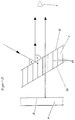
- einen stilisierten Querschnitt einer Kraftfahrzeuganzeigeeinheit mit Strahlengangdarstellung,
- Fig. 3
- eine Querschnittsansicht eines vergrößerten Ausschnitts einer Scheibe.
- Fig. 1
- a cross section of a motor vehicle display unit,
- Fig. 2
- a stylized cross section of a motor vehicle display unit with beam path representation,
- Fig. 3
- a cross-sectional view of an enlarged section of a disc.
Die in den Fig. 1 und 2 dargestellte Anzeigeeinheit besitzt ein zu der Position eines Beobachters 1 hin offenes Gehäuse 2, das in das Armaturenbrett eines Kraftfahrzeugs eingebaut ist. Im Bereich des Bodens 3 des Gehäuses 2 ist ein ein erstes Anzeigeelement 4 bildendes Instrument derart angeordnet, daß es mit seiner Anzeigeebene 5 zum Beobachter 1 hin zeigt.The display unit shown in FIGS. 1 and 2 has a
Zur Durchleuchtung des ersten Anzeigeelementes 4 sind hinter der Anzeigeebene 5 zwei Lichtquellen 6 angeordnet.To illuminate the
Unter einem Winkel von 30°geneigt ist zwischen der Anzeigebene 5 und dem Beobachter 1 eine ebene Scheibe 7 angeordnet. Dabei erstreckt sich der obere Rand der Scheibe 7 nahe der Anzeigeebene 5 parallel zu dieser, während der untere Rand der Scheibe 7 sich in einem größeren Abstand zur Anzeigeebene 5 befindet.A
In Aufnahmeöffnungen 8 der oberen Gehäusewand 9 sind auf der der Anzeigeebene 5 entfernteren Seite der Scheibe 7 zwei beleuchtbare zweite Anzeigeelemente 10 angeordnet, wobei diese obere Gehäusewand 9 von einer Hutze 11 überdeckt ist.Two lightable
Die Strahlenanzeigen der zweiten Anzeigeelemente 10 treffen unter einem solchen Einfallswinkel α auf die Scheibe 7, daß ihre Reflektion an der vorderen Grenzfläche 12 der Scheibe 7 zum Beobachter 1 hin gerichtet ist. Diese Reflektion wird von dem Beobachter als ein virtuelles Bild in einer Ebene gesehen, deren Abstand auf der dem Beobachter 1 abgewandten Seite der Scheibe 7 dem Abstand des jeweiligen zweiten Anzeigeelementes 10 von der Stelle der Scheibe 7 entspricht, auf die die Strahlen seiner Anzeige auftreffen.The beam displays of the
In der transparenten Scheibe 7 sind eine Vielzahl in geringem Abstand zueinander parallele Lamellen 13 geringer Dicke angeordnet. Die Längserstreckung der Lamellen 13 verläuft horizontal quer zur Blickrichtung 14 des Beobachters 1. In der Breite erstrecken sich die Lamellen 13 in Blickrichtung 14 von der vorderen Grenzfläche 12 zur hinteren Grenzfläche 15 der Scheibe 7. Dadurch wird durch die Lamellen 13 die Sichtbarkeit der Anzeigeebene 5 für den Beobachter 1 nicht behindert. Dies ist in Fig. 3 deutlich zu sehen.In the
Weiterhin ist in Fig. 3 auch deutlich zu sehen, daß der Anteil der auf die Scheibe 7 auftreffenden Strahlen, der nicht an der Grenzfläche 12 zum Beobachter 1 hin reflektiert wird, sondern transmittiv in die Scheibe eindringt, auf die Lamellen 13 auftrifft. Die lichtabsorbierend ausgebildeten Lamellen 13 verhindern, daß diese Strahlenanteile bis zur hinteren Grenzfläche 15 gelangen und dort ein zweites Mal reflektiert werden können.Furthermore, it can also be clearly seen in FIG. 3 that the proportion of the rays incident on the
Claims (10)
- A display unit, having a display plane (5) facing a given observer position and containing a first display element (4), and having a second display element (10), the display of which can be reflected towards the observer position (1) via a transparent plate (7) disposed between the observer position (1) and the display plane (5) and inclined approximately at an angle (α) in relation to a connecting line between the observer position (1) and the display element (4), characterised in that a plurality of lamellae (13), which are parallel to each other and are of low thickness which does not impair the visibility of the display plane from the observer position, is disposed in the transparent plate (7), the longitudinal span of which lamellae extends approximately transversely to the connecting line between the observer position (1) and the display element (4) and the span of width of which extends approximately in the direction of the connecting line between the observer position (1) and the display element (4), wherein the light rays of the display of the second display element impinge at an angle (α) on the transparent plan (7) such that their fractions of transmitted light entering the plate (7) impinge on the faces of the lamellae, which faces are of light-absorbing construction.
- A display unit according to claim 1, characterised in that the longitudinal span of the lamellae (13) is oriented approximately horizontally.
- A display unit according to either one of the preceding claims, characterised in that the width of the lamellae (13) approximately corresponds to the distance between the boundaries (12, 15) of the plate (7) in the direction of the connecting line between the observer position (1) and the display element.
- A display unit according to any one of the preceding claims, characterised in that the plate is a transparent film.
- A display unit according to any one of the preceding claims, characterised in that the second display element (10) is disposed in a shroud (11) which masks the incidence of light from above on the display plane (5).
- A display unit according to any one of the preceding claims, characterised in that the second display element (10) is a warning lamp.
- A display unit according to any one of claims 1 to 5, characterised in that the second display clement is a variable character display in the display.
- A display unit according to any one of the preceding claims, characterised in that the second display element is a transmissive liquid crystal display.
- A display unit according to any one of the preceding claims, characterised in that the first display element (4) is a display instrument of an instrument panel.
- A display unit according to any one of the preceding claims, characterised in that the first display element is a liquid crystal display.
Priority Applications (4)
| Application Number | Priority Date | Filing Date | Title |
|---|---|---|---|
| ES90123888T ES2060911T3 (en) | 1990-12-12 | 1990-12-12 | PRESENTATION UNIT. |
| DE59006722T DE59006722D1 (en) | 1990-12-12 | 1990-12-12 | Display unit. |
| EP90123888A EP0489953B1 (en) | 1990-12-12 | 1990-12-12 | Display unit |
| AU68322/90A AU636695B2 (en) | 1990-12-12 | 1990-12-20 | Display unit, in particular for motor vehicles |
Applications Claiming Priority (2)
| Application Number | Priority Date | Filing Date | Title |
|---|---|---|---|
| EP90123888A EP0489953B1 (en) | 1990-12-12 | 1990-12-12 | Display unit |
| AU68322/90A AU636695B2 (en) | 1990-12-12 | 1990-12-20 | Display unit, in particular for motor vehicles |
Publications (2)
| Publication Number | Publication Date |
|---|---|
| EP0489953A1 EP0489953A1 (en) | 1992-06-17 |
| EP0489953B1 true EP0489953B1 (en) | 1994-08-03 |
Family
ID=25635680
Family Applications (1)
| Application Number | Title | Priority Date | Filing Date |
|---|---|---|---|
| EP90123888A Expired - Lifetime EP0489953B1 (en) | 1990-12-12 | 1990-12-12 | Display unit |
Country Status (4)
| Country | Link |
|---|---|
| EP (1) | EP0489953B1 (en) |
| AU (1) | AU636695B2 (en) |
| DE (1) | DE59006722D1 (en) |
| ES (1) | ES2060911T3 (en) |
Families Citing this family (4)
| Publication number | Priority date | Publication date | Assignee | Title |
|---|---|---|---|---|
| JP2582525Y2 (en) * | 1992-08-21 | 1998-10-08 | 矢崎総業株式会社 | Display device for vehicles |
| FR2727559A1 (en) * | 1994-11-25 | 1996-05-31 | Magneti Marelli France | Dashboard panel display device for vehicles |
| DE102008058663B4 (en) * | 2008-11-22 | 2017-08-17 | Bayerische Motoren Werke Aktiengesellschaft | display unit |
| DE102015222389A1 (en) * | 2015-11-13 | 2017-05-18 | Bayerische Motoren Werke Aktiengesellschaft | Luminous element for a motor vehicle and shielding layer for a luminous element |
Citations (1)
| Publication number | Priority date | Publication date | Assignee | Title |
|---|---|---|---|---|
| DE2064025B2 (en) * | 1970-12-28 | 1973-12-06 | Adam Opel Ag, 6090 Ruesselsheim | Information provider for motor vehicles |
Family Cites Families (5)
| Publication number | Priority date | Publication date | Assignee | Title |
|---|---|---|---|---|
| FR2279122A1 (en) * | 1974-05-03 | 1976-02-13 | Thomson Csf | Window with shutter effect - is transparent for parallel lying beams and semi-transparent or opaque for other angles |
| GB2098147A (en) * | 1981-05-13 | 1982-11-17 | Ford Motor Co | Instrument panel for a vehicle |
| DE3233300A1 (en) * | 1982-09-08 | 1984-03-08 | Robert Bosch Gmbh, 7000 Stuttgart | Display device |
| JPS59176767A (en) * | 1983-03-25 | 1984-10-06 | 株式会社デンソー | Display for vehicle |
| EP0281436A1 (en) * | 1987-02-12 | 1988-09-07 | Martine Harraca-Roehl | Composite material and screens manufactured from this material |
-
1990
- 1990-12-12 EP EP90123888A patent/EP0489953B1/en not_active Expired - Lifetime
- 1990-12-12 DE DE59006722T patent/DE59006722D1/en not_active Expired - Fee Related
- 1990-12-12 ES ES90123888T patent/ES2060911T3/en not_active Expired - Lifetime
- 1990-12-20 AU AU68322/90A patent/AU636695B2/en not_active Ceased
Patent Citations (1)
| Publication number | Priority date | Publication date | Assignee | Title |
|---|---|---|---|---|
| DE2064025B2 (en) * | 1970-12-28 | 1973-12-06 | Adam Opel Ag, 6090 Ruesselsheim | Information provider for motor vehicles |
Also Published As
| Publication number | Publication date |
|---|---|
| AU6832290A (en) | 1992-07-02 |
| AU636695B2 (en) | 1993-05-06 |
| ES2060911T3 (en) | 1994-12-01 |
| DE59006722D1 (en) | 1994-09-08 |
| EP0489953A1 (en) | 1992-06-17 |
Similar Documents
| Publication | Publication Date | Title |
|---|---|---|
| DE4104233C2 (en) | Motor vehicle display device of the reflection type | |
| DE3634996C2 (en) | ||
| EP0157228B1 (en) | Indicator device | |
| DE2944537A1 (en) | INSTRUMENT LIGHTING DEVICE | |
| EP0489953B1 (en) | Display unit | |
| EP3622341B1 (en) | Motor vehicle display device and motor vehicle | |
| DE4327926C2 (en) | Vehicle display device with a display unit | |
| DE4126148C2 (en) | Display device for a vehicle | |
| DE3902673C2 (en) | Display display device for vehicles | |
| DE10160833B4 (en) | Display unit arranged in a motor vehicle | |
| DE2064025C3 (en) | Information provider for motor vehicles | |
| DE3032344A1 (en) | LIQUID CRYSTAL DISPLAYS | |
| DE3033141C2 (en) | Light guide in a display panel | |
| EP1812770B1 (en) | Viewing device mounted on a vehicle, particularly on a combat vehicle | |
| DE4132103A1 (en) | DISPLAY DEVICE FOR MOTOR VEHICLES | |
| DE2838509A1 (en) | ARRANGEMENT OF UMBRELLAS FOR BRINGING MOIRE PATTERNS | |
| DE3225362C1 (en) | Transparent pane for covering an instrument arranged underneath an obliquely extending windscreen in a vehicle dashboard | |
| EP1417111A1 (en) | Display unit | |
| DE3233300A1 (en) | Display device | |
| DE4303265C2 (en) | Display device for vehicles | |
| DE4123157C2 (en) | Display device for vehicles | |
| DE1630413A1 (en) | Anti-glare device for motor vehicles or the like. | |
| DE2318732C3 (en) | Arrangement for the direct illumination of fully anti-reflective display instruments in instrument panels, in particular of motor vehicles | |
| DE102008058663A1 (en) | Display unit for motor vehicle, has lamella foil that is arranged in display surface for adjusting display image in radiation direction, where foil additionally adjusts another display image in radiation direction aligned at viewer | |
| DE3934061A1 (en) | DISPLAY UNIT |
Legal Events
| Date | Code | Title | Description |
|---|---|---|---|
| PUAI | Public reference made under article 153(3) epc to a published international application that has entered the european phase |
Free format text: ORIGINAL CODE: 0009012 |
|
| 17P | Request for examination filed |
Effective date: 19910819 |
|
| AK | Designated contracting states |
Kind code of ref document: A1 Designated state(s): DE ES FR GB IT SE |
|
| 17Q | First examination report despatched |
Effective date: 19920930 |
|
| GRAA | (expected) grant |
Free format text: ORIGINAL CODE: 0009210 |
|
| AK | Designated contracting states |
Kind code of ref document: B1 Designated state(s): DE ES FR GB IT SE |
|
| ET | Fr: translation filed | ||
| REF | Corresponds to: |
Ref document number: 59006722 Country of ref document: DE Date of ref document: 19940908 |
|
| GBT | Gb: translation of ep patent filed (gb section 77(6)(a)/1977) |
Effective date: 19940920 |
|
| ITF | It: translation for a ep patent filed |
Owner name: STUDIO JAUMANN |
|
| PG25 | Lapsed in a contracting state [announced via postgrant information from national office to epo] |
Ref country code: SE Effective date: 19941103 |
|
| REG | Reference to a national code |
Ref country code: ES Ref legal event code: FG2A Ref document number: 2060911 Country of ref document: ES Kind code of ref document: T3 |
|
| PLBE | No opposition filed within time limit |
Free format text: ORIGINAL CODE: 0009261 |
|
| STAA | Information on the status of an ep patent application or granted ep patent |
Free format text: STATUS: NO OPPOSITION FILED WITHIN TIME LIMIT |
|
| 26N | No opposition filed | ||
| PGFP | Annual fee paid to national office [announced via postgrant information from national office to epo] |
Ref country code: FR Payment date: 19971113 Year of fee payment: 8 Ref country code: GB Payment date: 19971113 Year of fee payment: 8 |
|
| PGFP | Annual fee paid to national office [announced via postgrant information from national office to epo] |
Ref country code: ES Payment date: 19971216 Year of fee payment: 8 |
|
| REG | Reference to a national code |
Ref country code: ES Ref legal event code: PC2A |
|
| PG25 | Lapsed in a contracting state [announced via postgrant information from national office to epo] |
Ref country code: GB Free format text: LAPSE BECAUSE OF NON-PAYMENT OF DUE FEES Effective date: 19981212 |
|
| GBPC | Gb: european patent ceased through non-payment of renewal fee |
Effective date: 19981212 |
|
| PG25 | Lapsed in a contracting state [announced via postgrant information from national office to epo] |
Ref country code: FR Free format text: LAPSE BECAUSE OF NON-PAYMENT OF DUE FEES Effective date: 19990831 |
|
| REG | Reference to a national code |
Ref country code: FR Ref legal event code: ST |
|
| PG25 | Lapsed in a contracting state [announced via postgrant information from national office to epo] |
Ref country code: ES Free format text: LAPSE BECAUSE OF NON-PAYMENT OF DUE FEES Effective date: 19991213 |
|
| REG | Reference to a national code |
Ref country code: ES Ref legal event code: FD2A Effective date: 20000114 |
|
| PG25 | Lapsed in a contracting state [announced via postgrant information from national office to epo] |
Ref country code: IT Free format text: LAPSE BECAUSE OF NON-PAYMENT OF DUE FEES;WARNING: LAPSES OF ITALIAN PATENTS WITH EFFECTIVE DATE BEFORE 2007 MAY HAVE OCCURRED AT ANY TIME BEFORE 2007. THE CORRECT EFFECTIVE DATE MAY BE DIFFERENT FROM THE ONE RECORDED. Effective date: 20051212 |
|
| PGFP | Annual fee paid to national office [announced via postgrant information from national office to epo] |
Ref country code: DE Payment date: 20081219 Year of fee payment: 19 |
|
| PG25 | Lapsed in a contracting state [announced via postgrant information from national office to epo] |
Ref country code: DE Free format text: LAPSE BECAUSE OF NON-PAYMENT OF DUE FEES Effective date: 20100701 |