EP0488829B1 - Ink container and recording head having same - Google Patents
Ink container and recording head having same Download PDFInfo
- Publication number
- EP0488829B1 EP0488829B1 EP91311211A EP91311211A EP0488829B1 EP 0488829 B1 EP0488829 B1 EP 0488829B1 EP 91311211 A EP91311211 A EP 91311211A EP 91311211 A EP91311211 A EP 91311211A EP 0488829 B1 EP0488829 B1 EP 0488829B1
- Authority
- EP
- European Patent Office
- Prior art keywords
- ink
- absorbing material
- container
- fibers
- absorbing
- Prior art date
- Legal status (The legal status is an assumption and is not a legal conclusion. Google has not performed a legal analysis and makes no representation as to the accuracy of the status listed.)
- Expired - Lifetime
Links
Images


Classifications
-
- B—PERFORMING OPERATIONS; TRANSPORTING
- B41—PRINTING; LINING MACHINES; TYPEWRITERS; STAMPS
- B41J—TYPEWRITERS; SELECTIVE PRINTING MECHANISMS, i.e. MECHANISMS PRINTING OTHERWISE THAN FROM A FORME; CORRECTION OF TYPOGRAPHICAL ERRORS
- B41J2/00—Typewriters or selective printing mechanisms characterised by the printing or marking process for which they are designed
- B41J2/005—Typewriters or selective printing mechanisms characterised by the printing or marking process for which they are designed characterised by bringing liquid or particles selectively into contact with a printing material
- B41J2/01—Ink jet
- B41J2/17—Ink jet characterised by ink handling
- B41J2/175—Ink supply systems ; Circuit parts therefor
- B41J2/17503—Ink cartridges
- B41J2/1752—Mounting within the printer
- B41J2/17523—Ink connection
-
- B—PERFORMING OPERATIONS; TRANSPORTING
- B41—PRINTING; LINING MACHINES; TYPEWRITERS; STAMPS
- B41J—TYPEWRITERS; SELECTIVE PRINTING MECHANISMS, i.e. MECHANISMS PRINTING OTHERWISE THAN FROM A FORME; CORRECTION OF TYPOGRAPHICAL ERRORS
- B41J2/00—Typewriters or selective printing mechanisms characterised by the printing or marking process for which they are designed
- B41J2/005—Typewriters or selective printing mechanisms characterised by the printing or marking process for which they are designed characterised by bringing liquid or particles selectively into contact with a printing material
- B41J2/01—Ink jet
- B41J2/17—Ink jet characterised by ink handling
- B41J2/175—Ink supply systems ; Circuit parts therefor
- B41J2/17503—Ink cartridges
- B41J2/17506—Refilling of the cartridge
-
- B—PERFORMING OPERATIONS; TRANSPORTING
- B41—PRINTING; LINING MACHINES; TYPEWRITERS; STAMPS
- B41J—TYPEWRITERS; SELECTIVE PRINTING MECHANISMS, i.e. MECHANISMS PRINTING OTHERWISE THAN FROM A FORME; CORRECTION OF TYPOGRAPHICAL ERRORS
- B41J2/00—Typewriters or selective printing mechanisms characterised by the printing or marking process for which they are designed
- B41J2/005—Typewriters or selective printing mechanisms characterised by the printing or marking process for which they are designed characterised by bringing liquid or particles selectively into contact with a printing material
- B41J2/01—Ink jet
- B41J2/17—Ink jet characterised by ink handling
- B41J2/175—Ink supply systems ; Circuit parts therefor
- B41J2/17503—Ink cartridges
- B41J2/17513—Inner structure
-
- B—PERFORMING OPERATIONS; TRANSPORTING
- B41—PRINTING; LINING MACHINES; TYPEWRITERS; STAMPS
- B41J—TYPEWRITERS; SELECTIVE PRINTING MECHANISMS, i.e. MECHANISMS PRINTING OTHERWISE THAN FROM A FORME; CORRECTION OF TYPOGRAPHICAL ERRORS
- B41J2/00—Typewriters or selective printing mechanisms characterised by the printing or marking process for which they are designed
- B41J2/005—Typewriters or selective printing mechanisms characterised by the printing or marking process for which they are designed characterised by bringing liquid or particles selectively into contact with a printing material
- B41J2/01—Ink jet
- B41J2/17—Ink jet characterised by ink handling
- B41J2/175—Ink supply systems ; Circuit parts therefor
- B41J2/17503—Ink cartridges
- B41J2/17556—Means for regulating the pressure in the cartridge
Definitions
- the ink supply container capable of sufficiently supplying the ink for driving more than 10 ejection outlets or at the frequency not less than 5 KHz.
- Figure 15 shows the ink container, according to an embodiment of the present invention.
- the directions in which the fibers are extended is substantially parallel with the wall surface of the partition wall 4 and the wall portion 12A of the first chamber 3A.
- the longitudinal end portions of the fibers are assuredly contacted to the other wall portions 12B and 12C of the first chamber 3A which are perpendicular to the above wall surfaces.
- the central portion of the bundle of fibers at an end is in contact with one surface of the filter 8 for the supply pipe 9, as shown in the Figure.
- the central portion is press-contacted to the surface.
- the opening 4A of the partition wall 4 is away from the end of the supply pipe 9 by a proper distance, but they are sufficiently close to each other.
- the partition member may be in the form of a flexible elastic sheet mounted in the ink container.
- the state of ink, temperature or another ambient condition may be accomodated by the deformation of the elastic sheet so that the ink supply can be maintained.
- the formation of the air layer can be prevented between the ink absorbing material and the ink supply pipe of the recording head, and therefore, the deterioration of the resultant image or the occurence of the ejection failure can be assuredly prevented.
- the ink consumption for the recovery operation can be reduced, and the reliability of the ink jet cartridge is significantly improved.
- a gasket 601 seals the connecting portion between the ink container IT and the supply pipe 2200.
- a filter 700 is disposed at the container side end of the supply pipe.
- the ink jet cartridge IJC After the ink jet cartridge IJC is assembled, the ink is supplied from the inside of the cartridge to the chamber in the ink supply member 600 through a supply opening 1200, the whole 320 of the supporting member 300 and an inlet formed in the backside of the ink supply member 600. From the chamber of the ink supply member 600, the ink is supplied to the common chamber through the outlet, supply pipe and an ink inlet 1500 formed in the top plate 1300.
- the connecting portion for the ink communication is sealed by silicone rubber or butyl rubber or the like to assure the hermetical seal.
- first ink absorbing material 900 and a second ink absorbing material 902.
- the second ink absorbing material 902 has a high ink absorbing characteristics than the first ink absorbing material 900.
- the first ink absorbing material 900 is of urethane resin material
- the second ink absorbing material 902 is a one directional bundle of polyester fibers.
- Figure 17 shows a further embodiment wherein without the injecting opening 1000C of Figure 14, the same advantages can be provided using the air vent 1401.
- the end of the injecting pipe may be positioned to the porous material and the fibers. It is most preferable that the end is positioned correctly at the contact position.
- the end of the injecting pipe may be slightly away from the contact portion, as compared with the case of the initial supply of the ink thereto. In any case, the ink is injected at the neighborhood of the contact portion of the ink container.
- the ink supply side absorbing material of the recording head is constituted by fibers enclosed by a compressing tube, the capillary force is increased, so that the air is not easily accumulated below the filter.
- the liquid (ink) is ejected through an ejection outlet to produce at least one droplet.
- the driving signal is preferably in the form of a pulse, because the development and collapse of the bubble can be effected instantaneously, and therefore, the liquid (ink) is ejected with quick response.
- the driving signal in the form of the pulse is preferably such as diclosed in U.S. Patents Nos. 4,463,359 and 4,345,262.
- the temperature increasing rate of the heating surface is preferably such as disclosed in U.S. Patent No. 4,313,124.
Landscapes
- Ink Jet (AREA)
Description
- The present invention relates to an ink container and a recording head having the same usable with a recording apparatus for effecting recording operation using liquid ink in the form of a copying machine, facsimile machine, printer, compound machines or the like.
- U.S. Patents Nos. 4,095,237 and 4,306,245 disclose an ink container accommodating a liquid absorbing material occupying a part or entirety of the inside space thereof. In the latter mentioned patent, an end of the ink supply pipe communicating with an ink jet recording head is enclosed by a porous elastic material, and therefore, the ink supply performance is quite satisfactory, and is practically advantageous from the standpoint of preventing influences of the air introduced into the container.
- U.S. Patent No. 4,164,744 discloses a structure in which a coloring material is stored in a sealed container. This relates to a printing pen, and therefore, the introduction of the air in accordance with the consumption of the ink as in the case of the ink jet recording is not recognized.
- U.S. Patent No. 3,967,286 discloses an example using plural ink absorbing materials, more particularly an ink absorbing material in an ink container movable together with the recording head and a wick contacted to the ink absorbing material. However, it does not recognize the problem of the air introduction when the ink absorbing material is opened to the air.
- U.S. Patent No. 4,368,478 discloses provision of porous material in a common liquid chamber and/or ink container of the ink absorbing portion, and discloses that the fibers are suspended in the ink at a position upstream of the porous material in the direction of the ink supply so as to prevent the porous material from being clogged with the air bubbles. This however deals with the bubbles having passed through the ink supply pipe, but does not disclose the prevention of the introduction of the air into the recording head itself. This would be because the mechanism of the introduction of the bubbles is not analyzed sufficiently. It seems to base on the assumption that the introduced air is immediately conveyed into the recording head from the ink supply container. It involves the problem that the fibers and filler materials are deposited on the inner wall of the container and the problem of the insufficient ink supply when the number of ejection outlets is increased or when the apparatus is driven at a high speed.
- In the prior art, the ink supply container capable of sufficiently supplying the ink for driving more than 10 ejection outlets or at the frequency not less than 5 KHz.
- European patent application EP-A-419 192 proposes the internal structure of the container and the end position of the ink supply pipe wherein the influence by the introduction of the air to the ink supply performance is avoided. According to this proposal, the time required for the introduced air to reach the ink supply pipe end is significantly delayed, and is therefore, it is practical and good.
- With a container in which one porous ink absorbing material is used, it has been found that there is a limit to the delay which can be caused to the arrival of the air to the ink outlet portion (as seen from the ink supply container) along the inside of the absorbing material or along between the container wall and the absorbing material, and therefore, there is a limit to the reduction of the amount of the unusably remaining ink.
- Reference is made to US-A-4771295 which discloses an ink jet pen having multiple ink storage compartments each according to the preamble of
claim 1. - Various aspects of the present invention are concerned with stopping or delaying the introduction of air into an ink container so as to increase the ink suppliable period; minimising the amount of the unusable remaining ink when the ink container accommodates an ink absorbing sponge; arranging a plurality of ink absorbing materials so as to preclude the introduction of air to the recording head; enabling initial conditions to be properly set for an ink container having a plurality of absorbing materials; filling or refilling the container with ink; properly mounting a plurality of absorbing materials in the ink container before filling with ink; and sure operation of a multi-nozzle recording head having not less than 10 ejection outlets when recording on materials such as paper or cloth.
- According to an aspect of the present invention, there is provided an ink container, comprising: an ink discharging portion for discharging ink; an air vent; first liquid absorbing material for absorbing the ink therein; a second ink absorbing material, disposed between said air vent and said first absorbing material, for absorbing the ink, said first and second absorbing materials being at least partly in contact with each other, characterised in that said first liquid absorbing material includes fibrous material, the fibres of which extend in the direction of the contact surface between said first and second absorbing materials.
- The ink container may have a partition member for providing a first region for accommodating said first absorbing material and a second region for accommodating said second absorbing material and for directly communicating with said air vent, said partition member comprising an opening for permitting the contact between said first and second absorbing materials.
- The partition member may be of a flexible resin material enclosing the fibrous material and compressing them in a direction crossing with lengths of the fibrous materials. Preferably, the fibres of the first absorbing material are compressed in a direction crossing the lengths of the fibrous material, and a peripheral portion of a bundle of the fibrous material is contacted to said second absorbing material.
- The recording head is preferably constructed with more than 10 ejection outlets for ejecting ink and electrothermal transducers for the respective ejection outlets for creating bubbles through a film boiling by thermal energy and a common chamber for supplying the ink to the ejection outlets; an ink supply member for supplying the ink to the common chamber and provided with a filter at an ink receiving end thereof; a discharging portion for discharging the ink to the ink receiving end for said ink supply member; an air vent; a first absorbing material for absorbing ink therein, said first absorbing material comprising a number of fibrous materials in a compressed state and a flexible resin material enclosing member having an opening for exposing said fibrous materials, said first absorbing material exhibiting ink guiding property; a second absorbing material for absorbing the ink, disposed between said air vent and said first absorbing material, said second absorbing material being contacted to the fibrous material through the opening, said second absorbing material being compressed to provide vacuum, said second absorbing material being of continuous porous elastic material; and wherein in said discharging portion, a filter at the ink receiving end of said ink supply member is inserted into said first absorbing material in the direction of the length of the fibrous material, wherein a depth of the insertion is not less than 3 mm, wherein a diameter D of said ink supply member in a perpendicular cross-section with respect to a direction of the ink supply adjacent the filter of the ink supply member and a diameter d of said first absorbing material in the perpendicular cross-section adjacent to the filter satisfy d ≧ 1.5D, and the opening has an area of not less than 100 mm².
- Specific embodiments of the present invention will now be described by way of example with reference to the accompanying drawings, in which:-
- Figure 1 is a sectional view of an ink jet recording head according to an embodiment of the present invention.
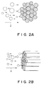
- Figure 2A schematically shows the mechanism of the air bubble introduction into a bundle of fibers (ink guiding members), when the air bubble is not capable of entering the bundle of the fibers.
- Figure 2B shows the same when the slight amount of the air bubbles can enter the bundle of the fibers, but the prevention is better than the conventional case.
- Figure 3 is a sectional view of an ink jet recording head according to another embodiment of the present invention.
- Figures 4A and 4B are a sectional view and a perspective view of an ink container.
- Figure 5 is a recording head assembly having the ink container shown in Figure 4, the head assembly being detachably mountable.
- Figure 6 is an exploded perspective view showing the internal structures of the ink accommodating container according to an embodiment of the present invention.
- Figure 7 is a sectional view showing the position and configuration of the absorbing material in the ink container and the position of the ink supply pipe.
- Figure 8 shows the internal structures of the ink accommodating container, which is a modification of Figure 6 embodiment.
- Figure 9 shows a structure of an ink container constituting an ink jet recording head.
- Figure 10 shows an ink jet cartridge according to an embodiment of the present invention.
- Figure 11 is a perspective view of an ink jet cartridge.
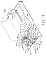
- Figure 12 is a schematic view of an ink jet recording apparatus.
- Figure 13A and 13B show a first ink absorbing material according to an embodiment of the present invention.
- Figures 14A and 14B show fibers extending in one direction, according to an embodiment of the present invention.
- Figure 15 shows the ink container, according to an embodiment of the present invention.
- Figure 16 shows an ink container illustrating a method of filling it with the ink.
- Figure 17 shows a major part in the method of Figure 16.
- Figure 18 shows a driving mechanism for a recording head.
- Referring to Figure 1, there is shown in cross-section an ink jet recording head according to an embodiment of the present invention.
-
Reference numeral 1 designates the recording head. Therecording head 1 comprises a main assembly having an ink ejecting function which will be described hereinafter and anintegral ink container 3 for supplying the recording ink to themain assembly 2. Theink container 3 functions to contain the recording liquid and has apartition wall 4 for providing afirst chamber 3A adjacent the main assembly and asecond chamber 3B adjacent an air vent of the container, thepartition wall 4 being integral with the casing of thecontainer 3. In this example, thepartition wall 4 extends substantially parallel to thewall portion 12A of thefirst chamber 3A. Apartial opening 4A is formed substantially at the center of thepartition wall 4 so that the two chambers communicate with each other. In thefirst chamber 3A, an end of asupply pipe 9 communicating with themain assembly 2 is inserted. The end of thesupply pipe 9 is provided with afilter 8 for preventing introduction of foreign matter into anink passage 10. The other end of thesupply pipe 10 constitutes anink discharger 7. Thesecond chamber 3B is provided with an opening 11 communicating with the ambience (air vent). Thesecond chamber 3B of theink container 3 is filled with a sponge 5 (second liquid absorbing material) made of continuous fine porous material such as polyurethane or the like having sufficient elasticity and liquid absorbing property. Thefirst chamber 3A is filled with fibers 6 (first absorbing material) in the form of a bundle of polyester resin fibers compressed an extended in the same direction. - It is desirable that the
fibers 6 extend in the direction toward the end of thesupply pipe 9 for the recording head, although they may be vent partially. This direction is advantageous since the ink supply property is improved. By constituting the bundle by a quite large number of fibers (8000, for example) and are compressed in the direction substantially perpendicular to the direction in which they are extended, so that the fine capillary forces can be provided. This is effective to delay the introduction of air bubbles, and simultaneously, the increase of the size of the air bubble can be prevented. If the fibers are compressed within a proper range, the ink guiding properties are enhanced in accordance with the consumption of the ink, and therefore, the supply of the ink into the bundle of the fibers is better, and the long term ink supply is assured. Even if the air bubbles are introduced, the good ink guiding property is effective to exclude the bubbles from the bundle of the fibers. This is also advantageous from the standpoint of the ink supply. - In this embodiment, the directions in which the fibers are extended is substantially parallel with the wall surface of the
partition wall 4 and thewall portion 12A of thefirst chamber 3A. The longitudinal end portions of the fibers are assuredly contacted to theother wall portions first chamber 3A which are perpendicular to the above wall surfaces. The central portion of the bundle of fibers at an end is in contact with one surface of thefilter 8 for thesupply pipe 9, as shown in the Figure. Preferably, the central portion is press-contacted to the surface. Theopening 4A of thepartition wall 4 is away from the end of thesupply pipe 9 by a proper distance, but they are sufficiently close to each other. In such an inkjet recording head 1, in accordance with the ejection of the ink from theink ejector 7, the ink is gradually consumed from the neighborhood of the filter at the end of thesupply pipe 9. The ink retained in the bundle of the fibers is subjected to the capillary force in the direction of the fibers, since the number of fibers are bundled and are extended in the same direction. Because of the capillary force, the ink smoothly moves along the fibers to thefilter 8, and are assuredly supplied from the end of theink supply pipe 9 to theink ejector 7 having an unshown ink ejecting means. - As will be understood from the foregoing, if the ink is assuredly supplied to the fibers, then the ink can be assuredly supplied to the ink ejector.
- For example, when the recording head is directed downwardly, the ink is supplied from the upper position, and is further supplied to the recording head by the fibers. In this case, the ink container may be sealed from the ambient air.
- Referring back to Figure 1, the ink contained in the
sponge 5 in thesecond chamber 3B is supplied by the vacuum through theopening 4A of thepartition wall 4 to that portion of the fibers in thefirst chamber 3A which is in contact with thesponge 5. In response to the consumption of the ink, the air enters thesecond chamber 3B through the air vent 11 so as to balance the pressures in the first andsecond chambers - As regards the relative characteristics of the
fibers 6 and thesponge 5 are as follows. - First, the ink supply to the recording head is accomplished by the
fibers 6, and thesponge 5 is between the fibers and the air vent. Second, the fibers and the sponge are in contact with or in press-contact with each other. Those two points are effective to delay the motion of the air in the container so that the ink can be more efficiently supplied to the recording head. - Third, the
fibers 6 are better than thesponge 5 in all of the capillary force, the ink retaining characteristics and the air excluding characteristics. Therefore, the introduction of the ink mainly occurs in thesponge 5 or the space between the sponge and the inner wall surface, so that the arrival of the air at thefirst chamber 3A can be significantly delayed. Therefore, the quantity of the wasteful ink which remains unusably in the container can be minimized. - Here, the advantageous effects of this embodiment which are common to the embodiments which will be described hereinafter, will be described, in comparison with the problems with the conventional structures. In the case in which the ink container is filled with compressed single sponge, it is known that the air enters the inside of the sponge by the vacuum of the sponge. However, before the air enters the inside of the sponge, the air main move along the inner surface of the container immediately after the consumption of the ink even to the extent to the recording head. Once this occurs, the air exists in the form of a bubble or bubbles, and the size thereof increases with the result of reduction of the ink supply performance. For the purpose of recovery, the air can be sucked out through the recording head ejection outlets, using a sucking pump. However, this provides only a temporary recovery at the cost of a large quantity of the ink. The same problem will be repeated. In this embodiment, or in the embodiments which will be described hereinafter, the time of the occurence of this problem can be significantly delayed, or can be completely eliminated.
- Since in this embodiment, the
sponge 5 and thefibers 6 are directly contacted through theopening 4A, the ink movement from thesponge 5 to thefibers 6 is smooth. - Preferable condition of the relation between the
sponge 5 and thefibers 6 in theopening 4A will be described. Since theopening 4A is defined by thepartition wall 4, and therefore, the opening is defined by the material which is more rigid than the sponge or the fibers, and therefore, not easily deformed. The thickness of thewall 4 is preferably small, but it still has a certain thickness. Therefore, one or both of thesponge 5 and thefibers 6 are bulged into the opening. In this embodiment, the opening area is not less than 100 mm², more particularly, 200 mm², and therefore, both of them are bulged for direct contact therebetween (Figure 1). Existence of thefibers 6 in the opening is effective to prevent movement of the air bubble from thesecond chamber 3B into thefirst chamber 3B, in other words, the reception of the ink by the fibers from thesponge 5 is enhanced.
Additionally, the existence of the sponge in the opening is effective to slightly shift the center of the vacuum toward theopening 4A, and therefore, the finally remaining quantity of the ink in the sponge can be further reduced. - In this embodiment, the state of contact between the
sponge 5 and thefibers 6 is preferable. Figures 7A and 7B show examples of the structures usable with the present invention, but the structure of Figure 7A is preferable. The preferable one is used in this embodiment. In Figure 7, the reference X indicates the direction in which the ink moves from thesponge 5 to thefibers 6, and therefore, the air bubble or bubbles also move in the direction X. In Figure 2A, the periphery of the bundle of thefibers 6, that is, the side of the bundle is contacted to thesponge 5. In other words, the direction of the ink supply from the sponge crosses with the ink guiding direction of the bundle of fibers. By this way of the contact, the introduction of the air into the fibers from the sponge can be further prevented. - When the cross-sectional surfaces of the
fibers 6 are contacted to the porous material, as shown in Figure 2B, the air bubble or bubbles retained in the bundle of fibers are confined in the fine clearances among the fibers, but the ink is more positively guided than the air bubble, and therefore, the ink can be supplied stably for a long term. Figure 2A arrangement is, however, better than Figure 2B arrangement. - Even if the air bubble enters the bundle of the fibers, the contacts of the ends of the fibers to the
wall surface portions first chamber 3A is effective to expel the air bubbles toward thewall portions filter 8 of thesupply pipe 9, and therefore, they are excluded from the neighborhood of thefilter 8. - In addition, the
opening 4A of thepartition wall 4 is formed at a position away from thesupply pipe 9 inlet by a proper distance, the ink in thesponge 5 is supplied through theopening 4A and is once retained by thefibers 6, and only then the ink is supplied to theink ejector 7 through thesupply pipe 9. This is also advantageous in that the introduction of the air from thesponge 5 into theink ejector 7. - Figure 3 is a sectional view of an ink jet recording head according to another embodiment of the present invention. In this Figure,
reference numeral 60 designates the ink jet recording head. The structure of therecording head 60 is substantially the same as therecording head 1 of Figure 1, and therefore, the same reference numerals are assigned to the elements having the corresponding functions, and the detailed description thereof is omitted for simplicity. In the recording head shown in Figure 3, theink container 3 is provide with twopartition walls ink container 3. By the twopartition walls first chamber 3A and twosecond chambers first chamber 3A. The first andsecond partition walls partial openings 61A and 62A substantially at the center thereof. In thefirst chamber 3A, an end of asupply pipe 9 in communication with theink passage 10 and therefore, with theink ejector 7 is inserted so that the portion of theink pipe 9 extends parallel with thepartition walls supply pipe 9 is provide with thefilter 8. In thefirst chamber 3A,fibers 6 are extended in the manner that the direction of the fibers are parallel with thepartition walls filter 8 at the end of thesupply pipe 9. Thesecond chambers sponges 5, respectively. Although in the Figure the air vent 11 is provided only for 3B of the second chambers, but the air vent is also provided for the othersecond chamber 3A. The firstabsorbing material 5 and the secondabsorbing material 6 are directly contacted through the twoopenings 61A and 62A, respectively, so that the ink is smoothly supplied from the absorbingmaterials 5 to the absorbingmaterial 6. In the liquidjet recording head 60, in accordance with the ejection of the ink through theink ejector 7, the ink is gradually consumed from the neighborhood of thefilter 8. Since thefibers 6 are extended in the same direction, the capillary forces are applied along the fibers. By the capillary force, the ink smoothly moves along the fibers to thefilter 8. Then, the ink is supplied to theink ejector 7 by the ink ejecting means not shown by way of thesupply pipe 9. The ink contained in the firstabsorbing material 5 in thesecond chambers absorbing material 6 in thefirst chamber 3A through theopenings 61A and 62A of thepartition walls first chamber 3A and in thesecond chambers - According to this embodiment, the opening area may be larger than in the first embodiment, the ink supply from the
sponge 5 to thefibers 6 is more efficient. Since thesponges 5 and thefibers 6 are directly contacted to each other through theopenings 61A and 62A, and therefore, the ink movement is small. The contacts at the respective positions between thefibers 6 and thesponges 5, are the same as in the case of Figure 2A. - In the foregoing embodiment, the partition in the ink container is provide by the
partition walls 61 and/or 62, but the partition may be provided inside ribs or a member joined to the inside surface of the container. - The partition member may be in the form of a flexible elastic sheet mounted in the ink container. In this case, by the deformation or displacement of the ink retaining material due to the air or gas in the ink container, the state of ink, temperature or another ambient condition may be accomodated by the deformation of the elastic sheet so that the ink supply can be maintained.
- The partition wall may be in the form of a cylinder in which the bundle of fibers is disposed, and porous material having the elasticity and liquid absorbing characteristics may be disposed between the partition wall and the ink container.
- Figures 4A, 4B and 5 shows an embodiment in which the partition member is integral with the fibers or the absorbing material, but is not fixed on the inside of the ink container.
- In Figures 4A, 4B and 5, the fibers and the sponge providing the vacuum in the ink supply action, are freely deformed when receiving the ink. In this embodiment, the stabilized vacuum and therefore, the ink supply is stabilized. By the partition member, the deformation of the fibers can be suppressed to stabilize the vacuum. Thus, the contact between the sponge and the fibers can be stabilized. The motion of the air between the different absorbing materials can be prevented. The partition member usable with this embodiment may be in the form of a sheer, plate. Preferably, it may be resin or aluminum sheet enclosing the fibers mostly to retard movement of the air or to stop it.
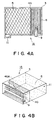
- Figures 4A and 4B are sectional view and perspective view of the ink container of a partition sheet according to an embodiment of the present invention. In the Figure reference 1A designates an ink container. The inside of the ink container 1A is divided into two chambers by the
partition member 40 having thepartial opening 40A. Adjacent the ink discharging portion of the ink container, the portion (one of the chambers) connected to the communicatingpipe 9 is filled withfibers 6. - The other chamber is filled with a
porous material 5 having elasticity and liquid absorbing property. Here, an air vent 11 is formed. Thepartition member 40 is made of flexible sheet, more particularly, polyethylene resin material in this embodiment. The ink is supplied through thepipe 9, and the quantity of the image inside the ink container 1A decreases in accordance with the ink supply. To permit this, the space of the ink is replaced with the air through the air vent 11. However, thesupply pipe 5 is isolated by thepartition member 40, and by the capillary action of thefibers 6, the neighborhood of thepipe 9 is filled with the ink, so that the ink supply is stabilized. In addition, since thepartition member 40 is made of flexible sheet, it can flexibly follow the internal pressure between the twomaterials fibers 6 and theporous material 5 is stabilized. - In Figures 4A and 4B, the ink supply direction by the fibers and the ink supply direction by the porous sponge cross with each other, as in Figure 2A example. The elastic porous material is usually compressed in the container and increases its volume when the air is introduced thereinto as a result of the ink consumption. To the contrary, the spaces between fibers expand when the ink is absorbed. When the ink is discharged therefrom, the spaces contract. Therefore, even if the volume of the bundle of the fibers changes slightly, the pressure by the porous material in the direction crossing with the fiber direction increases with the ink supply to the bundle of the fibers. This is effective to maintain the good contact between them, and is also effective to maintain the capillary force by the fibers. Therefore, the ink supply to the ink container is stabilized for a long period of time.
- Figure 5 shows a bubble jet cartridge BD01 available from Canon Kabushiki Kaisha, Japan having the ink container 1A shown in Figures 4A and 4B. The detailed description thereof will be made hereinafter in conjunction with Figures 10, 11 and 12. Here, the major parts only will be described.
- An ink jet cartridge IJC has a cartridge
main assembly 1000, an integral ink jet unit IJU and an integral ink jet head IJH. The cartridgemain assembly 1000 comprises the bundle of fibers, apartition member 40 having anopening 40A, aporous material 900 in the order named with compression. The ink supply from the container to the head IJH is effected through anink supply pipe 2200 penetrating thesupply port 1200 and through anink conduit 1600 to theink inlet port 1500 of the common chamber. The ink jet head IJH forms a bubble using thermal energy, as will be described hereinafter to eject the ink. It comprises plural ejection outlets and effects on-demand recording at high frequency. With the use of the ink container 1A, the ink can be stably supplied to the recording head from the ink container, and therefore, the bubble creation using the film boiling, can be stabilized. - The above embodiment uses a flexible sheet, but the same advantageous effects are provided when a flexible tube enclosing the fibers is used. It is preferable that the fibers are compressed in the tube, since then the bundle of the fibers can be easily mounted in the ink container.
- As described in the foregoing, Figures 4 and 5 embodiment is preferable in that the second absorbing material which is controlling with respect to the vacuum but which is deformed when receiving the ink from the first absorbing material or which is locally deformed, can be stabilized in the formation of the vacuum and in the supply of the ink. The formation of the second absorbing material is suppressed by the partition member, and the vacuum is stabilized. The contact between the first absorbing material and the second absorbing material can be stabilized, and the movement of the air or the like between the absorbing materials can be prevented.
- Figures 6, 7 and 8 shows the embodiment wherein a member enclosing the fibers is used. In Figures 6 - 8, the fibers are uniformly distributed relative to the ink discharging portion, and is advantageous in that the ink supply is made uniform to the ink discharging portion. In this embodiment, the bundle of fibers and the porous material are simultaneously mounted in the ink container, by which the deformation of the bundle of the fibers is prevented, thus stabilizing the contact between the absorbing materials. The ink can be supplied thereafter with stability without remaining the air, by which the ink communication at the contact portion is stabilized.
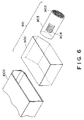
- Figure 6 shows an exploded view of the ink container. In this Figure, the
porous material 900 is different from the foregoing embodiments is cut at a corner to accommodate the bundle of the fibers. To the cut-away portion, anopening 904 of the cylindrical partition member is contracted with good close-contactness with thefibers 902. - The ink container comprises the
porous material 900 for retaining the ink, a bundle offibers 902 for retaining a constant amount of the ink, a tube for holding thefibers 902 and functioning as a partition member press-contacted to theporous material 901 and made of flexible material, anink supply port 904 for supplying the ink from theporous material 900 to thefibers 902. Thesupply port 904 is formed in thetube 903. - Figure 7 shows the ink container having the absorbing
material 901 in theink container 1000, and anink supply pipe 2200 for the ink jet unit IJU inserted in thefibers 902. - The
porous material 900 is made of polyurethane or the like capable of retaining the ink. It is preferably provided with inclined or recessed portion for permitting deformation of thefibers 902. The contact between theporous material 900 and the bundle of thefibers 902 may be made at plural surfaces or by a curved surface, rather than a single flat surface, so that the ink is stably supplied. The bundle offibers 902 functions to retain a sufficient quantity of the ink to supply the ink from theporous material 900 to theink supply pipe 2200 of the ink jet unit IJU. The fibers in this example are made of polyester resin or the like which provides large capillary force and which prevents introduction of the air. In addition, the direction of thefibers 902 are made parallel with the direction of theink supply pipe 2200. The outside of the bundle of the fibers is enclosed with aflexible tube 903 made of polyethylene or the like. - With this structure, the ink is smoothly supplied to the ink jet unit, and in addition, the air coming along the internal surface of the ink container IT can be stopped so as not to introduce the air into the absorbing material. In addition, as shown in Figure 7, the
ink supply pipe 2200 can perform its function if it is inserted into the bundle of thefibers 902. In order to prevent the leakage of the ink, the end of theink supplu pipe 2200 is press-contacted to thebundle 902. The press-contact is also preferable to maintain the stabilized ink supply. - It is preferable that the
porous material 900 and thebundle 902 are simultaneously mounted into the ink container IT. By the simultaneous mounting, the undesirable deformation of thebundle 902 can be prevented, and the contact area between theporous material 901 and thebundle 902 can be stabilized. In addition, the non-uniform distribution of the ink can be prevented. Furthermore, the air is prevented from remaining, thus assuring the ink movement through the contact area is assured. - With this structure, the constant quantity of the ink can be retained at all times in the bundle of fibers adjacent the end of the
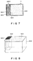
ink supply pipe 2200 for supplying the ink to the ink jet head unit IJU. Therefore, the insufficient supply of the ink to the ink jet unit IJU can be prevented. Thebundle 902 retains the ink by the capillary action, and therefore, the retaining characteristics are immune to the temperature, humidity, pressure and impact thereto. Therefore, the conventional problem of the insufficient ink supply due to the ink retaining charateristics change resulting from the change in the ambient condition, can be prevented. - Figure 8 shows the ink container according to a further embodiment of the present invention. In this embodiment, the bundle of the
fibers 902 is in the form of a rectanglular cylinder. To accomodate it, theporous material 900 has a rectangular cut-away portion. The cut-away portion receives the bundle offibers 902 enclosed with the partition member. The bundle having the rectangular cross-section is also usable with the same advantageous effects as in the foregoing embodiments. - As described in the foregoing, according to this embodiment of the present invention, the fibers are disposed between the inside surface of the container and the porous material to stably position the fibers relative to the porous material, thus preventing insufficient ink supply. Using the porous material enclosing the bundle of the fibers, is preferable in that the ink retaining or ink supplying performance to the contact area is enhanced, so that the efficiency of the ink supply is improved.
- In addition, by the use of the fibers, the formation of the air layer can be prevented between the ink absorbing material and the ink supply pipe of the recording head, and therefore, the deterioration of the resultant image or the occurence of the ejection failure can be assuredly prevented. Thus, the ink consumption for the recovery operation can be reduced, and the reliability of the ink jet cartridge is significantly improved. Referring to Figures 9 - 14, a preferable embodiment of the ink jet recording head and an ink jet recording apparatus will be described. In this embodiment, the ink absorbing material in the recording liquid container comprises a first absorbing material exhibiting higher liquid absorbing property and disposed adjacent to the recording liquid supplying pipe (ink discharging side) and a second absorbing material exhibiting lower ink absorbing property than the first liquid absorbing material. The first absorbing material and the second absorbing material are at least partly contacted to each other so as to provide the vacuum.
- Figure 9 shows an ink container constituting a part of the liquid jet recording head.
- Referring to Figures 10, 11 and 12, the description will be made, before describing the ink container of Figure 9, as to an ink jet unit IJU, an ink jet head IJH, an ink container IT, an ink jet cartridge IJC, an ink jet recording apparatus main assembly IJRA, a carriage HC, to which the present invention is suitably incorporated.
- As will be understood from Figure 11 which is a perspective view, the ink jet cartridge IJC of this embodiment has a large ink absorbing region by projecting the ink jet unit IJU slightly beyond the front surface of the ink container IT. The ink jet cartridge IJC is supported by an unshown positioning means of the carriage HC in the ink jet recording apparatus main assembly IJRA and by electric contacts. The ink jet cartridge IJC is detachably mountable to the carriage HC, wherein the ink can be refilled.
- The ink jet unit IJU is of an ink jet recording type using electrothermal transducers which generate thermal energy, in response to electric signals, to produce film boiling of the ink.
- Referring to Figure 10, the unit comprises a
heater board 100 having electrothermal transducers (ejection heaters) arranged in a line on an Si substrate and electric head lines made of aluminum or the like to supply electric power thereto. The electrothermal transducer and the electric leads are formed by a film forming process. Awiring board 200 is associated with theheater board 100 and includes wiring corresponding to the wiring of the heater board 100 (connected by the wire bonding technique, for example) andpads 201 disposed at an end of the wiring to receive electric signals from the main assembly of the recording apparatus. - A
top plate 1300 is provided with grooves which define partition walls for separting adjacent ink passages and a common liquid chamber for accommodating the ink to be supplied to the respective ink passages. Thetop plate 1300 is formed integrally with anink jet opening 1500 for receiving the ink supplied from the ink container IT and directing the ink to the common chamber, and also with anorifice plate 400 having the plurality of ejection outlets corresponding to the ink passages. The material of the integral mold is preferably polysulfone, but may be another molding resin material. - A supporting
member 300 is made of metal, for example, and functions to support a backside of thewiring board 200 in a plane, and constitutes a bottom plate of the ink jet unit IJU. A confiningspring 500 is in the form of "M" having a central portion urging to the common chamber with a light pressure, and aclamp 501 urges concentratedly with a line pressure to a part of the liquid passage, preferably the part in the neighborhood of the ejection outlets. The confiningspring 500 has legs for clamping theheater board 100 and thetop plate 1300 by penetrating through theopenings 3121 of the supportingplate 300 and engaging the back surface of the supportingplate 300. Thus, theheater board 100 and thetop plate 1300 are clamped by the concentrated urging force by the legs and theclamp 501 of thespring 500. The supportingplate 300 has positioningopenings positioning projections 1012 and positioning and fuse-fixingprojections 1800 anf 1801 of the ink container IT. It further includesprojections - In addition, the supporting
member 300 has ahole 320 through which anink supply pipe 2200, which will be described hereinafter, is penetrated for supplying ink from the ink container. Thewiring board 200 is mounted on the supportingmember 300 by bonding agent or the like. The supportingmember 300 is provided withrecesses positioning projections - As shown in Figure 11, the assembled ink jet cartridge IJC has a head projected portion having three sides provided with plural
parallel grooves recesses projections member 800 having theparallel grooves 3000, as shown in Figure 11, constitutes an outer casing of the ink jet cartridge IJC and cooperates with the ink container to define a space for accommodating the ink jet unit IJU. Theink supply member 600 having theparallel groove 3001 has anink conduit pipe 1600 communicating with the above-describedink supply pipe 2200 and cantilevered at thesupply pipe 2200 side. In order to assure the capillary action at the fixed side of theink conduit pipe 1600 and theink supply pipe 2200, a sealingpin 602 is inserted. - A
gasket 601 seals the connecting portion between the ink container IT and thesupply pipe 2200. Afilter 700 is disposed at the container side end of the supply pipe. - The
ink supply member 600 is molded, and therefore, it is produced at low cost with high positional accuracy. In addition, the cantilevered structure of theconduit 1600 assures the press-contact between theconduit 1600 and theink inlet 1500 even if theink supply member 600 is mass-produced. - In this embodiment, the complete communicating state can be assuredly obtained simply by flowing sealing bonding agent from the ink supply member side under the press-contact state. The
ink supply member 600 may be fixed to the supportingmember 300 by inserting and penetrating backside pins (not shown) of theink supply member 600 through theopenig member 300 and by heat-fusing the portion where the pins are projected through the backside of the supportingmember 300. The slight projected portions thus heat-fused are accommodated in recesses (not shown) in the ink jet unit (IJU) mounting side surface of the ink container IT, and therefore, the unit IJU can be correctly positioned. - The ink container comprises a
main body 1000, a firstink absorbing material 900, a secondink absorbing material 902 and acover member 1100 for sealing the cartridge after the absorbingmaterials 901 are inserted through a side opposite from the unit mounting side of theassembly 1000. Theink absorbing material 900 is inserted into themain body 1000 from the side opposite from the unit (IJU) mounting side, and thereafter, thecover member 1100 seals the main body. - The second
absorbing material 902 is enclosed with aflexible sheet 903 having an opening (not shown), and the opening portion is press-contacted to the firstink absorbing material 900, when it is disposed in themain assembly 1000. Anink supply opening 1200 functions to supply the ink to the unit IJU comprising the various elements 100 - 600. The opening also functions as an injection port for supplying the ink to the absorbingmaterials main assembly 1000 of the cartridge. - In this embodiment, the ink may be supplied through an air vent port and this supply opening. In order to good supply of ink,
ribs 2300 is formed on the inside surface of themain body 1000, and ribs 2301 and 2302 are formed on the inside of thecover member 1100, which are effective to provide within the ink container an ink existing region extending continuously from the air vent port side to that corner portion of the main body which is most remote from theink supply opening 1200. The number of theribs 2300 in this embodiment is four, and theribs 2300 extend parallel to a movement direction of the carriage adjacent the rear side of the main body of the ink container, by which the absorbingmaterial 900 is prevented from closely contacted to the inner surface of the rear side of the main body. Thepartial ribs cover member 1100 at a position which is substantially an extension of theribs 2300, however, as contrasted to thelarge rib 2300, the size of the ribs 2301 an 2302 are small as if it is divided ribs, so that the air existing space is larger with theribs rib 2300. The ribs 2302 and 2301 are distributed on the entire area of thecover member 1100, and the area thereof is not more than one half of the total area. Because of the provisions of the ribs, the ink in the corner region of the ink absorbing material which is most remote from thesupply opening 1200 can be stably and assuredly supplied to the inlet opening by capillary action. The cartridge is provided with anair vent port 1401 for communication between the inside of the cartridge with the outside air. Inside thevent port 1401, there is awater stopping material 1400 to prevent the inside ink from leaking outside through thevent port 1401. - The ink accommodating space in the ink container IT is substantially rectangular parallelepiped, and the long side faces in the direction of carriage movement, and therefore, the above-described rib arrangements are particularly effective. When the long side extends along the movement direction of the carriage, or when the ink containing space is in the form of a cube, the ribs are preferably formed on the entire surface of the inside of the
cover member 1100 to stabilize the ink supply from theink absorbing material 900. The cube configuration is preferable from the standpoint of accommodating as much ink as possible in the limited space. However, from the standpoint of using the ink with minimum an available part in the ink container, the provisions of the ribs formed on the two surfaces constituting a corner. - In this embodiment, the inside ribs 2301 and 2302 of the ink container IT are substantially uniformly distributed in the direction of the thickness of the ink absorbing material having the rectangular parallelepiped configuration. Such a structure is significant, since the air pressure distribution in the ink container IT is made uniform when the ink in the absorbing material is consumed so that the quantity of the remaining unavailable ink is substantially zero. It is preferable that the ribs are disposed on the surface or surfaces outside a circular are having the center at the projected position on the
ink supply opening 1200 on the top surface of the rectangular ink absorbing material and having a radius which is equal to the long side of the rectangular shape, since then the ambient air pressure is quickly established for the ink absorbing material present outside the circular arc. The position of the air vent of the ink container IT is not limited to the position of this embodiment if it is good for introducing the ambient air into the position where the ribs are disposed. - After the ink jet cartridge IJC is assembled, the ink is supplied from the inside of the cartridge to the chamber in the
ink supply member 600 through asupply opening 1200, the whole 320 of the supportingmember 300 and an inlet formed in the backside of theink supply member 600. From the chamber of theink supply member 600, the ink is supplied to the common chamber through the outlet, supply pipe and anink inlet 1500 formed in thetop plate 1300. The connecting portion for the ink communication is sealed by silicone rubber or butyl rubber or the like to assure the hermetical seal. - In this embodiment, the
top plate 1300 is made of resin material having resistivity to the ink, such as polysulfone, polyether sulfone, polyphenylene oxide, polypropylene. It is integrally molded in a mold together with anorifice plate portion 400. - As described in the foregoing, the integral part comprises the
ink supply member 600, thetop plate 1300, theorifice plate 400 and parts integral therewith, and theink container body 1000. Therefore, the accuracy in the assembling is improved, and is convenient in the mass-production. The number of parts is smaller than inconventional device, so that the good performance can be assured. - Figure 12 is a perspective view of an ink jet recording apparatus IJRA in which the present invention is used. A
lead screw 5005 rotates by way of a drive transmission gears 5011 and 5009 by the forward and backward rotation of a drivingmotor 5013. Thelead screw 5005 has ahelical groove 5004 with which a pin (not shown) of the carriage HC is engaged, by which the carriage HC is reciprocable in directions a and b. Asheet confining plate 5002 confines the sheet on the platen over the carriage movement range. Homeposition detecting means lever 5006 of the carriage, in response to which the rotational direction of themotor 5013 is switched. A supporting member 5016 supports the front side surface of the recording head to acapping member 5022 for capping the recording head. Sucking means 5015 functions to suck the recording head through theopening 5023 of the cap so as to recover the recording head. - A
cleaning blade 5017 is moved toward front and rear by a movingmember 5019. They are supported on the supportingframe 5018 of the main assembly of the apparatus. The blade may be in another form, more particularly, a known cleaning blade. Alever 5021 is effective to start the sucking recovery operation and is moved with the movement of acam 5020 engaging the carriage, and the driving force from the driving motor is controlled by known transmitting means such as clutch or the like. - The capping, cleaning an sucking operations can be performed when the carriage is at the home position by the
lead screw 5005, in this embodiment. However, the present invention is usable in another type of system wherein such operations are effected at different timing. The individual structures are advantageous, and in addition, the combination thereof is further preferable. - In Figure 9, there are shown a first
ink absorbing material 900 and a secondink absorbing material 902. The secondink absorbing material 902 has a high ink absorbing characteristics than the firstink absorbing material 900. In this embodiment, the firstink absorbing material 900 is of urethane resin material, and the secondink absorbing material 902 is a one directional bundle of polyester fibers. - The second
ink absorbing material 902 is enclosed with aflexible sheet 903 having an opening (not shown) at a part thereof. The first and secondink absorbing materials main assembly 1000 of the ink container cartridge. - Figures 13A, 13B, 14A and 14B show the first
ink absorbing material 900 and the secondink absorbing material 902 according to an embodiment of the present invention. - In Figures 13A and 13B, the first
ink absorbing material 900 is partially cut away at the portion having the dimension of l₁, l₂ at a corner to provide a stepped portion. The lengths l₁ and l₂ are smaller than the secondink absorbing material 902 so as to press-contact the secondabsorbing material 902 of Figure 14 to the inside surface of the ink container. In this embodiment, the diameter of the secondink absorbing material 902 is 16 mm, and the lengths l₁ and l₂ and 11 mm and 12 mm, respectively. With these dimensions, the press-contact between the firstink absorbing material 900 and the secondink absorbing material 902 was satisfactory at the cut-away portion of the absorbingmaterial 900. - In Figure 14, the area of the
opening 904 of theflexible sheet 903 where the firstink absorbing material 900 and the secondink absorbing material 902 are directly press-contacted is determined on the basis of the characteristics of the recording head and the rate of ink supply required. - In this embodiment, the length l₃ and l₄ are preferably 12 mm and 16 mm, respectively. If the area of the
opening 904 is not less than 100 mm², thefibers 902 are assuredly projected slightly through the opening, as shown in Figure 14B, so that the side of the bundle of the fibers are partly formed into a projection orbulge 902A. Thebulge 902A functions to receive the ink efficiently and not to receive the air. - As described in the foregoing, according to this embodiment, when the desired content of the ink is obtained by partly discharging the ink after the ink is supplied, the press-contact of the flexible sheet enclosing the one directional fibers to the inside surface of the ink cartridge is effective to shut the air coming along the surface, and therefore, the introduction of the air into the ink jet unit can be prevented, thus stabilizing the ink supply.
- The ink is discharged or removed from the absorbing material having the lower absorbing characteristics (porous material or the like) than the one directional fibers, and therefore, the fibers are not influenced by the non-uniform distribution of the ink at the time of the ink discharge. As a result, the introduction of the air into the ink jet unit can be prevented, thus providing the smooth ink supply.
- Figure 15 illustrates a further embodiment of the present invention. The ink container IT generally comprises a main assembly 100A and a cover 8 A for covering the opening of the main assembly 100A.
- Into the
main assembly 1000A, an end of anink supply pipe 2200 is inserted through one wall thereof. Theink supply pipe 2200 functions as an ink supply passage for supplying the ink in the main assembly 100A to the ink ejector of the ink jet head. In themain assembly 1000A, there are a firstabsorbing material 900 made of porous material such as polyurethane resin or the like to retain the ink and a secondabsorbing material 905 comprising a bundle of one directional fibers 902 (not shown) may be polyester resin or the like and aflexible material tube 903 made of polyethylene resin or the like and enclosing the bundle of the fibers. They are compressed in the containermain assembly 1000A. Thetube 903 enclosing the secondabsorbing material 905 is provide with anopening 904 functioning as an ink supply port from the firstabsorbing material 900 to the inside 905 of the second absorbing material. Thefibers 902 extend in the direction of the length of thetube 903, and the bundle thereof is compressed in the direction substantially perpendicular to the direction in which the fibers extend. A sealing member 1000B is effective to prevent the leakage of the ink. - In this structure, the porous material constituting the first
absorbing material 900 is contacted to the peripheral portion of the bundle of thefibers 902 constituting the secondabsorbing material 905 through theopening 904 of thetube 903, and therefore, the ink supply from the firstabsorbing material 904 to theseond absorbing material 905 is assured. The end of the ink supply pipe 220 is pressed into the central portion of an end of thebundle 902 enclosed by thetube 903, so that the end is positioned in the containermain assembly 1000A. - It is preferable that the ink container IT has the
opening 904 in thetube 903, the opening having the area S which is not less than 100 mm². The depth of insertion of the ink supply pipe 220 at the end into the tube 903 (l) is preferably not less than 3 mm, and the inside diameter D of thetube 903 is not less than 1.5 (further preferably 2.0) times the inside diameter d of theink supply pipe 5 at the end. By satisfying them, the ink supply is stabilized at high efficiency without influence to the ejection performance by the ink ejector. These conditions are preferably since they are satisfied, the advantageous effects of the present invention are assured with the manufacturing error or the like. The high rate ink supply is possible to permit high speed recording operation. It is further preferable that the supply pipe is inserted into the fibers at the center of the bundle thereof, and also it is preferable that the direction in which the fibers extend is codirectional with the supply pipe. The diameter of the supply pipe is preferably not more than 10 times, or further preferably 5 times. - In this manner, the concentrated ink supply by the bundle of the fibers with the difference of not less than 3 mm, if effective to delay the arrival of the air to the end of the supply pipe almost until the use-up of the ink.
- The contact in the area not less than 100 mm² between the first absorbing material of the porous material and the second absorbing material of fibers, is effective to prevent the discontinuance of the ink supply path between the first absorbing material to the second absorbing material event when the remaining amount of the ink reduces or even when the ambient condition changes.
- Figures 16 and 17 illustrate a further embodiment. In the present invention, the ink supply is better than in the conventional structure even if the ink container contains small amount of air. However, at the initial stage of the use of the ink container, it is preferable that there is no air adjacent the contact area between the different absorbing materials. In this embodiment, the ink can be supplied or re-supplied into the container so that the air does not exists in the neighborhood of the contact portion between the two ink absorbing materials. In order to solve the problems, the recording head of this embodiment is characterized by the ink injecting opening formed in the ink container wall in the neighborhood of the opening for permitting direct contact between the porous material and the bundle of the fibers.
- With this structure, the discharge outlet of the ink container is sealed; the air is removed through the above-described
air vent 1401 until the vacuum of the inside of the ink container is sufficient; theair vent 1401 is closed; and the ink is injected through the injection opening. By doing so, the air does not remain in the ink absorbing material, particularly the portion between the absorbing materials. - In addition, a small diameter pipe is inserted into the porous material through the air vent, and the ink is injected through the pipe so that the air does not remain in the ink container.
- Figure 16 shows a further embodiment. In this Figure, the same reference numerals as in the foregoing embodiments are assigned to the elements having the corresponding functions, and the detailed description thereof are omitted.
- An ink injecting opening 1000C is provided in the ink container itself and is formed adjacent the
opening 904 of thetube 903 enclosing thefibers 902 at the side where theporous material 900 is formed. When the ink is supplied through the air vent, the air remains in the neighborhood of theopening 904 of thetube 903. However, by injecting the ink through the injection opening 1000C, the air in the porous absorbing material is easily moved to the air vent. In addition, the ink is supplied into the fibers through theopening 904, and therefore, the air removal from the contact area is assured. - By injecting the ink through the injection opening 1000C adjacent the
opening 904, the quantity of the remaing air can be reduced. - It is preferable that the ink injecting opening 1000C is provided with a removable cap permitting the re-injection of the ink, so that the recording head is reusable.
- Figure 17 shows a further embodiment wherein without the injecting opening 1000C of Figure 14, the same advantages can be provided using the
air vent 1401. It is preferable that the injection end of the liquid injecting pipe is positioned to the neighborhood of the contact area between the different ink absorbing materials, and the ink is supplied there. The end of the injecting pipe may be positioned to the porous material and the fibers. It is most preferable that the end is positioned correctly at the contact position. When the ink container is to be refilled, there exists the remaining ink in the contact portion, and therefore, the end of the injecting pipe may be slightly away from the contact portion, as compared with the case of the initial supply of the ink thereto. In any case, the ink is injected at the neighborhood of the contact portion of the ink container. - By inserting the
small diameter pipe 100 through the air vent, as shown in Figure 17, the same advantageous effects as in the foregoing embodiment can be provided. - As described in the foregoing, in the ink container having plural absorbing materials, the ink injecting opening is disposed adjacent the opening permitting the motion of the ink between the absorbing materials, and therefore, the quantity of the ink remaining in the container in the absorbing materials can be reduced.
- Since the ink supply side absorbing material of the recording head is constituted by fibers enclosed by a compressing tube, the capillary force is increased, so that the air is not easily accumulated below the filter.
- Without use of this method, the ink container becomes non-usable in one hour at 60 °C acceleration test due to the introduction of the air, but with the use of this method, it is extended to 16 hours.
- Figure 18 shows an ink jet recording apparatus having electrothermal transducers with plural ejection outlets, which is suitably usuable with the present invention.
- An ink jet head H comprises at least 10 ejection outlets, the electrothermal transducers EH corresponding to the injection outlets and a common liquid chamber C commonly communicating with the ejection outlets. A supply pipe SP functions to supply the ink from the ink containing portion to the common liquid chamber. A selection circuit EC functions to individually or simultaneously driving the electrothermal transducers EH. The recording heads has a common electrode and is driven by a driving means DM. A recording signal generators RS comprises reading means, communication means, receiver or a host computer or the like. The driving means DM is responsive to the recording signal RS, and is capable of driving the electrothermal transducers at the driving frequency of not less than 5 KHz. The direction of the ink supply in the pipe SP is indicated by a reference Y.
- In Figure 18, the ink container has the structure of any one of the foregoing embodiments. The fibers are indicated by ITA, the partition member is indicated by HM, the opening of the partition member is indicated by TH, the air vent is indicated by AH, the ink retaining portion is indicated by ITB, which may be in the form of the above described porous material or the cavity.
- In this embodiment, an end of the ink supply pipe is tapered, and a filter is provided for the end, so that the filter is inclined relative to the direction of the fibers. The depth of the insertion in the partition member HM is l₁ at minimum and l₂ at the maximum. In this case, the insertion depth l is considered as


- The typical structure and the operational principle of preferably the one disclosed in U.S. Patent Nos. 4,723,129 and 4,740,796. The principle is applicable to a so-called on-demand type recording system and a continuous type recording system particularly however, it is suitable for the on-demand type because the principle is such that at least one driving signal is applied to an electrothermal transducer disposed on a liquid (ink) retaining sheet or liquid passage, the driving signal being enough to provide such a quick temperature rise beyond a departure from nucleation boiling point, by which the thermal energy is provide by the electrothermal transducer to produce film boiling on the heating portion of the recording head, whereby a bubble can be formed in the liquid (ink) corresponding to each of the driving signals. By the development and collapse of the the bubble, the liquid (ink) is ejected through an ejection outlet to produce at least one droplet. The driving signal is preferably in the form of a pulse, because the development and collapse of the bubble can be effected instantaneously, and therefore, the liquid (ink) is ejected with quick response. The driving signal in the form of the pulse is preferably such as diclosed in U.S. Patents Nos. 4,463,359 and 4,345,262. In addition, the temperature increasing rate of the heating surface is preferably such as disclosed in U.S. Patent No. 4,313,124.
- The structure of the recording head may be as shown in U.S. Patent Nos. 4,558,333 and 4,459,600 wherein the heating portion is disposed at a vent portion in addition to the structure of the combination of the ejection oulet, liquid passage and the electrothermal transducer as disclosed in the above-mentioned patents. In addition, the present invention is applicable to the structure disclosed in Japanese Laid-Open Patent Application Publication No. 123670/1984 wherein a common slit is used as the ejection outlet for plural electrothermal transducers, and to the structure disclosed in Japanese Laid-Open Patent Application No. 138461/1984 wherein an opening for absorbing pressure wave of the thermal energy is formed corresponding to the ejecting portion. This is because, the present invention is effective to perform the recording operation with certainty and at high efficiency irrespective of the type of the recording head.
- The present invention is effectively applicable to a so-called full-line type recording head having a length corresponding to the maximum recording width. Such a recording head may comprise a single recording head and a plural recording head combined to cover the entire width.
- In addition, the present invention is applicable to a serial type recording head wherein the recording head is fixed on the main assembly, to a replaceable chip type recording head which is connected electrically with the main apparatus and can be supplied with the ink by being mounted in the main assembly, or to a cartridge type recording head having an integral ink container.
- The provision of the recovery means and the auxiliary means for the preliminary operation are preferable, because they can further stabilize the effect of the present invention. As for such means, there are capping means for the recording head, cleaning means therefor, pressing or sucking means, preliminary heating means by the ejection electrothermal transducer or by a combination of the ejection electrothermal transducer and additional heating element and means for preliminary ejection not for the recording operation, which can stabilize the recording operation.
- As regards the kinds of the recording head mountable, it may be a single corresponding to a single color ink, or may be plural corresponding to the plurality of ink materials having different recording color or density. The present invention is effectively applicable to an apparatus having at least one of a monochromatic mode mainly with black and a multi-color with different color ink materials and a full-color mode by the mixture of the colors which may be an integrally formed recording unit or a combination of plural recording heads.
- As described in the foregoing, even if the air is introduced into the first ink absorbing material, it is not introduced into the second ink absorbing material constituted by fibers extended in the same direction. Therefore, the air is not accumulated in the neighborhood of the supply port. Therefore, the ink supply is not stopped by the air, thus stably supplying the ink.
- In addition, plural absorbing materials having different configurations and materials are disposed with a partition wall therebetween, which is integral with the inside wall of the container. Therefore, the motion of the air due to the consumption of the ink can be delayed, so that the improper ink supply occurrence can be significantly delayed or completely avoided. Therefore, ink can be consumed efficiently in connection with the amount of the ink contained in the container.
Claims (13)
- An ink container, comprising: an ink discharging portion for discharging ink; an air vent (11); first liquid absorbing material (6) for absorbing the ink therein; a second ink absorbing material (5), disposed between said air vent and said first absorbing material, for absorbing the ink, said first and second absorbing materials being at least partly in contact with each other, characterised in that said first liquid absorbing material includes fibrous material, the fibres of which extend in the direction of the contact surface between said first and second absorbing materials.
- A container as claimed in Claim 1, further comprising a partition member (4) for providing a first region for accommodating said first absorbing material and a second region for accommodating said second absorbing material and for directly communicating with said air vent, said partition member comprising an opening for permitting the contact between said first and second absorbing materials.
- An ink container as claimed in Claim 1 or 2, characterised in that said first absorbing material comprises fibres which are compressed.
- A container as claimed in Claim 1, 2 or 3, characterised in that said second absorbing material comprising a continous porous elastic material which is compressed.
- A container as claimed in any one of Claims 1 to 4, characterised in that the contact surface is adjacent a center of the length of a bundle of the fibrous material.
- A container as claimed in Claim 5, characterised in that in the discharging portion, the longitudinal end portion of the bundle of the fibrous materials is compressed at a central portion of the end of the bundle.
- A container as claimed in any one of Claims 2 to 6, characterised in that said partition member is in the form of a flexible resin sheet enclosing the fibrous material and is contained in said ink container in contact with said first ink absorbing material.
- A container as claimed in any one of Claims 1 to 7, characterised in that said first absorbing material has a property of increasing its volume when the ink is removed therefrom, and said second absorbing material has a property of increasing its volume by absorbing air when it supplies the ink to said first absorbing material, wherein capillary force in the first absorbing material is larger than that in the second absorbing material.
- An ink jet recording head comprising an ink container as claimed in any one of Claims 1 to 8, a number of ejection outlets for ejecting ink, a common chamber for supplying the ink toward the ejection outlets, and an ink supply member (9, 2200, SP) for supplying the ink from said container to the common chamber.
- A recording head as claimed in Claim 9, characterised in that the number of the ejection outlets is not less than 10, said recording head further comprises electrothermal transducers for creating a bubble through film boiling by thermal energy, provided for respective ejecting portions, a filter (8, F) at an end of the ink supply member, said filter being inserted into the fibrous material in the direction of the length thereof.
- A recording head as claimed in Claim 9 when dependent on Claim 2, characterised in that the ink supply member for supplying the ink to the common chamber is provided with a filter at an ink receiving end thereof; said filter being inserted into said first absorbing material in the direction of the length of the fibrous material, the depth of the insertion being not less than 3 mm, and the diameter D of said ink supply member in a perpendicular cross-section with respect to the direction of the ink supply adjacent the filter of the ink supply member and a diameter d of said first absorbing material in the perpendicular cross-section adjacent the filter are dimensioned such that they satisfy the equation d ≧ 1.5D, and the opening has an area of not less than 100 mm².
- A recording apparatus having a recording head as claimed in Claim 9, 10 or 11, further comprising driving means for driving the electrothermal transducers at a frequency not less than 5 kHz.
- A method of supplying ink to an ink container as claimed in any one of Claims 1 to 8, to a recording head as claimed in claims 9 to 11 or to a recording apparatus as claimed in claim 12, said method comprising inserting an ink supply pipe so that an end of the ink supply pipe is adjacent the contact portion; and supplying the ink through the ink supply pipe.
Applications Claiming Priority (12)
| Application Number | Priority Date | Filing Date | Title |
|---|---|---|---|
| JP329752/90 | 1990-11-30 | ||
| JP32974990 | 1990-11-30 | ||
| JP329749/90 | 1990-11-30 | ||
| JP32975190 | 1990-11-30 | ||
| JP32975290 | 1990-11-30 | ||
| JP329753/90 | 1990-11-30 | ||
| JP329748/90 | 1990-11-30 | ||
| JP329754/90 | 1990-11-30 | ||
| JP329751/90 | 1990-11-30 | ||
| JP32974890 | 1990-11-30 | ||
| JP32975390 | 1990-11-30 | ||
| JP32975490 | 1990-11-30 |
Publications (3)
| Publication Number | Publication Date |
|---|---|
| EP0488829A2 EP0488829A2 (en) | 1992-06-03 |
| EP0488829A3 EP0488829A3 (en) | 1993-01-20 |
| EP0488829B1 true EP0488829B1 (en) | 1996-04-03 |
Family
ID=27554625
Family Applications (1)
| Application Number | Title | Priority Date | Filing Date |
|---|---|---|---|
| EP91311211A Expired - Lifetime EP0488829B1 (en) | 1990-11-30 | 1991-12-02 | Ink container and recording head having same |
Country Status (3)
| Country | Link |
|---|---|
| US (2) | US5621446A (en) |
| EP (1) | EP0488829B1 (en) |
| DE (1) | DE69118489T2 (en) |
Families Citing this family (94)
| Publication number | Priority date | Publication date | Assignee | Title |
|---|---|---|---|---|
| JP3513979B2 (en) * | 1994-09-16 | 2004-03-31 | セイコーエプソン株式会社 | Ink cartridge for inkjet printer |
| US6276785B1 (en) | 1983-10-13 | 2001-08-21 | Seiko Epson Corporation | Ink-supplied printer head and ink container |
| US6247803B1 (en) | 1983-10-13 | 2001-06-19 | Seiko Epson Corporation | Ink jet recording apparatus and method for replenishing ink in the tank cartridge |
| US6145974A (en) * | 1983-10-13 | 2000-11-14 | Seiko Epson Corporation | Ink-supplied printer head and ink container |
| US6474798B1 (en) | 1984-10-11 | 2002-11-05 | Seiko Epson Corporation | Ink supplied printer head and ink container |
| US5844578A (en) * | 1990-01-30 | 1998-12-01 | Seiko Epson Corporation | Ink-jet recording apparatus and ink tank cartridge thereof |
| JP2543970Y2 (en) * | 1991-06-24 | 1997-08-13 | 株式会社ブリヂストン | Urethane foam filling container |
| US5430471A (en) * | 1991-08-30 | 1995-07-04 | Canon Kabushiki Kaisha | Liquid container, recording head using same and recording apparatus using same |
| JP2960235B2 (en) * | 1991-11-12 | 1999-10-06 | キヤノン株式会社 | INK CONTAINER, PRINT HEAD UNIT USING THE SAME, AND PRINTING APPARATUS MOUNTING THE SAME |
| US5453771A (en) * | 1992-07-03 | 1995-09-26 | Citizen Watch Co., Ltd. | Ink tank |
| JP3043926B2 (en) * | 1993-08-20 | 2000-05-22 | キヤノン株式会社 | ink cartridge |
| CA2290700C (en) * | 1992-07-24 | 2004-08-31 | Canon Kabushiki Kaisha | Ink container, ink and ink jet recording apparatus using ink container |
| AU696104B2 (en) * | 1992-07-24 | 1998-09-03 | Canon Kabushiki Kaisha | Ink jet cartridge, ink jet head and printer |
| CN1246155C (en) * | 1992-07-24 | 2006-03-22 | 佳能株式会社 | Replaceable processing cartridge for bubble jet printer |
| SG47117A1 (en) * | 1992-07-24 | 1998-03-20 | Canon Kk | Capillary ink-flow control in ink-supply systems for jet printers |
| AU732398B2 (en) * | 1992-07-24 | 2001-04-26 | Canon Kabushiki Kaisha | Ink jet cartridge, ink jet head and printer |
| US5619238A (en) * | 1992-07-24 | 1997-04-08 | Canon Kabushiki Kaisha | Method of making replaceable ink cartridge |
| US6332675B1 (en) | 1992-07-24 | 2001-12-25 | Canon Kabushiki Kaisha | Ink container, ink and ink jet recording apparatus using ink container |
| US6467890B1 (en) | 1993-06-29 | 2002-10-22 | Canon Kabushiki Kaisha | Partitioned ink tank |
| US6170939B1 (en) | 1992-07-31 | 2001-01-09 | Canon Kabushiki Kaisha | Liquid storing container for recording apparatus |
| CA2272160C (en) * | 1992-07-31 | 2003-10-14 | Canon Kabushiki Kaisha | Liquid storing container for recording apparatus |
| KR970004231B1 (en) * | 1992-10-02 | 1997-03-26 | 캐논 가부시끼가이샤 | Ink supplying mechanism |
| DE69328714T2 (en) * | 1992-12-25 | 2000-12-28 | Canon Kk | Liquid jet head and device therefor |
| US6286921B1 (en) * | 1993-04-06 | 2001-09-11 | Sharp Kabushiki Kaisha | Ink cartridge of an ink jet printer and an ink jet printer including an ink cartridge |
| DE69417468T2 (en) | 1993-05-13 | 1999-10-28 | Canon Kk | Ink tanks, printhead cartridges and inkjet printers |
| ES2175558T3 (en) * | 1993-05-21 | 2002-11-16 | Canon Kk | INK CARTRIDGE. |
| US6286944B1 (en) | 1993-05-21 | 2001-09-11 | Canon Kabushiki Kaisha | Ink jet unit with cartridge having controlled ink flow |
| US6206514B1 (en) | 1993-06-29 | 2001-03-27 | Canon Kabushiki Kaisha | Ink tank unit, an ink jet cartridge having said ink tank unit and an ink jet apparatus having said ink jet cartridge |
| DE9321138U1 (en) * | 1993-07-20 | 1996-04-25 | Canon Kk | An ink jet recording apparatus using a recording unit having an ink cartridge having an ink induction element |
| AU699742B2 (en) * | 1993-07-20 | 1998-12-10 | Canon Kabushiki Kaisha | Ink jet recording apparatus using recording unit with ink cartridge having ink inducing element |
| TW346879U (en) * | 1993-07-20 | 1998-12-01 | Canon Kk | Ink jet recording apparatus using recording unit with ink cartridge having ink inducing element |
| JP3133906B2 (en) * | 1993-08-19 | 2001-02-13 | キヤノン株式会社 | Ink tank cartridge |
| CN1060115C (en) * | 1993-08-23 | 2001-01-03 | 佳能株式会社 | Exchangeable ink cartridge |
| JP3238805B2 (en) * | 1993-09-30 | 2001-12-17 | キヤノン株式会社 | Ink tank, inkjet cartridge, and inkjet recording method |
| JP3229092B2 (en) * | 1993-11-09 | 2001-11-12 | キヤノン株式会社 | ink cartridge |
| US6015210A (en) * | 1993-11-29 | 2000-01-18 | Canon Kabushiki Kaisha | Ink container with two ink absorbing members for controlling ink flow to a recording head |
| US5619239A (en) | 1993-11-29 | 1997-04-08 | Canon Kabushiki Kaisha | Replaceable ink tank |
| DE69533631T2 (en) | 1994-07-06 | 2005-11-03 | Canon K.K. | Ink tank, ink jet head provided therewith, ink jet apparatus having such an ink tank, and ink tank manufacturing method |
| US6350022B1 (en) | 1994-09-02 | 2002-02-26 | Canon Kabushiki Kaisha | Ink jet recording apparatus |
| US6238042B1 (en) | 1994-09-16 | 2001-05-29 | Seiko Epson Corporation | Ink cartridge for ink jet printer and method of charging ink into said cartridge |
| GB2315461B (en) * | 1994-09-16 | 1998-05-06 | Seiko Epson Corp | Ink tank cartridge for a printer or the like |
| GB2306401B (en) * | 1994-09-16 | 1998-05-06 | Seiko Epson Corp | Ink tank cartridge for a printer or the like |
| US5596358A (en) * | 1994-10-31 | 1997-01-21 | Hewlett-Packard Company | Method and apparatus for refilling a print cartridge having a reservoir pressure of less than ambient pressure |
| EP0711667B1 (en) * | 1994-11-11 | 1999-08-04 | Fullmark International (USA), Inc. | Ink jet cartridge |
| JP2817656B2 (en) * | 1995-02-21 | 1998-10-30 | 富士ゼロックス株式会社 | Ink supply device and recording device |
| TW365578B (en) * | 1995-04-14 | 1999-08-01 | Canon Kk | Liquid ejecting head, liquid ejecting device and liquid ejecting method |
| US6074050A (en) * | 1997-12-03 | 2000-06-13 | Hewlett-Packard Company | Method and apparatus for venting an ink container |
| JP3226803B2 (en) | 1995-11-02 | 2001-11-05 | キヤノン株式会社 | Ink absorber for injecting ink, ink tank using the absorber, inkjet cartridge, inkjet recording apparatus, and method of manufacturing ink tank |
| JP3039358B2 (en) * | 1996-02-21 | 2000-05-08 | 富士ゼロックス株式会社 | Ink supply device and recording device |
| JPH1024573A (en) | 1996-07-09 | 1998-01-27 | Canon Inc | Liquid discharge head, manufacture of liquid discharge head, head cartridge, and liquid discharge device |
| EP0841169A1 (en) * | 1996-11-07 | 1998-05-13 | Dynamic Cassette International Limited | An ink cartridge |
| JPH10138507A (en) * | 1996-11-14 | 1998-05-26 | Seiko Epson Corp | Manufacture of ink cartridge for ink jet recording unit |
| JP3746870B2 (en) | 1997-03-07 | 2006-02-15 | セイコーエプソン株式会社 | Ink cartridge for ink jet recording apparatus |
| US6196673B1 (en) * | 1997-04-04 | 2001-03-06 | Seiko Epson Corporation | Ink-jet recording device |
| US7551201B2 (en) * | 1997-07-15 | 2009-06-23 | Silverbrook Research Pty Ltd | Image capture and processing device for a print on demand digital camera system |
| EP0894631B1 (en) * | 1997-08-01 | 2004-02-25 | Seiko Epson Corporation | Ink-jet recording apparatus |
| JPH11207993A (en) * | 1998-01-22 | 1999-08-03 | Toshiba Tec Corp | Ink jet printer |
| EP0931658B1 (en) * | 1998-01-23 | 2003-11-26 | Océ-Technologies B.V. | Ink jet device with filter element |
| DE69913006T2 (en) * | 1998-01-23 | 2004-08-26 | Océ-Technologies B.V. | Ink jet device with filter element |
| US6302503B1 (en) * | 1998-04-30 | 2001-10-16 | Hewlett-Packard Company | Inkjet ink level detection |
| US6095643A (en) * | 1998-05-07 | 2000-08-01 | Lexmark International, Inc. | Refillable disposable inkjet cartridge with foam-filled and free ink reservoirs |
| JP3278410B2 (en) * | 1998-05-11 | 2002-04-30 | キヤノン株式会社 | Liquid container, method of manufacturing the container, package of the container, ink jet head cartridge integrating the container with a recording head, and liquid discharge recording apparatus |
| DE69924805T2 (en) | 1998-10-27 | 2006-02-23 | Canon K.K. | Headgear, head assembly, head cartridge, ink jet printer, and method of making a head assembly |
| JP3450798B2 (en) | 1999-04-27 | 2003-09-29 | キヤノン株式会社 | Liquid supply system, liquid storage container used in the system, and ink jet head cartridge using the system |
| AUPQ439299A0 (en) | 1999-12-01 | 1999-12-23 | Silverbrook Research Pty Ltd | Interface system |
| DE10031084C2 (en) * | 1999-07-06 | 2003-06-12 | Fujitsu Ltd | Interlock circuit with reduced input / output load |
| AU1072001A (en) | 1999-09-30 | 2001-04-30 | Kimberly-Clark Worldwide, Inc. | Printhead ink delivery apparatus and method to increase the ink delivery pressure on a printhead utilizing said apparatus |
| US6460985B1 (en) * | 1999-10-29 | 2002-10-08 | Hewlett-Packard Company | Ink reservoir for an inkjet printer |
| US6796645B2 (en) | 1999-12-06 | 2004-09-28 | Canon Kabushiki Kaisha | Surface reformed fiber body, liquid container using fiber absorber, and method of producing fiber absorber for use in liquid ejection |
| US6328424B1 (en) | 2000-06-13 | 2001-12-11 | Lexmark International, Inc. | Inkjet cartridge with simultaneous electrical and fluid connections |
| JP3566708B2 (en) * | 2001-05-10 | 2004-09-15 | キヤノン株式会社 | Liquid storage container and liquid supply system |
| JP3667296B2 (en) * | 2001-05-10 | 2005-07-06 | キヤノン株式会社 | Ink tank |
| JP3809401B2 (en) * | 2001-07-27 | 2006-08-16 | キヤノン株式会社 | Ink tank |
| US6481837B1 (en) | 2001-08-01 | 2002-11-19 | Benjamin Alan Askren | Ink delivery system |
| US6834946B2 (en) | 2002-01-28 | 2004-12-28 | Hewlett-Packard Development Company, L.P. | Mechanism for supplying ink to a portable ink jet printer |
| ATE295267T1 (en) * | 2002-02-14 | 2005-05-15 | Seiko Epson Corp | INK TANKS AND INKJET PRINTER |
| JP3658373B2 (en) * | 2002-02-22 | 2005-06-08 | キヤノン株式会社 | Liquid storage container, ink jet cartridge, and ink jet recording apparatus |
| KR200278474Y1 (en) * | 2002-03-18 | 2002-06-14 | 이용수 | ink refill structure of cartridge for ink jet printer |
| DE10250610A1 (en) * | 2002-10-30 | 2004-05-13 | Kmp Printtechnik Ag | Ink cartridge for mounting on a recording head |
| DE10261391B4 (en) * | 2002-12-30 | 2007-04-26 | Pelikan Hardcopy Production Ag | ink cartridge |
| JP2005014566A (en) * | 2003-06-30 | 2005-01-20 | Toshiba Tec Corp | Inkjet recording apparatus |
| JP4506301B2 (en) * | 2003-09-30 | 2010-07-21 | ブラザー工業株式会社 | Ink cartridge and inkjet printer |
| US7232210B2 (en) * | 2003-12-17 | 2007-06-19 | Samsung Electronics Co., Ltd. | Foam, method of forming the foam, print cartridge including the foam, and printing apparatus including the print cartridge |
| CN2691854Y (en) * | 2004-02-06 | 2005-04-13 | 珠海天威飞马打印耗材有限公司 | Constant pressure continuous ink supplying device |
| US7726786B2 (en) * | 2004-09-22 | 2010-06-01 | Hewlett-Packard Development Company, L.P. | Vent chamber |
| US7192129B2 (en) * | 2004-12-20 | 2007-03-20 | Lexmark International, Inc. | Bridging wick and method for an inkjet printhead |
| US7360880B2 (en) * | 2005-05-09 | 2008-04-22 | Silverbrook Research Pty Ltd | Ink cartridge having porous insert for use in a mobile device |
| US7753517B2 (en) * | 2005-05-09 | 2010-07-13 | Silverbrook Research Pty Ltd | Printhead with an optical sensor for receiving print data |
| US7284921B2 (en) * | 2005-05-09 | 2007-10-23 | Silverbrook Research Pty Ltd | Mobile device with first and second optical pathways |
| US7950862B2 (en) | 2006-05-26 | 2011-05-31 | Youngtack Shim | Multicolor writing tools and methods |
| JP5338200B2 (en) * | 2008-08-27 | 2013-11-13 | セイコーエプソン株式会社 | Bubble control unit, liquid ejecting head, and liquid ejecting apparatus |
| JP5375669B2 (en) * | 2009-06-29 | 2013-12-25 | 株式会社リコー | Liquid ejection head, liquid droplet ejection apparatus, and image forming apparatus |
| CN104760420B (en) * | 2015-04-17 | 2016-07-06 | 珠海天威技术开发有限公司 | Print cartridge and ink cartridge regenerating method |
| JP6700719B2 (en) * | 2015-10-30 | 2020-05-27 | キヤノン株式会社 | Liquid ejection device and head |
Family Cites Families (27)
| Publication number | Priority date | Publication date | Assignee | Title |
|---|---|---|---|---|
| FR2229320A5 (en) * | 1973-05-09 | 1974-12-06 | Meci Materiel Elect Contr | Continuous inking device for pen recorders - has reservoir containing cellular material to contain ink |
| SE371902B (en) * | 1973-12-28 | 1974-12-02 | Facit Ab | |
| US4095237A (en) * | 1974-12-26 | 1978-06-13 | Aktiebolaget Electrolux | Ink jet printing head |
| US4017871A (en) * | 1976-02-09 | 1977-04-12 | Graphic Controls Corporation | Marker with three phase ink circuit |
| DE7636092U1 (en) * | 1976-11-16 | 1978-02-02 | Dia-Nielsen Gmbh, Zubehoer Fuer Die Messtechnik, 5160 Dueren | DISPOSABLE PRINT HEAD FOR REGISTERING MEASURING DEVICES AND THE like |
| CA1127227A (en) * | 1977-10-03 | 1982-07-06 | Ichiro Endo | Liquid jet recording process and apparatus therefor |
| US4306245A (en) * | 1978-09-21 | 1981-12-15 | Canon Kabushiki Kaisha | Liquid jet device with cleaning protective means |
| US4330787A (en) * | 1978-10-31 | 1982-05-18 | Canon Kabushiki Kaisha | Liquid jet recording device |
| US4345262A (en) * | 1979-02-19 | 1982-08-17 | Canon Kabushiki Kaisha | Ink jet recording method |
| US4463359A (en) * | 1979-04-02 | 1984-07-31 | Canon Kabushiki Kaisha | Droplet generating method and apparatus thereof |
| US4313124A (en) * | 1979-05-18 | 1982-01-26 | Canon Kabushiki Kaisha | Liquid jet recording process and liquid jet recording head |
| DE3171562D1 (en) * | 1980-06-06 | 1985-09-05 | Epson Corp | Ink supply system for a printer |
| US4558333A (en) * | 1981-07-09 | 1985-12-10 | Canon Kabushiki Kaisha | Liquid jet recording head |
| JPS58142861A (en) * | 1982-02-20 | 1983-08-25 | Minolta Camera Co Ltd | Tank for liquid |
| DE3207074A1 (en) * | 1982-02-26 | 1983-09-15 | Siemens AG, 1000 Berlin und 8000 München | WRITING ELEMENT WITH PIEZO DRIVE FOR REGISTRATION AND RECORDING DEVICES |
| JPS59123670A (en) * | 1982-12-28 | 1984-07-17 | Canon Inc | Ink jet head |
| JPS59138461A (en) * | 1983-01-28 | 1984-08-08 | Canon Inc | Liquid jet recording apparatus |
| JPS59143649A (en) * | 1983-02-07 | 1984-08-17 | Konishiroku Photo Ind Co Ltd | Ink recovery tank of ink jet printer |
| JPS6178654A (en) * | 1984-09-27 | 1986-04-22 | Toshiba Corp | Ink jet head |
| US4771295B1 (en) * | 1986-07-01 | 1995-08-01 | Hewlett Packard Co | Thermal ink jet pen body construction having improved ink storage and feed capability |
| US4794409A (en) * | 1987-12-03 | 1988-12-27 | Hewlett-Packard Company | Ink jet pen having improved ink storage and distribution capabilities |
| US5182581A (en) * | 1988-07-26 | 1993-01-26 | Canon Kabushiki Kaisha | Ink jet recording unit having an ink tank section containing porous material and a recording head section |
| JP2575205B2 (en) * | 1989-01-13 | 1997-01-22 | キヤノン株式会社 | Ink tank |
| JP2752466B2 (en) * | 1989-10-24 | 1998-05-18 | キヤノン株式会社 | Ink tank, inkjet cartridge, and inkjet apparatus |
| US5010354A (en) * | 1989-11-28 | 1991-04-23 | Hewlett-Packard Company | Ink jet pen with improved volumetric efficiency |
| GB2249054B (en) * | 1990-07-10 | 1994-10-19 | Canon Kk | Ink tank,ink jet cartridge having the tank,and ink jet recording apparatus having the cartridge |
| US5233369A (en) * | 1990-12-27 | 1993-08-03 | Xerox Corporation | Method and apparatus for supplying ink to an ink jet printer |
-
1991
- 1991-12-02 DE DE69118489T patent/DE69118489T2/en not_active Expired - Lifetime
- 1991-12-02 EP EP91311211A patent/EP0488829B1/en not_active Expired - Lifetime
-
1995
- 1995-01-03 US US08/368,056 patent/US5621446A/en not_active Expired - Lifetime
-
1997
- 1997-01-06 US US08/779,310 patent/US5841455A/en not_active Expired - Lifetime
Also Published As
| Publication number | Publication date |
|---|---|
| US5621446A (en) | 1997-04-15 |
| US5841455A (en) | 1998-11-24 |
| EP0488829A2 (en) | 1992-06-03 |
| EP0488829A3 (en) | 1993-01-20 |
| DE69118489T2 (en) | 1996-08-14 |
| DE69118489D1 (en) | 1996-05-09 |
Similar Documents
| Publication | Publication Date | Title |
|---|---|---|
| EP0488829B1 (en) | Ink container and recording head having same | |
| EP0578331B1 (en) | Method of filling an ink cartridge for ink jet recording apparatus | |
| US5162818A (en) | Ink jet recording head having a window for observation of electrical connection | |
| US5148192A (en) | Liquid jet recording head with nonlinear liquid passages and liquid jet recording apparatus having same | |
| EP0722836B1 (en) | An ink jet apparatus | |
| EP0418828B1 (en) | Recording head with cover | |
| US5565899A (en) | Ink jet apparatus having an ink passage divided into regions by a filter | |
| US5500666A (en) | Capping member for indirectly venting the interior of an ink container, and recording cartridge and apparatus using same | |
| JP3281006B2 (en) | Ink supply container and ink supply device | |
| US5703632A (en) | Ink jet head orifice plate mounting arrangement | |
| CA2025534C (en) | Recording cartridge, ink container and ink jet apparatus | |
| JP3209992B2 (en) | Ink supply container and inkjet recording head | |
| EP0420469A2 (en) | Ink jet cartridge and ink jet apparatus having same | |
| AU2644700A (en) | An ink jet apparatus | |
| AU4590402A (en) | An ink jet apparatus | |
| AU2004205103A1 (en) | An ink jet apparatus | |
| AU7555401A (en) | Recording head with cover |
Legal Events
| Date | Code | Title | Description |
|---|---|---|---|
| PUAI | Public reference made under article 153(3) epc to a published international application that has entered the european phase |
Free format text: ORIGINAL CODE: 0009012 |
|
| AK | Designated contracting states |
Kind code of ref document: A2 Designated state(s): DE FR GB IT |
|
| PUAL | Search report despatched |
Free format text: ORIGINAL CODE: 0009013 |
|
| AK | Designated contracting states |
Kind code of ref document: A3 Designated state(s): DE FR GB IT |
|
| 17P | Request for examination filed |
Effective date: 19930609 |
|
| 17Q | First examination report despatched |
Effective date: 19930909 |
|
| GRAH | Despatch of communication of intention to grant a patent |
Free format text: ORIGINAL CODE: EPIDOS IGRA |
|
| GRAA | (expected) grant |
Free format text: ORIGINAL CODE: 0009210 |
|
| AK | Designated contracting states |
Kind code of ref document: B1 Designated state(s): DE FR GB IT |
|
| REF | Corresponds to: |
Ref document number: 69118489 Country of ref document: DE Date of ref document: 19960509 |
|
| ITF | It: translation for a ep patent filed |
Owner name: SOCIETA' ITALIANA BREVETTI S.P.A. |
|
| ET | Fr: translation filed | ||
| PLBE | No opposition filed within time limit |
Free format text: ORIGINAL CODE: 0009261 |
|
| STAA | Information on the status of an ep patent application or granted ep patent |
Free format text: STATUS: NO OPPOSITION FILED WITHIN TIME LIMIT |
|
| 26N | No opposition filed | ||
| REG | Reference to a national code |
Ref country code: GB Ref legal event code: IF02 |
|
| PGFP | Annual fee paid to national office [announced via postgrant information from national office to epo] |
Ref country code: IT Payment date: 20091219 Year of fee payment: 19 Ref country code: FR Payment date: 20100107 Year of fee payment: 19 Ref country code: GB Payment date: 20091224 Year of fee payment: 19 |
|
| PGFP | Annual fee paid to national office [announced via postgrant information from national office to epo] |
Ref country code: DE Payment date: 20091231 Year of fee payment: 19 |
|
| GBPC | Gb: european patent ceased through non-payment of renewal fee |
Effective date: 20101202 |
|
| REG | Reference to a national code |
Ref country code: FR Ref legal event code: ST Effective date: 20110831 |
|
| PG25 | Lapsed in a contracting state [announced via postgrant information from national office to epo] |
Ref country code: FR Free format text: LAPSE BECAUSE OF NON-PAYMENT OF DUE FEES Effective date: 20110103 |
|
| REG | Reference to a national code |
Ref country code: DE Ref legal event code: R119 Ref document number: 69118489 Country of ref document: DE Effective date: 20110701 |
|
| PG25 | Lapsed in a contracting state [announced via postgrant information from national office to epo] |
Ref country code: GB Free format text: LAPSE BECAUSE OF NON-PAYMENT OF DUE FEES Effective date: 20101202 Ref country code: DE Free format text: LAPSE BECAUSE OF NON-PAYMENT OF DUE FEES Effective date: 20110701 |
|
| PG25 | Lapsed in a contracting state [announced via postgrant information from national office to epo] |
Ref country code: IT Free format text: LAPSE BECAUSE OF NON-PAYMENT OF DUE FEES Effective date: 20101202 |