EP0487772B1 - Method and device for processing meat - Google Patents
Method and device for processing meat Download PDFInfo
- Publication number
- EP0487772B1 EP0487772B1 EP90122740A EP90122740A EP0487772B1 EP 0487772 B1 EP0487772 B1 EP 0487772B1 EP 90122740 A EP90122740 A EP 90122740A EP 90122740 A EP90122740 A EP 90122740A EP 0487772 B1 EP0487772 B1 EP 0487772B1
- Authority
- EP
- European Patent Office
- Prior art keywords
- meat
- separation
- stage
- drum
- disintegrating
- Prior art date
- Legal status (The legal status is an assumption and is not a legal conclusion. Google has not performed a legal analysis and makes no representation as to the accuracy of the status listed.)
- Expired - Lifetime
Links
Images
Classifications
-
- A—HUMAN NECESSITIES
- A22—BUTCHERING; MEAT TREATMENT; PROCESSING POULTRY OR FISH
- A22C—PROCESSING MEAT, POULTRY, OR FISH
- A22C17/00—Other devices for processing meat or bones
- A22C17/0006—Cutting or shaping meat
- A22C17/0026—Mincing and grinding meat
-
- A—HUMAN NECESSITIES
- A22—BUTCHERING; MEAT TREATMENT; PROCESSING POULTRY OR FISH
- A22C—PROCESSING MEAT, POULTRY, OR FISH
- A22C17/00—Other devices for processing meat or bones
- A22C17/0006—Cutting or shaping meat
- A22C17/002—Producing portions of meat with predetermined characteristics, e.g. weight or particular dimensions
-
- A—HUMAN NECESSITIES
- A22—BUTCHERING; MEAT TREATMENT; PROCESSING POULTRY OR FISH
- A22C—PROCESSING MEAT, POULTRY, OR FISH
- A22C17/00—Other devices for processing meat or bones
- A22C17/04—Bone cleaning devices
Definitions
- the present invention relates to a method and an apparatus for processing meat, as known from document DE-A-1507972, the meat being comminuted in a first step and subjected to a one- or multi-stage separation process in a subsequent further step.
- This preparation consists in separating the actual muscle tissue from bones, ligaments, cartilages, fascia, connective tissue, fat and the like.
- the "pure" muscle tissue obtained in this way can then be processed further to the desired meat product, while the separated components are processed, processed or disposed of in separate work steps for other purposes.
- the separation of the muscle tissue from the above-mentioned components causes considerable problems in practice.
- the solid components such as the bones or cartilage, can still be separated relatively easily and completely from the soft components, such as the muscle tissue and the fat.
- relatively soft components such as fat, soft connective tissue or similar components are to be separated from soft muscle tissue. Even using modern procedures and devices, only a relatively unsatisfactory degree of separation can be achieved.
- a common, known procedure consists, for example, in a first step of comminuting the meat, including bones or bone parts and other components, in a type of meat grinder, and passing the comminuted product in this way between a press belt and a sieve drum (see, for example, DE -OS 38 44 301 or DE-AS 17 82 800).
- the comminution in the meat grinder creates a mixed meat mass, the soft components of which are then squeezed through the perforation of the drum in a kind of passing process over the press belt.
- components of softer and harder consistency can be separated. Separating soft components from one another, such as, for example, separating them into muscle tissue, soft connective tissue and fat, is not possible or is possible only inadequately with this procedure.
- the muscle tissue is also caused in the upstream comminution step and in particular in the subsequent separation step the squeezing processes, high pressures, shear forces and other mechanical loads, which largely destroy the structure of the muscle tissue, so that no high-quality result can be achieved.
- This object is achieved in that the chopping takes place in the first step by dividing the meat into flat pieces of a certain thickness, and in a second step between the first step and the single-stage or multi-stage separation process, a disintegration tailored to this separation process flat pieces is made so that their structure is deliberately broken.
- Mechanical disintegration has long been known in meat processing.
- Mechanical "unlocking” is understood to mean a mechanical action on the meat which specifically breaks up the structure of the meat. In this way it is possible, for example, to improve the absorption of preservatives and / or seasonings (feces) or to increase the "tenderness" of the meat due to the reduction in strength.
- the meat is carefully divided into flat pieces, such as slices, strips or cutlets.
- the material present in flat pieces is then mechanically disrupted prior to the actual separation process in such a way that the “disintegration pattern” is precisely matched to the “pattern” used in the subsequent separation process.
- the separation process is carried out using a sieve drum or sieve belt arrangement, the incision, notch or puncture pattern of the mechanical unlocking process is precisely matched to the perforation pattern of the sieve drum or sieve belt arrangement.
- the incisions or punctures of the mechanical unlocking process are placed in such a way that a cutting grid is created, by means of which each meat section lying within the cuts can be gently squeezed out in the subsequent cutting process.
- the type and consistency of the meat play an important role. For example, in the case of a separation process using a press belt sieve drum arrangement with the same cutting pattern and the same pressure, tender meat can be pressed out via a smaller perforation than less tender or tough meat, for which a larger perforation is required in any case.
- Another parameter is the pressing pressure applied to the material to be processed in each stage. Tests have shown that it is advantageous to increase the pressing pressure from stage to stage.
- the mechanical disintegration makes it possible not to exert a large area pressure on the meat over a longer period of time, but rather to exert a smaller area pressure over a shorter period. If rolls or press belt sieve drum arrangements are used, it is also advantageous not to work with a so-called zero gap, but with a certain distance between the pressure-exerting surfaces. If a press belt is used, this can be achieved with a low press belt tension.
- the degree of separation can be improved by using an intermediate stage between two stages. So it is possible, for example, to use a flotation stage as an intermediate stage, in which a separation by flotation in water or in food-approved solutions of salts and / or edible acids takes place.
- an intermediate stage for fine separation can also be used, if appropriate, for adhesion separation processes, vibrating table separation processes, centrifugal separation processes or, if appropriate, also air separation processes using the different specific weights of fat and muscle tissue.
- An advantageous device for carrying out the method according to the invention comprises a cutting device for dividing the meat into flat pieces of a certain thickness, a mechanical disintegrating device which adjoins the structure of the flat pieces in a targeted manner and a single or multi-stage separating device which adjoins this and is matched to this .
- the cutting device, the disintegrating device and the separating device can be separated from one another.
- the cutting device, the disintegrating device and the separating device are combined in series to form a machine unit.
- the cutting device can be constructed in various ways. It is essential that the meat can be divided into flat pieces of predetermined thickness with the least possible care. It is advantageous to provide a screw conveyor with a rotating knife connected upstream on the output side as the cutting device. Depending on the application, this rotating knife can be preceded by a so-called gate knife.
- the rotating knife can be designed as a wing or disc knife.
- the drive can take place through the shaft of the screw conveyor, which in such a case is designed as a hollow shaft.
- the cutting device can also be designed as a disk knife arrangement guided on a horizontal axis and working together with a conveyor belt.
- the cutting device as Frozen meat block cutter is trained.
- a frozen meat block cutter can work, for example, as a sawing or milling device.
- the mechanical unlocking device can also be designed in a wide variety of ways. It is advantageous if the mechanical disintegration device has disintegration rollers which are opposite one another and rotate in opposite directions to one another.
- the flat pieces of meat can be moved through between the digestion rollers in a variety of ways. In most cases it is sufficient to take care of a supply and removal, since the flat pieces of meat are conveyed through the pulping rollers themselves through the pulping device. If this should not be the case, it is advantageous to provide a special transport device. In the event that the axes of the pulping rollers lie in a horizontal plane, gravity is generally sufficient to move the flat pieces of meat into the feed area of the pulping rollers.
- the unlocking rollers consist of drive shafts on which a number of toothed disks are located axially next to one another are arranged. With such an arrangement, it is advantageous to arrange the drive shafts next to one another with adjustable spacing in order to be able to determine the optimum working gap between the digestion rollers by experiments. Due to the formation of the disintegrating rollers from a number of toothed disks, it is possible to assemble sets of toothed disks from different toothed disks according to the respective application.
- Digestion rollers composed of toothed disks can also be easily cleaned.
- the toothed lock washers are removed from the drive shafts and cleaned individually in a separate operation.
- toothed disks have puncture or incision teeth on their circumference, which are shaped according to a predetermined unlocking pattern and arranged with respect to one another.
- the separating device can also be designed in a wide variety of ways. It can be of one or more stages, the stages being of the same or different design.
- a particularly good relationship between the degree of separation and the expenditure on equipment results from a two- or three-stage design of the separating device.
- the individual stages of the separating device can be designed as a press belt sieve drum unit, sieve belt press drum unit, sieve drum sieve drum unit or sieve drum pressure roller unit.
- the interior runs the printing or screening drum has a rotating screen or printing drum with a smaller diameter. Due to the offset of the two axes, a working gap is formed between the inner surface of the outer drum and the outer surface of the inner drum, which gap is continuously reduced and subsequently expanded again.
- the screen drum is opposed to a pressure roller parallel to the axis.
- This pressure roller can consist of elastic material or can also be designed to be elastically deformable.
- the pressure roller In the case of an elastic, deformable design of the pressure roller, it is advantageous to design it as a hollow pressure body which can be acted upon by a pressure medium on its inside. With such a configuration, the printing roller undergoes a deformation in its printing area opposite the screen drum, which deformation can extend over a certain angular range of the screen drum in accordance with the desired printing area. An angular range of approximately 30 ° to 50 ° is advantageous.
- the meat pressed into the interior of the sieve drum can in principle be removed in any manner.
- Known scraping and discharge devices are suitable for this purpose, for example.
- the meat can also be removed from the inside of the sieve drum by means of a suction device which is arranged in the interior of the drum in the region of the overlap by the pressure rollers.
- This suction device can be designed in various ways. The training as a suction hood, which covers a certain sector of the interior, is advantageous.
- the separating device can also be designed as a toothed drum arrangement.
- two toothed drums lie opposite each other parallel to the formation of a pair of toothed drums.
- the toothing of the toothed drums can be straight, helical or even arrow-toothed, depending on the application.
- the toothing of the toothed drums can be designed in different ways.
- the teeth can thus be formed in one piece with the toothed drum. It is also advantageous to form the teeth of the toothed drums of toothed racks which are placed on the drum body.
- toothed drum arrangements ultimately constitute a sieve drum arrangement with special, i.e. tooth-like circumferential surface.
- the openings or slots can be designed in a wide variety of ways. In order to ensure that the meat passes through the openings or slots as smoothly as possible, it is advantageous to design the openings or slots to be extended toward the interior of the drum. It is advisable to make the extension essentially conical.
- this transition can be rounded, for example, or it can be designed like a cutting edge.
- toothed drum arrangement it is expedient to arrange the toothed drums at a distance from one another, i.e. to form a "wavy" working gap between the facing tooth systems.
- the meat which still has all the constituents, such as muscle tissue, bones, ligaments, cartilage, fascia, connective tissue, fat and the like, is obtained via meat with an arrow 5 schematically marked transport device fed into the cutting device 2.
- the meat, including its components is divided into flat pieces. These flat pieces are fed to the unlocking device 3 via a conveyor device schematically indicated by an arrow 6, in which they are mechanically unlocked according to a precisely specified pattern.
- the separating device 4 consists of two or three stages, as is shown in the block diagram according to FIG. 1 with dashed lines.
- the second and third stages are identified in the block diagram according to FIG. 1 with 4b and 4c.
- stages 4a, 4b and 4c the separation process described in the introduction takes place, which can be carried out according to the invention with a very high degree of separation due to the upstream and precisely coordinated mechanical unlocking process in the unlocking device 3.
- the main amount of muscle tissue is already separated in the first stage 4a of the separating device 4, which is symbolized by an arrow 8 in the block diagram according to FIG.
- the second stage 4b When moving to the second stage 4b, only residual muscle tissue, soft connective tissue, fatty tissue, tendons, fasciae, ligaments, cartilage and bone remain.
- the degree of separation can, if necessary, be improved further by using intermediate stages in accordance with an advantageous development of the invention.
- These intermediate stages are not shown in FIG. 1. As already described, they are used for fine separation.
- the components separated in these intermediate stages are indicated schematically in the block diagram according to FIG. 1 with the arrows 12a and 12b.
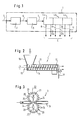
- the exemplary embodiment of a cutting device 2 shown in FIG. 2 consists of a screw conveyor 13 which, through a drive shaft 14 and a drive 15, gently presses the meat fed in via a funnel 16 through a gate knife 17 on the discharge side.
- Gate knives are known in principle and produce pieces of meat with a precise geometric dimension, which are then cut to a desired length by a downstream rotating knife 18.
- the meat is divided into flat pieces of defined thickness in the cutting device 2.
- FIG. 3 schematically shows an exemplary embodiment of a disintegrating device 3 in which the flat pieces of a certain thickness are mechanically disintegrated in accordance with a precisely specified pattern.
- the unlocking device 3 comprises a transport device 19, which is shown in a channel-like manner for the sake of simplicity.
- Toothed disks 22 are arranged axially next to one another on the drive shafts 20, so that opening rollers 23 are formed which act on the flat pieces of a certain thickness from both sides.
- the toothed disks 22 are equipped in their circumferential area with puncturing or incision teeth 24 which are shaped in accordance with the unlocking pattern already mentioned and are arranged with respect to one another.
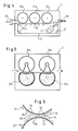
- the separating device 4 shown schematically in FIG. 4 is a three-stage sieve drum press belt arrangement.
- three sieve drums 25a, 25b and 25c are arranged at a certain distance one behind the other with axes parallel to one another.
- a press belt 26 is guided over rollers 27 in such a way that the flat pieces of meat mechanically disrupted in the opening device 3 are passed one after the other first under the sieve drum 25a and then under the sieve drums 25b and 25c.
- the working direction of the separating device shown in FIG. 4 is indicated by arrows 28.
- the press belt 26 is driven by a drive 29 or a plurality of drive press rolls. The drive of the sieve drums is not shown.
- the size of the perforation of the sieve drums, the length of the press nip between the press belt 26 and the associated sieve drum surface, the height of the press nip and the pressure on the flat pieces of meat are determined and set according to the respective requirements by tests for the respective type and consistency of meat in a known manner. While the harder meat components leave the separating device 4 on the output side via the press belt 26, the softer meat components are removed from the interior of the sieve drums in a manner known per se by scraping or conveying devices, not shown.
- Screen drums 30a and 30b are also used in the two-stage separating device 4 shown schematically in FIG. Instead of a press belt, the screen drums 30a and 30b are opposed by pressure rollers 31a and 31b, which are made of an elastically deformable material, such as special rubber or plastic, and are designed as a hollow pressure body. Devices, not shown, act on the inside of the hollow pressure body with a pressure medium, such as air or liquid.
- a pressure medium such as air or liquid.
- the arrangement is such that the pressure rollers 31a and 31b enclose the screening drums 30a and 30b over a certain angle of their circumference.
- the angle is chosen according to the meat to be processed and the dimensions of the flat pieces and is preferably between 30 ° and 50 °.
- the pressure in turn can be controlled via the pressure of the pressure medium.
- the embodiment variant according to FIG. 5 works in the same way as the embodiment according to FIG. 4.
- FIG. 1 A detail of a further embodiment is shown in FIG.
- the working gap through which the flat meat pieces of a certain thickness are mechanically disrupted in the opening device 3 is formed by the gap between two toothed drums 32, of which only a part of the circumference is shown schematically.
- These toothed drums 32 have rounded teeth 33 in the area of their circumference. These teeth have rounded tooth tips 34.
- a tooth base 35 which is designed in accordance with the shape of the opposite tooth tips 34 is provided and has openings or slots 36 through which a connection from the Toothed drum peripheral surface is made to the interior.
- the toothed drums 32 are thus sieve drums with a toothed peripheral surface.
- the toothed drums 32 of each pair of toothed drums are arranged at a distance from one another to form the working gap, as can be seen from FIG. They are driven synchronously, in such a way that the tooth tip 34 of a toothed drum is opposite the tooth base 35 of the adjacent toothed drum.
- a “wave-shaped” working gap is formed, as can be clearly seen from FIG. 6.
- the soft components of the meat are pressed out into the interior of the toothed drums via the openings or slots 36 and then withdrawn from them in a known manner.
- the peculiarity of this arrangement is that the squeezing process takes place alternately, and thus pulsates to one side and the other, while the meat is moved through the undulating working gap. Such an arrangement results in a particularly good degree of separation with gentle treatment.
Landscapes
- Life Sciences & Earth Sciences (AREA)
- Engineering & Computer Science (AREA)
- Wood Science & Technology (AREA)
- Zoology (AREA)
- Food Science & Technology (AREA)
- Meat, Egg Or Seafood Products (AREA)
- Processing Of Meat And Fish (AREA)
- Crushing And Pulverization Processes (AREA)
Description
Die vorliegende Erfindung betrifft ein Verfahren und eine Vorrichtung zum Aufbereiten von Fleisch, wie aus dem Dokument DE-A-1507972 bekannt, wobei das Fleisch in einem ersten Schritt zerkleinert und in einem anschließenden weiteren Schritt einem ein- oder mehrstufigen Trennvorgang unterzogen wird.The present invention relates to a method and an apparatus for processing meat, as known from document DE-A-1507972, the meat being comminuted in a first step and subjected to a one- or multi-stage separation process in a subsequent further step.
Zur Herstellung von Fleischprodukten ist es erforderlich, das Fleisch aufzubereiten. Diese Aufbereitung besteht darin, daß das eigentliche Muskelgewebe von Knochen, Bändern, Knorpeln, Faszien, Bindegewebe, Fett und dergleichen getrennt wird. Das auf diese Weise gewonnene, "reine" Muskelgewebe kann dann zu dem gewünschten Fleischprodukt weiterverarbeitet werden, während die abgetrennten Bestandteile in davon getrennten Arbeitsgängen für andere Zwecke aufbereitet, weiterverarbeitet oder entsorgt werden.To produce meat products, it is necessary to prepare the meat. This preparation consists in separating the actual muscle tissue from bones, ligaments, cartilages, fascia, connective tissue, fat and the like. The "pure" muscle tissue obtained in this way can then be processed further to the desired meat product, while the separated components are processed, processed or disposed of in separate work steps for other purposes.
Das Trennen des Muskelgewebes von den oben genannten Bestandteilen bereitet in der Praxis erhebliche Probleme. Zwar sind die festen Bestandteile, wie beispielsweise die Knochen oder Knorpel noch relativ einfach und vollständig von den weichen Bestandteilen, wie dem Muskelgewebe und dem Fett zu trennen. Erheblich schwieriger ist es jedoch bereits, wenn relativ weiche Bestandteile, wie beispielsweise Fett, weiches Bindegewebe oder dergleichen Bestandteile von weichem Muskelgewebe getrennt werden sollen. Selbst unter Einsatz moderner Verfahrensweisen und Vorrichtungen läßt sich hierbei nur ein relativ unbefriedigender Abtrennungsgrad erzielen.The separation of the muscle tissue from the above-mentioned components causes considerable problems in practice. The solid components, such as the bones or cartilage, can still be separated relatively easily and completely from the soft components, such as the muscle tissue and the fat. However, it is already considerably more difficult if relatively soft components, such as fat, soft connective tissue or similar components are to be separated from soft muscle tissue. Even using modern procedures and devices, only a relatively unsatisfactory degree of separation can be achieved.
Eine gängige, bekannte Verfahrensweise besteht beispielsweise darin, in einem ersten Schritt eine Zerkleinerung des Fleisches einschließlich Knochen bzw. Knochenteile und anderer Bestandteile in einer Art Fleischwolf vorzunehmen, und das auf diese Weise zerkleinerte Gut zwischen einem Preßband und einer Siebtrommel hindurchzuführen (vgl. beispielsweise DE-OS 38 44 301 oder DE-AS 17 82 800). Bei diesem Vorgang entsteht durch die Zerkleinerung im Fleischwolf eine durchmischte Fleischmasse, deren weiche Bestandteile dann in einer Art passiervorgang über das Preßband durch die Perforation der Trommel hindurchgequetscht werden. Auf diese Weise können zwar Bestandteile weicher und härterer Konsistenz voneinander getrennt werden. Ein Separieren weicher Bestandteile voneinander, wie beispielsweise ein Auftrennen in Muskelgewebe, weichem Bindegewebe und Fett ist jedoch mit dieser Verfahrensweise nicht oder nur sehr unzulänglich möglich.A common, known procedure consists, for example, in a first step of comminuting the meat, including bones or bone parts and other components, in a type of meat grinder, and passing the comminuted product in this way between a press belt and a sieve drum (see, for example, DE -OS 38 44 301 or DE-AS 17 82 800). In this process, the comminution in the meat grinder creates a mixed meat mass, the soft components of which are then squeezed through the perforation of the drum in a kind of passing process over the press belt. In this way, components of softer and harder consistency can be separated. Separating soft components from one another, such as, for example, separating them into muscle tissue, soft connective tissue and fat, is not possible or is possible only inadequately with this procedure.
Um die Qualität des Trennvorganges zu verbessern, ist auch bereits vorgeschlagen worden, den an den Zerkleinerungsschritt anschließenden Verfahrensschritt der Auftrennung in der Weise mehrstufig auszugestalten, daß mehrere, jeweils mit einer abnehmenden Perforationsgröße ausgestattete Siebtrommel-Preßband-Einheiten hintereinander geschaltet werden (vgl. beispielsweise DE-OS 15 07 972). Ein derartiges mehrstufiges Durchpassieren oder Siebpressen erbringt zwar graduelle Verbesserungen. Eine zufriedenstellende Auftrennung bzw. Separierung in Muskelgewebe, Fettgewebe, Bindegewebe und harte Bindegewebs-Knorpel- und Knochenanteile ist jedoch auch auf diese Weise nicht möglich. Auch wird im vorgeschalteten Zerkleinerungsschritt und insbesondere beim anschließenden Trennschritt das Muskelgewebe aufgrund der Quetschvorgänge, hohen Drücken, Scherkräften und anderen mechanischen Belastungen ausgesetzt, die die Struktur des Muskelgewebes weitgehend zerstören, so daß kein hochwertiges Ergebnis erzielt werden kann.In order to improve the quality of the separation process, it has also already been proposed to design the separation step following the comminution step in such a way that several sieve drum press belt units, each with a decreasing perforation size, are connected in series (see, for example, DE -OS 15 07 972). Such a multi-stage pass-through or screen pressing does bring about gradual improvements. However, a satisfactory separation or separation into muscle tissue, fat tissue, connective tissue and hard connective tissue-cartilage and bone parts is also not possible in this way. The muscle tissue is also caused in the upstream comminution step and in particular in the subsequent separation step the squeezing processes, high pressures, shear forces and other mechanical loads, which largely destroy the structure of the muscle tissue, so that no high-quality result can be achieved.
Aufgabe der vorliegenden Erfindung ist es daher, eine vollkommen neuartige Verfahrensweise und Vorrichtung zur Verfügung zu stellen, die bei möglichst schonender Behandlung des Fleisches einen sehr hohen Abtrennungsgrad erzielt.It is therefore an object of the present invention to provide a completely novel method and device which achieves a very high degree of separation while treating the meat as gently as possible.
Diese Aufgabe wird erfindungsgemäß dadurch gelöst, daß das Zerkleinern im ersten Schritt durch ein Aufteilen des Fleisches in flächige Stücke bestimmter Dicke erfolgt, und daß in einem zwischen dem ersten Schritt und dem ein- oder mehrstufigen Trennvorgang liegenden zweiten Schritt ein auf diesen Trennvorgang abgestimmtes Aufschließen der flächigen Stücke vorgenommen wird, so daß ihre Struktur gezielt aufgebrochen wird.This object is achieved in that the chopping takes place in the first step by dividing the meat into flat pieces of a certain thickness, and in a second step between the first step and the single-stage or multi-stage separation process, a disintegration tailored to this separation process flat pieces is made so that their structure is deliberately broken.
Der Vorgang des "mechanischen Aufschließens" ist in der Fleischverarbeitung seit langem bekannt. Unter mechanischem "Aufschließen" wird eine mechanische Einwirkung auf das Fleisch verstanden, die die Struktur des Fleisches gezielt aufbricht. Auf diese Weise kann beispielsweise die Absorption von Konservierungsmitteln und/oder Würzstoffen (Fökellake) verbessert oder auch aufgrund der Festigkeitsreduzierung die "Zartheit" des Fleisches erhöht werden.The process of "mechanical disintegration" has long been known in meat processing. Mechanical "unlocking" is understood to mean a mechanical action on the meat which specifically breaks up the structure of the meat. In this way it is possible, for example, to improve the absorption of preservatives and / or seasonings (feces) or to increase the "tenderness" of the meat due to the reduction in strength.
In der Praxis wird das mechanische Aufschließen von Fleisch unter anderem durch Walzensysteme erzielt, die Einschnitte, Einstiche, Einkerbungen oder dergleichen bis in eine vorbestimmte Tiefe in das Fleisch einbringen (vgl. beispielsweise DE-OS 35 09 735). Neben der bereits erwähnten verbesserten Absorption für Konservierungsmittel wird bei dieser bekannten Verfahrensweise auch eine verbesserte Bindung von mehreren Fleischstücken für die nachfolgende Verarbeitung bewirkt.In practice, mechanical pulping of meat is achieved, inter alia, by roller systems which make incisions, punctures, notches or the like into the meat to a predetermined depth (cf., for example, DE-OS 35 09 735). In addition to the already The above-mentioned improved absorption for preservatives also results in an improved binding of several pieces of meat for the subsequent processing in this known procedure.
Erfindungsgemäß wird nun anstelle des üblichen Zerquetschens im ersten Schritt ein schonendes Aufteilen des Fleisches in flächige Stücke, wie Scheiben, Streifen oder Schnitzel vorgenommen. Erfindungsgemäß wird dann in einem auf dieses Aufteilen folgenden zweiten Schritt das in flächigen Stücken vorliegende Gut vor dem eigentlichen Trennvorgang gezielt in der Weise mechanisch aufgeschlossen, daß das "Aufschließmuster" genau auf das im daran anschließenden Trennvorgang eingesetzte "Muster" abgestimmt ist. Mit anderen Worten: Wird der Trennvorgang über eine Siebtrommel- oder Siebbandanordnung realisiert, ist das Einschneide-, Einkerb- oder Einstichmuster des mechanischen Aufschließvorganges genau auf das Perforationsmuster der Siebtrommel- oder Siebbandanordnung abgestimmt. Die Einschnitte oder Einstiche des mechanischen Aufschließvorgangs werden dabei so gelegt, daß ein Schnittraster entsteht, über das im anschließenden Trennvorgang jeder innerhalb der Schnitte liegende Fleischabschnitt schonend ausgepreßt werden kann. Dabei spielt die Art und die Konsistenz des Fleisches eine wesentliche Rolle. So kann beispielsweise im Falle eines Trennvorganges über eine Preßband-Siebtrommelanordnung bei gleichem Schnittmuster und gleichem Druck zartes Fleisch über eine kleinere Perforation ausgepreßt werden als weniger zartes oder zähes Fleisch, für das in jedem Falle eine größere Perforation erforderlich ist.According to the invention, instead of the usual crushing in the first step, the meat is carefully divided into flat pieces, such as slices, strips or cutlets. According to the invention, in a second step following this division, the material present in flat pieces is then mechanically disrupted prior to the actual separation process in such a way that the “disintegration pattern” is precisely matched to the “pattern” used in the subsequent separation process. In other words: If the separation process is carried out using a sieve drum or sieve belt arrangement, the incision, notch or puncture pattern of the mechanical unlocking process is precisely matched to the perforation pattern of the sieve drum or sieve belt arrangement. The incisions or punctures of the mechanical unlocking process are placed in such a way that a cutting grid is created, by means of which each meat section lying within the cuts can be gently squeezed out in the subsequent cutting process. The type and consistency of the meat play an important role. For example, in the case of a separation process using a press belt sieve drum arrangement with the same cutting pattern and the same pressure, tender meat can be pressed out via a smaller perforation than less tender or tough meat, for which a larger perforation is required in any case.
Versuche haben nun gezeigt, daß in dieser Weise abgestimmt aufgeschlossene flächige Fleischstücke sich im Trennvorgang erheblich wirkungsvoller und schonender aufbereiten lassen als mit bekannten Verfahrensweisen und Vorrichtungen. So wird bereits bei einem einstufigen Trennvorgang ein erheblich besserer Abtrennungsgrad erzielt als bei vergleichbaren Verfahrensweisen der bekannten Art. Ist der Trennvorgang dagegen mehrstufig ausgebildet, kann ein bisher nicht erreichbarer Abtrennungsgrad bei höchster Qualität erzielt werden.Experiments have now shown that in this way, broken open flat meat pieces are considerably more effective and gentle in the separation process have them processed than with known procedures and devices. In a single-stage separation process, a considerably better degree of separation is achieved than in comparable procedures of the known type. On the other hand, if the separation process is multi-stage, a previously unachievable degree of separation with the highest quality can be achieved.
Maßgeblich für den im Trennvorgang erzielbaren Abtrennungsgrad ist erfindungsgemäß die Abstimmung der Dicke der flächigen Fleischstücke auf den mechanischen Aufschließvorgang. Je nach Fleischart oder Konsistenz kann die optimale Dicke der flächigen Stücke durch Versuche festgelegt werden.Decisive for the degree of separation achievable in the separation process is, according to the invention, the matching of the thickness of the flat pieces of meat to the mechanical digestion process. Depending on the type of meat or consistency, the optimal thickness of the flat pieces can be determined by experiments.
Grundsätzlich ist es möglich, den Trennvorgang über beliebig viele Stufen vorzunehmen. Besonders vorteilhafte Ergebnisse werden jedoch mit einem Trennvorgang erzielt, der sich über zwei oder drei Stufen erstreckt. In einem solchen Falle steht dem erreichten Abtrennungsgrad ein wirtschaftlich sinnvoller apparativer Aufwand gegenüber.Basically, it is possible to carry out the separation process over any number of stages. However, particularly advantageous results are achieved with a separation process that extends over two or three stages. In such a case, the degree of separation achieved is offset by an economically sensible expenditure on equipment.
Im Falle eines zwei- oder dreistufigen Trennvorganges wird in der ersten Stufe aufgrund des vorgeschalteten, abgestimmten mechanischen Aufschließvorganges bei flächigen Stücken optimaler Dicke bereits die Hauptmenge von Muskelgewebe abgetrennt, so daß lediglich weiches Bindegewebe, Fettgewebe, Sehnen, Faszien, Bänder, Knochen und Knorpel verbleiben. In der zweiten Stufe erfolgt dann ein Abt rennen von Restmuskelgewebe, Fettgewebe und weichem Bindegewebe, wobei härteres Bindegewebe, Faszien, Bänder, Knochen und Knorpel verbleiben. Ist eine dritte Stufe nachgeschaltet, erfolgt in dieser ein weiteres Abtrennen von Restmuskelgewebe, Pestfett und weichem Restbindegewebe, so daß lediglich Sehnen, Knorpel und Knochen verbleiben. Im Falle des Einsatzes von bekannten Preßband-Siebtrommeleinheiten für die einzelnen Stufen ist es vorteilhaft, die auf den vorgeschalteten mechanischen Aufschließvorgang abgestimmten Perforationsöffnungen in jeder Stufe hinsichtlich ihres Querschnittes zu reduzieren.In the case of a two- or three-stage separation process, the majority of muscle tissue is already separated in the first stage due to the upstream, coordinated mechanical unlocking process for flat pieces of optimal thickness, so that only soft connective tissue, fat tissue, tendons, fasciae, ligaments, bones and cartilage remain . In the second stage, residual muscle tissue, fat tissue and soft connective tissue are separated, leaving harder connective tissue, fasciae, ligaments, bones and cartilage. If a third stage is added, this is a further separation of residual muscle tissue, plague fat and soft Residual connective tissue so that only tendons, cartilage and bone remain. If known press belt sieve drum units are used for the individual stages, it is advantageous to reduce the cross section of the perforation openings in each stage, which are matched to the upstream mechanical unlocking process.
Einen weiteren Parameter stellt der auf das zu verarbeitende Gut in jeder Stufe aufgebrachte Preßdruck dar. So haben Versuche gezeigt, daß es vorteilhaft ist, den Preßdruck von Stufe zu Stufe zu erhöhen.Another parameter is the pressing pressure applied to the material to be processed in each stage. Tests have shown that it is advantageous to increase the pressing pressure from stage to stage.
Durch das mechanische Aufschließen wird es ermöglicht, im Trennvorgang auf das Fleisch nicht über einen längeren Zeitraum einen großflächigen Druck, sondern über einen kürzeren Zeitraum einen kleinflächigeren Druck auszuüben. Im Falle des Einsatzes von Walzen oder Preßband-Siebtrommelanordnungen ist es darüber hinaus vorteilhaft, nicht mit einem sogenannten Nullspalt, sondern mit einem gewissen Abstand zwischen den druckausübenden Flächen zu arbeiten. Im Falle des Einsatzes eines Preßbandes kann dies mit einer niedrigen Preßbandspannung erreicht werden.The mechanical disintegration makes it possible not to exert a large area pressure on the meat over a longer period of time, but rather to exert a smaller area pressure over a shorter period. If rolls or press belt sieve drum arrangements are used, it is also advantageous not to work with a so-called zero gap, but with a certain distance between the pressure-exerting surfaces. If a press belt is used, this can be achieved with a low press belt tension.
Bei einem mehrstufigen Trennvorgang wiederum ist es zweckmäßig, zumindest den Abstand der druckausübenden Flächen in der ersten Stufe einstellbar und steuerbar auszubilden. Die optimalen Bedingungen können je nach Fleischart und Fleischkonsistenz durch Versuche festgelegt werden.In the case of a multi-stage separation process, in turn, it is expedient to make the distance between the pressure-exerting surfaces adjustable and controllable in the first stage. Depending on the type of meat and meat consistency, the optimal conditions can be determined by experiments.
Der Abtrennungsgrad kann gemäß einer vorteilhaften Weiterbildung der Erfindung noch durch den Einsatz einer Zwischenstufe zwischen zwei Stufen verbessert werden. So ist es möglich, als Zwischenstufe beispielsweise eine Flotationsstufe einzusetzen, in der eine Auftrennung durch Flotation in Wasser oder in lebensmittelrechtlich zugelassenen Lösungen von Salzen und/oder Genußsäuren erfolgt.According to an advantageous development of the invention, the degree of separation can be improved by using an intermediate stage between two stages. So it is possible, for example, to use a flotation stage as an intermediate stage, in which a separation by flotation in water or in food-approved solutions of salts and / or edible acids takes place.
Für bestimmte Anwendungsgebiete können als Zwischenstufe zum Feinseparieren gegebenenfalls auch Adhäsionstrennverfahren, Rütteltischtrennverfahren, Zentrifugaltrennverfahren oder gegebenenfalls auch Windsichtungsverfahren unter Ausnutzung des unterschiedlichen spezifischen Gewichtes von Fett und Muskelgewebe eingesetzt werden. Darüber hinaus ist es möglich, als Zwischenstufe elektronisch gesteuerte, optische Feinseparierverfahren einzusetzen, sofern eine Auftrennung nach Farbunterschieden möglich ist.For certain areas of application, an intermediate stage for fine separation can also be used, if appropriate, for adhesion separation processes, vibrating table separation processes, centrifugal separation processes or, if appropriate, also air separation processes using the different specific weights of fat and muscle tissue. In addition, it is possible to use electronically controlled, optical fine separation processes as an intermediate stage, provided that a separation according to color differences is possible.
Eine vorteilhafte Vorrichtung zur Durchführung des erfindungsgemäßen Verfahrens umfaßt eine Schneideinrichtung zum Aufteilen des Fleisches in flächige Stücke bestimmter Dicke, eine an diese anschließende mechanische Aufschließeinrichtung die die Struktur der flächigen Stücke gezielt aufbricht und eine sich an diese Aufschließeinrichtung anschließende und darauf abgestimmte ein- oder mehrstufige Trenneinrichtung.An advantageous device for carrying out the method according to the invention comprises a cutting device for dividing the meat into flat pieces of a certain thickness, a mechanical disintegrating device which adjoins the structure of the flat pieces in a targeted manner and a single or multi-stage separating device which adjoins this and is matched to this .
Grundsätzlich ist es möglich, für den Aufbau der Schneideinrichtung, der Aufschließeinrichtung und der Trenneinrichtung bekannte Elemente einzusetzen. Wesentlich ist allerdings, daß diese bekannten Elemente in aufeinander aufbauender und aufeinander abgestimmter und abstimmbarer Arbeitsweise derart ausgestaltet sind, daß eine Arbeitsweise gemäß dem erfindungsgemäßen Verfahren realisiert werden kann. Hinsichtlich der Abstimmung ist der Aufbau der Aufschließeinrichtung in bezug auf die Trenneinrichtung von besonderer Bedeutung, wie dies bereits im Zusammenhang mit dem erfindungsgemäßen Verfahren im einzelnen erläutert wurde.In principle, it is possible to use known elements for the construction of the cutting device, the disintegrating device and the separating device. It is essential, however, that these known elements are designed in a manner that builds on one another and is coordinated with one another in such a way that a method of operation can be implemented in accordance with the method according to the invention. With regard to the coordination, the structure of the unlocking device is related to the Separating device of particular importance, as has already been explained in detail in connection with the method according to the invention.
Grundsätzlich können die Schneideinrichtung, die Aufschließeinrichtung und die Trenneinrichtung voneinander getrennt sein. Vorteilhaft ist es jedoch, wenn die Schneideinrichtung, die Aufschließeinrichtung und die Trenneinrichtung hintereinander geschaltet zu einer Maschineneinheit zusammengefaßt sind.In principle, the cutting device, the disintegrating device and the separating device can be separated from one another. However, it is advantageous if the cutting device, the disintegrating device and the separating device are combined in series to form a machine unit.
Die Schneideinrichtung kann in verschiedenster Weise konstruiert sein. Wesentlich ist, daß das Fleisch unter möglichst schonender Behandlung in flächige Stücke vorbestimmter Dicke aufgeteilt werden kann. Vorteilhaft ist es, als Schneideinrichtung einen Schneckenförderer mit ausgangsseitig vorgeschaltetem rotierendem Messer vorzusehen. Je nach Einsatzweck kann diesem rotierenden Messer ein sogenanntes Gattermesser vorgeschaltet sein.The cutting device can be constructed in various ways. It is essential that the meat can be divided into flat pieces of predetermined thickness with the least possible care. It is advantageous to provide a screw conveyor with a rotating knife connected upstream on the output side as the cutting device. Depending on the application, this rotating knife can be preceded by a so-called gate knife.
Das rotierende Messer kann als Flügel- oder Scheibenmesser ausgestaltet sein. Der Antrieb kann gemäß einem bevorzugten Ausführungsbeispiel durch die Welle des Schneckenförderers erfolgen, die in einem solchen Fall als Hohlwelle ausgestaltet ist.The rotating knife can be designed as a wing or disc knife. According to a preferred exemplary embodiment, the drive can take place through the shaft of the screw conveyor, which in such a case is designed as a hollow shaft.
Die Schneideinrichtung kann auch als auf einer horizontalen Achse geführte und mit einem Transportband zusammenarbeitende Scheibenmesseranordnung ausgestaltet sein.The cutting device can also be designed as a disk knife arrangement guided on a horizontal axis and working together with a conveyor belt.
In speziellen Fällen kann es auch möglich sein, das Fleisch in gefrorenem Zustand zu schneiden. In solchen Fällen ist es vorteilhaft, wenn die Schneideinrichtung als Gefrierfleischblockschneider ausgebildet ist. Ein derartiger Gefrierfleischblockschneider kann beispielsweise als Säge- oder als Fräseinrichtung arbeiten.In special cases it may also be possible to cut the meat in a frozen state. In such cases, it is advantageous if the cutting device as Frozen meat block cutter is trained. Such a frozen meat block cutter can work, for example, as a sawing or milling device.
Die mechanische Aufschließeinrichtung kann ebenfalls in verschiedenster Weise gestaltet sein. Vorteilhaft ist es, wenn die mechanische Aufschließeinrichtung einander gegenüberliegende und gegenläufig zueinander rotierende Aufschließwalzen aufweist.The mechanical unlocking device can also be designed in a wide variety of ways. It is advantageous if the mechanical disintegration device has disintegration rollers which are opposite one another and rotate in opposite directions to one another.
Das Hindurchbewegen der flächigen Fleischstücke zwischen den Aufschließwalzen kann in verschiedenster Weise erfolgen. In den meisten Fällen reicht es aus, für eine Zu- und Abfuhr Sorge zu tragen, da die flächigen Fleischstücke durch die Aufschließwalzen selbst durch die Aufschließeinrichtung hindurchgefördert werden. Falls dies nicht der Fall sein sollte, ist es vorteilhaft, eine spezielle Transporteinrichtung vorzusehen. Für den Fall, daß die Achsen der Aufschließwalzen in einer horizontalen Ebene liegen, reicht in aller Regel die Schwerkraft aus, um die flächigen Fleischstücke in den Einzugsbereich der Aufschließwalzen zu bewegen.The flat pieces of meat can be moved through between the digestion rollers in a variety of ways. In most cases it is sufficient to take care of a supply and removal, since the flat pieces of meat are conveyed through the pulping rollers themselves through the pulping device. If this should not be the case, it is advantageous to provide a special transport device. In the event that the axes of the pulping rollers lie in a horizontal plane, gravity is generally sufficient to move the flat pieces of meat into the feed area of the pulping rollers.
Im Bedarfsfalle ist es möglich, lediglich eine Aufschließwalze vorzusehen, und diese mit einem Förderband zusammenarbeiten zu lassen, welches den erforderlichen Gegendruck erzeugt.If necessary, it is possible to provide only one digestion roller and to have it work together with a conveyor belt, which generates the required counter pressure.
Um eine optimale Anpassung an das jeweils aufzuschließende Fleisch zu ermöglichen, ist es vorteilhaft, die Aufschließwalzen verstellbar bzw. zusammenstellbar auszubilden. Gemäß einem bevorzugten Ausführungsbeispiel bestehen die Aufschließwalzen aus Antriebswellen, auf denen axial nebeneinander eine Anzahl von Zahnscheiben angeordnet sind. Bei einer derartigen Anordnung ist es vorteilhaft, die Antriebswellen abstandsverstellbar nebeneinander anzuordnen, um den optimalen Arbeitsspalt zwischen den Aufschließwalzen durch Versuche bestimmen zu können. Aufgrund der Ausbildung der Aufschließwalzen aus einer Anzahl von Zahnscheiben ist es möglich, dem jeweiligen Anwendungszweck entsprechend Zahnscheibensätze aus verschiedenen Zahnscheiben zusammenzustellen.In order to enable optimal adaptation to the meat to be broken down, it is advantageous to design the breakup rollers so that they can be adjusted or put together. According to a preferred embodiment, the unlocking rollers consist of drive shafts on which a number of toothed disks are located axially next to one another are arranged. With such an arrangement, it is advantageous to arrange the drive shafts next to one another with adjustable spacing in order to be able to determine the optimum working gap between the digestion rollers by experiments. Due to the formation of the disintegrating rollers from a number of toothed disks, it is possible to assemble sets of toothed disks from different toothed disks according to the respective application.
Aus Zahnscheiben zusammengestellte Aufschließwalzen können darüber hinaus einfach gereinigt werden. Zu diesem Zweck werden die Zahnscheiben von den Antriebswellen abgezogen und in einem separaten Arbeitsgang einzeln gereinigt.Digestion rollers composed of toothed disks can also be easily cleaned. For this purpose, the toothed lock washers are removed from the drive shafts and cleaned individually in a separate operation.
Diese Zahnscheiben besitzen an ihrem Umfang Einstich- oder Einschnittzähne, die gemäß einem vorgegebenen Aufschließmuster geformt und zueinander angeordnet sind.These toothed disks have puncture or incision teeth on their circumference, which are shaped according to a predetermined unlocking pattern and arranged with respect to one another.
Die Trenneinrichtung kann ebenfalls in verschiedenster Weise gestaltet sein. Sie kann ein- oder mehrstufig ausgebildet sein, wobei die Stufen gleichartig oder auch unterschiedlich ausgebildet sein können.The separating device can also be designed in a wide variety of ways. It can be of one or more stages, the stages being of the same or different design.
Ein besonders gutes Verhältnis zwischen Abscheidungsgrad und apparativem Aufwand ergibt sich bei einer zwei- oder dreistufigen Ausbildung der Trenneinrichtung.A particularly good relationship between the degree of separation and the expenditure on equipment results from a two- or three-stage design of the separating device.
Die einzelnen Stufen der Trenneinrichtung können als Preßband-Siebtrommeleinheit, Siebband-Preßtrommeleinheit, Siebtrommel-Siebtrommeleinheit oder Siebtrommel-Druckwalzeneinheit ausgestaltet sein. Darüber hinaus ist es möglich, die einzelnen Stufen der Trenneinrichtung als Drucktrommel-Siebtrommeleinheit auszugestalten. In einem solchen Fall läuft im Innenraum der Druck- oder Siebtrommel achsversetzt eine rotierende Sieb- oder Drucktrommel kleineren Durchmessers. Durch den Versatz der beiden Achsen wird zwischen der Innenfläche der äußeren Trommel und der Außenfläche der inneren Trommel ein Arbeitsspalt gebildet, der sich stetig verringert und im Anschluß daran wieder stetig erweitert.The individual stages of the separating device can be designed as a press belt sieve drum unit, sieve belt press drum unit, sieve drum sieve drum unit or sieve drum pressure roller unit. In addition, it is possible to design the individual stages of the separating device as a printing drum / sieve drum unit. In such a case, the interior runs the printing or screening drum has a rotating screen or printing drum with a smaller diameter. Due to the offset of the two axes, a working gap is formed between the inner surface of the outer drum and the outer surface of the inner drum, which gap is continuously reduced and subsequently expanded again.
Im Falle einer Siebtrommel-Druckwalzeneinheit liegt der Siebtrommel jeweils achsparallel eine Druckwalze gegenüber. Diese Druckwalze kann aus elastischem Material bestehen oder auch elastisch deformierbar ausgebildet sein.In the case of a screen drum pressure roller unit, the screen drum is opposed to a pressure roller parallel to the axis. This pressure roller can consist of elastic material or can also be designed to be elastically deformable.
Im Falle einer elastischen deformierbaren Ausbildung der Druckwalze ist es vorteilhaft, diese als hohlen Druckkörper zu gestalten, der auf seiner Innenseite mit einem Druckmedium beaufschlagbar ist. Bei einer derartigen Ausgestaltung erfährt die Druckwalze in ihrem der Siebtrommel gegenüberliegenden Druckbereich eine Deformation, die entsprechend der gewünschten Druckfläche sich über einen bestimmten Winkelbereich der Siebtrommel erstrecken kann. Vorteilhaft ist ein Winkelbeieich von etwa 30° bis 50°.In the case of an elastic, deformable design of the pressure roller, it is advantageous to design it as a hollow pressure body which can be acted upon by a pressure medium on its inside. With such a configuration, the printing roller undergoes a deformation in its printing area opposite the screen drum, which deformation can extend over a certain angular range of the screen drum in accordance with the desired printing area. An angular range of approximately 30 ° to 50 ° is advantageous.
Das in den Innenraum der Siebtrommel gepreßte Fleisch kann grundsätzlich in jeder beliebigen Weise abgezogen werden. Hierzu eignen sich beispielsweise bekannte Schab- und Ausfördereinrichtungen. Gemaß seiner vorteilhaften Weiterbildung der Erfindung kann ein Abziehen des Fleisches von der Innenseite dar Siebtrommel auch über eine Saugeinrichtung erfolgen, die im Innenraum der Trommel im Bereich der Überdeckung durch die Druckwalzen angeordnet ist. Diese Saugeinrichtung kann in verschiedenster Weise ausgebildet sein. Vorteilhaft ist die Ausbildung als Saughaube, die einen bestimmten Sektor des Innenraumes abdeckt.The meat pressed into the interior of the sieve drum can in principle be removed in any manner. Known scraping and discharge devices are suitable for this purpose, for example. According to its advantageous development of the invention, the meat can also be removed from the inside of the sieve drum by means of a suction device which is arranged in the interior of the drum in the region of the overlap by the pressure rollers. This suction device can be designed in various ways. The training as a suction hood, which covers a certain sector of the interior, is advantageous.
Die Trenneinrichtung kann auch als Zahntrommelanordnung ausgestaltet sein. In einem solchen Fall liegen zwei Zahntrommeln achsparallel zur Bildung eines Zahntrommelpaares gegenüber. Die Verzahnung der Zahntrommeln kann je nach Einsatzzweck gerad-, schräg- oder sogar pfeilverzahnt sein.The separating device can also be designed as a toothed drum arrangement. In such a case, two toothed drums lie opposite each other parallel to the formation of a pair of toothed drums. The toothing of the toothed drums can be straight, helical or even arrow-toothed, depending on the application.
Die Verzahnung der Zahntrommeln kann in verschiedener Weise gestaltet sein. So können die Zähne einstückig mit der Zahntrommel ausgebildet sein. Vorteilhaft ist es auch, die Zähne der Zahntrommeln von Zahnleisten zu bilden, die auf den Trommelkörper aufgesetzt sind.The toothing of the toothed drums can be designed in different ways. The teeth can thus be formed in one piece with the toothed drum. It is also advantageous to form the teeth of the toothed drums of toothed racks which are placed on the drum body.
Wesentlich ist jedoch in all den geschilderten Fällen, daß im Zahngrund zwischen zwei Zähnen jeweils Öffnungen oder Schlitze vorgesehen sind, die mit dem Trommelinnenraum in Verbindung stehen. Insofern stellen derartige Zahntrommelanordnungen letztlich eine Siebtrommelanordnung mit speziell, d.h. zahnartig ausgestalteter Umfangfläche dar.However, it is essential in all the cases described that openings or slots are provided in the tooth base between two teeth, which are connected to the interior of the drum. In this respect, such toothed drum arrangements ultimately constitute a sieve drum arrangement with special, i.e. tooth-like circumferential surface.
Grundsätzlich können die Öffnungen oder Schlitze in verschiedenster Weise ausgestaltet sein. Um einen möglichst reibungsfreien Durchtritt des Fleisches durch die Öffnungen oder Schlitze zu erreichen, ist es vorteilhaft, die Öffnungen oder Schlitze zum Trommelinnenraum hin erweitert auszubilden. Zweckmäßig ist es, die Erweiterung im wesentlichen konisch zu gestalten.Basically, the openings or slots can be designed in a wide variety of ways. In order to ensure that the meat passes through the openings or slots as smoothly as possible, it is advantageous to design the openings or slots to be extended toward the interior of the drum. It is advisable to make the extension essentially conical.
Besondere Bedeutung kommt auch der Gestaltung der Öffnungen oder Schlitze im Bereich des Überganges zur Trommelumfangsfläche zu. Dem jeweiligen Anwendungszweck entsprechend kann dieser Übergang beispielsweise gerundet oder auch nach Art einer Schneide ausgebildet sein.Of particular importance is the design of the openings or slots in the area of the transition to the drum peripheral surface. Depending on the respective application, this transition can be rounded, for example, or it can be designed like a cutting edge.
Im Falle einer Zahntrommelanordnung ist es zweckmäßig, die Zahntrommeln im Abstand voneinander anzuordnen, d.h. zwischen den einander zugewandten Zahnsystemen einen "wellenförmigen" Arbeitsspalt zu bilden.In the case of a toothed drum arrangement, it is expedient to arrange the toothed drums at a distance from one another, i.e. to form a "wavy" working gap between the facing tooth systems.
Vorteilhaft ist es, in einem solchen Fall die Zahntrommeln synchron jeweils derart anzutreiben, daß einer Zahnspitze der einen Trommel ein Zahngrund der benachbarten Trommel gegenüberliegt. Das Fleisch wird auf diese Weise jeweils von der Zahnspitze der einen Trommel durch die Öffnungen oder Schlitze im Zahngrund der jeweils benachbarten Trommel hindurchgequetscht, wodurch sich ein abwechselnd von verschiedenen Seiten auf die flächigen Fleischstücke einwirkender, quasi pulsierender Quetsch- oder Passiervorgang ergibt.In such a case, it is advantageous to drive the toothed drums synchronously in such a way that a tooth tip of one drum faces a tooth base of the adjacent drum. In this way, the meat is squeezed from the tooth tip of one drum through the openings or slots in the tooth base of the adjacent drum, resulting in a quasi-pulsating squeezing or passing process that acts on the flat pieces of meat alternately from different sides.
Im folgenden sind zur weiteren Erläuterung und zum besseren Verständnis der Erfindung Ausführungsbeispiele von nach dem erfindungsgemäßen Verfahren arbeitenden Vorrichtungen unter Bezugnahme auf die beigefügten Zeichnungen näher beschrieben.
Figur 1 zeigt anhand eines Blockschemas den grundsätzlichen Aufbau einerals Maschineneinheit 1 ausgebildeten Vorrichtung der erfindungsgemäßen Art, bestehend aus Schneideinrichtung 2,Aufschließeinrichtung 3 und Trenneinrichtung 4,Figur 2 zeigt schematisch eine Ausführungsform der Schneideinrichtung 2,Figur 3 zeigt schematisch eine Ausführungsform der Aufschließeinrichtung 3,Figur 4 zeigt schematisch eine erste Ausführungsform einer dreistufig ausgebildeten Trenneinrichtung 4,Figur 5 zeigt schematisch eine zweite Ausführungsform einer zweistufig ausgebildeten Trenneinrichtung 4, undFigur 6 zeigt schematisch ein Detail einer weiteren Ausführungsform einerTrenneinrichtung 4.
- FIG. 1 shows, using a block diagram, the basic structure of a device of the type according to the invention designed as a
machine unit 1, consisting of cuttingdevice 2, disintegratingdevice 3 and separatingdevice 4, - FIG. 2 schematically shows an embodiment of the
cutting device 2, - FIG. 3 schematically shows an embodiment of the unlocking
device 3, - FIG. 4 schematically shows a first embodiment of a three-
stage separating device 4, - Figure 5 shows schematically a second embodiment of a two-
stage separating device 4, and - FIG. 6 schematically shows a detail of a further embodiment of a
separating device 4.
Gemäß dem in Figur 1 dargestellten Blockschema wird das noch alle Bestandteile wie Muskelgewebe, Knochen, Bänder, Knorpel, Faszien, Bindegewebe, Fett und dergleichen aufweisende Fleisch über eine mit einem Pfeil 5 schematisch gekennzeichnete Transporteinrichtung in die Schneideinrichtung 2 eingespeist. In der Schneideinrichtung 2 wird das Fleisch einschließlich seiner Bestandteile in flächige Stücke aufgeteilt. Diese flächigen Stücke werden über eine mit einem Pfeil 6 schematisch gekennzeichnete Fördereinrichtung der Aufschließeinrichtung 3 zugeführt, in der sie nach einem genau vorgegebenen Muster mechanisch aufgeschlossen werden.According to the block diagram shown in FIG. 1, the meat which still has all the constituents, such as muscle tissue, bones, ligaments, cartilage, fascia, connective tissue, fat and the like, is obtained via meat with an
Die in dieser Weise mechanisch aufgeschlossenen Stücke gelangen dann über eine mit einem Pfeil 7 gekennzeichnete Fördereinrichtung in die Trenneinrichtung 4, welche aus mindestens einer Stufe 4a bestehen muß. Vorteilhaft ist es jedoch, wenn die Trenneinrichtung 4 aus zwei oder drei Stufen besteht, wie dies im Blockschema gemäß Figur 1 mit gestrichelten Linien dargestellt ist. Die zweite und die dritte Stufe sind im Blockschema gemäß Figur 1 mit 4b und 4c gekennzeichnet. In den Stufen 4a, 4b und 4c erfolgt der eingangs beschriebene Trennvorgang, der aufgrund des vorgeschalteten und genau abgestimmten mechanischen Aufschließvorganges in der Aufschließeinrichtung 3 erfindungsgemäß mit einem sehr hohen Abtrennungsgrad durchgeführt werden kann. Aufgrund dieser Ausgestaltung wird bereits in der ersten Stufe 4a der Trenneinrichtung 4 die Hauptmenge von Muskelgewebe abgetrennt, was im Blockschema gemäß Figur 1 mit einem Pfeil 8 symbolisiert ist. Beim Übergang in die zweite Stufe 4b verbleiben somit lediglich Rest-Muskelgewebe, weiches Bindegewebe, Fettgewebe, Sehnen, Faszien, Bänder, Knorpel und Knochen.The pieces mechanically disrupted in this way then reach the
In der zweiten Stufe 4b erfolgt dann ein Abtrennen von Restmuskelgewebe, Fettgewebe und weichem Bindegewebe, was im Blockschema gemäß Figur 1 mit einem Pfeil 9 angedeutet ist. Härteres Bindegewebe, Faszien, Bänder, Knochen und Knorpel verbleiben und werden in die dritte Stufe 4c weitergeleitet. In dieser dritten Stufe erfolgt ein weiteres Abtrennen von Restmuskelgewebe, Restfett und weichem Restbindegewebe, was mit einem Pfeil 10 symbolisch dargestellt wird. Die verbleibenden Sehnen, Knorpel und Knochen werden am Ende der dritten Stufe 4c abgeführt, was mit einem Pfeil 11 in Figur 1 angedeutet ist.In the second stage 4b, residual muscle tissue, fat tissue and soft connective tissue are then separated, which is indicated by an arrow 9 in the block diagram according to FIG. 1. Harder connective tissue, fascia, ligaments, bones and Cartilage remains and is passed on to the third stage 4c. In this third stage there is a further separation of residual muscle tissue, residual fat and soft residual connective tissue, which is symbolically represented by an
Wie eingangs bereits erwähnt, kann der Abtrennungsgrad im Bedarfsfalle gemäß einer vorteilhaften Weiterbildung der Erfindung noch durch den Einsatz von Zwischenstufen verbessert werden. Diese Zwischenstufen sind in Figur 1 nicht dargestellt. Sie dienen - wie bereits beschrieben - zum Feinseparieren. Die in diesen Zwischenstufen abgetrennten Bestandteile sind im Blockschema gemäß Figur 1 mit den Pfeilen 12a und 12b schematisch angedeutet.As already mentioned at the beginning, the degree of separation can, if necessary, be improved further by using intermediate stages in accordance with an advantageous development of the invention. These intermediate stages are not shown in FIG. 1. As already described, they are used for fine separation. The components separated in these intermediate stages are indicated schematically in the block diagram according to FIG. 1 with the
Das in Figur 2 dargestellte Ausführungsbeispiel einer Schneideinrichtung 2 besteht aus einem Schneckenförderer 13, der über eine Antriebswelle 14 und einen Antrieb 15 das über einen Trichter 16 eingespeiste Fleisch schonend abgabeseitig durch ein Gattermesser 17 hindurchpreßt. Gattermesser sind grundsätzlich bekannt und erzeugen Fleischstücke genauer geometrischer Abmessung, die dann durch ein nachgeschaltetes rotierendes Messer 18 auf eine gewünschte Länge geschnitten werden.The exemplary embodiment of a
Erfindungsgemäß erfolgt das Aufteilen des Fleisches in der Schneideinrichtung 2 in flächige Stücke definierter Dicke.According to the invention, the meat is divided into flat pieces of defined thickness in the
In Figur 3 ist schematisch ein Ausführungsbeispiel einer Aufschließeinrichtung 3 dargestellt, in der die flächigen Stücke bestimmter Dicke gemäß einem genau vorgegebenen Muster mechanisch aufgeschlossen werden.FIG. 3 schematically shows an exemplary embodiment of a disintegrating
Im vorliegenden Ausführungsbeispiel umfaßt die Aufschließeinrichtung 3 eine Transporteinrichtung 19, welche der Einfachheit halber kanalartig dargestellt ist.In the present exemplary embodiment, the unlocking
Zu beiden Seiten der Transporteinrichtung 19 sind Antriebswellen 20 vorgesehen, die in Richtung von Pfeilen 21 aufeinander zu- oder voneinander wegbewegt werden können. Auf den Antriebswellen 20 sind Zahnscheiben 22 axial nebeneinander angeordnet, so daß Aufschließwalzen 23 gebildet werden, die von beiden Seiten auf die flächigen Stücke bestimmter Dicke einwirken. Die Zahnscheiben 22 sind in ihrem Umfangsbereich mit Einstich- oder Einschnittzähnen 24 ausgestattet, die entsprechend dem bereits erwähnten Aufschließmuster geformt und zueinander angeordnet sind.Drive
Bei der in Figur 4 schematisch dargestellten Trenneinrichtung 4 handelt es sich um eine dreistufige Siebtrommel-Preßbandanordnung. Im vorliegenden Ausführungsbeispiel sind dabei mit zueinander parallelen Achsen drei Siebtrommeln 25a, 25b und 25c in einem gewissen Abstand hintereinander angeordnet. Auf der Unterseite der Siebtrommeln 25a, 25b, 25c ist ein Preßband 26 über Rollen 27 derart geführt, daß die in der Aufschließeinrichtung 3 mechanisch aufgeschlossenen flächigen Fleischstücke hintereinander zuerst unter der Siebtrommel 25a und im folgenden dann unter den Siebtrommeln 25b und 25c hindurchgeführt werden. Die Arbeitsrichtung der in Figur 4 dargestellten Trenneinrichtung ist durch Pfeile 28 angedeutet. Das Preßband 26 wird über einen Antrieb 29 oder mehrere Antriebspreßwalzen angetrieben. Der Antrieb der Siebtrommeln ist nicht dargestellt.The
Die Größe der Perforation der Siebtrommeln, die Länge des Preßspaltes zwischen Preßband 26 und zugeordneter Siebtrommeloberfläche, die Höhe des Preßspaltes und der Druck auf die flächigen Fleischstücke werden den jeweiligen Anforderungen entsprechend durch Versuche für die jeweilige Fleischart und -konsistenz in bekannter Weise bestimmt und eingestellt. Während die härteren Fleischbestandteile die Trenneinrichtung 4 ausgangsseitig über das Preßband 26 verlassen, werden die weicheren Fleischbestandteile aus dem Innenraum der Siebtrommeln in an sich bekannter Weise durch nicht dargestellte Schab- bzw. Fördereinrichtungen abgezogen.The size of the perforation of the sieve drums, the length of the press nip between the
Bei der in Figur 5 schematisch dargestellten zweistufigen Trenneinrichtung 4 werden ebenfalls Siebtrommeln 30a und 30b eingesetzt. Anstelle eines Preßbandes liegen den Siebtrommeln 30a und 30b jedoch Druckwalzen 31a und 31b gegenüber, die aus einem elastisch deformierbaren Material, wie beispielsweise Spezialgummi oder Kunststoff hergestellt und als hohler Druckkörper ausgestaltet sind. Durch nicht dargestellt Einrichtungen sind die hohlen Druckkörper auf ihrer Innenseite mit einem Druckmedium, wie beispielsweise Luft oder Flüssigkeit beaufschlagt.
Wie aus der Figur 5 hervorgeht, ist die Anordnung dabei derart getroffen, daß die Druckwalzen 31a und 31b die Siebtrommeln 30a und 30b über einen bestimmten Winkel ihres Umfanges umschließen. Der Winkel wird entsprechend dem jeweils zu verarbeitenden Fleisch und den Abmessungen der flächigen Stücke gewählt und beträgt vorzugsweise zwischen 30° und 50°. Der Preßdruck wiederum kann über den Druck des Druckmediums gesteuert werden. Ansonsten arbeitet die Ausführungsvariante gemäß Figur 5 in der gleichen Weise wie die Ausführungsform gemäß Figur 4.As can be seen from FIG. 5, the arrangement is such that the
In Figur 6 ist ein Detail einer weiteren Ausführungsform dargestellt. Der Arbeitsspalt, durch den die in der Aufschließeinrichtung 3 mechanisch aufgeschlossenen flächigen Fleischstücke bestimmter Dicke eingeführt werden, ist bei dieser Ausführungsform durch den Spalt zwischen zwei Zahntrommeln 32 gebildet, von denen lediglich schematisch ein Teil des Umfanges dargestellt ist. Diese Zahntrommeln 32 besitzen im Bereich ihres Umfanges abgerundete Zähne 33. Diese Zähne besitzen abgerundete Zahnspitzen 34. Zwischen zwei Zähnen 33 ist ein entsprechend der Formgebung der gegenüberliegenden Zahnspitzen 34 ausgebildeter Zahngrund 35 vorgesehen, der Öffnungen oder Schlitze 36 aufweist, durch die eine Verbindung von der Zahntrommelumfangsfläche zum Innenraum hergestellt ist. Bei den Zahntrommeln 32 handelt es sich somit um Siebtrommeln mit gezahnter Umfangsfläche.A detail of a further embodiment is shown in FIG. In this embodiment, the working gap through which the flat meat pieces of a certain thickness are mechanically disrupted in the
Die Zahntrommeln 32 jedes Zahntrommelpaares sind zur Bildung des Arbeitsspaltes im Abstand zueinander angeordnet, wie dies aus Figur 6 ersichtlich ist. Sie sind synchron angetrieben, und zwar in der Weise, daß jeweils die Zahnspitze 34 einer Zahntrommel dem Zahngrund 35 der benachbarten Zahntrommel gegenüberliegt. Dadurch wird ein "wellenförmiger" Arbeitsspalt gebildet, wie dies aus Figur 6 gut erkennbar ist. Die weichen Bestandteile des Fleisches werden über die Öffnungen oder Schlitze 36 in den Innenraum der Zahntrommeln ausgepreßt und dann aus dieser in bekannter weise abgezogen. Die Besonderheit dieser Anordnung liegt jedoch darin, daß der Auspreßvorgang abwechselnd, und somit pulsierend zu der einen und zu der anderen Seite erfolgt, während das Fleisch durch den wellenförmigen Arbeitsspalt hindurchbewegt wird. Durch eine derartige Anordnung ergibt sich bei schonender Behandlung ein besonders guter Abtrennungsgrad.The toothed drums 32 of each pair of toothed drums are arranged at a distance from one another to form the working gap, as can be seen from FIG. They are driven synchronously, in such a way that the
Claims (49)
- Method for preparing meat, wherein the meat is comminuted in a first step and subjected to a single-stage or multi-stage separation process in a subsequent further step, characterised- in that comminution in the first step takes place by division of the meat into plane pieces with a given thickness,- and in that in a second step between the first step and the further step, mechanical disintegration of the plane pieces coordinated with the separation process is performed, so that their structure is broken up selectively.
- Method according to claim 1, characterised in that the separation process following the mechanical disintegration process takes place over two or three stages.
- Method according to claim 2, characterised in that the pressure applied to the meat during the separation process is increased from one stage to the next.
- Method according to claim 2, characterised in that a comparatively high specific pressure acts on the meat over a relatively short period.
- Method according to claim 3, characterised in that the pressure is applied to the meat via surfaces of which the spacing is adjustable and decreases from one stage to the next.
- Method according to claim 1 or 2, characterised in that for fine separation, at least between the mechanical disintegration process and the subsequent separation process an intermediate stage is provided.
- Method according to claim 2, characterised in that for fine separation, at least between two stages an intermediate stage is provided.
- Method according to claim 6 or 7, characterised in that the intermediate stage operates as a flotation stage.
- Method according to claim 6 or 7, characterised in that the intermediate stage operates as an air classification stage.
- Method according to claim 6 or 7, characterised in that the intermediate stage operates as a visual separation stage.
- Method according to claim 6 or 7, characterised in that the intermediate stage operates by the adhesion separation method.
- Method according to claim 6 or 7, characterised in that the intermediate stage operates by the vibrating table separation method.
- Method according to claim 6 or 7, characterised in that the intermediate stage operates by the centrifugal separation method.
- Apparatus for carrying out the method according to claim 1 or 2, characterised in that the apparatus comprises a cutting device (2) for dividing the meat into plane pieces with a given thickness, a mechanical disintegrating device (3) which follows the latter and which breaks up the structure of the plane pieces selectively, and a single-stage or multi-stage separating device (4) which follows this disintegrating device (3) and is coordinated therewith.
- Apparatus according to claim 14, characterised in that the cutting device (2), the disintegrating device (3) and the separating device (4) are arranged one behind the other.
- Apparatus according to claim 15, characterised in that the cutting device (2), the disintegrating device (3) and the separating device (4) are combined into a machine unit (1).
- Apparatus according to claim 14, characterised in that the cutting device (2) comprises a screw conveyor (13) with a rotating blade (18) mounted in front on the output side.
- Apparatus according to claim 14, characterised in that the cutting device (2) comprises a screw conveyor (13) with a single or double frame saw blade mounted in front on the output side.
- Apparatus according to claim 17, characterised in that a frame saw blade (17) is mounted in front of the rotating blade (18).
- Apparatus according to claim 14, characterised in that the cutting device (2) includes a disc blade assembly guided on a horizontal axis and cooperating with a conveyor belt.
- Apparatus according to claim 14, characterised in that the cutting device is constructed as a frozen meat block cutter.
- Apparatus according to claim 21, characterised in that the frozen meat block cutter is constructed as a sawing or milling device.
- Apparatus according to claim 14, characterised in that the disintegrating device (3) comprises mutually opposed, counterrotating disintegrating rollers (23).
- Apparatus according to claim 23, characterised in that the plane pieces of meat can be transported through between the disintegrating rollers (23) via a transport device (19).
- Apparatus according to claim 23, characterised in that the axes of the disintegrating rollers (23) lie in a horizontal plane, and the plane pieces of meat can be transported through between the disintegrating rollers by force of gravity.
- Apparatus according to claim 14, characterised in that the disintegrating device (3) comprises a disintegrating roller and a conveyor belt cooperating therewith.
- Apparatus according to claim 23, 24, 25 or 26, characterised in that the disintegrating rollers (23) include drive shafts (20) on which a number of toothed discs (22) are arranged axially adjacent to each other.
- Apparatus according to claim 27, characterised in that the drive shafts (20) are arranged adjacent to each other with adjustable spacing.
- Apparatus according to claim 27, characterised in that the toothed discs (22) can be combined into toothed disc assemblies.
- Apparatus according to claim 27, 28 or 29, characterised in that the toothed discs (22) comprise recess or notch teeth (24) coordinated with the separation process in the subsequent separation device (4).
- Apparatus according to claim 14, characterised in that the separation device (4) comprises at least one press belt/screen drum unit.
- Apparatus according to claim 14, characterised in that the separation device (4) comprises at least one screen belt/press drum unit.
- Apparatus according to claim 14, characterised in that the separation device (4) comprises at least one screen drum (30a, 30b), opposite each of which is located a pressure roller (31a, 31b) with parallel axis.
- Apparatus according to claim 14, characterised in that the separation device (4) comprises at least one screen drum/screen drum unit.
- Apparatus according to claim 14, characterised in that the separation device (4) comprises a pressure or screen drum, and a screen or pressure drum of smaller diameter rotating with offset axis in the interior thereof.
- Apparatus according to claim 33, characterised in that the pressure roller (31a, 31b) is made of resilient material.
- Apparatus according to claim 36, characterised in that the pressure roller (31a, 31b) is elastically deformable.
- Apparatus according to claim 37, characterised in that the pressure roller overlaps the screen drum (30a, 30b) over an angular range of about 30° to 50°.
- Apparatus according to claim 37 or 38, characterised in that the pressure roller (31a, 31b) is constructed as a hollow pressure body and subjected to a pressure medium on the inside.
- Apparatus according to claims 36 to 39, characterised in that the screen drum (30a, 30b) is equipped with a suction device on the inside thereof in the region of overlap by the pressure rollers (31a, 31b).
- Apparatus according to claim 40, characterised in that the suction device is constructed as a suction hood.
- Apparatus according to claim 14, characterised in that the separation device (4) comprises at least one pair of toothed drums.
- Apparatus according to claim 42, characterised in that the toothed drums (32) of the pair of toothed drums have, in the tooth bottom (35), openings or slots (36) communicating with the interior of the drum.
- Apparatus according to claim 42 or 43, characterised in that the toothed drums (32) have spur, helical or herringbone teeth.
- Apparatus according to claim 42, characterised in that the teeth of the toothed drums are formed by toothed strips.
- Apparatus according to claim 43, characterised in that the openings or slots (36) communicating with the interior of the drum widen towards the interior of the drum.
- Apparatus according to claim 46, characterised in that the widened portion is essentially conically shaped.
- Apparatus according to claim 46 or 47, characterised in that the transition from the openings or slots (36) to the circumferential surface of the drum is constructed as a cutting edge.
- Apparatus according to claim 42, 43 or 44, characterised in that the toothed drums (32) are arranged at a distance from each other and driven with synchronisation of each tooth tip (34) relative to tooth bottom (35).
Priority Applications (9)
| Application Number | Priority Date | Filing Date | Title |
|---|---|---|---|
| ES90122740T ES2062272T3 (en) | 1990-11-28 | 1990-11-28 | PROCEDURE AND DEVICE FOR THE TREATMENT OF MEAT. |
| EP90122740A EP0487772B1 (en) | 1990-11-28 | 1990-11-28 | Method and device for processing meat |
| DK90122740.5T DK0487772T3 (en) | 1990-11-28 | 1990-11-28 | Process and apparatus for processing meat |
| DE59007522T DE59007522D1 (en) | 1990-11-28 | 1990-11-28 | Process and apparatus for processing meat. |
| AT90122740T ATE112936T1 (en) | 1990-11-28 | 1990-11-28 | METHOD AND DEVICE FOR PROCESSING MEAT. |
| US07/652,581 US5205777A (en) | 1990-11-28 | 1991-02-08 | Process and apparatus for processing meat |
| NZ240730A NZ240730A (en) | 1990-11-28 | 1991-11-26 | Processing meat by cutting, tenderising, and separating muscle tissue |
| AU88126/91A AU649283B2 (en) | 1990-11-28 | 1991-11-26 | Process and apparatus for processing meat |
| AR91321356A AR247658A1 (en) | 1990-11-28 | 1991-11-28 | Process and apparatus for processing meat |
Applications Claiming Priority (1)
| Application Number | Priority Date | Filing Date | Title |
|---|---|---|---|
| EP90122740A EP0487772B1 (en) | 1990-11-28 | 1990-11-28 | Method and device for processing meat |
Publications (2)
| Publication Number | Publication Date |
|---|---|
| EP0487772A1 EP0487772A1 (en) | 1992-06-03 |
| EP0487772B1 true EP0487772B1 (en) | 1994-10-19 |
Family
ID=8204765
Family Applications (1)
| Application Number | Title | Priority Date | Filing Date |
|---|---|---|---|
| EP90122740A Expired - Lifetime EP0487772B1 (en) | 1990-11-28 | 1990-11-28 | Method and device for processing meat |
Country Status (9)
| Country | Link |
|---|---|
| US (1) | US5205777A (en) |
| EP (1) | EP0487772B1 (en) |
| AR (1) | AR247658A1 (en) |
| AT (1) | ATE112936T1 (en) |
| AU (1) | AU649283B2 (en) |
| DE (1) | DE59007522D1 (en) |
| DK (1) | DK0487772T3 (en) |
| ES (1) | ES2062272T3 (en) |
| NZ (1) | NZ240730A (en) |
Cited By (1)
| Publication number | Priority date | Publication date | Assignee | Title |
|---|---|---|---|---|
| DE19815343A1 (en) * | 1998-04-06 | 1999-10-07 | Hermann Hohenester | Slicing machine for meat, vegetable and fruit |
Families Citing this family (14)
| Publication number | Priority date | Publication date | Assignee | Title |
|---|---|---|---|---|
| AT394927B (en) * | 1990-09-12 | 1992-07-27 | Inject Star Poekelmasch | DEVICE FOR OBTAINING NUTRIENT SUBSTANCES BY LYING FROM BONES AND, IF NECESSARY, MEAT ADHESIVE TO THEM |
| US5847382A (en) * | 1996-10-22 | 1998-12-08 | Jay Koch | Bone detector |
| DE19707080A1 (en) * | 1997-02-24 | 1998-08-27 | Hermann Dr Hohenester | Manufacture of meat and food products by sorting joints, mince or portions into fat and lean fractions |
| DE19756797A1 (en) * | 1997-12-23 | 1999-06-24 | Nordischer Maschinenbau | Low-cost mincemeat machine separates bones and compresses meat |
| DE19846876A1 (en) * | 1998-10-13 | 2000-04-20 | Hermann Hohenester | Diced meat standardized for fat content using gravity selection and automated in-line parameters |
| US6264543B1 (en) * | 2000-07-03 | 2001-07-24 | The United States Of America As Represented By The Secretary Of The Navy | Meat tenderization and sterilization using axial planer shockwaves |
| EP1247984B1 (en) * | 2001-04-03 | 2004-06-30 | CFS Slagelse A/S | Screw conveyor for the transport of flowable substances and/or lumps of material |
| AUPR606801A0 (en) | 2001-07-03 | 2001-07-26 | Beef Company Pty Ltd, The | Apparatus for the production of extended meat products |
| BRPI0622044A2 (en) * | 2006-10-06 | 2014-06-10 | Nordischer Maschinenbau | METHOD AND DEVICE FOR THE PROCESSING OF FISH, POULTRY OR OTHER MEAT PRODUCTS OF ANY KIND AND FORM |
| ES2556226B1 (en) * | 2015-06-30 | 2016-11-02 | Produalsa Alimentación, S.L. | Process for obtaining meat products exempt from neural processes (fascias) and meat product obtained by said process |
| CN111802433B (en) * | 2019-04-12 | 2022-08-19 | 饶喜钊 | Muscle-raising device for meat |
| US11832623B2 (en) | 2019-11-08 | 2023-12-05 | Provisur Technologies, Inc. | Separating machine with feeding wheel |
| US11794434B2 (en) | 2019-11-08 | 2023-10-24 | Provisur Technologies, Inc. | Separating machine |
| CN112568268A (en) * | 2020-12-12 | 2021-03-30 | 南宁学院 | Beef foam cutting mechanism |
Family Cites Families (18)
| Publication number | Priority date | Publication date | Assignee | Title |
|---|---|---|---|---|
| US2199088A (en) * | 1935-03-20 | 1940-04-30 | Fauth Philipp Lorenz | Process and apparatus for comminuting and washing whale meat |
| US2840849A (en) * | 1955-01-20 | 1958-07-01 | Campbell Soup Co | Poultry boning machine |
| DE1507972A1 (en) * | 1966-12-21 | 1971-08-12 | Shinji Kurihara | Device and method for separating edible and inedible portions of meat-containing material |
| US3631794A (en) * | 1970-04-22 | 1972-01-04 | Albert Wehner | Apparatus for condensing and squeezing a medium |
| DE2032774A1 (en) * | 1970-07-02 | 1972-01-05 | Nordischer Maschinenbau, Rud. Baader, 2400 Lübeck | Meat crusher rolls - remove fat and albumina by large piece crushing |
| US3962751A (en) * | 1975-02-07 | 1976-06-15 | Hollymatic Corporation | Scoring apparatus |
| NL7907620A (en) * | 1979-10-15 | 1981-04-21 | Tech Handelsonderneming De Jon | DEVICE FOR PLATING MEAT. |
| US4567050A (en) * | 1982-09-20 | 1986-01-28 | Roth Eldon N | Method for processing meat products |
| US4531259A (en) * | 1983-10-31 | 1985-07-30 | Bridge Jr Edward W | Meat tenderizer apparatus |
| US4660253A (en) * | 1984-03-19 | 1987-04-28 | Senza Gel Corporation | Apparatus for maceration of meat |
| DE3439888A1 (en) * | 1984-10-31 | 1986-04-30 | Peter-Carl 4834 Harsewinkel Garber | METHOD FOR OBTAINING HIGH-PROTEIN-CONTAINING MEAT INGREDIENTS FROM THE GREAT CRAVIES |
| WO1986007240A1 (en) * | 1985-06-05 | 1986-12-18 | Royce Gordon Gibson | Apparatus for the production of processed meat products |
| AU596801B2 (en) * | 1985-06-28 | 1990-05-17 | Dallas Varney Chapman | Method of processing meat and products made therefrom |
| AU600559B2 (en) * | 1985-06-28 | 1990-08-16 | Dallas Varney Chapman | Preparation of low fat and low cholesterol meat product |
| DE3535458C1 (en) * | 1985-10-04 | 1987-01-08 | Kleinewefers Textilmaschinen G | Method for regulating the moisture of a textile material web or the like by squeezing and device for carrying out this method |
| JPS631464A (en) * | 1986-06-20 | 1988-01-06 | 株式会社 花畑油圧 | Mincer |
| NL8800786A (en) * | 1988-03-29 | 1989-10-16 | Ben Langen B V | Treating smoked meat - by wedging meat between opposing moving plates, injecting liq. with adjustable pressure on meat and opt. vibrating or pulsating |
| DE3844301C2 (en) * | 1988-12-30 | 1995-11-09 | Modernpack Hoppe Gmbh | Cutting machine |
-
1990
- 1990-11-28 DK DK90122740.5T patent/DK0487772T3/en active
- 1990-11-28 DE DE59007522T patent/DE59007522D1/en not_active Expired - Fee Related
- 1990-11-28 EP EP90122740A patent/EP0487772B1/en not_active Expired - Lifetime
- 1990-11-28 AT AT90122740T patent/ATE112936T1/en not_active IP Right Cessation
- 1990-11-28 ES ES90122740T patent/ES2062272T3/en not_active Expired - Lifetime
-
1991
- 1991-02-08 US US07/652,581 patent/US5205777A/en not_active Expired - Lifetime
- 1991-11-26 AU AU88126/91A patent/AU649283B2/en not_active Ceased
- 1991-11-26 NZ NZ240730A patent/NZ240730A/en unknown
- 1991-11-28 AR AR91321356A patent/AR247658A1/en active
Cited By (2)
| Publication number | Priority date | Publication date | Assignee | Title |
|---|---|---|---|---|
| DE19815343A1 (en) * | 1998-04-06 | 1999-10-07 | Hermann Hohenester | Slicing machine for meat, vegetable and fruit |
| DE19815343C2 (en) * | 1998-04-06 | 2000-07-13 | Hermann Hohenester | Slice cutting device for slicing inhomogeneous food |
Also Published As
| Publication number | Publication date |
|---|---|
| AU649283B2 (en) | 1994-05-19 |
| DE59007522D1 (en) | 1994-11-24 |
| DK0487772T3 (en) | 1994-11-14 |
| ATE112936T1 (en) | 1994-11-15 |
| EP0487772A1 (en) | 1992-06-03 |
| ES2062272T3 (en) | 1994-12-16 |
| US5205777A (en) | 1993-04-27 |
| AU8812691A (en) | 1992-06-04 |
| AR247658A1 (en) | 1995-03-31 |
| NZ240730A (en) | 1994-04-27 |
Similar Documents
| Publication | Publication Date | Title |
|---|---|---|
| EP0487772B1 (en) | Method and device for processing meat | |
| EP0091982B1 (en) | Process and apparatus for separating cellulose flocks and their covers in cellulosic hygienic articles | |
| EP0164489B1 (en) | Device for grinding, granular and/or fibrous material | |
| DE862995C (en) | Method of grinding grainy foods | |
| DE2653956A1 (en) | METHOD AND DEVICE FOR SEPARATING MEAT AND BONE | |
| DE69822114T2 (en) | Method and device for making meat | |
| DE2911251A1 (en) | METHOD FOR PRODUCING RUBBER GRANULES FROM OLD TIRES | |
| DE1211901B (en) | Method and device for grinding grain and similar grains | |
| DE2256524A1 (en) | PROCESS AND DEVICE FOR CRUSHING GOOD IN SMALL PIECES | |
| EP1237656B1 (en) | Device for comminuting a good to be comminuted | |
| DE2922245A1 (en) | SHREDDING MACHINE | |
| DE3234485A1 (en) | Device for comminuting refuse | |
| DE3509735A1 (en) | METHOD AND DEVICE FOR DIGESTING MEAT | |
| DE3306068A1 (en) | CRUSHING DEVICE AND METHOD, IN PARTICULAR FOR THE PRODUCTION OF WOODCHIPS | |
| DE405356C (en) | Method and device for shredding bamboo cane and similar woody materials | |
| DE4135529A1 (en) | METHOD FOR PROCESSING AMOUNTS OF FOOD, IN PARTICULAR MEAT | |
| DE19634298C2 (en) | Device for dicing meat, sausages and similar foods | |
| CH648730A5 (en) | Device for preparing fruits, in particular pomegranates, which contain juice sacs | |
| DE3416009A1 (en) | Machine for the comminution of maize, CCM or moist grain and process for the use of the machine | |
| DE102016014735B4 (en) | Processing of oilseed crops | |
| DE10037108A1 (en) | Cutting device to chop up vegetable matter has counter-cutter in form of circumferential cutter of rotatable second circular disk | |
| DE3430087A1 (en) | Comminution device for waste | |
| DE705030C (en) | Device for crushing sponge iron | |
| DE19847532C1 (en) | Assembly to break down compressed bales of paper and cardboard materials | |
| DE153848C (en) |
Legal Events
| Date | Code | Title | Description |
|---|---|---|---|
| PUAI | Public reference made under article 153(3) epc to a published international application that has entered the european phase |
Free format text: ORIGINAL CODE: 0009012 |
|
| AK | Designated contracting states |
Kind code of ref document: A1 Designated state(s): AT BE CH DE DK ES FR GB IT LI LU NL SE |
|
| 17P | Request for examination filed |
Effective date: 19921006 |
|
| 17Q | First examination report despatched |
Effective date: 19931117 |
|
| GRAA | (expected) grant |
Free format text: ORIGINAL CODE: 0009210 |
|
| AK | Designated contracting states |
Kind code of ref document: B1 Designated state(s): AT BE CH DE DK ES FR GB IT LI LU NL SE |
|
| REF | Corresponds to: |
Ref document number: 112936 Country of ref document: AT Date of ref document: 19941115 Kind code of ref document: T |
|
| REG | Reference to a national code |
Ref country code: DK Ref legal event code: T3 |
|
| REF | Corresponds to: |
Ref document number: 59007522 Country of ref document: DE Date of ref document: 19941124 |
|
| ET | Fr: translation filed | ||
| GBT | Gb: translation of ep patent filed (gb section 77(6)(a)/1977) |
Effective date: 19941103 |
|
| REG | Reference to a national code |
Ref country code: ES Ref legal event code: FG2A Ref document number: 2062272 Country of ref document: ES Kind code of ref document: T3 |
|
| ITF | It: translation for a ep patent filed |
Owner name: UFFICIO BREVETTI RICCARDI & C. |
|
| EAL | Se: european patent in force in sweden |
Ref document number: 90122740.5 |
|
| PLBE | No opposition filed within time limit |
Free format text: ORIGINAL CODE: 0009261 |
|
| STAA | Information on the status of an ep patent application or granted ep patent |
Free format text: STATUS: NO OPPOSITION FILED WITHIN TIME LIMIT |
|
| 26N | No opposition filed | ||
| REG | Reference to a national code |
Ref country code: GB Ref legal event code: IF02 |
|
| PGFP | Annual fee paid to national office [announced via postgrant information from national office to epo] |
Ref country code: ES Payment date: 20031127 Year of fee payment: 14 Ref country code: DK Payment date: 20031127 Year of fee payment: 14 |
|
| PGFP | Annual fee paid to national office [announced via postgrant information from national office to epo] |
Ref country code: SE Payment date: 20031128 Year of fee payment: 14 Ref country code: NL Payment date: 20031128 Year of fee payment: 14 Ref country code: FR Payment date: 20031128 Year of fee payment: 14 Ref country code: AT Payment date: 20031128 Year of fee payment: 14 |
|
| PGFP | Annual fee paid to national office [announced via postgrant information from national office to epo] |
Ref country code: LU Payment date: 20031202 Year of fee payment: 14 Ref country code: GB Payment date: 20031202 Year of fee payment: 14 |
|
| PGFP | Annual fee paid to national office [announced via postgrant information from national office to epo] |
Ref country code: CH Payment date: 20031209 Year of fee payment: 14 |
|
| PGFP | Annual fee paid to national office [announced via postgrant information from national office to epo] |
Ref country code: BE Payment date: 20031223 Year of fee payment: 14 |
|
| PG25 | Lapsed in a contracting state [announced via postgrant information from national office to epo] |
Ref country code: LU Free format text: LAPSE BECAUSE OF NON-PAYMENT OF DUE FEES Effective date: 20041128 Ref country code: GB Free format text: LAPSE BECAUSE OF NON-PAYMENT OF DUE FEES Effective date: 20041128 Ref country code: AT Free format text: LAPSE BECAUSE OF NON-PAYMENT OF DUE FEES Effective date: 20041128 |
|
| PG25 | Lapsed in a contracting state [announced via postgrant information from national office to epo] |
Ref country code: SE Free format text: LAPSE BECAUSE OF NON-PAYMENT OF DUE FEES Effective date: 20041129 Ref country code: ES Free format text: LAPSE BECAUSE OF NON-PAYMENT OF DUE FEES Effective date: 20041129 |
|
| PG25 | Lapsed in a contracting state [announced via postgrant information from national office to epo] |
Ref country code: LI Free format text: LAPSE BECAUSE OF NON-PAYMENT OF DUE FEES Effective date: 20041130 Ref country code: DK Free format text: LAPSE BECAUSE OF NON-PAYMENT OF DUE FEES Effective date: 20041130 Ref country code: CH Free format text: LAPSE BECAUSE OF NON-PAYMENT OF DUE FEES Effective date: 20041130 Ref country code: BE Free format text: LAPSE BECAUSE OF NON-PAYMENT OF DUE FEES Effective date: 20041130 |
|
| PGFP | Annual fee paid to national office [announced via postgrant information from national office to epo] |
Ref country code: DE Payment date: 20050524 Year of fee payment: 15 |
|
| BERE | Be: lapsed |
Owner name: *HOHENESTER HERMANN Effective date: 20041130 |
|
| PG25 | Lapsed in a contracting state [announced via postgrant information from national office to epo] |
Ref country code: NL Free format text: LAPSE BECAUSE OF NON-PAYMENT OF DUE FEES Effective date: 20050601 |
|
| REG | Reference to a national code |
Ref country code: DK Ref legal event code: EBP |
|
| EUG | Se: european patent has lapsed | ||
| REG | Reference to a national code |
Ref country code: CH Ref legal event code: PL |
|
| GBPC | Gb: european patent ceased through non-payment of renewal fee |
Effective date: 20041128 |
|
| PG25 | Lapsed in a contracting state [announced via postgrant information from national office to epo] |
Ref country code: FR Free format text: LAPSE BECAUSE OF NON-PAYMENT OF DUE FEES Effective date: 20050729 |
|
| NLV4 | Nl: lapsed or anulled due to non-payment of the annual fee |
Effective date: 20050601 |
|
| REG | Reference to a national code |
Ref country code: FR Ref legal event code: ST |
|
| PG25 | Lapsed in a contracting state [announced via postgrant information from national office to epo] |
Ref country code: IT Free format text: LAPSE BECAUSE OF NON-PAYMENT OF DUE FEES;WARNING: LAPSES OF ITALIAN PATENTS WITH EFFECTIVE DATE BEFORE 2007 MAY HAVE OCCURRED AT ANY TIME BEFORE 2007. THE CORRECT EFFECTIVE DATE MAY BE DIFFERENT FROM THE ONE RECORDED. Effective date: 20051128 |
|
| REG | Reference to a national code |
Ref country code: ES Ref legal event code: FD2A Effective date: 20041129 |
|
| PG25 | Lapsed in a contracting state [announced via postgrant information from national office to epo] |
Ref country code: DE Free format text: LAPSE BECAUSE OF NON-PAYMENT OF DUE FEES Effective date: 20060601 |
|
| BERE | Be: lapsed |
Owner name: *HOHENESTER HERMANN Effective date: 20041130 |