EP0487265B1 - Fixing device with selectable finish - Google Patents
Fixing device with selectable finish Download PDFInfo
- Publication number
- EP0487265B1 EP0487265B1 EP91310567A EP91310567A EP0487265B1 EP 0487265 B1 EP0487265 B1 EP 0487265B1 EP 91310567 A EP91310567 A EP 91310567A EP 91310567 A EP91310567 A EP 91310567A EP 0487265 B1 EP0487265 B1 EP 0487265B1
- Authority
- EP
- European Patent Office
- Prior art keywords
- belt
- toner
- document
- thermoplastic powder
- substrate
- Prior art date
- Legal status (The legal status is an assumption and is not a legal conclusion. Google has not performed a legal analysis and makes no representation as to the accuracy of the status listed.)
- Expired - Lifetime
Links
Images


Classifications
-
- G—PHYSICS
- G03—PHOTOGRAPHY; CINEMATOGRAPHY; ANALOGOUS TECHNIQUES USING WAVES OTHER THAN OPTICAL WAVES; ELECTROGRAPHY; HOLOGRAPHY
- G03G—ELECTROGRAPHY; ELECTROPHOTOGRAPHY; MAGNETOGRAPHY
- G03G15/00—Apparatus for electrographic processes using a charge pattern
- G03G15/20—Apparatus for electrographic processes using a charge pattern for fixing, e.g. by using heat
- G03G15/2003—Apparatus for electrographic processes using a charge pattern for fixing, e.g. by using heat using heat
- G03G15/2014—Apparatus for electrographic processes using a charge pattern for fixing, e.g. by using heat using heat using contact heat
- G03G15/2064—Apparatus for electrographic processes using a charge pattern for fixing, e.g. by using heat using heat using contact heat combined with pressure
-
- G—PHYSICS
- G03—PHOTOGRAPHY; CINEMATOGRAPHY; ANALOGOUS TECHNIQUES USING WAVES OTHER THAN OPTICAL WAVES; ELECTROGRAPHY; HOLOGRAPHY
- G03G—ELECTROGRAPHY; ELECTROPHOTOGRAPHY; MAGNETOGRAPHY
- G03G15/00—Apparatus for electrographic processes using a charge pattern
- G03G15/20—Apparatus for electrographic processes using a charge pattern for fixing, e.g. by using heat
- G03G15/2003—Apparatus for electrographic processes using a charge pattern for fixing, e.g. by using heat using heat
- G03G15/2014—Apparatus for electrographic processes using a charge pattern for fixing, e.g. by using heat using heat using contact heat
- G03G15/2039—Apparatus for electrographic processes using a charge pattern for fixing, e.g. by using heat using heat using contact heat with means for controlling the fixing temperature
- G03G15/205—Apparatus for electrographic processes using a charge pattern for fixing, e.g. by using heat using heat using contact heat with means for controlling the fixing temperature specially for the mode of operation, e.g. standby, warming-up, error
-
- G—PHYSICS
- G03—PHOTOGRAPHY; CINEMATOGRAPHY; ANALOGOUS TECHNIQUES USING WAVES OTHER THAN OPTICAL WAVES; ELECTROGRAPHY; HOLOGRAPHY
- G03G—ELECTROGRAPHY; ELECTROPHOTOGRAPHY; MAGNETOGRAPHY
- G03G2215/00—Apparatus for electrophotographic processes
- G03G2215/00362—Apparatus for electrophotographic processes relating to the copy medium handling
- G03G2215/00789—Adding properties or qualities to the copy medium
- G03G2215/00805—Gloss adding or lowering device
- G03G2215/0081—Gloss level being selectable
Definitions
- This invention relates to printers employing thermal fixing of finely divided, powder toners.
- Such printers are often electrostatic, but powder toners may be applied to paper, transparent foils, or other substrates using magnetic and other techniques.
- the toner when applied for development, may be suspended in liquid or air, brushed on, or applied by other techniques.
- the powders are then coalesced with heat by passing the substrate between a roller and a support where it is heated.
- the toner has a surface texture (termed "finish") which may be smooth or rough, depending on the overall characteristics of the fixing operation.
- a slightly rough finish of toner on ordinary paper is generally preferable since a smooth finish reflects light in a coherent manner (shines), which is distracting.
- a very smooth finish is necessary on a transparency which is to be optically projected since the rough finish scatters light transmitted through it and degrades the image projected, particularly multicolor images.
- Prior printer designs apparently have not been directed to this dichotomy.
- Various designs are known which roughen the texture of finished printing.
- Other designs particularly, U.S. Patent No. 3,578,797 to Hodges, cool the fixed image before removing the toner from contact with the surface on which it is cooled. Controlling the degree of cooling to control roughness, however, is not disclosed.
- JP-63013088 discloses a method of selecting the glossiness of a copy image according to user's preference by varying heating value supplied from a roller couple to transfer paper which is fixed by a fixing device.
- US-3948215 discloses a method for preventing the offset phenomenon in fixing toner images formed by toner particles adhering to selected areas on support sheets.
- a toned image is fixed in a system which permits selection of either glossy or non-glossy images.
- a belt fuser may be used, and non-glossy images are obtained by removing the document from contact with its surface while the toner is still mobile.
- a glossy image is achieved by allowing the toner to cool further. This is implemented by having an alterable heat sink or, alternatively, multiple removal stations.
- FIG. 1 illustrates such a system in the form of an electrostatic printer.
- Image information is received at input terminal 1.
- Such information typically is a sequence of character and spacing codes or data describing the entire page of a document to be printed in bit mapped form (each picture element or pel defined).
- This information is then applied optically to an electrostatically changed photoconductive surface 3, and the electrostatic image so formed is then developed with toner at toning station 5.
- the paper or other substrate 7 being printed upon is contacted with the toner image with pressure at a transfer station 9. Paper 7 then enters fixing station 11, after which paper 7 is stacked in output hopper or bin 13.
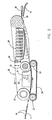
- Fig. 2 the paper or other substrate 7 enters between drive roll 20 and an opposing idler roll 22.
- a second idler roll 24 Spaced from idler roll 22 is a second idler roll 24, rolls 22 and 24 supporting an endless back-up belt 26 of silicone rubber.
- a second idler roll 28 Positioned substantially past roll 24 is a second idler roll 28, rolls 20 and 28 supporting an endless, heat resistant fuser belt 30.
- Opposite roll 24 and contacting the fuser belt 30 is an idler, pinch roll 32.
- a metal heater block 34 Positioned between rolls 20 and 32 and in contact with fuser belt 30 is a metal heater block 34 having a broad area of contact with belt 30.
- Block 34 has an internal infrared lamp 36 as a heat source.
- a metal heat sink 38 Positioned between rolls 32 and 28 is a metal heat sink 38 (having a number of fins to facilitate heat dispersion). As shown in solid line, heat sink 38 is not in contact with fuser belt 30 and therefore contributes little to cooling the substrate 7. As shown in dotted line, however, heat sink 38 is in broad contact with belt 30 and thus considerably increases cooling of substrate 7 on belt 30. Heat sink 38 may be moved between the two positions in any convenient manner, movement controller 40 being shown as a solenoid for purposes of illustration.
- a deflection finger 42 is positioned at roll 28 in slight contact or close proximity with belt 30 to direct substrate 7 in a guide 44 which directs substrate 7 to output bin 13.
- the document substrate 7 carrying toner 46 as a loose powder is fed between belts 26 and 30 with toner 46 facing belt 30 where it is firmly grasped between the nip of belt 26 and belt 30.
- Belts 26 and 30 are driven by drive roll 20 through their friction contact and therefore move at the same speed.
- Document 7 is moved under block 34 where the heat from block 34 is sufficient to melt or at least flow together toner 46 of document 7.
- Document 7 continues to move past the location of rolls 24 and 32.
- movement controller 40 is employed to have heat sink 34 away from belt 30 and finger 42 deflects document 7 from belt 30 while the toner still has some mobility. Since the toner has some affinity for belt 30, the resulting surface is rough.
- movement controller 40 is employed to have heat sink 38 in broad contact with belt 30. Finger 42 then deflects document 7 from belt 30 after the toner is so cool as to have no mobility or sufficient affinity to belt 30 to affect the surface of the toner. The resulting surface is smooth.
- Fig. 3 illustrates an alternative apparatus to that of Fig. 2, which employs two deflection fingers 50 and 52, one of which is selectable by a movement controller 54, shown illustratively as a solenoid. Elements corresponding directly with those of Fig. 2 are given the same reference numeral as in Fig. 2.
- a heat sink 53 is located in the position corresponding to sink 34 of Fig. 2, but sink 53 is stationary and functions only to permit a more compact design.
- Deflection finger 50 is positioned substantially closer to heater block 34 than finger 52. Finger 50 deflects document 7 into a guide path 58, which leads ultimately to bin 13. Documents 7 deflected by finger 52 are directed also to bin 13 through guide 60, which merges with guide path 58.
- movement controller 54 positions finger 50 into engagement with belt 30.
- a document 7, being moved continuously by belt 30 as described with respect to Fig. 2 has not fully cooled and therefore becomes rough when directed by finger 50.
- movement controller 54 positions finger 50 away from belt 30.
- a document 7 then moves a sufficient time with belt 30 for its toner to have cooled and have insufficient affinity for belt 30 to result in roughness when deflected by finger 52.
- a glossy or matte document may be obtained as desired.
- a glossy document is particularly important when it is a color transparency, since a rough transparency scatters the light.
- the belts 30 and 26 would be continuously cleaned by felt pads or the like mounted in contact with each belt 30 and 26. Variations and improvements within the scope of the claims may be envisaged.
Landscapes
- Physics & Mathematics (AREA)
- General Physics & Mathematics (AREA)
- Fixing For Electrophotography (AREA)
- Color Electrophotography (AREA)
Description
- This invention relates to printers employing thermal fixing of finely divided, powder toners. Such printers are often electrostatic, but powder toners may be applied to paper, transparent foils, or other substrates using magnetic and other techniques. The toner, when applied for development, may be suspended in liquid or air, brushed on, or applied by other techniques. The powders are then coalesced with heat by passing the substrate between a roller and a support where it is heated. At the end of such fixing the toner has a surface texture (termed "finish") which may be smooth or rough, depending on the overall characteristics of the fixing operation.
- A slightly rough finish of toner on ordinary paper is generally preferable since a smooth finish reflects light in a coherent manner (shines), which is distracting. A very smooth finish is necessary on a transparency which is to be optically projected since the rough finish scatters light transmitted through it and degrades the image projected, particularly multicolor images. Prior printer designs apparently have not been directed to this dichotomy. Various designs are known which roughen the texture of finished printing. Other designs, particularly, U.S. Patent No. 3,578,797 to Hodges, cool the fixed image before removing the toner from contact with the surface on which it is cooled. Controlling the degree of cooling to control roughness, however, is not disclosed.
- JP-63013088 discloses a method of selecting the glossiness of a copy image according to user's preference by varying heating value supplied from a roller couple to transfer paper which is fixed by a fixing device.
- US-3948215 discloses a method for preventing the offset phenomenon in fixing toner images formed by toner particles adhering to selected areas on support sheets.
- According to the invention, in an electrophotographic or other imaging system employing thermoplastic, powdered toner, a toned image is fixed in a system which permits selection of either glossy or non-glossy images. A belt fuser may be used, and non-glossy images are obtained by removing the document from contact with its surface while the toner is still mobile. A glossy image is achieved by allowing the toner to cool further. This is implemented by having an alterable heat sink or, alternatively, multiple removal stations.
- The details of this invention will be described in connection with the following embodiments, described by way of example only, and with reference to the accompanying drawings, in which:
- Fig. 1 is an illustrative drawing showing an imaging system or printer employing fixing of toner in accordance with this invention;
- Fig. 2 shows one alternative fixing system in accordance with this invention;
- and Fig. 3 shows a second alternative fixing system in accordance with this invention.
- This invention is applicable to any imaging system in which a powder toner is applied to define the image and then fixed with heat. Fig. 1 illustrates such a system in the form of an electrostatic printer. Image information is received at
input terminal 1. Such information typically is a sequence of character and spacing codes or data describing the entire page of a document to be printed in bit mapped form (each picture element or pel defined). This information is then applied optically to an electrostatically changedphotoconductive surface 3, and the electrostatic image so formed is then developed with toner attoning station 5. The paper orother substrate 7 being printed upon is contacted with the toner image with pressure at atransfer station 9.Paper 7 then entersfixing station 11, after whichpaper 7 is stacked in output hopper orbin 13. - As just described, most of the elements of the above imaging system are entirely conventional and therefore will not be discussed in further detail. In accordance with this invention, selection between glossy and non-glossy images is achieved in one alternative by the
fixing station 11 comprising the apparatus of Fig. 2. - In Fig. 2 the paper or
other substrate 7 enters betweendrive roll 20 and anopposing idler roll 22. Spaced fromidler roll 22 is asecond idler roll 24, rolls 22 and 24 supporting an endless back-up belt 26 of silicone rubber. Positioned substantiallypast roll 24 is asecond idler roll 28, rolls 20 and 28 supporting an endless, heatresistant fuser belt 30.Opposite roll 24 and contacting thefuser belt 30 is an idler,pinch roll 32. - Positioned between
rolls fuser belt 30 is ametal heater block 34 having a broad area of contact withbelt 30.Block 34 has an internalinfrared lamp 36 as a heat source. Positioned betweenrolls heat sink 38 is not in contact withfuser belt 30 and therefore contributes little to cooling thesubstrate 7. As shown in dotted line, however,heat sink 38 is in broad contact withbelt 30 and thus considerably increases cooling ofsubstrate 7 onbelt 30.Heat sink 38 may be moved between the two positions in any convenient manner,movement controller 40 being shown as a solenoid for purposes of illustration. - A
deflection finger 42 is positioned atroll 28 in slight contact or close proximity withbelt 30 todirect substrate 7 in aguide 44 which directssubstrate 7 tooutput bin 13. - In operation the
document substrate 7 carryingtoner 46 as a loose powder is fed betweenbelts toner 46 facingbelt 30 where it is firmly grasped between the nip ofbelt 26 andbelt 30.Belts drive roll 20 through their friction contact and therefore move at the same speed.Document 7 is moved underblock 34 where the heat fromblock 34 is sufficient to melt or at least flow togethertoner 46 ofdocument 7.Document 7 continues to move past the location ofrolls movement controller 40 is employed to haveheat sink 34 away frombelt 30 andfinger 42deflects document 7 frombelt 30 while the toner still has some mobility. Since the toner has some affinity forbelt 30, the resulting surface is rough. - When a smooth surface is desired for high gloss,
movement controller 40 is employed to haveheat sink 38 in broad contact withbelt 30.Finger 42 then deflectsdocument 7 frombelt 30 after the toner is so cool as to have no mobility or sufficient affinity to belt 30 to affect the surface of the toner. The resulting surface is smooth. - Fig. 3 illustrates an alternative apparatus to that of Fig. 2, which employs two
deflection fingers movement controller 54, shown illustratively as a solenoid. Elements corresponding directly with those of Fig. 2 are given the same reference numeral as in Fig. 2. Aheat sink 53 is located in the position corresponding tosink 34 of Fig. 2, butsink 53 is stationary and functions only to permit a more compact design.Deflection finger 50 is positioned substantially closer toheater block 34 thanfinger 52.Finger 50deflects document 7 into aguide path 58, which leads ultimately to bin 13.Documents 7 deflected byfinger 52 are directed also to bin 13 throughguide 60, which merges withguide path 58. - In operation of the apparatus of Fig. 3, when a matte surface is desired,
movement controller 54positions finger 50 into engagement withbelt 30. Adocument 7, being moved continuously bybelt 30 as described with respect to Fig. 2, has not fully cooled and therefore becomes rough when directed byfinger 50. When a smooth document is desired,movement controller 54positions finger 50 away frombelt 30. Adocument 7 then moves a sufficient time withbelt 30 for its toner to have cooled and have insufficient affinity forbelt 30 to result in roughness when deflected byfinger 52. - Thus, by selection of two cooling modes as described with respect to Fig. 2 and Fig. 3, a glossy or matte document may be obtained as desired. A glossy document is particularly important when it is a color transparency, since a rough transparency scatters the light. As is conventional, the
belts belt
Claims (6)
- An imaging system comprising imaging means to produce variable images on a document substrate (7) by means of a toner or thermoplastic powder (46), and a fixing station to fix said images on said substrate (7) comprising a heat source (36) in combination with a belt (30) to continuously contact said images on said substrate (7) while heating said substrate (7), said belt (30) contacting, in use, the images on the substrate (7) prior to their removal program, characterised in that said imaging system further comprises:
means to select one status in which said substrate (7) is removed from contact with said belt (30) when said belt (30) is at a first temperature and while said toner or thermoplastic powder (46) is at a temperature at which said toner or thermoplastic powder (46) is roughened as a consequence of its affinity to said belt (30) and to select a second status in which said substrate (7) is removed from contact with said belt (30) when said belt (30) is at a second temperature and said toner or thermoplastic powder (46) is at a lower temperature than that associated with said first status and is not roughened. - The imaging system as in claim 1 in which said means to select comprises a moveable heat sink.
- The imaging system as in claim 1 or 2 in which said means to select comprises first and second deflection means to direct said substrate (7) from said contact, said first deflection means being moveable into a position in which said document is removed when said toner or thermoplastic powder (46) is at the temperature of said one status and being moveable into a position in which said document is not removed, and said second deflection means being positioned to remove said document when said toner or thermoplastic powder (46) is at the temperature of said second status.
- An imaging system comprising means to produce variable images on a document substrate as a toner or thermoplastic powder (46), a first endless belt (30), a second endless belt (26) forming a nip to receive said document (7) and heat said toner or thermoplastic powder (46) to flow said toner or thermoplastic powder (46) together for coalescence with said toner or thermoplastic powder (46) in contact with said first belt (30), said first belt (30) being longer than said second belt (26), characterised in that said imaging system further comprises:
means to select one status in which said document (7) is removed from said first belt (30) while said toner or thermoplastic powder (46) is at a temperature at which said toner or thermoplastic powder (46) is roughened as a consequence of its affinity to said first belt (30) and to select a second status in which said document (7) is removed from said first belt (30) when said toner or thermoplastic powder (46) is at a lower temperature and is not roughened. - The imaging system as in claim 4 in which said means to select comprises a moveable heat sink.
- The imaging system as in claim 4 or 5 in which said means to select comprises first and second deflection means to direct said substrate (7) from said first belt (30), said first deflection means being moveable into a position in which said document is removed when said toner or thermoplastic powder (46) is at the temperature of said one status and being moveable into a position in which said document (7) is not removed, and said second deflection means being positioned to remove said document when said toner or thermoplastic powder (46) is at the temperature of said second status.
Applications Claiming Priority (2)
| Application Number | Priority Date | Filing Date | Title |
|---|---|---|---|
| US07/615,741 US5099288A (en) | 1990-11-19 | 1990-11-19 | Fixing device with selectable finish |
| US615741 | 1990-11-19 |
Publications (3)
| Publication Number | Publication Date |
|---|---|
| EP0487265A2 EP0487265A2 (en) | 1992-05-27 |
| EP0487265A3 EP0487265A3 (en) | 1993-03-17 |
| EP0487265B1 true EP0487265B1 (en) | 1996-01-31 |
Family
ID=24466630
Family Applications (1)
| Application Number | Title | Priority Date | Filing Date |
|---|---|---|---|
| EP91310567A Expired - Lifetime EP0487265B1 (en) | 1990-11-19 | 1991-11-15 | Fixing device with selectable finish |
Country Status (4)
| Country | Link |
|---|---|
| US (1) | US5099288A (en) |
| EP (1) | EP0487265B1 (en) |
| JP (1) | JP3271777B2 (en) |
| DE (1) | DE69116812T2 (en) |
Families Citing this family (40)
| Publication number | Priority date | Publication date | Assignee | Title |
|---|---|---|---|---|
| US5293537A (en) * | 1991-01-10 | 1994-03-08 | Delphax Systems | Image transport fusing system |
| JPH04284481A (en) * | 1991-03-14 | 1992-10-09 | Hitachi Koki Co Ltd | Thermal fixing device |
| JPH05142959A (en) * | 1991-11-20 | 1993-06-11 | Konica Corp | Color image forming device |
| US5196894A (en) * | 1992-01-03 | 1993-03-23 | Eastman Kodak Company | Toner image fusing and cooling method and apparatus |
| US5153411A (en) * | 1992-02-28 | 1992-10-06 | Eastman Kodak Company | Fuser roller having surface-temperature reducing member |
| JPH05341672A (en) * | 1992-06-05 | 1993-12-24 | Hitachi Koki Co Ltd | Thermal fixing device |
| US5563694A (en) * | 1993-01-15 | 1996-10-08 | Canon Kabushiki Kaisha | Printer apparatus for forming an embossed image |
| US5887235A (en) * | 1993-12-16 | 1999-03-23 | Xerox Corporation | Variable gloss fuser |
| US5450182A (en) * | 1993-12-16 | 1995-09-12 | Xerox Corporation | Apparatus and method for fusing toner images on transparent substrates |
| US5873020A (en) * | 1995-11-13 | 1999-02-16 | Minolta Co., Ltd. | Fixing device with endless belt |
| US5998761A (en) * | 1998-07-10 | 1999-12-07 | Xerox Corporation | Variable dwell fuser |
| US6272310B1 (en) * | 1999-10-20 | 2001-08-07 | Lexmark International, Inc. | Toner fuser system having post-fuser media conditioner |
| JP3945281B2 (en) * | 2002-03-19 | 2007-07-18 | 富士ゼロックス株式会社 | Image forming apparatus |
| US6856784B2 (en) * | 2002-08-29 | 2005-02-15 | Xerox Corporation | Compact belt fuser apparatus with floating idler rollers supported by belt |
| JP2004157412A (en) * | 2002-11-07 | 2004-06-03 | Fuji Photo Film Co Ltd | Electrophotographic image forming method and electrophotographic print |
| US20050158089A1 (en) * | 2004-01-15 | 2005-07-21 | Xerox Corporation | Two stage fusing method and apparatus for high-speed full process color |
| US7088946B2 (en) * | 2004-04-12 | 2006-08-08 | Eastman Kodak Company | Adjusting gloss for a print image |
| JP4994626B2 (en) * | 2005-09-13 | 2012-08-08 | キヤノン株式会社 | Image heating apparatus and image forming apparatus |
| JP5482104B2 (en) * | 2009-09-15 | 2014-04-23 | 株式会社リコー | Fixing apparatus and image forming apparatus |
| DE102009058960A1 (en) * | 2009-12-18 | 2011-06-22 | Eastman Kodak Co., N.Y. | Apparatus and method for applying and fixing a toner image on a substrate |
| JP2012181337A (en) * | 2011-03-01 | 2012-09-20 | Ricoh Co Ltd | Gloss imparting device and image forming apparatus using the same |
| JP5836631B2 (en) * | 2011-04-25 | 2015-12-24 | キヤノン株式会社 | Film cartridge for surface treatment equipment |
| JP2013003517A (en) * | 2011-06-21 | 2013-01-07 | Ricoh Co Ltd | Glossiness applying device, fixing device and image forming apparatus |
| US8488994B2 (en) | 2011-09-23 | 2013-07-16 | Stratasys, Inc. | Electrophotography-based additive manufacturing system with transfer-medium service loops |
| US8879957B2 (en) | 2011-09-23 | 2014-11-04 | Stratasys, Inc. | Electrophotography-based additive manufacturing system with reciprocating operation |
| US20130186558A1 (en) | 2011-09-23 | 2013-07-25 | Stratasys, Inc. | Layer transfusion with heat capacitor belt for additive manufacturing |
| US9885987B2 (en) | 2011-09-23 | 2018-02-06 | Stratasys, Inc. | Layer transfusion for additive manufacturing |
| JP5891764B2 (en) * | 2011-12-12 | 2016-03-23 | 株式会社リコー | Glossiness imparting apparatus and image forming apparatus |
| JP2013140214A (en) * | 2011-12-28 | 2013-07-18 | Ricoh Co Ltd | Image forming device |
| US9023566B2 (en) | 2013-07-17 | 2015-05-05 | Stratasys, Inc. | ABS part material for electrophotography-based additive manufacturing |
| US9144940B2 (en) | 2013-07-17 | 2015-09-29 | Stratasys, Inc. | Method for printing 3D parts and support structures with electrophotography-based additive manufacturing |
| US9029058B2 (en) | 2013-07-17 | 2015-05-12 | Stratasys, Inc. | Soluble support material for electrophotography-based additive manufacturing |
| JP6191912B2 (en) * | 2013-09-17 | 2017-09-06 | 株式会社リコー | Sheet conveying mechanism, cooling device, and image forming apparatus |
| US9770869B2 (en) | 2014-03-18 | 2017-09-26 | Stratasys, Inc. | Additive manufacturing with virtual planarization control |
| US10011071B2 (en) | 2014-03-18 | 2018-07-03 | Evolve Additive Solutions, Inc. | Additive manufacturing using density feedback control |
| US10144175B2 (en) | 2014-03-18 | 2018-12-04 | Evolve Additive Solutions, Inc. | Electrophotography-based additive manufacturing with solvent-assisted planarization |
| US9643357B2 (en) | 2014-03-18 | 2017-05-09 | Stratasys, Inc. | Electrophotography-based additive manufacturing with powder density detection and utilization |
| US9868255B2 (en) | 2014-03-18 | 2018-01-16 | Stratasys, Inc. | Electrophotography-based additive manufacturing with pre-sintering |
| US9688027B2 (en) | 2014-04-01 | 2017-06-27 | Stratasys, Inc. | Electrophotography-based additive manufacturing with overlay control |
| US9919479B2 (en) | 2014-04-01 | 2018-03-20 | Stratasys, Inc. | Registration and overlay error correction of electrophotographically formed elements in an additive manufacturing system |
Family Cites Families (15)
| Publication number | Priority date | Publication date | Assignee | Title |
|---|---|---|---|---|
| US3478665A (en) * | 1966-07-27 | 1969-11-18 | Ricoh Kk | Developing apparatus for sensitive paper |
| US3578797A (en) * | 1969-09-26 | 1971-05-18 | Eastman Kodak Co | Fusing method and apparatus |
| US3948215A (en) * | 1972-03-14 | 1976-04-06 | Ricoh Co., Ltd. | Fixing toner images in electrophotography |
| US3965331A (en) * | 1975-02-24 | 1976-06-22 | Xerox Corporation | Dual mode roll fuser |
| JPS53132352A (en) * | 1977-04-22 | 1978-11-18 | Sharp Corp | Electrophotographic copier |
| US4242566A (en) * | 1980-03-21 | 1980-12-30 | Pitney Bowes Inc. | Heat-pressure fusing device |
| JPS6125173A (en) * | 1984-07-13 | 1986-02-04 | Nec Corp | Fixing device of electrophotographic printing device |
| US4563073A (en) * | 1984-10-31 | 1986-01-07 | Xerox Corporation | Low mass heat and pressure fuser and release agent management system therefor |
| JPS6313088A (en) * | 1986-07-04 | 1988-01-20 | Ricoh Co Ltd | Full-color copying machine |
| US4791447A (en) * | 1987-08-31 | 1988-12-13 | Xerox Corporation | Dual mode color fuser |
| JPH0250160A (en) * | 1988-05-12 | 1990-02-20 | Seiko Instr Inc | Heat fixing device |
| JPH0264640A (en) * | 1988-08-31 | 1990-03-05 | Brother Ind Ltd | Method and device for image gloss processing |
| JPH0679186B2 (en) * | 1988-09-07 | 1994-10-05 | キヤノン株式会社 | Fixing device |
| JP2646444B2 (en) * | 1988-12-12 | 1997-08-27 | キヤノン株式会社 | Image heating fixing device |
| US5019869A (en) * | 1989-03-21 | 1991-05-28 | Eastman Kodak Company | Toner fusing/finishing device for selecting alternatively the style of finishing on a glossy, matte, or textured print finish |
-
1990
- 1990-11-19 US US07/615,741 patent/US5099288A/en not_active Expired - Lifetime
-
1991
- 1991-11-15 EP EP91310567A patent/EP0487265B1/en not_active Expired - Lifetime
- 1991-11-15 DE DE69116812T patent/DE69116812T2/en not_active Expired - Fee Related
- 1991-11-19 JP JP35170691A patent/JP3271777B2/en not_active Expired - Fee Related
Also Published As
| Publication number | Publication date |
|---|---|
| DE69116812D1 (en) | 1996-03-14 |
| JPH05188802A (en) | 1993-07-30 |
| US5099288A (en) | 1992-03-24 |
| EP0487265A3 (en) | 1993-03-17 |
| JP3271777B2 (en) | 2002-04-08 |
| DE69116812T2 (en) | 1996-08-29 |
| EP0487265A2 (en) | 1992-05-27 |
Similar Documents
| Publication | Publication Date | Title |
|---|---|---|
| EP0487265B1 (en) | Fixing device with selectable finish | |
| US7457557B2 (en) | High precision-heating and fusing apparatus | |
| US6778804B2 (en) | Fixing device and image forming apparatus including the same | |
| EP0404112B1 (en) | An image fixing apparatus | |
| US5247336A (en) | Image fusing apparatus having heating and cooling devices | |
| US5539511A (en) | Multilevel/duplex image sheet decurling apparatus | |
| US5436711A (en) | Multilevel fusing apparatus | |
| US5887235A (en) | Variable gloss fuser | |
| US5051780A (en) | Fusing temperature control device for a printer or similar apparatus | |
| US5852763A (en) | Image heating apparatus | |
| US5998761A (en) | Variable dwell fuser | |
| CN100426155C (en) | Image forming apparatus | |
| US5019869A (en) | Toner fusing/finishing device for selecting alternatively the style of finishing on a glossy, matte, or textured print finish | |
| US6640062B2 (en) | Toner image fixing device provided with a sheet separating portion | |
| US6687468B2 (en) | Multi-position fuser nip cam | |
| US20090154943A1 (en) | On demand fuser and related method | |
| US5436712A (en) | Power control for instant-on-integral resistive heating belt fuser | |
| US7057141B1 (en) | Temperature control method and apparatus | |
| US5321481A (en) | Fuser temperature and copy output controller | |
| US5450182A (en) | Apparatus and method for fusing toner images on transparent substrates | |
| US5893018A (en) | Single-pass, multi-color electrostatographic printer with continuous path transfer member | |
| US20080138102A1 (en) | Rapid warm-up and cool-down pressure roll assembly and a fusing apparatus including same | |
| JPH08220928A (en) | Image forming device | |
| US5325164A (en) | Fixing device with pulling rollers | |
| US5483331A (en) | Textured contact rollers and the method of using them for improving electrical contact with a fuser belt fusing |
Legal Events
| Date | Code | Title | Description |
|---|---|---|---|
| PUAI | Public reference made under article 153(3) epc to a published international application that has entered the european phase |
Free format text: ORIGINAL CODE: 0009012 |
|
| 111Z | Information provided on other rights and legal means of execution |
Free format text: DE FR GB |
|
| AK | Designated contracting states |
Kind code of ref document: A2 Designated state(s): DE FR GB |
|
| PUAL | Search report despatched |
Free format text: ORIGINAL CODE: 0009013 |
|
| AK | Designated contracting states |
Kind code of ref document: A3 Designated state(s): DE FR GB |
|
| 17P | Request for examination filed |
Effective date: 19930906 |
|
| 17Q | First examination report despatched |
Effective date: 19940621 |
|
| GRAA | (expected) grant |
Free format text: ORIGINAL CODE: 0009210 |
|
| AK | Designated contracting states |
Kind code of ref document: B1 Designated state(s): DE FR GB |
|
| REF | Corresponds to: |
Ref document number: 69116812 Country of ref document: DE Date of ref document: 19960314 |
|
| ET | Fr: translation filed | ||
| PLBE | No opposition filed within time limit |
Free format text: ORIGINAL CODE: 0009261 |
|
| STAA | Information on the status of an ep patent application or granted ep patent |
Free format text: STATUS: NO OPPOSITION FILED WITHIN TIME LIMIT |
|
| 26N | No opposition filed | ||
| REG | Reference to a national code |
Ref country code: GB Ref legal event code: IF02 |
|
| PGFP | Annual fee paid to national office [announced via postgrant information from national office to epo] |
Ref country code: GB Payment date: 20071128 Year of fee payment: 17 Ref country code: FR Payment date: 20071119 Year of fee payment: 17 |
|
| PGFP | Annual fee paid to national office [announced via postgrant information from national office to epo] |
Ref country code: DE Payment date: 20071221 Year of fee payment: 17 |
|
| GBPC | Gb: european patent ceased through non-payment of renewal fee |
Effective date: 20081115 |
|
| REG | Reference to a national code |
Ref country code: FR Ref legal event code: ST Effective date: 20090731 |
|
| PG25 | Lapsed in a contracting state [announced via postgrant information from national office to epo] |
Ref country code: DE Free format text: LAPSE BECAUSE OF NON-PAYMENT OF DUE FEES Effective date: 20090603 |
|
| PG25 | Lapsed in a contracting state [announced via postgrant information from national office to epo] |
Ref country code: GB Free format text: LAPSE BECAUSE OF NON-PAYMENT OF DUE FEES Effective date: 20081115 |
|
| PG25 | Lapsed in a contracting state [announced via postgrant information from national office to epo] |
Ref country code: FR Free format text: LAPSE BECAUSE OF NON-PAYMENT OF DUE FEES Effective date: 20081130 |