EP0486834B1 - Multi-access method and mobile radiocommunication system implementing said multi-access method - Google Patents
Multi-access method and mobile radiocommunication system implementing said multi-access method Download PDFInfo
- Publication number
- EP0486834B1 EP0486834B1 EP91118102A EP91118102A EP0486834B1 EP 0486834 B1 EP0486834 B1 EP 0486834B1 EP 91118102 A EP91118102 A EP 91118102A EP 91118102 A EP91118102 A EP 91118102A EP 0486834 B1 EP0486834 B1 EP 0486834B1
- Authority
- EP
- European Patent Office
- Prior art keywords
- sequence
- data streams
- spread
- delta
- filter
- Prior art date
- Legal status (The legal status is an assumption and is not a legal conclusion. Google has not performed a legal analysis and makes no representation as to the accuracy of the status listed.)
- Expired - Lifetime
Links
Images

Classifications
-
- H—ELECTRICITY
- H04—ELECTRIC COMMUNICATION TECHNIQUE
- H04J—MULTIPLEX COMMUNICATION
- H04J13/00—Code division multiplex systems
- H04J13/0074—Code shifting or hopping
-
- H—ELECTRICITY
- H04—ELECTRIC COMMUNICATION TECHNIQUE
- H04B—TRANSMISSION
- H04B1/00—Details of transmission systems, not covered by a single one of groups H04B3/00 - H04B13/00; Details of transmission systems not characterised by the medium used for transmission
- H04B1/69—Spread spectrum techniques
- H04B1/707—Spread spectrum techniques using direct sequence modulation
- H04B1/7097—Interference-related aspects
- H04B1/7103—Interference-related aspects the interference being multiple access interference
-
- H—ELECTRICITY
- H04—ELECTRIC COMMUNICATION TECHNIQUE
- H04B—TRANSMISSION
- H04B2201/00—Indexing scheme relating to details of transmission systems not covered by a single group of H04B3/00 - H04B13/00
- H04B2201/69—Orthogonal indexing scheme relating to spread spectrum techniques in general
- H04B2201/707—Orthogonal indexing scheme relating to spread spectrum techniques in general relating to direct sequence modulation
- H04B2201/7097—Direct sequence modulation interference
- H04B2201/709709—Methods of preventing interference
-
- H—ELECTRICITY
- H04—ELECTRIC COMMUNICATION TECHNIQUE
- H04J—MULTIPLEX COMMUNICATION
- H04J13/00—Code division multiplex systems
- H04J13/0007—Code type
- H04J13/0022—PN, e.g. Kronecker
Definitions
- the invention relates to a multiple access method for the simultaneous exchange of several data streams between several participants in a transmission system, wherein different data streams with the same spreading sequence are spread to form a corresponding DSSS signal and the different DSSS signals are superimposed on the transmission to form a single received signal.
- the signals from different participants should ideally be orthogonal. Ie that the receiver of the mobile station resp. the base station that the base station resp. the mobile station can filter out the signal intended for it in such a way that no signal components from other users are available.
- DSSS-CDMA Direct Sequence Spread Spectrum
- CDMA Code Division Multiple Access
- TDMA Time Division Multiple Access
- TDMA time division multiple access
- each symbol of the data stream is multiplied and transmitted by a predetermined spreading sequence.
- each data bit determines the polarity of an entire pulse sequence made up of L "chips".
- a chip can have the value +1 or -1. So that the individual users can be separated, each is assigned its own spreading sequence.
- the transmitted signal is processed by a filter bank with K matched filters.
- Each of the K filters is adapted to the spreading sequence of one of the users.
- the sequences have to be defined in such a way that the cross-correlation between different spreading sequences and thus also the interference between the different data streams is as small as possible.
- CDMA systems are no longer necessary to maintain precise synchronization between the participants. In fact, such systems are usually operated completely asynchronously.
- Another advantage is that the transmitters transmit continuously. I.e. the peak power essentially coincides with the average power.
- the main disadvantage is that the interference from other users cannot be neglected. This interference is particularly pronounced when users are received with very different field strengths ("near-far effect"). For this reason, the transmission line of the users is often regulated.
- the ratio of peak power to average power can be kept low, as in CDMA, but the good properties of the Aloha principle with regard to preventing packet collisions in the time domain (so-called "collision resolution") are not greatly deteriorated.
- a disadvantage of the method is that the spread cannot be completely reversed by matched filtering.
- the object of the invention is to provide a multiple access method of the type mentioned at the outset which avoids the problems existing in the prior art.
- the aim of the invention is to propose a system which enables a large number of subscribers to share the same frequency spectrum in a manner which is advantageous compared to both TDMA and DSSS-CDMA.
- the solution consists in filtering the received signal in a filter that is inverse with respect to the common spreading sequence in order to detect the different data streams in a receiver, and in that the superimposition is carried out in such a way that the spreading sequence intervals belonging to different data streams are shifted in time from one another by a predetermined minimum value .
- the essence of the method according to the invention is the use of an inverse filter instead of a matched filter. This enables the implementation of a multiple access system, that avoids the so-called inter-user interference without requiring precise synchronization.
- the time shift of the spreading sequence intervals belonging to different data streams is greater than the duration of a chip plus the duration of the burst response of a channel used for the transmission of the corresponding DSSS signal. This allows the individual users to be clearly separated from one another. It is also possible to estimate the channel impulse response for each transmission channel in the detector.
- the protocol becomes particularly simple if the time shift compared to neighboring spreading sequence intervals is approximately the same for all spreading sequence intervals belonging to different data streams.
- the inverse filter is a discrete-time filter that responds to the specified spreading sequence as such with a Kronecker delta sequence.
- An optimal or at least relatively optimal spreading sequence s [.] Is determined such that the process gain G, defined by the inverse of the energy of the associated inverse filter: with respect to all or as many spreading sequences of given length L as possible.
- One way to ensure that the minimum time intervals are observed is to transmit synchronization signals to the participants in the transmission system via a separate channel.
- the method according to the invention is well suited for mobile radio systems.
- One example is microcellular mobile radio, where the mobile subscriber stations move within a radius of typically several meters to a maximum of about 100 meters of a base station.
- Fig. 1 illustrates the principle of the invention.
- the transmission should take place in the same HF range.
- several transmitters will modulate their data streams onto a carrier oscillation, the frequency of which is the same for all.
- the data streams ⁇ B 1, m ⁇ , ⁇ B 2, m ⁇ , ⁇ B 3, m ⁇ contain digital (eg binary) data in the form of symbols B 1, m , B 2, m , B 3, m , which in the each data stream occur with a predetermined symbol duration T.
- the result of this transition from T to T / L is a DSSS signal ⁇ B 1, m s [.] ⁇ .
- Each data stream ⁇ B 1, m ⁇ , ⁇ B 2, m ⁇ , ⁇ B 3, m ⁇ becomes a corresponding DSSS signal (B 1, m s [.] ⁇ , ⁇ B 2, m s [.] ⁇ , ⁇ B 3, m s [.] ⁇
- the third te DSSS signal ⁇ B 3, m s [.] ⁇ is delayed by Delta_T compared to the second ⁇ B 2, m s [.] ⁇ and by 2 Delta_T compared to the first ⁇ B 1, m s [.] ⁇ .
- a receiver who is interested in a specific one of the data streams must therefore first filter this out of the received signal. According to the invention, this is done with an approximate inverse filter.
- the ideal inverse filter sought is an inverse filter with regard to the spreading sequence. This has the property that it responds to the specified spreading sequence as such with a pure Kronecker delta sequence ⁇ [k]. This will be explained in more detail below.
- the receiver differs from a known DSSS receiver by the use of an approximate inverse filter instead of a matched filter.
- the inverse filter has a completely different effect. His response to the spreading sequence as such produces a Kronecker delta sequence. As is known, such a sequence is distinguished by the fact that it has only one sample value that is different from zero.
- the impulse response of the filter is limited to a length -M1 ⁇ k ⁇ L + M2. Outside this window, the filter coefficients v [k] are identical to zero.
- the filter coefficients v [k] other than zero are selected according to the invention such that when the filter is excited by the spreading sequence, the resulting output signal approximates the Kronecker delta sequence as closely as possible.
- the coefficients v [k] of the ideal inverse filter decay exponentially in the case of a suitably selected spreading sequence for large k, reasonably good results can also be achieved with filters of reasonable length.
- the filter coefficients correspond to the ideal case, outside the specified range they are simply set to zero.
- the approximate inverse filter thus corresponds to the cut off ideal inverse filter (M 1 and M 2 are predeterminable numbers, ie so-called design parameters).
- the approximated inverse filter responds when excited by the specified spreading sequence s [.] As such with an output sequence which approximates the Kronecker delta sequence in the sense of the smallest error squares.
- the output sequence has a maximum peak / off peak ratio in the case mentioned. I.e. the largest secondary peak is made as small as possible in relation to the main peak. This is an approximate realization of the infinitely large peak / off peak ratio of a Kronecker delta sequence.
- the received signal is filtered with an inverse filter, this has the consequence that a signal is produced which can be divided into periodically recurring time slots, each time slot containing information about a symbol.
- the length of a time slot corresponds to the time shift of the various corresponding DSSS signals ⁇ B 1, ms [.] ⁇ , ⁇ B 2, ms [.] ⁇ , ⁇ B 3, ms [.] ⁇ In the transmitters.
- the different data streams come from different subscribers.
- An undeformed DSSS signal produces a sequence of pulses at the filter output mentioned.
- the pulses have a time interval T (symbol duration) and are weighted in accordance with the respective symbol value of the data stream.
- the output signal Y [k] shown in FIG. 2 is therefore composed in principle of weighted channel impulse responses.
- Y [k] has essentially (ie apart from noise components) the course B 1, m h 1, B 1, m denoting the symbol value and h 1 the channel shock response of the channel between the first user and the receiver.
- the output signal corresponds analogously to that with the next one Symbol value of the data stream multiplied channel impulse response: B 1, m + 1 h 1 .
- the receiver extracts all the associated time slots (ie for the kth data stream, the kth time slots of a frame from K time slots), filters this extracted signal with a channel-matched matched filter (whose shock response is known to be h * [-. ] is), extracts the real part of the resulting signal and performs a threshold detection.
- ML maximum likelihood
- the time shift Delta_T of the spreading sequence intervals belonging to different data streams is greater than the duration of the burst response of a channel used for the transmission of the corresponding DSSS signal.
- the individual users can be clearly separated from one another because the signal components belonging to different data streams in the received signal do not overlap in any way. It is also possible, according to an advantageous embodiment estimate the channel shock response for each transmission channel with the detector.
- the time shift should not fall below a predetermined minimum value, otherwise the received signal can no longer be demultiplexed.
- This lower limit preferably corresponds to the longest occurring channel impulse response plus a chip duration and is essentially the same for all DSSS signals.
- time shift Delta_T is set once and for all (e.g. when implementing the system). However, there is also the possibility of adapting them to the specific circumstances of the transmission channels.
- a preferred alternative is to provide a separate synchronization channel in addition to the common data channel during the implementation.
- this synchronization channel e.g. by the base station
- synchronization signals for compliance with the minimum time intervals are sent to the participants in the transmission system.
- additional channels are e.g. also used in TDMA systems.
- the spreading sequence s [.] Is defined such that the process gain G, defined by the inverse of the energy of the associated inverse filter: with respect to as many, in particular all, spreading sequences of the same length is maximal.
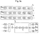
- 3a, b shows a block diagram of a mobile radio system according to the invention. It includes a base station T0 and K mobile subscriber stations T1, ..., T K. All stations are equipped with both a transmitter and a receiver circuit to enable two-way communication.
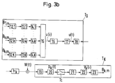
- Fig. 3a the transmitters of the subscriber stations T1, ..., T K and the receiver of the base station T0 and in Fig. 3b the receivers of the subscriber stations T1, ..., T K and the transmitter of the base station T0 are shown.
- a delay element 2.K brings the required time shift (K-1) T C towards the other participants in the data stream.
- the spreading sequence generator 3.K the predetermined common spreading sequence s [.] Is multiplied by the symbol value present in each case.
- the digital DSSS signal is generated in this way. With a pulse modulator 4.K and a low-pass filter 5.K, a continuous-time DSSS signal is generated, which is then modulated onto a carrier oscillation in a conventional modulator 6.K.
- the individual subscriber stations T1, ..., T K are in principle all the same. In operation, they differ only in the delay with which they provide their data stream.
- the signals are deformed and noisy through the respective channels h 1, h 2, ..., h K (additive white Gaussian noise W (t)).
- the signals from the various subscriber stations ( ⁇ ) overlap in the receiver.
- the receiver of the base station T0 demodulates the carrier oscillation (demodulator 7), filters out the relevant frequency range (filter 8) and samples the filtered signal at the chip rate 1 / T C.
- the received signal X [i] is filtered with an inverse filter 9. This gives an output signal Y [k] with the properties explained with reference to FIG. 2.
- a selection circuit 10 extracts the time slots belonging to the same data stream.
- An ML detector 11.1, ..., 11.K then follows for each data stream.
- the delayed signals are processed in spreading sequence generators 14.1 ... 14.K into DSSS signals.
- a summing circuit 15 superimposes the K DSSS signals into a digital transmission signal U (i). This is processed in a manner known per se using a pulse modulator 16 and a low-pass filter 17 to form a continuous-time signal U (t).
- a modulator 18 modulates a predetermined carrier oscillation in accordance with the continuous-time signal U (t).
- the modulated carrier oscillation When transmitted to the k-th subscriber station T k , the modulated carrier oscillation undergoes deformation in the channel h k and is impaired by an additive white Gaussian noise W (t).
- the subscriber station T k demodulates the carrier oscillation and filters out the desired frequency range (demodulator 19, filter 20).
- the resulting received signal X k (t) is sampled with an integer multiple of the chip rate 1 / T C and then filtered with the inverse filter 21.
- the sampled received signal is thereby despread.
- a selection circuit 22 extracts the time slots assigned to the subscriber station T k (for example always the kth from a frame of K time slots) in accordance with the method according to the invention. In this way, a signal Y k is obtained, from which the data stream (B k, m marked with a roof) can be estimated with an ML detector 23.
- the invention creates a multiple access method which combines the advantages of TDMA and CDMA.
- a practically total separation of users is possible without the need for the precision of synchronization that is customary with TDMA.
Abstract
Description
Die Erfindung betrifft ein Mehrfachzugriffsverfahren zum gleichzeitigen Austauschen von mehreren Datenströmen zwischen mehreren Teilnehmern eines Uebertragungssystems, wobei verschiedene Datenströme mit der gleichen Spreizsequenz zu einem entsprechenden DSSS-Signal gespreizt werden und die verschiedenen DSSS-Signale bei der Uebertragung zu einem einzigen Empfangssignal überlagert werden.The invention relates to a multiple access method for the simultaneous exchange of several data streams between several participants in a transmission system, wherein different data streams with the same spreading sequence are spread to form a corresponding DSSS signal and the different DSSS signals are superimposed on the transmission to form a single received signal.
In der Mobilfunktechnik werden praktisch immer mehrere Benützer gleichzeitig von einer einzigen Basisstation bedient. Die Signale verschiedener Teilnehmer sollten bei einem solchen System idealerweise orthogonal sein. D.h. dass der Empfänger der Mobilstation resp. der Basisstation das von der Basisstation resp. der Mobilstation für ihn bestimmte Signal so herausfiltern kann, dass keinerlei Signalanteile von anderen Benützern mehr vorhanden sind.In mobile radio technology, several users are practically always served by a single base station. With such a system, the signals from different participants should ideally be orthogonal. Ie that the receiver of the mobile station resp. the base station that the base station resp. the mobile station can filter out the signal intended for it in such a way that no signal components from other users are available.
Neben den gebräuchlichen Zeit- und Frequenzmultiplexverfahren kann zu diesem Zweck auch die DSSS-CDMA-Technik (DSSS = Direct Sequence Spread Spectrum, CDMA = Code Division Multiple Access) eingesetzt werden.In addition to the common time and frequency division multiplex methods, DSSS-CDMA technology (DSSS = Direct Sequence Spread Spectrum, CDMA = Code Division Multiple Access) can also be used for this purpose.
Bei TDMA-Systemen (TDMA = Time Division Multiple Access) wird die Zeitachse in Schlitze einer gegebenen Länge T aufgeteilt. Einem Benutzer wird sodann in einem bestimmten Zeitrahmen aus K Schlitzen stets der k-te so zugeteilt, dass nie zwei Benutzer im gleichen Schlitz senden.In TDMA systems (TDMA = Time Division Multiple Access), the time axis is divided into slots of a given length T. A user is then always allocated the kth in a certain time frame from K slots in such a way that two users never transmit in the same slot.
Der Hauptvorteil von TDMA-Systemen besteht darin, dass es im wesentlichen keine Interferenz zwischen verschiedenen Benutzern gibt. Der Preis, der dafür zu bezahlen ist, ist die hohe Präzision der Synchronisation der K Benutzer. Ein zweiter signifikanter Nachteil stellt die hohe Spitzenleistung dar: Jeder Sender muss als Spitzenleistung (peak power) das K-fache seiner Durchschnittsleistung erbringen können. Schliesslich ist das System ziemlich unflexibel: Es werden spezielle Protokolle benötigt, um neuen Benützern Zeitschlitze (sog. Slots) zuweisen zu können, und zwar selbst wenn die Slots schwach besetzt sind, d.h. wenn nur ein kleiner Teil der maximal zugelassenen Teilnehmer aktiv ist.The main advantage of TDMA systems is that there is essentially no interference between different users. The price to pay for this is the high precision of the synchronization of the K users. A second significant disadvantage is the high peak power: Each transmitter must be able to provide K times its average power as peak power. Finally, the system is quite inflexible: special protocols are required to assign time slots (so-called slots) to new users, even if the slots are sparsely populated, i.e. if only a small part of the maximum number of participants is active.
Bei DSSS-CDMA-Systemen wird jedes Symbol des Datenstroms mit einer vorgegebenen Spreizsequenz multipliziert und übertragen. Im binären Fall bestimmt jedes Datenbit die Polarität einer ganzen Pulssequenz aus L "Chips". Ein Chip kann dabei den Wert +1 oder -1 annehmen. Damit die einzelnen Benützer getrennt werden können, wird jedem eine eigene Spreizsequenz zugeordnet. Im Empfänger wird das übertragene Signal von einer Filterbank mit K Matched Filtern verarbeitet. Jedes der K Filter ist an die Spreizsequenz eines der Benutzer angepasst. Für ein optimales System sind die Sequenzen so festzulegen, dass die Kreuzkorrelation zwischen verschiedenen Spreizsequenzen und damit auch die Interferenz zwischen den verschiedenen Datenströmen möglichst klein wird.In DSSS-CDMA systems, each symbol of the data stream is multiplied and transmitted by a predetermined spreading sequence. In the binary case, each data bit determines the polarity of an entire pulse sequence made up of L "chips". A chip can have the value +1 or -1. So that the individual users can be separated, each is assigned its own spreading sequence. In the receiver, the transmitted signal is processed by a filter bank with K matched filters. Each of the K filters is adapted to the spreading sequence of one of the users. For an optimal system, the sequences have to be defined in such a way that the cross-correlation between different spreading sequences and thus also the interference between the different data streams is as small as possible.
Eine Analyse eines DSSS-CDMA-Systems beinhaltet der Artikel "Performance Evaluation for Phase-Coded Spread-Spectrum Multiple-Access Communication - Part I + II", Michael B. Pursley, IEEE Trans. on Communications, Vol. COM-25, Nr. 8, August 1977, pp. 795-803.An analysis of a DSSS-CDMA system includes the article "Performance Evaluation for Phase-Coded Spread-Spectrum Multiple-Access Communication - Part I + II", Michael B. Pursley, IEEE Trans. On Communications, Vol. COM-25, no 8, August 1977, pp. 795-803.
Der Hauptvorteil der CDMA-Systeme liegt darin, dass es nicht mehr nötig ist, zwischen den Teilnehmern eine genaue Synchronisation aufrechtzuerhalten. In der Tat werden solche Systeme in der Regel völlig asynchron betrieben. Ein weiterer Vorteil ergibt sich daraus, dass die Sender kontinuierlich senden. D.h. die Spitzenleistung fällt im wesentlichen mit der Durchschnittsleistung zusammen.The main advantage of CDMA systems is that it is no longer necessary to maintain precise synchronization between the participants. In fact, such systems are usually operated completely asynchronously. Another advantage is that the transmitters transmit continuously. I.e. the peak power essentially coincides with the average power.
Der wesentliche Nachteil ist darin zu sehen, dass die Interferenz von anderen Benutzern her insgesamt nicht vernachlässigt werden kann. Diese Interferenz ist insbesondere dann ausgeprägt, wenn die Benützer mit stark unterschiedlichen Feldstärken empfangen werden ("Near-Far-Effect"). Aus diesem Grund wird oft die Sendeleitung der Benützer geregelt.The main disadvantage is that the interference from other users cannot be neglected. This interference is particularly pronounced when users are received with very different field strengths ("near-far effect"). For this reason, the transmission line of the users is often regulated.
Ueblicherweise begrenzt diese Interferenz und nicht das thermische Rauschen die maximale Anzahl der Benutzer. Aus schaltungstechnischer Sicht ist es schliesslich nachteilig, dass im Empfänger soviele Matched Filter benötigt werden, wie Benützer vorhanden sind. Nicht selten ist dies der Grund, weshalb bei der Realisierung von Mobilfunksystemen zuungunsten von CDMA entschieden wird.Usually this interference and not thermal noise limits the maximum number of users. From the point of view of circuit technology, it is ultimately disadvantageous that as many matched filters are required in the receiver as there are users. This is not infrequently the reason why CDMA is chosen to the disadvantage in the implementation of mobile radio systems.
In der Veröffentlichung "Development of the ALOHANET", N. Abramson, IEEE Trans. on Information Theory, Vol. II-31, No. 2, March 1985, wird ein sog. "Spread Aloha" Verfahren vorgeschlagen. Dabei wird im Aloha Kanal eine zeitliche Spreizung eingefügt, d.h. jedes Datenpaket wird den Chips einer binären Sequenz entsprechend gewichtet und mehrmals übertragen. Im Empfänger wird der zeitlich gespreizte Datenstrom durch Matched Filterung wieder annähernd auf die Dauer eines Datenpakets komprimiert.In the publication "Development of the ALOHANET", N. Abramson, IEEE Trans. On Information Theory, Vol. II-31, No. 2, March 1985, a so-called "Spread Aloha" procedure is proposed. A time spread is inserted in the Aloha channel, ie each data packet is weighted according to the chips of a binary sequence and transmitted several times. In the receiver, the spread data stream is matched Filtering compressed again approximately to the duration of a data packet.
Durch die zeitliche Spreizung kann also das Verhältnis von Spitzenleistung zu Durchschnittsleistung wie bei CDMA klein gehalten werden, wobei jedoch die guten Eigenschaften des Aloha-Prinzips bezüglich Verhinderung von Paket-Kollisionen im Zeitbereich (sog. "collision resolution") nicht stark verschlechtert werden. Ein Nachteil des Verfahrens besteht darin, dass die Spreizung durch die Matched Filterung nicht vollständig rückgängig gemacht werden kann.As a result of the time spread, the ratio of peak power to average power can be kept low, as in CDMA, but the good properties of the Aloha principle with regard to preventing packet collisions in the time domain (so-called "collision resolution") are not greatly deteriorated. A disadvantage of the method is that the spread cannot be completely reversed by matched filtering.
Aufgabe der Erfindung ist es, ein Mehrfachzugriffsverfahren der eingangs genannten Art zu schaffen, das die beim Stand der Technik vorhandenen Probleme vermeidet. Insbesondere ist es Ziel der Erfindung, ein System vorzuschlagen, das einer grossen Zahl von Teilnehmern ermöglicht, das gleiche Frequenzspektrum in einer sowohl gegenüber TDMA als auch DSSS-CDMA vorteilhaften Weise zu teilen.The object of the invention is to provide a multiple access method of the type mentioned at the outset which avoids the problems existing in the prior art. In particular, the aim of the invention is to propose a system which enables a large number of subscribers to share the same frequency spectrum in a manner which is advantageous compared to both TDMA and DSSS-CDMA.
Erfindungsgemäss besteht die Lösung darin, dass zum Detektieren der verschiedenen Datenströme in einem Empfänger das Empfangssignal in einem bezüglich der gemeinsamen Spreizsequenz inversen Filter gefiltert wird und dass die Ueberlagerung so erfolgt, dass die zu verschiedenen Datenströmen gehörenden Spreizsequenzintervalle um einen vorgegebenen minimalen Wert zeitlich gegeneinander verschoben sind.According to the invention, the solution consists in filtering the received signal in a filter that is inverse with respect to the common spreading sequence in order to detect the different data streams in a receiver, and in that the superimposition is carried out in such a way that the spreading sequence intervals belonging to different data streams are shifted in time from one another by a predetermined minimum value .
Der Kern des erfindungsgemässen Verfahrens besteht in der Verwendung eines Inversfilters anstelle eines Matched Filters. Dies ermöglicht die Realisierung eines Mehrfachzugriffssystems, das die sog. Inter-user Interferenz vermeidet, ohne eine präzise Synchronisation zu erfordern.The essence of the method according to the invention is the use of an inverse filter instead of a matched filter. This enables the implementation of a multiple access system, that avoids the so-called inter-user interference without requiring precise synchronization.
Gemäss einer vorteilhaften Ausführungsform ist die zeitliche Verschiebung der zu verschiedenen Datenströmen gehörenden Spreizsequenzintervalle grösser ist als die Dauer eines Chips plus die Dauer der Stossantwort eines für die Uebertragung des entsprechenden DSSS-Signals verwendeten Kanals. Dadurch lassen sich die einzelnen Benutzer klar voneinander trennen. Ausserdem ist es damit möglich die Kanalstossantwort für jeden Uebertragungskanal im Detektor zu schätzen.According to an advantageous embodiment, the time shift of the spreading sequence intervals belonging to different data streams is greater than the duration of a chip plus the duration of the burst response of a channel used for the transmission of the corresponding DSSS signal. This allows the individual users to be clearly separated from one another. It is also possible to estimate the channel impulse response for each transmission channel in the detector.
In diesem Zusammenhang wird auf die zeitgleiche Anmeldung mit der Veröffentlichungsnummer EP-A-0 486 833 verwiesen, in welcher InversfilterEmpfänger beschreiben sind.In this connection, reference is made to the simultaneous application with publication number EP-A-0 486 833, in which inverse filter receivers are described.
In einem System mit vielen Benutzern wird das Protokoll besonders einfach, wenn die zeitliche Verschiebung gegenüber benachbarten Spreizsequenzintervallen für alle zu verschiedenen Datenströmen gehörenden Spreizsequenzintervalle ungefähr gleich gross ist.In a system with many users, the protocol becomes particularly simple if the time shift compared to neighboring spreading sequence intervals is approximately the same for all spreading sequence intervals belonging to different data streams.
Das Inversfilter ist ein zeitdiskretes Filter, welches auf die vorgegebene Spreizsequenz als solche mit einer Kronecker-Delta-Sequenz antwortet.The inverse filter is a discrete-time filter that responds to the specified spreading sequence as such with a Kronecker delta sequence.
Vorzugsweise gehorchen die Koeffizienten v[k] des zur Spreizsequenz s[.] gehörenden inversen Filters folgender Beziehung:
k = -M₁ ... L+M₂,
v[k] = 0, für k < -M₁ und k > L+M₂.The coefficients v [k] of the inverse filter belonging to the spreading sequence s [.] Preferably obey the following relationship:
k = -M₁ ... L + M₂,
v [k] = 0, for k <-M₁ and k> L + M₂.
Weitere bevorzugte Approximationen beziehen sich auf die Annäherung der Kronecker-Delta-Sequenz im Sinn der kleinsten Fehlerquadrate oder eines maximalen POP-Verhältnisses.Further preferred approximations relate to the approximation of the Kronecker delta sequence in the sense of the smallest squares of errors or a maximum POP ratio.
Eine optimale oder zumindest relativ optimale Spreizsequenz s[.] ist so festgelegt, dass der Prozessgewinn G, definiert durch die Inverse der Energie des zugehörigen Inversfilters: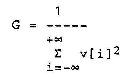
in bezug auf alle oder möglichst viele Spreizsequenzen gegebener Länge L maximal ist.An optimal or at least relatively optimal spreading sequence s [.] Is determined such that the process gain G, defined by the inverse of the energy of the associated inverse filter:
with respect to all or as many spreading sequences of given length L as possible.
Eine Möglichkeit um sicherzustellen, dass die minimalen zeitlichen Abstände eingehalten werden, besteht darin, über einen separaten Kanal Synchronisationssignale an die Teilnehmer des Uebertragungssystems zu übertragen.One way to ensure that the minimum time intervals are observed is to transmit synchronization signals to the participants in the transmission system via a separate channel.
Das erfindungsgemässe Verfahren eignet sich gut für Mobilfunksysteme. Ein Beispiel stellt der mikrozellulare Mobilfunk dar, wo sich die mobilen Teilnehmerstationen in einem Umkreis von typischerweise mehreren Metern bis maximal etwa 100 Metern einer Basisstation bewegen.The method according to the invention is well suited for mobile radio systems. One example is microcellular mobile radio, where the mobile subscriber stations move within a radius of typically several meters to a maximum of about 100 meters of a base station.
Aus der Gesamtheit der abhängigen Patentansprüche ergeben sich weitere vorteilhafte Ausführungsformen.Further advantageous embodiments result from the totality of the dependent claims.
Nachfolgend soll die Erfindung anhand von Ausführungsbeispielen und im Zusammenhang mit den Zeichnungen näher erläutert werden. Es zeigen:
- Fig. 1
- eine Darstellung der Synchronisation verschiedener Datenströme;
- Fig. 2
- eine schematische Darstellung des mit dem Inversfilter gefilterten Empfangssignals; und
- Fig. 3a,b
- ein Blockschaltbild eines erfindungsgemässen Mobilfunksystems.
- Fig. 1
- a representation of the synchronization of different data streams;
- Fig. 2
- a schematic representation of the received signal filtered with the inverse filter; and
- 3a, b
- a block diagram of an inventive mobile radio system.
Die in den Zeichnungen verwendeten Bezugszeichen und deren Bedeutung sind in der Bezeichnungsliste zusammenfassend aufgelistet. Grundsätzlich sind in den Figuren gleiche Teile mit gleichen Bezugszeichen versehen.The reference symbols used in the drawings and their meaning are summarized in the list of designations. In principle, the same parts are provided with the same reference symbols in the figures.
Fig. 1 veranschaulicht das Prinzip der Erfindung. Das Ziel des erfindungsgemässen Verfahrens besteht darin, mehrere separate Datenströme {B1,m}, {B2,m}, {B3,m}, m = 0, 1, 2, ..., gleichzeitig zu übertragen. Die Uebertragung soll dabei im gleichen HF-Bereich erfolgen. Typischerweise werden also mehrere Sender ihre Datenströme einer Trägerschwingung aufmodulieren, deren Frequenz für alle die selbe ist.Fig. 1 illustrates the principle of the invention. The aim of the method according to the invention is to transmit several separate data streams {B 1, m }, {B 2, m }, {B 3, m }, m = 0, 1, 2, ... simultaneously. The transmission should take place in the same HF range. Typically, several transmitters will modulate their data streams onto a carrier oscillation, the frequency of which is the same for all.
Die Datenströme {B1,m}, {B2,m}, {B3,m} beinhalten digitale (z.B. binäre) Daten in Form von Symbolen B1,m, B2,m, B3,m, welche im jeweiligen Datenstrom mit einer vorgegebenen Symboldauer T auftreten. Die einzelnen Datenströme {B1,m}, {B2,m}, {B3,m} werden in an sich bekannter Weise gespreizt: Jedes Symbol B1,m, B1,m+1, B1,m+2, wird mit einer fest vorgegebenen, aperiodischen Spreizsequenz s[i], i = 0..L, der Länge L multipliziert. Die Spreizsequenz besteht also aus L "Chips" mit einer Chipdauer TC = T/L. Das Resultat dieses Uebergangs von T auf T/L ist ein DSSS-Signal {B1,ms[.]}.The data streams {B 1, m }, {B 2, m }, {B 3, m } contain digital (eg binary) data in the form of symbols B 1, m , B 2, m , B 3, m , which in the each data stream occur with a predetermined symbol duration T. The individual data streams {B 1, m }, {B 2, m }, {B 3, m } are spread in a manner known per se: each symbol B 1, m , B 1, m + 1 , B 1, m + 2 , is multiplied by a fixed, aperiodic spreading sequence s [i], i = 0..L, of length L. The spreading sequence thus consists of L "chips" with a chip duration T C = T / L. The result of this transition from T to T / L is a DSSS signal {B 1, m s [.]}.
Jeder Datenstrom {B1,m}, {B2,m}, {B3,m} wird auf die beschriebene Weise zu einem entsprechenden DSSS-Signal (B1,ms[.]}, {B2,ms[.]}, {B3,ms[.]} verarbeitet. Die verschiedenen DSSS-Signale {B1,ms[.]}, {B2,ms[.]}, {B3,ms[.]} werden sodann zeitlich gegeneinander verschoben und zwar so, dass nie zwei zu verschiedenen Datenströmen gehörende Spreizintervalle zusammenfallen. Im vorliegenden Beispiel dürfen also die Spreizintervalle [B1,m], [B2,m] und [B3,m], welche alle von der Länge T sind, nie zum gleichen Zeitpunkt beginnen. Vielmehr müssen sie einen minimalen gegenseitigen zeitlichen Abstand Delta_T wahren. (Delta_T ist offensichtlich kleiner als die Länge T eines Zeitschlitzes.) Gemäss der in der Fig. 1 gezeigten Ausführungsform ist der zeitliche Abstand Delta_T für alle gleich gross (z.B. Delta_T = T/K; K = Anzahl Benützer). Das zweite DSSS-Signal {B2,ms[.]} weist also eine Verschiebung Delta_T gegenüber dem ersten DSSS-Signal {B1,ms[.]} auf. Das dritte DSSS-Signal {B3,ms[.]} ist um Delta_T gegenüber dem zweiten {B2,ms[.]} und um 2 Delta_T gegenüber dem ersten verzögert {B1,ms[.]}.Each data stream {B 1, m }, {B 2, m }, {B 3, m } becomes a corresponding DSSS signal (B 1, m s [.]}, {B 2, m s [.]}, {B 3, m s [.]} The various DSSS signals {B 1, m s [.]}, {B 2, m s [.]}, {B 3, m s [.]} are then shifted in time in such a way that two spreading intervals belonging to different data streams never coincide, so in the present example the spreading intervals [B 1, m ], [B 2, m ] and [B 3, m ] , all of which are of length T, never begin at the same time, but rather must maintain a minimum mutual time interval Delta_T (Delta_T is obviously smaller than the length T of a time slot.) According to the embodiment shown in FIG The time interval Delta_T is the same for everyone (eg Delta_T = T / K; K = number of users) The second DSSS signal {B 2, m s [.]} thus shows a shift in Delta_T compared to the first DSSS signal {B 1 , m s [.]}. The third te DSSS signal {B 3, m s [.]} is delayed by Delta_T compared to the second {B 2, m s [.]} and by 2 Delta_T compared to the first {B 1, m s [.]}.
Bei der Uebertragung überlagern sich die zu verschiedenen Datenströmen gehörenden DSSS-Signale {B1,ms[.]}, {B2,ms[.]}, {B3,ms[.]}. Ein Empfänger, der an einen bestimmten der Datenströme interessiert ist, muss diesen also zuerst aus dem Empfangssignal herausfiltern. Gemäss der Erfindung geschieht dies mit einem approximierten Inversfilter. Beim angestrebten idealen Inversfilter handelt es sich um ein bezüglich der Spreizsequenz inverses Filter. Dieses hat die Eigenschaft, dass es auf die vorgegebene Spreizsequenz als solche mit einer reinen Kronecker-Delta-Sequenz δ[k] antwortet. Dies soll im folgenden näher erläutert werden.During the transmission, the DSSS signals {B 1, m s [.]}, {B 2, m s [.]}, {B 3, m s [.]} Belonging to different data streams overlap. A receiver who is interested in a specific one of the data streams must therefore first filter this out of the received signal. According to the invention, this is done with an approximate inverse filter. The ideal inverse filter sought is an inverse filter with regard to the spreading sequence. This has the property that it responds to the specified spreading sequence as such with a pure Kronecker delta sequence δ [k]. This will be explained in more detail below.
Der Empfänger unterscheidet sich von einem bekannten DSSS-Empfänger also durch die Verwendung eines approximierten Inversfilters, anstelle eines Matched Filters.The receiver differs from a known DSSS receiver by the use of an approximate inverse filter instead of a matched filter.
Das Matched Filter, dessen Koeffizienten v[k] also gegeben wären gemäss v[k] = s[-i]*, ermittelt im wesentlichen eine Korrelationsfunktion der Spreizsequenz. Diese hat ein Maximum bei relativer zeitlicher Verschiebung um Null Abtastwerte. Um das Maximum gruppieren sich mehrere Nebenspitzen. Für Verschiebungen grösser als L Abtastwerte verschwindet die Korrelationsfunktion, da die Spreizsequenz selbst die endliche Länge L hat.The matched filter, whose coefficients v [k] would therefore be given according to v [k] = s [-i] *, essentially determines a correlation function of the spreading sequence. This has a maximum with a relative time shift of zero samples. Several secondary peaks are grouped around the maximum. The correlation function disappears for displacements greater than L samples, since the spreading sequence itself has the finite length L.
Das Inversfilter hat eine ganz andere Wirkung. Seine Antwort auf die Spreizsequenz als solche produziert eine Kronecker-Delta-Sequenz. Eine solche Sequenz zeichnet sich bekanntlich dadurch aus, dass sie nur einen von Null verschiedenen Abtastwert hat.The inverse filter has a completely different effect. His response to the spreading sequence as such produces a Kronecker delta sequence. As is known, such a sequence is distinguished by the fact that it has only one sample value that is different from zero.
In der Praxis lässt sich eine reine Kronecker-Delta-Sequenz nur näherungsweise realisieren, da sonst das Inversfilter unendlich viele Filterkoeffizienten v[k] aufweisen müsste.In practice, a pure Kronecker delta sequence can only be realized approximately, since otherwise the inverse filter would have to have an infinite number of filter coefficients v [k].
Deshalb wird die Impulsantwort des Filters auf eine Länge -M₁ ≦ k ≦ L+M₂ begrenzt. Ausserhalb dieses Fensters sind die Filterkoeffizienten v[k] identisch Null. Die von Null verschiedenen Filterkoeffizienten v[k] werden gemäss der Erfindung so gewählt, dass bei Anregung des Filters durch die Spreizsequenz das resultierende Ausgangssignal die Kronecker-Delta-Sequenz möglichst gut annähert.Therefore, the impulse response of the filter is limited to a length -M₁ ≦ k ≦ L + M₂. Outside this window, the filter coefficients v [k] are identical to zero. The filter coefficients v [k] other than zero are selected according to the invention such that when the filter is excited by the spreading sequence, the resulting output signal approximates the Kronecker delta sequence as closely as possible.
Wie aus der weiter oben zitierten, zeitgleichen Anmeldung EP-A-0 486 833 von F. Neeser et al. hervorgeht, gibt es für die Approximation drei bevorzugte Ausführungsformen:
- 1. Abschneiden des idealen Filters (Truncation).
- 2. Least Square-Approximation der Kronecker-Delta-Sequenz.
- 3. Maximales Peak/Off Peak-Verhältnis
- 1. Cutting off the ideal filter (truncation).
- 2. Least square approximation of the Kronecker delta sequence.
- 3. Maximum peak / off peak ratio
Weil die Koeffizienten v[k] des idealen Inversfilters im Fall einer geeignet ausgewählten Spreizsequenz für grosse k exponentiell zerfallen, lassen sich auch mit Filtern vernünftiger Länge schon ziemlich gute Resultate erreichen. Gemäss einer vorteilhaften Ausführungsform gehorchen die Koeffizienten v[k] des Inversfilters folgender Beziehung:
k = -M₁ ... L+M₂,
v[k] = 0, für k < -M₁ und k > L+M₂.Because the coefficients v [k] of the ideal inverse filter decay exponentially in the case of a suitably selected spreading sequence for large k, reasonably good results can also be achieved with filters of reasonable length. According to an advantageous embodiment, the coefficients v [k] of the inverse filter obey the following relationship:
k = -M₁ ... L + M₂,
v [k] = 0, for k <-M₁ and k> L + M₂.
Für ![]()
![]()
Ein derart ausgelegtes Filter ist als solches aus der Veröffentlichung von Jürg Ruprecht "Maximum-Likelihood Estimation of Multipath Channels", Diss. ETH Nr. 8789, Zürich 1989, Hartung-Gorre Verlag, bekannt. Dort ist auch gezeigt worden, dass die Koeffizienten für grosse k exponentiell zerfallen und infolgedessen die Truncation durchaus gute Resultate liefert.Such a filter is known as such from the publication by Jürg Ruprecht "Maximum Likelihood Estimation of Multipath Channels", Diss. ETH No. 8789, Zurich 1989, Hartung-Gorre Verlag. It was also shown there that the coefficients for large k decay exponentially and, as a result, the truncation delivers very good results.
Bei der Least Square-Approximation antwortet das approximierte Inversfilter bei Anregung durch die vorgegebene Spreizsequenz s[.] als solche mit einer Ausgangssequenz, die die Kronecker-Delta-Sequenz im Sinn der kleinsten Fehlerquadrate annähert.In the least square approximation, the approximated inverse filter responds when excited by the specified spreading sequence s [.] As such with an output sequence which approximates the Kronecker delta sequence in the sense of the smallest error squares.
Bei der dritten Approximation hat die Ausgangssequenz im genannten Fall ein maximales Peak/Off Peak-Verhältnis. D.h. der grösste Nebenpeak wird im Verhältnis zum Hauptpeak so klein wie möglich gemacht. Es handelt sich hier um eine angenäherte Realisierung des unendlich grossen Peak/Off Peak-Verhältnisses einer Kronecker-Delta-Sequenz.In the third approximation, the output sequence has a maximum peak / off peak ratio in the case mentioned. I.e. the largest secondary peak is made as small as possible in relation to the main peak. This is an approximate realization of the infinitely large peak / off peak ratio of a Kronecker delta sequence.
Eine wichtige Eigenschaft des Inversfilters liegt ausserdem darin, dass die Nebenspitzen, die mathematisch mit dem sog. Peak/off Peak-Verhältnis (POP ratio) quantitativ erfasst werden können, bei geeigneter Wahl der Spreizsequenz sehr klein gehalten werden können gegenüber dem Hauptimpuls. Es empfiehlt sich deshalb aus den Spreizsequenzen gegebener Länge diejenige mit dem grössten POP-Verhältnis zu wählen.Another important property of the inverse filter is that the secondary peaks, which can be quantitatively recorded mathematically with the so-called peak / off peak ratio (POP ratio), can be kept very small compared to the main pulse with a suitable choice of the spreading sequence. It is therefore advisable to choose the one with the largest POP ratio from the spreading sequences of a given length.
Wenn nun nicht die Spreizsequenz als solche, sondern das Empfangssignal mit einem Inversfilter gefiltert wird, dann hat dies zur Folge, dass ein Signal entsteht, das in periodisch wiederkehrende Zeitschlitze aufgeteilt werden kann, wobei jeder Zeitschlitz die Information über ein Symbol beinhaltet. Die Länge eines Zeitschlitzes entspricht der zeitlichen Verschiebung der verschiedenen entsprechenden DSSS-Signale {B1,ms[.]}, {B2,ms[.]}, {B3,ms[.]} in den Sendern. Um einen bestimmten Datenstrom zu detektieren, müssen also nur die entsprechenden Zeitschlitze ausgewertet werden.If, instead of the spreading sequence as such, the received signal is filtered with an inverse filter, this has the consequence that a signal is produced which can be divided into periodically recurring time slots, each time slot containing information about a symbol. The length of a time slot corresponds to the time shift of the various corresponding DSSS signals {B 1, ms [.]}, {B 2, ms [.]}, {B 3, ms [.]} In the transmitters. To detect a certain data stream, only the corresponding time slots need to be evaluated.
Fig. 2 zeigt beispielhaft einen Signalverlauf Y[k] am Ausgang des Inversfilters. Mit I₁ ,..., I₆ sind die Zeitschlitze bezeichnet. Sie sind im vorliegenden Fall von der Länge Delta_T (vgl. Fig. 1). Die um ein Zeitintervall T (Symboldauer) voneinander beabstandeten Zeitschlitze gehören jeweils zum selben Datenstrom. Bei K (hier K = 3) verschiedenen Datenströmen beinhalten also die jeweils K-ten (hier 3-ten) Zeitschlitze I₁, I₄, ..., resp. I₂, I₅, ..., resp. I₃, I₆, ..., die Information ein und desselben Datenstroms.2 shows an example of a signal curve Y [k] at the output of the inverse filter. With I₁, ..., I₆ the time slots are designated. In the present case, they are of the length Delta_T (cf. FIG. 1). The time slots spaced apart by a time interval T (symbol duration) each belong to the same data stream. At K (here K = 3) different Data streams thus contain the respective Kth (here 3rd) time slots I₁, I₄, ..., respectively. I₂, I₅, ..., respectively. I₃, I₆, ..., the information of the same data stream.
Bevor die Weiterverarbeitung des Signals aus einander entsprechenden Zeitschlitzen beschrieben wird, ist etwas über die Signalübertragung vorauszuschicken.Before the further processing of the signal from corresponding time slots is described, something has to be said about the signal transmission.
In einem Mobilfunksystem beispielsweise stammen die verschiedenen Datenströme von verschiedenen Teilnehmern. Bei der Uebertragung der DSSS-Signale von den mobilen Stationen zur Basisstation werden die Signale entsprechend dem zugehörigen Kanal hk(t), k = 1..K, verformt. In der Regel werden also die verschiedenen DSSS-Signale unterschiedlich verändert.In a mobile radio system, for example, the different data streams come from different subscribers. When the DSSS signals are transmitted from the mobile stations to the base station, the signals are deformed in accordance with the associated channel h k (t), k = 1..K. As a rule, the different DSSS signals are changed differently.
Oben wurde erläutert, dass die Systemantwort des Inversfilters auf die Spreizsequenz als solche im wesentlichen eine Kronecker-Delta-Sequenz ist. Ein unverformtes DSSS-Signal produziert am genannten Filterausgang eine Folge von Pulsen. Die Pulse haben einen zeitlichen Abstand T (Symboldauer) und sind entsprechend dem jeweiligen Symbolwert des Datenstroms gewichtet.It was explained above that the system response of the inverse filter to the spreading sequence as such is essentially a Kronecker delta sequence. An undeformed DSSS signal produces a sequence of pulses at the filter output mentioned. The pulses have a time interval T (symbol duration) and are weighted in accordance with the respective symbol value of the data stream.
Die Verformung des DSSS-Signals durch den Kanal hat nun zur Folge, dass am Ausgang des Inversfilters anstelle gewichteter Pulse die mit einem Symbolwert multiplizierte (äquivalente zeitdiskrete) Uebertragungsfunktion hk[.] des Kanals hk(t) entsteht.The deformation of the DSSS signal by the channel now has the result that at the output of the inverse filter instead of weighted pulses, the transmission function h k [.] Of the channel h k (t) multiplied by a symbol value is created (equivalent time-discrete).
Das in Fig. 2 gezeigte Ausgangssignal Y[k] setzt sich also im Prinzip zusammen aus gewichteten Kanalstossantworten. Im Zeitschlitz I₁ hat Y[k] also im wesentlichen (d.h. abgesehen von Rauschanteilen) den Verlauf B1,mh₁, wobei B1,m den Symbolwert und h₁ die Kanalstossantwort des Kanals zwischen erstem Benutzer und dem Empfänger bezeichnen. Im Zeitschlitz I₄, der ebenfalls dem ersten Datenstrom zuzuordnen ist, entspricht das Ausgangssignal sinngemäss der mit dem nächsten Symbolwert des Datenstroms multiplizierten Kanalstossantwort: B1,m+1h₁. Analoges gilt für die übrigen Zeitschlitze I₂, I₅, ..., resp. I₃, I₆, ...The output signal Y [k] shown in FIG. 2 is therefore composed in principle of weighted channel impulse responses. In the time slot I 1, Y [k] has essentially (ie apart from noise components) the course B 1, m h 1, B 1, m denoting the symbol value and h 1 the channel shock response of the channel between the first user and the receiver. In the time slot I₄, which is also assigned to the first data stream, the output signal corresponds analogously to that with the next one Symbol value of the data stream multiplied channel impulse response: B 1, m + 1 h 1 . The same applies to the other time slots I₂, I₅, ..., respectively. I₃, I₆, ...
Das in Fig. 2 gezeigte Beispiel bezieht sich auf den binären Fall Bk,m = +/-1. Da in den Zeitschlitzen I₁ und I₄ die Polarität des Ausgangssignals Y[k] positiv ist, betragen die entsprechenden Symbolwerte: B1,m = +1, B1,m+1 = +1. Aus analogen Ueberlegungen ergibt sich: B2,m = +1, B2,m+1 = -1, B3,m = -1, B3,m+1 = +1.The example shown in FIG. 2 relates to the binary case B k, m = +/- 1. Since in the time slots I₁ and I₄ the polarity of the output signal Y [k] is positive, the corresponding symbol values are: B 1, m = +1, B 1, m + 1 = +1. Analogous considerations result in: B 2, m = +1, B 2, m + 1 = -1, B 3, m = -1, B 3, m + 1 = +1.
Zum Detektieren der Daten extrahiert also der Empfänger alle zusammengehörenden Zeitschlitze (d.h. für den k-ten Datenstrom jeweils die k-ten Zeitschlitze eines Rahmens aus K Zeitschlitzen), filtert dieses extrahierte Signal mit einem kanalangepassten Matched Filter (dessen Stossantwort bekanntlich h*[-.] ist), extrahiert den Realteil des resultierenden Signals und führt eine Schwellwertdetektion durch. Auf diese Weise werden die Symbole nach dem ML-Prinzip (ML = Maximum Likelihood) geschätzt.To detect the data, the receiver extracts all the associated time slots (ie for the kth data stream, the kth time slots of a frame from K time slots), filters this extracted signal with a channel-matched matched filter (whose shock response is known to be h * [-. ] is), extracts the real part of the resulting signal and performs a threshold detection. In this way, the symbols are estimated according to the ML principle (ML = maximum likelihood).
Die Einzelheiten zum ML-Detektor sind in der bereits erwähnten Anmeldung der Erfinder F. Neeser et al. zu entnehmen. Insbesondere ist dort auch ein Verfahren zum Schätzen der Koeffizienten des kanalangepassten Matched Filters h*[-.] beschrieben, das auch bei der vorliegenden Erfindung eingesetzt werden kann.The details of the ML detector are in the aforementioned application by the inventor F. Neeser et al. refer to. In particular, there is also described a method for estimating the coefficients of the channel-matched matched filter h * [-.], Which can also be used in the present invention.
Gemäss einer vorteilhaften Ausführungsform ist die zeitliche Verschiebung Delta_T der zu verschiedenen Datenströmen gehörenden Spreizsequenzintervalle grösser ist als die Dauer der Stossantwort eines für die Uebertragung des entsprechenden DSSS-Signals verwendeten Kanals. Dadurch lassen sich die einzelnen Benutzer klar voneinander trennen, weil die zu verschiedenen Datenströmen gehörenden Signalanteile im Empfangssignal sich in keiner Weise überlagern. Ausserdem ist es damit möglich, gemäss einer vorteilhaften Ausführungsform die Kanalstossantwort für jeden Uebertragungskanal mit dem Detektor zu schätzen.According to an advantageous embodiment, the time shift Delta_T of the spreading sequence intervals belonging to different data streams is greater than the duration of the burst response of a channel used for the transmission of the corresponding DSSS signal. As a result, the individual users can be clearly separated from one another because the signal components belonging to different data streams in the received signal do not overlap in any way. It is also possible, according to an advantageous embodiment estimate the channel shock response for each transmission channel with the detector.
Um möglichst viele Datenströme gleichzeitig übertragen zu können, d.h. um ein Uebertragungssystem mit möglichst grosser Kapazität realisieren zu können, ist es nötig, die zeitliche Verschiebung der DSSS-Signale so klein wie möglich zu halten.In order to be able to transmit as many data streams as possible, i.e. In order to be able to implement a transmission system with the largest possible capacity, it is necessary to keep the time shift of the DSSS signals as small as possible.
Die zeitliche Verschiebung sollte jedoch einen vorgegebenen minimalen Wert nicht unterschreiten, sonst kann das Empfangssignal nicht mehr entmultiplext werden. Diese untere Grenze entspricht vorzugsweise der längsten auftretenden Kanalstossantwort plus einer Chipdauer und ist für alle DSSS-Signale im wesentlichen die selbe.However, the time shift should not fall below a predetermined minimum value, otherwise the received signal can no longer be demultiplexed. This lower limit preferably corresponds to the longest occurring channel impulse response plus a chip duration and is essentially the same for all DSSS signals.
Am einfachsten ist es, wenn die zeitliche Verschiebung Delta_T ein für alle Mal festgelegt wird (z.B. bei der Implementation des Systems). Es besteht aber durchaus auch die Möglichkeit, sie den konkreten Umständen der Uebertragungskanäle anzupassen.It is easiest if the time shift Delta_T is set once and for all (e.g. when implementing the system). However, there is also the possibility of adapting them to the specific circumstances of the transmission channels.
Der Vorteil der Erfindung besteht darin, dass keine exakte Synchronisation erforderlich ist. In einem begrenzten Rahmen ist es deshalb durchaus denkbar, das erfindungsgemässe Mehrfachzugriffsverfahren im Sinn eines Aloha oder Slotted Aloha Verfahrens ("random access") weiterzubilden.The advantage of the invention is that exact synchronization is not required. Within a limited framework, it is therefore entirely conceivable to develop the multiple access method according to the invention in the sense of an Aloha or Slotted Aloha method ("random access").
Eine bevorzugte Alternative besteht darin, bei der Implementation neben dem gemeinsamen Datenkanal einen separaten Synchronisationskanal vorzusehen. Auf diesem Synchronisationskanal werden (z.B. durch die Basisstation) Synchronisationssignale für die Einhaltung der minimalen zeitlichen Abstände an die Teilnehmer des Uebertragungssystems abgegeben. Solche Zusatzkanäle werden z.B. auch bei TDMA-Systemen verwendet.A preferred alternative is to provide a separate synchronization channel in addition to the common data channel during the implementation. On this synchronization channel (e.g. by the base station) synchronization signals for compliance with the minimum time intervals are sent to the participants in the transmission system. Such additional channels are e.g. also used in TDMA systems.
Ein Freiheitsgrad, auf den bis jetzt noch nicht eingegangen worden ist, der aber für die Qualität des Uebertragungssystems durchaus von Bedeutung sein kann, ist die konkrete Wahl der Spreizsequenz. Gemäss einer vorteilhaften Ausführungsform der Erfindung ist die Spreizsequenz s[.] so festgelegt, dass der Prozessgewinn G, definiert durch die Inverse der Energie des zugehörigen Inversfilters:
in bezug auf möglichst viele, insbesondere alle Spreizsequenzen gleicher Länge maximal ist.A degree of freedom, which has not yet been discussed, but which may well be of importance for the quality of the transmission system, is the specific choice of Spreading sequence. According to an advantageous embodiment of the invention, the spreading sequence s [.] Is defined such that the process gain G, defined by the inverse of the energy of the associated inverse filter:
with respect to as many, in particular all, spreading sequences of the same length is maximal.
Bei kleinen Sequenzlängen L ist es möglich, alle möglichen Pulskombinationen einer bestimmten Länge systematisch auf den Prozessgewinn zu prüfen und dann die optimale Spreizsequenz auszuwählen. Bei grossen Längen (z.B. L = 100) ist dies bis jetzt aus Gründen der benötigten extrem grossen Rechenzeit noch nicht möglich, da schnelle systematische Suchalgorithmen fehlen. In der Praxis hilft man sich dann so, dass man eine beschränkte Klasse von Sequenzen mit tendenziell guten Eigenschaften auswählt und die Optimierung nur innerhalb dieser Klasse durchführt. Es handelt sich dann nur um eine relative Optimierung.With small sequence lengths L, it is possible to systematically check all possible pulse combinations of a certain length for the process gain and then to select the optimal spreading sequence. With long lengths (e.g. L = 100), this is not yet possible due to the extremely large computing time required, since fast systematic search algorithms are missing. In practice, one then helps one another by selecting a restricted class of sequences which tend to have good properties and only carrying out the optimization within this class. Then it is only a question of relative optimization.
Fig. 3a,b zeigt ein Blockschaltbild eines erfindungsgemässen Mobilfunksystems. Es umfasst eine Basisstation T₀ und K mobile Teilnehmerstationen T₁, ..., TK. Alle Stationen sind sowohl mit einem Sender- als auch mit einem Empfängerschaltkreis ausgestattet, um Zweiwegkommunikation zu ermöglichen. In Fig. 3a sind die Sender der Teilnehmerstationen T₁, ..., TK und der Empfänger der Basisstation T₀ und in Fig. 3b die Empfänger der Teilnehmerstationen T₁, ..., TK und der Sender der Basisstation T₀ gezeigt.3a, b shows a block diagram of a mobile radio system according to the invention. It includes a base station T₀ and K mobile subscriber stations T₁, ..., T K. All stations are equipped with both a transmitter and a receiver circuit to enable two-way communication. In Fig. 3a the transmitters of the subscriber stations T₁, ..., T K and the receiver of the base station T₀ and in Fig. 3b the receivers of the subscriber stations T₁, ..., T K and the transmitter of the base station T₀ are shown.
Der Sender der K-ten Teilnehmerstation TK beispielsweise umfasst einen Expander 1.K, der den Datenstrom {BK,m} zeitlich spreizt, indem vom Symbolintervall T auf das Chipintervall TC = T/L übergegangen wird (L = Anzahl Chips in der Spreizsequenz). Ein Verzögerungsglied 2.K bringt die erforderliche zeitliche Verschiebung (K-1)TC gegenüber den anderen Teilnehmern in den Datenstrom. Im Spreizsequenzgenerator 3.K wird die vorgegebene gemeinsame Spreizsequenz s[.] mit dem jeweils anliegenden Symbolwert multipliziert. Auf diese Weise wird das digitale DSSS-Signal erzeugt. Mit einem Impulsmodulator 4.K und einem Tiefpassfilter 5.K wird ein zeitkontinuierliches DSSS-Signal erzeugt, welches dann in einem konventionellen Modulator 6.K in an sich bekannter Weise einer Trägerschwingung aufmoduliert wird.The transmitter of the K-th subscriber station T K, for example, comprises an expander 1.K, which timed the data stream {B K, m } spreads by changing from the symbol interval T to the chip interval T C = T / L (L = number of chips in the spreading sequence). A delay element 2.K brings the required time shift (K-1) T C towards the other participants in the data stream. In the spreading sequence generator 3.K, the predetermined common spreading sequence s [.] Is multiplied by the symbol value present in each case. The digital DSSS signal is generated in this way. With a pulse modulator 4.K and a low-pass filter 5.K, a continuous-time DSSS signal is generated, which is then modulated onto a carrier oscillation in a conventional modulator 6.K.
Die einzelnen Teilnehmerstationen T₁,..., TK sind im Prinzip alle gleich. Im Betrieb unterscheiden sie sich nur durch den Delay, mit dem sie ihren Datenstrom versehen.The individual subscriber stations T₁, ..., T K are in principle all the same. In operation, they differ only in the delay with which they provide their data stream.
Bei der Uebertragung werden die Signale durch den jeweiligen Kanal h₁, h₂, ..., hK deformiert und verrauscht (additives weisses Gauss'sches Rauschen W(t)). Im Empfänger überlagern sich die Signale der verschiedenen Teilnehmerstationen (Σ).During the transmission, the signals are deformed and noisy through the
Der Empfänger der Basisstation T₀ demoduliert die Trägerschwingung (Demodulator 7), filtert den relevanten Frequenzbereich heraus (Filter 8) und tastet das gefilterte Signal mit der Chiprate 1/TC ab.The receiver of the base station T₀ demodulates the carrier oscillation (demodulator 7), filters out the relevant frequency range (filter 8) and samples the filtered signal at the
Gemäss einem wesentlichen Merkmal der Erfindung wird das Empfangssignal X[i] mit einem Inversfilter 9 gefiltert. Dadurch erhält man ein Ausgangssignal Y[k] mit den anhand von Fig. 2 erläuterten Eigenschaften.According to an essential feature of the invention, the received signal X [i] is filtered with an inverse filter 9. This gives an output signal Y [k] with the properties explained with reference to FIG. 2.
Eine Selektionsschaltung 10 extrahiert die zum selben Datenstrom gehörenden Zeitschlitze. Für jeden Datenstrom schliesst sich dann ein ML-Detektor 11.1, ..., 11.K an.A selection circuit 10 extracts the time slots belonging to the same data stream. An ML detector 11.1, ..., 11.K then follows for each data stream.
Fig. 3b veranschaulicht die umgekehrte Richtung der Datenübertragung. Die Basisstation T₀ verarbeitet parallel K Datenströme {Bk,m}, k = 1..K. Jeder wird gespreizt (Expander 12.1...12.K) und in einem Verzögerungsglied 13.k, k = 1..K, auf geeignete Weise mit einer zeitlichen Verschiebung (k-1)Delta_T, k = 1..K, versehen. Die verzögerten Signale werden in Spreizsequenzgeneratoren 14.1...14.K zu DSSS-Signalen verarbeitet. Eine Summierschaltung 15 überlagert die K DSSS-Signale zu einem digitalen Uebertragungssignal U(i). Dieses wird in an sich bekannter Weise mit einem Impulsmodulator 16 und einem Tiefpassfilter 17 zu einem zeitkontinuierlichen Signal U(t) verarbeitet. Ein Modulator 18 moduliert eine vorgegebene Trägerschwingung entsprechend dem zeitkontinuierlichen Signal U(t).3b illustrates the reverse direction of data transmission. The base station T₀ processes K data streams {B k, m }, k = 1..K in parallel. Each is spread (expander 12.1 ... 12.K) and provided in a delay element 13.k, k = 1..K, in a suitable manner with a time shift (k-1) Delta_T, k = 1..K. . The delayed signals are processed in spreading sequence generators 14.1 ... 14.K into DSSS signals. A summing
Bei der Uebertragung zur k-ten Teilnehmerstation Tk erfährt die modulierte Trägerschwingung eine Verformumg im Kanal hk und eine Beeinträchtigung durch ein additives weisses Gauss'sches Rauschen W(t).When transmitted to the k-th subscriber station T k , the modulated carrier oscillation undergoes deformation in the channel h k and is impaired by an additive white Gaussian noise W (t).
Die Teilnehmerstation Tk demoduliert die Trägerschwingung und filtert den gewünschten Frequenzbereich heraus (Demodulator 19, Filter 20). Das resultierende Empfangssignal Xk(t) wird mit einem ganzzahligen Vielfachen der Chiprate 1/TC abgetastet und dann mit dem Inversfilter 21 gefiltert. Das abgetastete Empfangssignal wird dadurch entspreizt. Eine Selektionsschaltung 22 extrahiert entsprechend dem erfindungsgemässen Verfahren die der Teilnehmerstation Tk zugewiesenen Zeitschlitze (z.B. immer den k-ten aus einem Rahmen von K Zeitschlitzen). Auf diese Weise wird ein Signal Yk gewonnen, aus welchem der Datenstrom (Bk,m mit einem Dach gekennzeichnet) mit einem ML-Detektor 23 geschätzt werden kann.The subscriber station T k demodulates the carrier oscillation and filters out the desired frequency range (demodulator 19, filter 20). The resulting received signal X k (t) is sampled with an integer multiple of the
Die Einzelheiten zum ML-Detektor 23 können der bereits mehrfach erwähnten zeitgleichen Anmeldung EP-A-0 486 833 (F. Neeser et al.) entnommen werden.The details of the ML detector 23 can be found in the simultaneous application EP-A-0 486 833 (F. Neeser et al.), Which has already been mentioned several times.
Während die Ueberlagerung bei der Uebertragung in Richtung Basisstation "automatisch" erfolgt (die von den verschiedenen Teilnehmern kommenden Signale überlagern sich physikalisch), so geschieht dies in umgekehrter Richtung "aktiv" d.h. auf elektronischer resp. schaltungstechnischer Ebene (Summierschaltung 15).While the overlay takes place "automatically" during the transmission in the direction of the base station (the signals coming from the different subscribers overlap physically), this is done in the opposite direction "actively", i.e. on electronic resp. circuit level (summing circuit 15).
Die im Zusammenhang mit dem erfindungsgemässen Verfahren beschriebenen verschiedenen Ausführungsformen können im Lichte der Beschreibung ohne weiteres schaltungstechnisch implementiert werden.The various embodiments described in connection with the method according to the invention can easily be implemented in terms of circuitry in the light of the description.
Abschliessend kann festgehalten werden, dass die Erfindung ein Mehrfachzugriffsverfahren schafft, das die Vorteile von TDMA und CDMA auf sich vereinigt. Insbesondere ist eine praktisch totale Trennung der Benutzer möglich, ohne dass die bei TDMA übliche Präzision der Synchronisation nötig wäre.In conclusion, it can be stated that the invention creates a multiple access method which combines the advantages of TDMA and CDMA. In particular, a practically total separation of users is possible without the need for the precision of synchronization that is customary with TDMA.
Claims (9)
- Multiple-access process for the simultaneous exchange of several data streams ({B1,m}, {B2,m}, {B3,m}) between several subscribers (T₀, ..., TK) of a transmission system, each of the various data streams ({B1,m}, {B2,m}, {B3,m}) being spread with the same spread sequence (s[.]) to form a corresponding DSSS signal (DSSS = Direct Sequence Spread Spectrum) and the various DSSS signals ({B1,ms[.]}, {B2,ms[.]}, {B3,ms[.]}) being superimposed during transmission to form a single received signal, characterised in that, in order to detect one of the various data streams ({B1,m}, {B2,m}, {B3,m}) in a receiver, the received signal is filtered in a filter (9, 21) which is reversed in relation to the common spread sequence (s[.]), and in that the superimposition is effected in such a manner that the spread sequence intervals (B1,mSi, B2,mSi, ...) belonging to various data streams ({B1,m}, {B2,m}, {B3,m}) are staggered relative to one another in time by a predetermined minimum value (Delta_T).
- Multiple-access process according to Claim 1, characterised in that the time stagger (Delta_T) of the spread sequence intervals (B1,mSi, B2,mSi, ...) belonging to various data streams ({B1,m}, {B2,m}, {B3,m}) is greater than a chip time (T₀) plus the duration of the impulse response of a channel (hk(t)) used for the transmission of the corresponding DSSS signal.
- Multiple-access process according to Claim 1 or 2, characterised in that the time stagger (Delta_T) with respect to adjacent spread sequence intervals (B1,mSi, B2,mSi, ...) is of substantially the same size for all spread sequence intervals (B1,mSi, B2,mSi, ...) belonging to various data streams ({B1,m}, {B2,m}, {B3,m}).
- Multiple-access process according to any one of Claims 1 to 3, characterised in that the reversed filter (9, 21) is so chosen that, when it is excited by the predetermined pulse sequence (s[.]) as such, it responds approximately with a Kronecker-Delta sequence (δ[k]) as starting sequence.
- Multiple-access process according to any one of Claims 1 to 4, characterised in that the coefficients v[k] of the reversed filter (9, 21) belonging to the spread sequence (s[.]) are chosen in accordance with one of the following three approximations, namely eithera) cut-off reversed filter, according to the formula

v[k] = 0 , for k < -M₁ and k > L+M₂ ; orb) smallest error squares,
the coefficients v[k], k = -M₁ ... L+M₂ being so determined that, when it is excited by the predetermined pulse sequence (s[.]) as such, the approximated reversed filter responds with a starting sequence which approximates the Kronecker-Delta sequence (δ[k]) in accordance with the smallest error squares; orc) maximum POP ratio,
the approximated reversed filter (9, 21) with a predetermined number of coefficients v[k], k = -M₁ ... L+M₂ responding when excited by the predetermined pulse sequence (s[.]) as such with a starting sequence which approximates the Kronecker-Delta sequence (δ[k]) in accordance with a maximum peak/off-peak ratio. - Multiple-access process according to any one of Claims 1 to 5, characterised in that the spread sequence (s[.]) is so determined that the process gain G, defined by the inverse of the energy of the associated reversed filter:

- Multiple-access process according to any one of Claims 1 to 6, characterised in that, in order to observe the minimum time intervals, synchronisation signals are transmitted to the subscribers (T₁, ..., TK) of the transmissionsystem via a separate channel.
- Mobile radiocommunication system for implementing the multiple-access process according to Claim 1, comprising at least one base station (T₀) and several subscriber stations (T₁, ..., TK) having transmitter/receiver circuit arrangements each of which has a circuit (3.1, ..., 3.K, 14.1, ..., 14.K) in order to spread each of the various data streams ({B1,m}, {B2,m}, {B3,m}) with the same spread sequence (s[.]) to form a corresponding DSSS signal, and a circuit (15) in the base station (T₀) in order to superimpose the various DSSS signals ({B1,ms[.]}, {B2,ms[.]}, {B3,ms[.]}) for the transmission to form a single received signal, wherein, in order to detect one of the various data streams ({B1,m}, {B2,m}, {B3,m}), the receiver circuit arrangement has a reversed filter (9, 21) for filtering the received signal in reversed manner in relation to the common spread sequence, and wherein delay elements (2.1, ..., 2.K, 13.1, ..., 13.K) are provided which stagger relative to one another in time, by a predetermined minimum value (Delta_T), the spread sequence intervals (B1,mSi, B2,mSi, ...) belonging to various data streams ({B1,m}, {B2,m}, {B3,m}).
- Mobile radiocommunication system according to Claim 8, characterised in that the subscriber stations (T₁, ..., TK) and the base station (T₀) have means (18) for modulating a carrier oscillation in accordance with a given DSSS signal, the carrier oscillation being the same for all subscriber stations (T₁, ..., TK) and the base station (T₀).
Applications Claiming Priority (2)
| Application Number | Priority Date | Filing Date | Title |
|---|---|---|---|
| CH370290 | 1990-11-22 | ||
| CH3702/90 | 1990-11-22 |
Publications (2)
| Publication Number | Publication Date |
|---|---|
| EP0486834A1 EP0486834A1 (en) | 1992-05-27 |
| EP0486834B1 true EP0486834B1 (en) | 1995-11-22 |
Family
ID=4261690
Family Applications (1)
| Application Number | Title | Priority Date | Filing Date |
|---|---|---|---|
| EP91118102A Expired - Lifetime EP0486834B1 (en) | 1990-11-22 | 1991-10-24 | Multi-access method and mobile radiocommunication system implementing said multi-access method |
Country Status (5)
| Country | Link |
|---|---|
| US (1) | US5170412A (en) |
| EP (1) | EP0486834B1 (en) |
| JP (1) | JPH04351130A (en) |
| AT (1) | ATE130712T1 (en) |
| DE (1) | DE59106942D1 (en) |
Families Citing this family (65)
| Publication number | Priority date | Publication date | Assignee | Title |
|---|---|---|---|---|
| US5285469A (en) * | 1991-06-03 | 1994-02-08 | Omnipoint Data Corporation | Spread spectrum wireless telephone system |
| DE69331375T2 (en) * | 1992-11-04 | 2002-08-14 | Nippon Telegraph & Telephone | MOBILE COMMUNICATION SYSTEM WITH CODEMULTIPLEX MULTIPLE ACCESS |
| US5341395A (en) * | 1992-11-24 | 1994-08-23 | At&T Bell Laboratories | Data recovery technique for asynchronous CDMA systems |
| FI925472A (en) * | 1992-12-01 | 1994-06-02 | Nokia Mobile Phones Ltd | Data transfer procedure and system |
| US5345468A (en) * | 1992-12-16 | 1994-09-06 | At&T Bell Laboratories | Despreading technique for CDMA systems |
| WO1994021056A1 (en) * | 1993-03-05 | 1994-09-15 | Ntt Mobile Communications Network Inc. | Random access communication method by use of cdma, and system for mobile stations which use the method |
| FI933129A0 (en) * | 1993-07-08 | 1993-07-08 | Nokia Mobile Phones Ltd | DATAOEVERFOERINGSFOERFARANDE FOER ETT DIGITALT CELLULAERT MOBILTELEFONSYSTEM OCH ETT DIGITALT CELLULAERT MOBILTELEFONSYSTEM |
| US5537434A (en) * | 1993-10-25 | 1996-07-16 | Telefonaktiebolaget Lm Ericsson | Frequency hopping control channel in a radio communication system |
| US5436941A (en) * | 1993-11-01 | 1995-07-25 | Omnipoint Corporation | Spread spectrum spectral density techniques |
| US6088590A (en) | 1993-11-01 | 2000-07-11 | Omnipoint Corporation | Method and system for mobile controlled handoff and link maintenance in spread spectrum communication |
| US6005856A (en) | 1993-11-01 | 1999-12-21 | Omnipoint Corporation | Communication protocol for spread spectrum wireless communication system |
| IL111469A0 (en) * | 1993-11-01 | 1994-12-29 | Omnipoint Corp | Despreading/demodulating direct sequence spread spectrum signals |
| US6094575A (en) * | 1993-11-01 | 2000-07-25 | Omnipoint Corporation | Communication system and method |
| JP3003839B2 (en) * | 1993-11-08 | 2000-01-31 | エヌ・ティ・ティ移動通信網株式会社 | CDMA communication method and apparatus |
| FR2713418B1 (en) * | 1993-11-30 | 1995-12-29 | Thomson Csf | Packet transmission method and transmitter and receiver using this method. |
| JP2636712B2 (en) * | 1993-12-08 | 1997-07-30 | 日本電気株式会社 | Mobile communication device |
| JP2734952B2 (en) * | 1993-12-16 | 1998-04-02 | 日本電気株式会社 | CDMA base station receiver |
| JPH07245597A (en) * | 1994-03-02 | 1995-09-19 | Pioneer Electron Corp | Spread spectrum communication method and transmitter-receiver |
| JP3302168B2 (en) * | 1994-04-05 | 2002-07-15 | 株式会社東芝 | Mobile radio communication system |
| FR2721784B1 (en) * | 1994-06-24 | 1996-07-19 | Thomson Csf | Method, transmitter and receiver for the transmission of information in packets. |
| US5692007A (en) | 1994-09-09 | 1997-11-25 | Omnipoint Corporation | Method and apparatus for differential phase encoding and decoding in spread-spectrum communication systems with continuous-phase modulation |
| US5963586A (en) | 1994-09-09 | 1999-10-05 | Omnipoint Corporation | Method and apparatus for parallel noncoherent correlation of a spread spectrum signal |
| US5881100A (en) | 1994-09-09 | 1999-03-09 | Omnipoint Corporation | Method and apparatus for coherent correlation of a spread spectrum signal |
| US5832028A (en) | 1994-09-09 | 1998-11-03 | Omnipoint Corporation | Method and apparatus for coherent serial correlation of a spread spectrum signal |
| US5610940A (en) | 1994-09-09 | 1997-03-11 | Omnipoint Corporation | Method and apparatus for noncoherent reception and correlation of a continous phase modulated signal |
| US5627856A (en) | 1994-09-09 | 1997-05-06 | Omnipoint Corporation | Method and apparatus for receiving and despreading a continuous phase-modulated spread spectrum signal using self-synchronizing correlators |
| US5856998A (en) | 1994-09-09 | 1999-01-05 | Omnipoint Corporation | Method and apparatus for correlating a continuous phase modulated spread spectrum signal |
| US5754584A (en) | 1994-09-09 | 1998-05-19 | Omnipoint Corporation | Non-coherent spread-spectrum continuous-phase modulation communication system |
| US5680414A (en) | 1994-09-09 | 1997-10-21 | Omnipoint Corporation | Synchronization apparatus and method for spread spectrum receiver |
| US5757847A (en) | 1994-09-09 | 1998-05-26 | Omnipoint Corporation | Method and apparatus for decoding a phase encoded signal |
| JP3215018B2 (en) * | 1994-09-09 | 2001-10-02 | 三菱電機株式会社 | Mobile communication system |
| US5953370A (en) | 1994-09-09 | 1999-09-14 | Omnipoint Corporation | Apparatus for receiving and correlating a spread spectrum signal |
| US5648982A (en) | 1994-09-09 | 1997-07-15 | Omnipoint Corporation | Spread spectrum transmitter |
| US5659574A (en) | 1994-09-09 | 1997-08-19 | Omnipoint Corporation | Multi-bit correlation of continuous phase modulated signals |
| US5754585A (en) | 1994-09-09 | 1998-05-19 | Omnipoint Corporation | Method and apparatus for serial noncoherent correlation of a spread spectrum signal |
| US5629956A (en) | 1994-09-09 | 1997-05-13 | Omnipoint Corporation | Method and apparatus for reception and noncoherent serial correlation of a continuous phase modulated signal |
| US5625642A (en) * | 1994-10-11 | 1997-04-29 | Lucent Technologies Inc. | Spread-response precoding system having signature sequences longer than the inter-symbol time interval |
| US5570351A (en) * | 1994-10-11 | 1996-10-29 | Lucent Technologies Inc. | Multi-user communication system employing spread signatures |
| US5742583A (en) | 1994-11-03 | 1998-04-21 | Omnipoint Corporation | Antenna diversity techniques |
| FI97583C (en) | 1995-02-02 | 1997-01-10 | Nokia Mobile Phones Ltd | Procedure for data communication, transmitters and receivers |
| US5784403A (en) * | 1995-02-03 | 1998-07-21 | Omnipoint Corporation | Spread spectrum correlation using saw device |
| US5627855A (en) * | 1995-05-25 | 1997-05-06 | Golden Bridge Technology, Inc. | Programmable two-part matched filter for spread spectrum |
| US5959980A (en) * | 1995-06-05 | 1999-09-28 | Omnipoint Corporation | Timing adjustment control for efficient time division duplex communication |
| US5802046A (en) * | 1995-06-05 | 1998-09-01 | Omnipoint Corporation | Efficient time division duplex communication system with interleaved format and timing adjustment control |
| US5689502A (en) * | 1995-06-05 | 1997-11-18 | Omnipoint Corporation | Efficient frequency division duplex communication system with interleaved format and timing adjustment control |
| US5745484A (en) | 1995-06-05 | 1998-04-28 | Omnipoint Corporation | Efficient communication system using time division multiplexing and timing adjustment control |
| US6041046A (en) * | 1995-07-14 | 2000-03-21 | Omnipoint Corporation | Cyclic time hopping in time division multiple access communication system |
| US5960028A (en) * | 1995-08-11 | 1999-09-28 | Sharp Kabushiki Kaisha | Spread spectrum communication system |
| US6108364A (en) * | 1995-08-31 | 2000-08-22 | Qualcomm Incorporated | Time division duplex repeater for use in a CDMA system |
| US5844894A (en) * | 1996-02-29 | 1998-12-01 | Ericsson Inc. | Time-reuse partitioning system and methods for cellular radio telephone systems |
| US5606548A (en) * | 1996-04-16 | 1997-02-25 | Nokia Mobile Phones Limited | Mobile terminal having improved digital control channel (DCCH) search procedure |
| JP2800891B2 (en) * | 1996-12-17 | 1998-09-21 | 日本電気株式会社 | CDMA multi-code transmission device |
| US6282228B1 (en) * | 1997-03-20 | 2001-08-28 | Xircom, Inc. | Spread spectrum codes for use in communication |
| US6151354A (en) * | 1997-12-19 | 2000-11-21 | Rockwell Science Center | Multi-mode, multi-band, multi-user radio system architecture |
| US7031371B1 (en) | 2000-09-25 | 2006-04-18 | Lakkis Ismail A | CDMA/TDMA communication method and apparatus for wireless communication using cyclic spreading codes |
| US7317756B2 (en) | 2001-12-06 | 2008-01-08 | Pulse-Link, Inc. | Ultra-wideband communication apparatus and methods |
| US7406647B2 (en) | 2001-12-06 | 2008-07-29 | Pulse-Link, Inc. | Systems and methods for forward error correction in a wireless communication network |
| US7450637B2 (en) | 2001-12-06 | 2008-11-11 | Pulse-Link, Inc. | Ultra-wideband communication apparatus and methods |
| US7391815B2 (en) | 2001-12-06 | 2008-06-24 | Pulse-Link, Inc. | Systems and methods to recover bandwidth in a communication system |
| US7403576B2 (en) | 2001-12-06 | 2008-07-22 | Pulse-Link, Inc. | Systems and methods for receiving data in a wireless communication network |
| US7483483B2 (en) | 2001-12-06 | 2009-01-27 | Pulse-Link, Inc. | Ultra-wideband communication apparatus and methods |
| US8045935B2 (en) | 2001-12-06 | 2011-10-25 | Pulse-Link, Inc. | High data rate transmitter and receiver |
| WO2007008431A2 (en) * | 2005-07-06 | 2007-01-18 | The Penn State Research Foundation | A networked multiband waveguide intrusion detection and localization sensor |
| US10623468B1 (en) | 2014-05-30 | 2020-04-14 | Mbr Innovations Llc | Systems and methods for simultaneous electronic file exchange |
| US10957445B2 (en) | 2017-10-05 | 2021-03-23 | Hill-Rom Services, Inc. | Caregiver and staff information system |
-
1991
- 1991-10-24 DE DE59106942T patent/DE59106942D1/en not_active Expired - Fee Related
- 1991-10-24 EP EP91118102A patent/EP0486834B1/en not_active Expired - Lifetime
- 1991-10-24 AT AT91118102T patent/ATE130712T1/en not_active IP Right Cessation
- 1991-11-15 JP JP3353521A patent/JPH04351130A/en active Pending
- 1991-11-21 US US07/795,478 patent/US5170412A/en not_active Expired - Fee Related
Also Published As
| Publication number | Publication date |
|---|---|
| ATE130712T1 (en) | 1995-12-15 |
| EP0486834A1 (en) | 1992-05-27 |
| DE59106942D1 (en) | 1996-01-04 |
| JPH04351130A (en) | 1992-12-04 |
| US5170412A (en) | 1992-12-08 |
Similar Documents
| Publication | Publication Date | Title |
|---|---|---|
| EP0486834B1 (en) | Multi-access method and mobile radiocommunication system implementing said multi-access method | |
| DE69815105T2 (en) | MOBILE STATION SYNCHRONIZATION IN A SPREADING SPECTRUM MESSAGE TRANSMISSION SYSTEM | |
| DE69433336T2 (en) | CDMA COMMUNICATION METHOD WITH SELECTIVE ACCESS AND ARRANGEMENT FOR MOBILE STATIONS IN WHICH THIS METHOD IS APPLIED | |
| DE69834603T2 (en) | Frame structure for a multi-bit-rate CDMA communication system | |
| DE60016664T2 (en) | Method for collectively collecting a set of CDMA codes | |
| EP0211460B1 (en) | Digital radio transmission method | |
| EP0361299B1 (en) | Digital radio transmission system for a cellular network using the spread spectrum technique | |
| EP1006670B1 (en) | Wireless Network | |
| DE3527329A1 (en) | DIGITAL RADIO TRANSMISSION SYSTEM WITH VARIABLE TIME SLOT DURATION OF TIME SLOTS IN TIME MULTIPLEX FRAME | |
| EP0151280B1 (en) | Time division multiplex method for a digital cellular radio system | |
| DE60011566T2 (en) | Receiver for a CDMA mobile communication system | |
| DE60035028T2 (en) | SPREIZSPEKTRUMKOMMUNIKATIONSGERÄT | |
| DE19747367C2 (en) | Method and arrangement for the transmission of data via a radio interface in a radio communication system | |
| EP1021003A2 (en) | Wireless Network | |
| DE10038187B4 (en) | Method for transmitting in non-orthogonal physical channels in the communication system | |
| EP0967742A2 (en) | Wireless Network | |
| DE69828250T2 (en) | Digital direct sequence spread spectrum message transmission with noise generation | |
| EP2689535B1 (en) | Method and decoder for depspreading of data signals which are spread with walsh sequences | |
| DE60310067T2 (en) | Data estimation based on segmental channel equalization | |
| DE69934883T2 (en) | REDUCTION OF FLOW DENSITY IN AN OCDMA SATELLITE COMMUNICATION SYSTEM | |
| DE69835816T2 (en) | Method and device for receiving | |
| DE60038063T2 (en) | Reduction of computational complexity in joint detection | |
| DE19625859C1 (en) | Noise measurement for CDMA reception arrangement | |
| EP2412104B1 (en) | Converter for perfect despreading of orthogonal cdma sequences | |
| DE69936622T2 (en) | Transmission method in a radio communication system with multiple access |
Legal Events
| Date | Code | Title | Description |
|---|---|---|---|
| PUAI | Public reference made under article 153(3) epc to a published international application that has entered the european phase |
Free format text: ORIGINAL CODE: 0009012 |
|
| 17P | Request for examination filed |
Effective date: 19920224 |
|
| AK | Designated contracting states |
Kind code of ref document: A1 Designated state(s): AT CH DE FR GB LI SE |
|
| 17Q | First examination report despatched |
Effective date: 19940530 |
|
| GRAA | (expected) grant |
Free format text: ORIGINAL CODE: 0009210 |
|
| AK | Designated contracting states |
Kind code of ref document: B1 Designated state(s): AT CH DE FR GB LI SE |
|
| REF | Corresponds to: |
Ref document number: 130712 Country of ref document: AT Date of ref document: 19951215 Kind code of ref document: T |
|
| ET | Fr: translation filed | ||
| REF | Corresponds to: |
Ref document number: 59106942 Country of ref document: DE Date of ref document: 19960104 |
|
| GBT | Gb: translation of ep patent filed (gb section 77(6)(a)/1977) |
Effective date: 19960217 |
|
| PLBE | No opposition filed within time limit |
Free format text: ORIGINAL CODE: 0009261 |
|
| STAA | Information on the status of an ep patent application or granted ep patent |
Free format text: STATUS: NO OPPOSITION FILED WITHIN TIME LIMIT |
|
| 26N | No opposition filed | ||
| REG | Reference to a national code |
Ref country code: GB Ref legal event code: IF02 |
|
| PGFP | Annual fee paid to national office [announced via postgrant information from national office to epo] |
Ref country code: AT Payment date: 20020905 Year of fee payment: 12 |
|
| PGFP | Annual fee paid to national office [announced via postgrant information from national office to epo] |
Ref country code: FR Payment date: 20020906 Year of fee payment: 12 |
|
| PGFP | Annual fee paid to national office [announced via postgrant information from national office to epo] |
Ref country code: GB Payment date: 20020916 Year of fee payment: 12 |
|
| PGFP | Annual fee paid to national office [announced via postgrant information from national office to epo] |
Ref country code: CH Payment date: 20020917 Year of fee payment: 12 |
|
| PGFP | Annual fee paid to national office [announced via postgrant information from national office to epo] |
Ref country code: SE Payment date: 20020918 Year of fee payment: 12 |
|
| PGFP | Annual fee paid to national office [announced via postgrant information from national office to epo] |
Ref country code: DE Payment date: 20020924 Year of fee payment: 12 |
|
| PG25 | Lapsed in a contracting state [announced via postgrant information from national office to epo] |
Ref country code: GB Free format text: LAPSE BECAUSE OF NON-PAYMENT OF DUE FEES Effective date: 20031024 Ref country code: AT Free format text: LAPSE BECAUSE OF NON-PAYMENT OF DUE FEES Effective date: 20031024 |
|
| PG25 | Lapsed in a contracting state [announced via postgrant information from national office to epo] |
Ref country code: SE Free format text: LAPSE BECAUSE OF NON-PAYMENT OF DUE FEES Effective date: 20031025 |
|
| PG25 | Lapsed in a contracting state [announced via postgrant information from national office to epo] |
Ref country code: LI Free format text: LAPSE BECAUSE OF NON-PAYMENT OF DUE FEES Effective date: 20031031 Ref country code: CH Free format text: LAPSE BECAUSE OF NON-PAYMENT OF DUE FEES Effective date: 20031031 |
|
| PG25 | Lapsed in a contracting state [announced via postgrant information from national office to epo] |
Ref country code: DE Free format text: LAPSE BECAUSE OF NON-PAYMENT OF DUE FEES Effective date: 20040501 |
|
| EUG | Se: european patent has lapsed | ||
| REG | Reference to a national code |
Ref country code: CH Ref legal event code: PL |
|
| GBPC | Gb: european patent ceased through non-payment of renewal fee |
Effective date: 20031024 |
|
| PG25 | Lapsed in a contracting state [announced via postgrant information from national office to epo] |
Ref country code: FR Free format text: LAPSE BECAUSE OF NON-PAYMENT OF DUE FEES Effective date: 20040630 |
|
| REG | Reference to a national code |
Ref country code: FR Ref legal event code: ST |