EP0483469B1 - Micropump - Google Patents
Micropump Download PDFInfo
- Publication number
- EP0483469B1 EP0483469B1 EP91113680A EP91113680A EP0483469B1 EP 0483469 B1 EP0483469 B1 EP 0483469B1 EP 91113680 A EP91113680 A EP 91113680A EP 91113680 A EP91113680 A EP 91113680A EP 0483469 B1 EP0483469 B1 EP 0483469B1
- Authority
- EP
- European Patent Office
- Prior art keywords
- diaphragm
- substrate assembly
- substrate
- enclosure
- pump
- Prior art date
- Legal status (The legal status is an assumption and is not a legal conclusion. Google has not performed a legal analysis and makes no representation as to the accuracy of the status listed.)
- Expired - Lifetime
Links
Images

Classifications
-
- F—MECHANICAL ENGINEERING; LIGHTING; HEATING; WEAPONS; BLASTING
- F15—FLUID-PRESSURE ACTUATORS; HYDRAULICS OR PNEUMATICS IN GENERAL
- F15C—FLUID-CIRCUIT ELEMENTS PREDOMINANTLY USED FOR COMPUTING OR CONTROL PURPOSES
- F15C5/00—Manufacture of fluid circuit elements; Manufacture of assemblages of such elements integrated circuits
-
- F—MECHANICAL ENGINEERING; LIGHTING; HEATING; WEAPONS; BLASTING
- F04—POSITIVE - DISPLACEMENT MACHINES FOR LIQUIDS; PUMPS FOR LIQUIDS OR ELASTIC FLUIDS
- F04B—POSITIVE-DISPLACEMENT MACHINES FOR LIQUIDS; PUMPS
- F04B43/00—Machines, pumps, or pumping installations having flexible working members
- F04B43/02—Machines, pumps, or pumping installations having flexible working members having plate-like flexible members, e.g. diaphragms
- F04B43/04—Pumps having electric drive
- F04B43/043—Micropumps
Definitions
- the invention relates to a pump apparatus according to the preamble of claim 1, to a method of pumping fluid through an enclosure means and to a method of making a pump apparatus.
- a pump apparatus according to the preamble of claim 1 is known from the US-A-4 895 500.
- the US-A-4 895 500 discloses a pump apparatus having an enclosure for holding a volume of fluid, an intake one-way valve for enabling intake of fluid into said enclosure, a discharge one-way valve for enabling discharge of fluid from said enclosure, a diaphragm for cyclically deflectable increasing and decreasing said volume of said enclosure to draw fluid into that enclosure and discharge fluid therefrom, and means for deflecting said diaphragm.
- the present invention is directed to a method of constructing a pump apparatus which may readily employ microfabrication techniques and which may achieve the advantages associated with microfabrication such as batch fabrication, low cost, repeatability and the like.
- the invention is also directed to a pump apparatus which may have a very small dead volume and which may have a quick response and accurate dispensing characteristics.
- the pump apparatus may employ a diaphragm which is actuated by oscillatory heating and cooling thereof.
- the invention provides a pump apparatus having the features of claim 1.
- the invention further comprises a method of pumping fluid according to claim 9 and a method of making a pump apparatus according to claim 12.
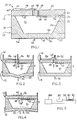
- Fig. 1 illustrates a pump apparatus 10 which includes a first substrate assembly 12 and a second substrate assembly 14.
- substrate assembly is meant to include a single substrate member and also a wafer formed from a single substrate member.
- the first substrate assembly 12 comprises a first substrate member 16 having a first exterior planar surface 18 on one side thereof and a second exterior planar surface 20 on an opposite side thereof.
- the first substrate member has a cavity 22 provided therein defined by a cavity side wall 24 and bottom wall 26.
- the cavity has an opening 23 located in the plane of surface 20.
- a portion of the first member located between the first exterior surface 18 and the bottom wall 26 of the cavity defines a diaphragm 28.
- a resistor 30 which terminates at terminal pads 32, 34 is embedded in the diaphragm 28 proximate surface 18.
- the second substrate assembly 14 comprises a second substrate member 40 having a first planar surface 42 on one side thereof and a second planar surface 44 on an opposite thereof which is parallel to surface 42.
- First and second holes 46, 48 extend through the second member.
- First and second flappers 52, 54 are associated with the first and second holes in second substrate member 40.
- the first flapper comprises a generally T-shaped configuration (see Fig. 15) having a branch portion 56 attached to the first surface 42 of substrate member 40 and having a trunk portion 58 positioned in spaced apart, overlying relationship with hole 46.
- the second flapper comprises a generally T-shaped configuration (see Fig. 14) having a branch portion 62 attached to the second surface 44 of substrate member 40 and having a trunk portion 64 positioned in spaced apart, overlying relationship with hole 48.
- the second surface 20 of the first substrate member 16 is attached to the first surface 42 of the second substrate member 40 providing a sealed enclosure 70 defined by cavity walls 24, 26 and second substrate member first surface 42.
- the enclosure 70 which is adapted to hold a volume of fluid 71 therein has only two openings which are provided by holes 46 and 48.
- the resistor terminal pads 32, 34 are connected to a power source 80, e.g. a 5 volt battery, which provides electrical energy to heat the resistor 30.
- the battery is connected to the resistor through an oscillator circuit 82, e.g. a CMOS chip, which oscillates the supply of electrical energy provided to the resistor at a predetermined frequency, e.g. one oscillation cycle per millisecond.
- a predetermined frequency e.g. one oscillation cycle per millisecond.
- the pump apparatus is connected at surface 44 thereof to a fluid supply line 84 and a fluid discharge line 86, as by conventional conduit attachment means well known in the art.
- the first hole 46 in substrate member 14 enables fluid communication between the fluid supply line 84 and enclosure 70.
- the second hole 48 enables fluid communication between the fluid discharge line 86 and enclosure 70.
- the heating of resistor 30 causes a corresponding heating of diaphragm 28 which causes it to expand and buckle outwardly 92, Fig. 2.
- diaphragm 28 As the diaphragm buckles outwardly it causes the volume of enclosure 70 to expand thus drawing fluid into the enclosure through hole 46.
- the pressure of fluid in discharge line 86 causes end portion 64 of flapper 54 to be urged into engagement with the second surface 48 of substrate member 14 causing hole 48 to be sealed and thus preventing flow of fluid therethrough.
- each oscillation cycle is associated with pump intake and the cooling portion of each oscillation cycle corresponds to pump discharge.
- Hole 46 and flapper 52 function as a one-way intake valve and hole 48 and flapper 54 function as a one-way discharge valve.
- the total volume of fluid pumped during a single oscillation cycle may be e.g. 1 nanoliter.
- the diaphragm at ambient temperature with no external stress applied thereto may have a generally flat profile or may have a profile which is slightly outwardly convex, i.e. bowing away from enclosure 70.
- the diaphragm in an ambient temperature unstressed state (solid lines) is inwardly convex, i.e. bows toward enclosure 70.
- heating of the diaphragm causes it to expand in the direction of enclosure 70, as shown in dashed lines, thus decreasing the volume thereof.
- Cooling of the diaphragm in this embodiment causes it to return to its original shape thus increasing the volume of the cavity.
- the heating portion of each energy oscillation cycle is associated with pump discharge and the cooling portion of each cycle is associated with pump intake.
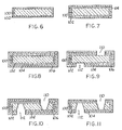
- a substrate member 100 corresponding to substrate member 14 in Fig. 1 is shown in cross section in Fig. 6.
- Substrate member 100 which may be a silicon substrate member which may be 400 microns thick, is provided with a first coating layer 102, which may be 0.1 microns thick, as by growing an oxide layer thereon, e.g. a silicon dioxide layer.
- an oxide layer thereon e.g. a silicon dioxide layer.
- the technique for growing of an oxide layer on a silicon substrate is well known in the art.
- Coating layer 104 may be 2 microns thick.
- the next step is to apply a third coating 106 over the second coating 104.
- the third coating may be a 0.2 micron thick LPCVD (low pressure chemical vapor deposition) silicon nitride layer which is applied by conventional LPCVD techniques well known in the art.
- LPCVD low pressure chemical vapor deposition
- Next holes 110, 112 extending through the three coating layers 102, 104, 106 are patterned and etched on opposite sides of the substrate assembly.
- the holes may be etched with carbon tetrafluoride (CF4), Fig. 9.
- Holes 110, 112 are then extended through the substrate member 100 as by etching with potassium hydroxide/isopropanol/water (KOH/ISO/H2O) as shown in Fig. 10.
- KOH/ISO/H2O potassium hydroxide/isopropanol/water
- the third layer 106 is stripped as by using phosphoric acid (H3PO4).
- the portion of the assembly which will become the flappers of the pump apparatus 10 is next patterned and etched as by using CF4.
- the etching material removes all of the first and second layers 102, 104 except for T-shaped masked portions thereof.
- the etching solution is allowed to remain in contact with the surface of substrate 100 and the perimeter surface of layer 102 thus causing etching of layer 102 to continue, as illustrated in Figs. 13-15.
- Figs. 14 and 15 are top and bottom plan views, respectively, of Fig. 13.
- This perimeter etching of layer 102 causes it to be removed from below the overlying third layer 104 so as to expose holes 110, 112.
- this perimeter etching of layer 102 has progressed to the point indicated in Figs. 13-15 it is terminated by removal of the etching solution thus providing a substrate assembly corresponding to substrate assembly 14 in Fig. 1.
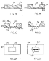
- a substrate member 200 corresponding to substrate member 12 of Fig. 1 is shown in cross section in Fig. 16.
- Substrate member 200 may be a 400 micron thick silicon substrate having a 385 micron thick heavily doped (e.g. 1018 atoms/cm3 phosphorous doped) upper portion 202 and a 15 micron thick lightly doped (e.g. 1016 atoms/cm3 phosphorous doped) lower region 204 which may be provided by a conventional epitaxy process well known in the art.
- a first coating layer 210 is applied to the substrate 200 which may be a 0.2 micron thick layer of LPCVD silicon nitride (Si3N 4) .
- a hole 212 is patterned and etched in the first layer 210 on the top side of the assembly as by using CF4 plasma.
- hole 212 is extended through the first portion 202 of the substrate 200 so as to provide a cavity 214 therein as by etching the exposed surface thereof with a 1:3:8 solution of hydrofluoric acid, nitric acid and acetic acid.
- a snaking pattern 216 corresponding in shape to electrical element 30, 32, 34 in Fig. 1, is then etched in the first layer 210 on the bottom side of the assembly as by using CF4, as illustrated in Fig. 20.
- resistors 218 e.g. phosphorus resistors are implanted in the lightly doped portion 204 of the substrate in the surface thereof exposed by the snaking pattern etched in layer 210.
- This resistor implant may be performed using the technique of ion implantation which is well known in the art.
- the resistor pattern provided may have a resistance of e.g. 1000 ohms.
- the remaining portion of coating layer 210 is stripped away as by using H3PO4.
- Figs. 22 and 23 are top and bottom plan views of Fig. 21 showing the cavity 214 and resistor 218 configurations provided in substrate 200.
- top surface of substrate 200 shown in Fig. 22 is then positioned in contact with the bottom surface of substrate 100 shown in Fig. 15 and the two substrates are bonded together as by silicon-silicon fusion bonding, which is well known in the art, so as to provide a pump assembly 10 such as shown in Fig. 1.
Description
- The invention relates to a pump apparatus according to the preamble of claim 1, to a method of pumping fluid through an enclosure means and to a method of making a pump apparatus. A pump apparatus according to the preamble of claim 1 is known from the US-A-4 895 500.
- The US-A-4 895 500 discloses a pump apparatus having an enclosure for holding a volume of fluid, an intake one-way valve for enabling intake of fluid into said enclosure, a discharge one-way valve for enabling discharge of fluid from said enclosure, a diaphragm for cyclically deflectable increasing and decreasing said volume of said enclosure to draw fluid into that enclosure and discharge fluid therefrom, and means for deflecting said diaphragm.
- There are many processes in which a relatively small quantity of fluid, either gas or liquid, must be dispensed in a measured amount. One typical process of this type is the process of liquid chromatography in which a precise amount of liquid in a quantity of e.g. 1 microliter must be dispensed to a separation column. In applications in which such small quantities of fluid are to be dispensed by pump, a difficulty in precise metering arises if the pump chamber is relatively large as compared to the quantity of fluid which is to be dispensed. The construction of pumps with extremely small pumping chambers has heretofore proven to be difficult and expensive.
- Certain microfabrication techniques for constructing valves are described in U.S. Patents 4,821,997 and 4,824,073 of Zdeblick and in U.S. patent application serial number 560,933, filed July 31, 1990, of Beatty and Beckmann for Control Valve Using Mechanical Beam Buckling, each of which is hereby specifically incorporated by reference for all that is disclosed therein.
- The present invention is directed to a method of constructing a pump apparatus which may readily employ microfabrication techniques and which may achieve the advantages associated with microfabrication such as batch fabrication, low cost, repeatability and the like. The invention is also directed to a pump apparatus which may have a very small dead volume and which may have a quick response and accurate dispensing characteristics. The pump apparatus may employ a diaphragm which is actuated by oscillatory heating and cooling thereof.
- Thus, the invention provides a pump apparatus having the features of claim 1. The invention further comprises a method of pumping fluid according to claim 9 and a method of making a pump apparatus according to
claim 12. - An illustrative and presently preferred embodiment of the invention is shown in the accompanying drawings in which:
- Fig. 1 is a cross sectional elevation view of a pump apparatus.
- Fig. 2 is a cross sectional elevation view of the pump apparatus of Fig. 1 with the diaphragm thereof moving outwardly during pump intake.
- Fig. 3 is a cross sectional elevation view of the pump apparatus of Fig. 1 with the diaphragm thereof moving inwardly during pump discharge.
- Fig. 4 is a cross sectional elevation view of an alternative embodiment of a pump assembly.
- Fig. 5 is a schematic diagram illustrating an assembly for oscillatingly heating a pump diaphragm.
- Figs. 6-13 are cross sectional elevation views illustrating various stages of wafer formation during the fabrication of one portion of the pump assembly shown in Fig. 1.
- Fig. 14 is a top plan view of the substrate assembly shown in Fig. 13.
- Fig. 15 is a bottom plan view of the substrate assembly shown in Fig. 13.
- Figs. 16-21 are cross sectional elevation views illustrating various stages of wafer formation during the fabrication of another portion of the pump assembly shown in Fig. 1.
- Fig. 22 is a top plan view of the substrate assembly shown in Fig. 21.
- Fig. 23 is a bottom plan view of the substrate assembly shown in Fig. 21.
- Fig. 1 illustrates a pump apparatus 10 which includes a
first substrate assembly 12 and asecond substrate assembly 14. As used herein, "substrate assembly" is meant to include a single substrate member and also a wafer formed from a single substrate member. Thefirst substrate assembly 12 comprises afirst substrate member 16 having a first exteriorplanar surface 18 on one side thereof and a second exteriorplanar surface 20 on an opposite side thereof. The first substrate member has acavity 22 provided therein defined by acavity side wall 24 andbottom wall 26. The cavity has anopening 23 located in the plane ofsurface 20. A portion of the first member located between the firstexterior surface 18 and thebottom wall 26 of the cavity defines adiaphragm 28. Aresistor 30 which terminates atterminal pads diaphragm 28proximate surface 18. - The
second substrate assembly 14 comprises asecond substrate member 40 having a firstplanar surface 42 on one side thereof and a secondplanar surface 44 on an opposite thereof which is parallel tosurface 42. First andsecond holes - First and
second flappers second substrate member 40. The first flapper comprises a generally T-shaped configuration (see Fig. 15) having abranch portion 56 attached to thefirst surface 42 ofsubstrate member 40 and having atrunk portion 58 positioned in spaced apart, overlying relationship withhole 46. The second flapper comprises a generally T-shaped configuration (see Fig. 14) having abranch portion 62 attached to thesecond surface 44 ofsubstrate member 40 and having atrunk portion 64 positioned in spaced apart, overlying relationship withhole 48. - As shown in Fig. 1, the
second surface 20 of thefirst substrate member 16 is attached to thefirst surface 42 of thesecond substrate member 40 providing a sealedenclosure 70 defined bycavity walls first surface 42. Theenclosure 70 which is adapted to hold a volume offluid 71 therein has only two openings which are provided byholes - As shown schematically in Fig. 5, the
resistor terminal pads power source 80, e.g. a 5 volt battery, which provides electrical energy to heat theresistor 30. The battery is connected to the resistor through anoscillator circuit 82, e.g. a CMOS chip, which oscillates the supply of electrical energy provided to the resistor at a predetermined frequency, e.g. one oscillation cycle per millisecond. During each oscillation cycle the resistor heats during a period when energy is supplied thereto and then cools during a period when energy is not supplied thereto. - In use the pump apparatus is connected at
surface 44 thereof to afluid supply line 84 and afluid discharge line 86, as by conventional conduit attachment means well known in the art. Thefirst hole 46 insubstrate member 14 enables fluid communication between thefluid supply line 84 andenclosure 70. Thesecond hole 48 enables fluid communication between thefluid discharge line 86 andenclosure 70. - In one embodiment of the invention, which is presently the best mode contemplated, the heating of
resistor 30 causes a corresponding heating ofdiaphragm 28 which causes it to expand and buckle outwardly 92, Fig. 2. As the diaphragm buckles outwardly it causes the volume ofenclosure 70 to expand thus drawing fluid into the enclosure throughhole 46. As the outward buckling takes place the pressure of fluid indischarge line 86 causesend portion 64 offlapper 54 to be urged into engagement with thesecond surface 48 ofsubstrate member 14 causinghole 48 to be sealed and thus preventing flow of fluid therethrough. - During a period when
resistor 30 anddiaphragm 28 are cooling the diaphragm contracts and buckles inwardly 94, Fig. 3, causing a reduction of volume inenclosure 70 with a corresponding pressure increase which causesend portion 58 offlapper 52 to be urged into engagement withsurface 28sealing hole 46. This pressure increase inenclosure 70 also urges flapper 54 away fromsurface 44 thus openinghole 48 and enabling discharge of fluid fromenclosure 70. - Thus in the embodiment of Figs. 1-3 the resistor heating portion of each oscillation cycle is associated with pump intake and the cooling portion of each oscillation cycle corresponds to pump discharge.
Hole 46 and flapper 52 function as a one-way intake valve andhole 48 and flapper 54 function as a one-way discharge valve. The total volume of fluid pumped during a single oscillation cycle may be e.g. 1 nanoliter. - In the embodiment of Figs. 1-3 the diaphragm at ambient temperature with no external stress applied thereto may have a generally flat profile or may have a profile which is slightly outwardly convex, i.e. bowing away from
enclosure 70. - In another embodiment of the invention, as illustrated in Fig.4, the diaphragm in an ambient temperature unstressed state (solid lines) is inwardly convex, i.e. bows toward
enclosure 70. In this embodiment heating of the diaphragm causes it to expand in the direction ofenclosure 70, as shown in dashed lines, thus decreasing the volume thereof. Cooling of the diaphragm in this embodiment causes it to return to its original shape thus increasing the volume of the cavity. Thus in the embodiment of Fig. 4 the heating portion of each energy oscillation cycle is associated with pump discharge and the cooling portion of each cycle is associated with pump intake. - Other means of heating the diaphragm to provide oscillatory movement thereof might also be employed such as application of light energy or microwave energy or inductive heat thereto.
- A specific method of fabricating a pump apparatus 10 will now be described with reference to Figs. 6-23.
- A
substrate member 100 corresponding tosubstrate member 14 in Fig. 1 is shown in cross section in Fig. 6.Substrate member 100, which may be a silicon substrate member which may be 400 microns thick, is provided with afirst coating layer 102, which may be 0.1 microns thick, as by growing an oxide layer thereon, e.g. a silicon dioxide layer. The technique for growing of an oxide layer on a silicon substrate is well known in the art. - Next a
second coating layer 104, e.g. a polysilicon coating is deposited over the first coating by a chemical vapor deposit technique well known in the art, Fig. 7.Coating layer 104 may be 2 microns thick. - The next step, as illustrated by Fig. 8, is to apply a
third coating 106 over thesecond coating 104. The third coating may be a 0.2 micron thick LPCVD (low pressure chemical vapor deposition) silicon nitride layer which is applied by conventional LPCVD techniques well known in the art. -
Next holes coating layers -
Holes substrate member 100 as by etching with potassium hydroxide/isopropanol/water (KOH/ISO/H₂O) as shown in Fig. 10. - Next, as shown in Fig. 11, the
third layer 106 is stripped as by using phosphoric acid (H₃PO₄). - The portion of the assembly which will become the flappers of the pump apparatus 10 is next patterned and etched as by using CF₄. Initially, as shown by Fig. 12, the etching material removes all of the first and
second layers substrate 100 and the perimeter surface oflayer 102 thus causing etching oflayer 102 to continue, as illustrated in Figs. 13-15. (Figs. 14 and 15 are top and bottom plan views, respectively, of Fig. 13.) This perimeter etching oflayer 102 causes it to be removed from below the overlyingthird layer 104 so as to exposeholes layer 102 has progressed to the point indicated in Figs. 13-15 it is terminated by removal of the etching solution thus providing a substrate assembly corresponding tosubstrate assembly 14 in Fig. 1. - A
substrate member 200 corresponding tosubstrate member 12 of Fig. 1 is shown in cross section in Fig. 16.Substrate member 200 may be a 400 micron thick silicon substrate having a 385 micron thick heavily doped (e.g. 10¹⁸ atoms/cm³ phosphorous doped)upper portion 202 and a 15 micron thick lightly doped (e.g. 10¹⁶ atoms/cm³ phosphorous doped)lower region 204 which may be provided by a conventional epitaxy process well known in the art. - As illustrated in Fig. 17 a
first coating layer 210 is applied to thesubstrate 200 which may be a 0.2 micron thick layer of LPCVD silicon nitride (Si₃N4). - As illustrated by Fig. 18, a
hole 212 is patterned and etched in thefirst layer 210 on the top side of the assembly as by using CF₄ plasma. - Next, as illustrated in Fig. 19,
hole 212 is extended through thefirst portion 202 of thesubstrate 200 so as to provide acavity 214 therein as by etching the exposed surface thereof with a 1:3:8 solution of hydrofluoric acid, nitric acid and acetic acid. - A
snaking pattern 216, corresponding in shape toelectrical element first layer 210 on the bottom side of the assembly as by using CF₄, as illustrated in Fig. 20. - Next, as illustrated in dashed lines in Fig. 20,
resistors 218 e.g. phosphorus resistors are implanted in the lightly dopedportion 204 of the substrate in the surface thereof exposed by the snaking pattern etched inlayer 210. This resistor implant may be performed using the technique of ion implantation which is well known in the art. The resistor pattern provided may have a resistance of e.g. 1000 ohms. - Next, as illustrated by Fig. 21, the remaining portion of
coating layer 210 is stripped away as by using H₃PO₄. - Figs. 22 and 23 are top and bottom plan views of Fig. 21 showing the
cavity 214 andresistor 218 configurations provided insubstrate 200. - The top surface of
substrate 200 shown in Fig. 22 is then positioned in contact with the bottom surface ofsubstrate 100 shown in Fig. 15 and the two substrates are bonded together as by silicon-silicon fusion bonding, which is well known in the art, so as to provide a pump assembly 10 such as shown in Fig. 1.
Claims (15)
- A pump apparatus comprising:
enclosure means (70) for holding a volume of fluid;
intake one-way valve means (46, 58) operatively associated with said enclosure means for enabling intake of fluid into said enclosure means (70);
discharge one-way valve means (48, 64) operatively associated with said enclosure means (70) for enabling discharge of fluid from said enclosure means;
diaphragm means (28) operatively associated with said enclosure means (70) for cyclically deflectably increasing and decreasing said volume of said enclosure means (70) whereby fluid is cyclically drawn into said enclosure means and discharged therefrom; and
means (30) operatively associated with said diaphragm means (28) for selectively cyclically deflecting said diaphragm means;
characterized in that
said diaphragm means is formed by microfabrication techniques from a wafer comprising a single substrate layer (200) and at least one coating layer (210);
said means (30) for deflecting the diaphragm means is a heating means (30) for selectively cyclically applying heat to said diaphragm means and terminating application of heat thereto; and
said heating means comprises resistor means (218) integrally formed with said diaphragm means by microfabrication techniques for heating said diaphragm means in response to an electrical current passed therethrough. - The apparatus of claim 1 wherein said diaphragm means (28) consists of a portion of said substrate layer of said wafer.
- The apparatus of claims 1 wherein said enclosure means comprises a pump body formed from a first substrate assembly (12) having a first surface (18) defining an exterior portion of said diaphragm means (28) and a second surface (20) defining an opening (23) of a pump body cavity (22).
- The apparatus of claim 3 wherein said diaphragm means (28) interfaces with said pump body cavity (22) at an internal surface portion (26) of said first substrate assembly (12).
- The apparatus of claim 4 further comprising a second substrate assembly (14) attached to said second surface (20) of said first substrate assembly (12) in overlying relationship with said cavity opening (23).
- The apparatus of claim 5 wherein at least a portion of at least one of said intake and discharge one-way valve means (46,58 and 48,64) are formed from said second substrate member (14).
- The apparatus of claim 5 wherein said second substrate assembly (14) comprises a first surface (42) attached to said second surface (20) of said first substrate assembly (12) and a second surface (44) positioned parallel to said first surface (42) of said second substrate assembly (14); and wherein said intake one-way valve means comprises:
a first hole (46) extending between said first and second surfaces (42,44) of said second substrate member (14); and
a first flapper (52) having a first end (56) attached to said first surface (42) of said second substrate assembly (14) and a second end (58) positioned over said first hole (46) in said second substrate assembly (14) in displaceable relationship therewith. - The apparatus of claim 7 wherein said discharge one-way valve means comprises:
a second hole (48) extending between said first and second surfaces (42,44) of said second substrate assembly (14); and
a second flapper (54) having a first end (62) attached to said second surface (44) of said second substrate assembly (14) and a second end (64) positioned over said second hole (48) in said second substrate assembly (14) in displaceable relationship therewith. - A method of pumping fluid through an enclosure means (70) having an intake one-way valve (46) and an outlet one-way valve (64) the method comprising:a) providing a substrate layer (200) which is adapted to form a first layer of an integral wafer;b) applying at least one coating layer (210) to said first substrate member to provide at least a second layer of said integral wafer;c) employing microfabrication techniques to expose opposite surface portions of a single one of said at least two layers of said integral wafer so as to create a pump diaphragm having an integrally formed resistor pattern therein from said single one of said layers in the portion thereof having said opposite exposed surface portions, the diaphragm being operatively associated with said enclosure means (70);d) cyclically heating said pump diaphragm formed from said single layer of said wafer by microfabrication techniques by passing electrical current through said internally formed resistor pattern so as to expand and contract said pump diaphragm to pump fluid through the associated enclosure means (70).
- The method of claim 9 wherein deflecting the diaphragm (28) in the first direction (92) comprises heating the diaphragm and deflecting the diaphragm in the second direction (94) comprises terminating the heating of the diaphragm.
- The method of claim 9 wherein deflecting the diaphragm in the second direction (94) comprises heating the diaphragm (28) and deflecting the diaphragm in the first direction (92) comprises terminating the heating of the diaphragm.
- A method of making a pump apparatus according to one of claims 1 to 7 comprising the steps of forming a cavity (22) with an interfacing diaphragm (28) in a first substrate assembly (12);
forming a pair of one-way valves (46, 58; 48, 64) in a second substrate assembly (14);
attaching said first substrate assembly (12) to said second substrate assembly (14);
attaching a cyclic heat source (34) to the diaphragm (28), wherein the step of forming a pair of one-way valves (46, 58; 48, 64) comprises the steps of:
forming a first hole through the second substrate assembly;
forming a first flapper having a deflectable free end disposed in alignment with the hole which is flexibly displaceable into sealing relationship with the hole. - The method of claim 12, wherein said diaphragm (28) is made of one material, not bimetallic.
- The method of claim 12 or 13, wherein said valves comprise orifices (46,48) and flappers (56;64) said orifices and flappers being made from the same substrate (40).
- The method of claim 12 wherein said diaphragm (28; 200) is implanted with a pattern of electrically conductive resistor material (218) through the use of microfabrication techniques.
Applications Claiming Priority (2)
| Application Number | Priority Date | Filing Date | Title |
|---|---|---|---|
| US60588390A | 1990-10-30 | 1990-10-30 | |
| US605883 | 1990-10-30 |
Publications (2)
| Publication Number | Publication Date |
|---|---|
| EP0483469A1 EP0483469A1 (en) | 1992-05-06 |
| EP0483469B1 true EP0483469B1 (en) | 1994-10-12 |
Family
ID=24425592
Family Applications (1)
| Application Number | Title | Priority Date | Filing Date |
|---|---|---|---|
| EP91113680A Expired - Lifetime EP0483469B1 (en) | 1990-10-30 | 1991-08-14 | Micropump |
Country Status (4)
| Country | Link |
|---|---|
| US (1) | US5129794A (en) |
| EP (1) | EP0483469B1 (en) |
| JP (1) | JP3144698B2 (en) |
| DE (1) | DE69104585T2 (en) |
Cited By (1)
| Publication number | Priority date | Publication date | Assignee | Title |
|---|---|---|---|---|
| DE19507978A1 (en) * | 1995-03-07 | 1996-09-12 | Heinzl Joachim | Burner arrangement for liquid fuels |
Families Citing this family (111)
| Publication number | Priority date | Publication date | Assignee | Title |
|---|---|---|---|---|
| US5368582A (en) * | 1992-08-10 | 1994-11-29 | The Schepens Eye Research Institute | Method and apparatus for introducing fluid material into an eye |
| US5458834A (en) * | 1993-10-07 | 1995-10-17 | Corning Incorporated | Extrusion of low viscosity batch |
| US5476367A (en) * | 1994-07-07 | 1995-12-19 | Shurflo Pump Manufacturing Co. | Booster pump with sealing gasket including inlet and outlet check valves |
| US6164742A (en) * | 1994-09-14 | 2000-12-26 | Hewlett-Packard Company | Active accumulator system for an ink-jet pen |
| US5838351A (en) * | 1995-10-26 | 1998-11-17 | Hewlett-Packard Company | Valve assembly for controlling fluid flow within an ink-jet pen |
| US5632607A (en) * | 1995-11-01 | 1997-05-27 | Shurflo Pump Manufacturing Co. | Piston and valve arrangement for a wobble plate type pump |
| US5791882A (en) * | 1996-04-25 | 1998-08-11 | Shurflo Pump Manufacturing Co | High efficiency diaphragm pump |
| US5880752A (en) * | 1996-05-09 | 1999-03-09 | Hewlett-Packard Company | Print system for ink-jet pens |
| US6130694A (en) * | 1996-05-13 | 2000-10-10 | Hewlett-Packard Company | Regulator assembly for modulating fluid pressure within an ink-jet printer |
| US5872582A (en) * | 1996-07-02 | 1999-02-16 | Hewlett-Packard Company | Microfluid valve for modulating fluid flow within an ink-jet printer |
| US6116863A (en) * | 1997-05-30 | 2000-09-12 | University Of Cincinnati | Electromagnetically driven microactuated device and method of making the same |
| US6048183A (en) * | 1998-02-06 | 2000-04-11 | Shurflo Pump Manufacturing Co. | Diaphragm pump with modified valves |
| US7070577B1 (en) | 1998-02-02 | 2006-07-04 | Medtronic, Inc | Drive circuit having improved energy efficiency for implantable beneficial agent infusion or delivery device |
| WO1999038551A1 (en) | 1998-02-02 | 1999-08-05 | Medtronic, Inc. | Implantable drug infusion device having a safety valve |
| JP3543604B2 (en) | 1998-03-04 | 2004-07-14 | 株式会社日立製作所 | Liquid sending device and automatic analyzer |
| US6360036B1 (en) * | 2000-01-14 | 2002-03-19 | Corning Incorporated | MEMS optical switch and method of manufacture |
| ATE307976T1 (en) | 2000-05-25 | 2005-11-15 | Debiotech Sa | MICRO-MACHINED FLUIDIC DEVICE AND MANUFACTURING METHOD |
| US7016022B2 (en) * | 2000-08-02 | 2006-03-21 | Honeywell International Inc. | Dual use detectors for flow cytometry |
| US7215425B2 (en) * | 2000-08-02 | 2007-05-08 | Honeywell International Inc. | Optical alignment for flow cytometry |
| US7641856B2 (en) * | 2004-05-14 | 2010-01-05 | Honeywell International Inc. | Portable sample analyzer with removable cartridge |
| US7130046B2 (en) * | 2004-09-27 | 2006-10-31 | Honeywell International Inc. | Data frame selection for cytometer analysis |
| US7630063B2 (en) * | 2000-08-02 | 2009-12-08 | Honeywell International Inc. | Miniaturized cytometer for detecting multiple species in a sample |
| US7283223B2 (en) * | 2002-08-21 | 2007-10-16 | Honeywell International Inc. | Cytometer having telecentric optics |
| US7553453B2 (en) * | 2000-06-02 | 2009-06-30 | Honeywell International Inc. | Assay implementation in a microfluidic format |
| US7420659B1 (en) | 2000-06-02 | 2008-09-02 | Honeywell Interantional Inc. | Flow control system of a cartridge |
| US7471394B2 (en) * | 2000-08-02 | 2008-12-30 | Honeywell International Inc. | Optical detection system with polarizing beamsplitter |
| US8329118B2 (en) * | 2004-09-02 | 2012-12-11 | Honeywell International Inc. | Method and apparatus for determining one or more operating parameters for a microfluidic circuit |
| US6970245B2 (en) * | 2000-08-02 | 2005-11-29 | Honeywell International Inc. | Optical alignment detection system |
| US7242474B2 (en) * | 2004-07-27 | 2007-07-10 | Cox James A | Cytometer having fluid core stream position control |
| US7262838B2 (en) * | 2001-06-29 | 2007-08-28 | Honeywell International Inc. | Optical detection system for flow cytometry |
| US6568286B1 (en) | 2000-06-02 | 2003-05-27 | Honeywell International Inc. | 3D array of integrated cells for the sampling and detection of air bound chemical and biological species |
| US7978329B2 (en) * | 2000-08-02 | 2011-07-12 | Honeywell International Inc. | Portable scattering and fluorescence cytometer |
| US20060263888A1 (en) * | 2000-06-02 | 2006-11-23 | Honeywell International Inc. | Differential white blood count on a disposable card |
| US8071051B2 (en) | 2004-05-14 | 2011-12-06 | Honeywell International Inc. | Portable sample analyzer cartridge |
| US6837476B2 (en) * | 2002-06-19 | 2005-01-04 | Honeywell International Inc. | Electrostatically actuated valve |
| US7000330B2 (en) * | 2002-08-21 | 2006-02-21 | Honeywell International Inc. | Method and apparatus for receiving a removable media member |
| US7277166B2 (en) * | 2000-08-02 | 2007-10-02 | Honeywell International Inc. | Cytometer analysis cartridge optical configuration |
| US7061595B2 (en) * | 2000-08-02 | 2006-06-13 | Honeywell International Inc. | Miniaturized flow controller with closed loop regulation |
| US6382228B1 (en) | 2000-08-02 | 2002-05-07 | Honeywell International Inc. | Fluid driving system for flow cytometry |
| US7280014B2 (en) | 2001-03-13 | 2007-10-09 | Rochester Institute Of Technology | Micro-electro-mechanical switch and a method of using and making thereof |
| AU2002303933A1 (en) | 2001-05-31 | 2002-12-09 | Rochester Institute Of Technology | Fluidic valves, agitators, and pumps and methods thereof |
| GB0123054D0 (en) * | 2001-09-25 | 2001-11-14 | Randox Lab Ltd | Passive microvalve |
| US6729856B2 (en) | 2001-10-09 | 2004-05-04 | Honeywell International Inc. | Electrostatically actuated pump with elastic restoring forces |
| US7378775B2 (en) | 2001-10-26 | 2008-05-27 | Nth Tech Corporation | Motion based, electrostatic power source and methods thereof |
| US7211923B2 (en) | 2001-10-26 | 2007-05-01 | Nth Tech Corporation | Rotational motion based, electrostatic power source and methods thereof |
| US6715994B2 (en) * | 2001-11-12 | 2004-04-06 | Shurflo Pump Manufacturing Co., Inc. | Bilge pump |
| US6623245B2 (en) | 2001-11-26 | 2003-09-23 | Shurflo Pump Manufacturing Company, Inc. | Pump and pump control circuit apparatus and method |
| US7083392B2 (en) * | 2001-11-26 | 2006-08-01 | Shurflo Pump Manufacturing Company, Inc. | Pump and pump control circuit apparatus and method |
| KR100493208B1 (en) * | 2002-06-12 | 2005-06-03 | 양상식 | A micropump for the control of ultramicro flow and the manufacturing method |
| DE10242110A1 (en) * | 2002-09-11 | 2004-03-25 | Thinxxs Gmbh | Micro-pump for chemical and biochemical analysis has valves arranged in recesses in the base part and formed by a valve seat and a valve body |
| US7287328B2 (en) | 2003-08-29 | 2007-10-30 | Rochester Institute Of Technology | Methods for distributed electrode injection |
| US7217582B2 (en) | 2003-08-29 | 2007-05-15 | Rochester Institute Of Technology | Method for non-damaging charge injection and a system thereof |
| JP2007519249A (en) * | 2004-01-22 | 2007-07-12 | コーニンクレッカ フィリップス エレクトロニクス エヌ ヴィ | Method and system for cooling at least one electronic device |
| US8581308B2 (en) | 2004-02-19 | 2013-11-12 | Rochester Institute Of Technology | High temperature embedded charge devices and methods thereof |
| US7612871B2 (en) * | 2004-09-01 | 2009-11-03 | Honeywell International Inc | Frequency-multiplexed detection of multiple wavelength light for flow cytometry |
| US7630075B2 (en) * | 2004-09-27 | 2009-12-08 | Honeywell International Inc. | Circular polarization illumination based analyzer system |
| US20060134510A1 (en) * | 2004-12-21 | 2006-06-22 | Cleopatra Cabuz | Air cell air flow control system and method |
| US7222639B2 (en) * | 2004-12-29 | 2007-05-29 | Honeywell International Inc. | Electrostatically actuated gas valve |
| US7328882B2 (en) * | 2005-01-06 | 2008-02-12 | Honeywell International Inc. | Microfluidic modulating valve |
| US7445017B2 (en) * | 2005-01-28 | 2008-11-04 | Honeywell International Inc. | Mesovalve modulator |
| US7688427B2 (en) | 2005-04-29 | 2010-03-30 | Honeywell International Inc. | Particle parameter determination system |
| US7320338B2 (en) * | 2005-06-03 | 2008-01-22 | Honeywell International Inc. | Microvalve package assembly |
| WO2007005907A1 (en) * | 2005-07-01 | 2007-01-11 | Honeywell International, Inc. | A molded cartridge with 3-d hydrodynamic focusing |
| JP2009500612A (en) * | 2005-07-01 | 2009-01-08 | ハネウェル・インターナショナル・インコーポレーテッド | Flow measurement analyzer |
| US8361410B2 (en) * | 2005-07-01 | 2013-01-29 | Honeywell International Inc. | Flow metered analyzer |
| US7517201B2 (en) * | 2005-07-14 | 2009-04-14 | Honeywell International Inc. | Asymmetric dual diaphragm pump |
| US7843563B2 (en) * | 2005-08-16 | 2010-11-30 | Honeywell International Inc. | Light scattering and imaging optical system |
| US20070051415A1 (en) * | 2005-09-07 | 2007-03-08 | Honeywell International Inc. | Microvalve switching array |
| US7624755B2 (en) * | 2005-12-09 | 2009-12-01 | Honeywell International Inc. | Gas valve with overtravel |
| JP2009521684A (en) * | 2005-12-22 | 2009-06-04 | ハネウェル・インターナショナル・インコーポレーテッド | Portable sample analyzer cartridge |
| JP5175213B2 (en) * | 2005-12-22 | 2013-04-03 | ハネウェル・インターナショナル・インコーポレーテッド | Portable sample analysis system |
| WO2007075920A2 (en) * | 2005-12-22 | 2007-07-05 | Honeywell International Inc. | Hematological analyzer system with removable cartridge |
| US7523762B2 (en) | 2006-03-22 | 2009-04-28 | Honeywell International Inc. | Modulating gas valves and systems |
| US8007704B2 (en) * | 2006-07-20 | 2011-08-30 | Honeywell International Inc. | Insert molded actuator components |
| US7543604B2 (en) * | 2006-09-11 | 2009-06-09 | Honeywell International Inc. | Control valve |
| US20080099082A1 (en) * | 2006-10-27 | 2008-05-01 | Honeywell International Inc. | Gas valve shutoff seal |
| EP1916420B1 (en) * | 2006-10-28 | 2009-09-23 | Sensirion Holding AG | Multicellular pump |
| US7644731B2 (en) * | 2006-11-30 | 2010-01-12 | Honeywell International Inc. | Gas valve with resilient seat |
| DE102007045637A1 (en) * | 2007-09-25 | 2009-04-02 | Robert Bosch Gmbh | Microdosing device for dosing small amounts of a medium |
| US20100034704A1 (en) * | 2008-08-06 | 2010-02-11 | Honeywell International Inc. | Microfluidic cartridge channel with reduced bubble formation |
| US8037354B2 (en) | 2008-09-18 | 2011-10-11 | Honeywell International Inc. | Apparatus and method for operating a computing platform without a battery pack |
| EP2511529A1 (en) * | 2011-04-15 | 2012-10-17 | Ikerlan, S. Coop. | Impulsion core for a fluid micropump |
| US8905063B2 (en) | 2011-12-15 | 2014-12-09 | Honeywell International Inc. | Gas valve with fuel rate monitor |
| US9557059B2 (en) | 2011-12-15 | 2017-01-31 | Honeywell International Inc | Gas valve with communication link |
| US9846440B2 (en) | 2011-12-15 | 2017-12-19 | Honeywell International Inc. | Valve controller configured to estimate fuel comsumption |
| US9835265B2 (en) | 2011-12-15 | 2017-12-05 | Honeywell International Inc. | Valve with actuator diagnostics |
| US9851103B2 (en) | 2011-12-15 | 2017-12-26 | Honeywell International Inc. | Gas valve with overpressure diagnostics |
| US8947242B2 (en) | 2011-12-15 | 2015-02-03 | Honeywell International Inc. | Gas valve with valve leakage test |
| US8839815B2 (en) | 2011-12-15 | 2014-09-23 | Honeywell International Inc. | Gas valve with electronic cycle counter |
| US9074770B2 (en) | 2011-12-15 | 2015-07-07 | Honeywell International Inc. | Gas valve with electronic valve proving system |
| US9995486B2 (en) | 2011-12-15 | 2018-06-12 | Honeywell International Inc. | Gas valve with high/low gas pressure detection |
| US8899264B2 (en) | 2011-12-15 | 2014-12-02 | Honeywell International Inc. | Gas valve with electronic proof of closure system |
| US8741233B2 (en) | 2011-12-27 | 2014-06-03 | Honeywell International Inc. | Disposable cartridge for fluid analysis |
| US8741234B2 (en) | 2011-12-27 | 2014-06-03 | Honeywell International Inc. | Disposable cartridge for fluid analysis |
| US8741235B2 (en) | 2011-12-27 | 2014-06-03 | Honeywell International Inc. | Two step sample loading of a fluid analysis cartridge |
| US8663583B2 (en) | 2011-12-27 | 2014-03-04 | Honeywell International Inc. | Disposable cartridge for fluid analysis |
| US10422531B2 (en) | 2012-09-15 | 2019-09-24 | Honeywell International Inc. | System and approach for controlling a combustion chamber |
| US9234661B2 (en) | 2012-09-15 | 2016-01-12 | Honeywell International Inc. | Burner control system |
| DE102013101573A1 (en) | 2013-02-18 | 2014-08-21 | Emitec France S.A.S | Method for heating a conveyor |
| EP2868970B1 (en) | 2013-10-29 | 2020-04-22 | Honeywell Technologies Sarl | Regulating device |
| MX2016006752A (en) | 2013-11-29 | 2016-09-07 | Koninklijke Philips Nv | Valve and manufacturing method for manufacturing the valve. |
| US10024439B2 (en) | 2013-12-16 | 2018-07-17 | Honeywell International Inc. | Valve over-travel mechanism |
| US9841122B2 (en) | 2014-09-09 | 2017-12-12 | Honeywell International Inc. | Gas valve with electronic valve proving system |
| US9645584B2 (en) | 2014-09-17 | 2017-05-09 | Honeywell International Inc. | Gas valve with electronic health monitoring |
| US10100822B2 (en) | 2015-04-20 | 2018-10-16 | Hewlett-Packard Development Company, L.P. | Pump having freely movable member |
| US10352314B2 (en) | 2015-04-20 | 2019-07-16 | Hewlett-Packard Development Company, L.P. | Pump having freely movable member |
| WO2016171658A1 (en) | 2015-04-20 | 2016-10-27 | Hewlett-Packard Development Company, L.P. | Electronic device having a coolant |
| US10503181B2 (en) | 2016-01-13 | 2019-12-10 | Honeywell International Inc. | Pressure regulator |
| US10564062B2 (en) | 2016-10-19 | 2020-02-18 | Honeywell International Inc. | Human-machine interface for gas valve |
| US11073281B2 (en) | 2017-12-29 | 2021-07-27 | Honeywell International Inc. | Closed-loop programming and control of a combustion appliance |
| US10697815B2 (en) | 2018-06-09 | 2020-06-30 | Honeywell International Inc. | System and methods for mitigating condensation in a sensor module |
Family Cites Families (9)
| Publication number | Priority date | Publication date | Assignee | Title |
|---|---|---|---|---|
| US3606592A (en) * | 1970-05-20 | 1971-09-20 | Bendix Corp | Fluid pump |
| US4411603A (en) * | 1981-06-24 | 1983-10-25 | Cordis Dow Corp. | Diaphragm type blood pump for medical use |
| US4636149A (en) * | 1985-05-13 | 1987-01-13 | Cordis Corporation | Differential thermal expansion driven pump |
| US4824073A (en) * | 1986-09-24 | 1989-04-25 | Stanford University | Integrated, microminiature electric to fluidic valve |
| US4821997A (en) * | 1986-09-24 | 1989-04-18 | The Board Of Trustees Of The Leland Stanford Junior University | Integrated, microminiature electric-to-fluidic valve and pressure/flow regulator |
| US4911616A (en) * | 1988-01-19 | 1990-03-27 | Laumann Jr Carl W | Micro miniature implantable pump |
| US4938742A (en) * | 1988-02-04 | 1990-07-03 | Smits Johannes G | Piezoelectric micropump with microvalves |
| SE8801299L (en) * | 1988-04-08 | 1989-10-09 | Bertil Hoeoek | MICROMECHANICAL ONE-WAY VALVE |
| DE3814150A1 (en) * | 1988-04-27 | 1989-11-09 | Draegerwerk Ag | VALVE ARRANGEMENT MADE FROM MICROSTRUCTURED COMPONENTS |
-
1991
- 1991-08-14 DE DE69104585T patent/DE69104585T2/en not_active Expired - Fee Related
- 1991-08-14 EP EP91113680A patent/EP0483469B1/en not_active Expired - Lifetime
- 1991-08-26 US US07/754,172 patent/US5129794A/en not_active Expired - Lifetime
- 1991-10-30 JP JP31165791A patent/JP3144698B2/en not_active Expired - Fee Related
Cited By (2)
| Publication number | Priority date | Publication date | Assignee | Title |
|---|---|---|---|---|
| DE19507978A1 (en) * | 1995-03-07 | 1996-09-12 | Heinzl Joachim | Burner arrangement for liquid fuels |
| DE19507978C2 (en) * | 1995-03-07 | 2002-03-07 | Joachim Heinzl | Burner arrangement for liquid fuels |
Also Published As
| Publication number | Publication date |
|---|---|
| DE69104585T2 (en) | 1995-05-18 |
| JPH06341376A (en) | 1994-12-13 |
| EP0483469A1 (en) | 1992-05-06 |
| US5129794A (en) | 1992-07-14 |
| JP3144698B2 (en) | 2001-03-12 |
| DE69104585D1 (en) | 1994-11-17 |
Similar Documents
| Publication | Publication Date | Title |
|---|---|---|
| EP0483469B1 (en) | Micropump | |
| EP0469749B1 (en) | Control valve utilizing mechanical beam buckling | |
| US5417235A (en) | Integrated microvalve structures with monolithic microflow controller | |
| US5085562A (en) | Micropump having a constant output | |
| US4911616A (en) | Micro miniature implantable pump | |
| US5870518A (en) | Microactuator for precisely aligning an optical fiber and an associated fabrication method | |
| US4826131A (en) | Electrically controllable valve etched from silicon substrates | |
| US5336062A (en) | Microminiaturized pump | |
| EP0261972B1 (en) | Integrated, microminiature electric-to-fluidic valve and pressure/flow regulator and method of making same | |
| JP4539898B2 (en) | Micromechanic pump | |
| KR20010041955A (en) | Apparatus and method for fabricating needles via conformal deposition in two-piece molds | |
| US20020081866A1 (en) | Thermally driven micro-pump buried in a silicon substrate and method for fabricating the same | |
| US6874871B2 (en) | Integratedly molded ink jet printer head manufacturing method | |
| EP1296067B1 (en) | Passive microvalve | |
| JPH051669A (en) | Manufacture of micro-pump and micro-valve | |
| US6716661B2 (en) | Process to fabricate an integrated micro-fluidic system on a single wafer | |
| US20190358955A1 (en) | Fluid ejection microfluidic device, in particular for ink printing, and manufacturing process thereof | |
| TW202012302A (en) | Methods of fabricating micro-valves and jetting assemblies including such micro-valves | |
| US7740459B2 (en) | Micropump having a pump diaphragm and a polysilicon layer | |
| EP0435653B1 (en) | Micropump | |
| EP1974922B1 (en) | Highly Integrated Wafer Bonded MEMS Devices with Release-Free Membrane Manufacture for High Density Print Heads | |
| EP1235687B1 (en) | Resonant cavity droplet ejector with localized ultrasonic excitation and method of making same | |
| US6533951B1 (en) | Method of manufacturing fluid pump | |
| CN209940465U (en) | Microfluidic actuator | |
| JP3109703B2 (en) | Membrane structure, method of manufacturing the same, and microdevice using the same |
Legal Events
| Date | Code | Title | Description |
|---|---|---|---|
| PUAI | Public reference made under article 153(3) epc to a published international application that has entered the european phase |
Free format text: ORIGINAL CODE: 0009012 |
|
| AK | Designated contracting states |
Kind code of ref document: A1 Designated state(s): DE FR GB |
|
| 17P | Request for examination filed |
Effective date: 19920511 |
|
| 17Q | First examination report despatched |
Effective date: 19920904 |
|
| GRAA | (expected) grant |
Free format text: ORIGINAL CODE: 0009210 |
|
| AK | Designated contracting states |
Kind code of ref document: B1 Designated state(s): DE FR GB |
|
| PG25 | Lapsed in a contracting state [announced via postgrant information from national office to epo] |
Ref country code: FR Effective date: 19941012 |
|
| REF | Corresponds to: |
Ref document number: 69104585 Country of ref document: DE Date of ref document: 19941117 |
|
| EN | Fr: translation not filed | ||
| PLBE | No opposition filed within time limit |
Free format text: ORIGINAL CODE: 0009261 |
|
| STAA | Information on the status of an ep patent application or granted ep patent |
Free format text: STATUS: NO OPPOSITION FILED WITHIN TIME LIMIT |
|
| 26N | No opposition filed | ||
| REG | Reference to a national code |
Ref country code: GB Ref legal event code: 732E |
|
| REG | Reference to a national code |
Ref country code: GB Ref legal event code: 732E |
|
| PGFP | Annual fee paid to national office [announced via postgrant information from national office to epo] |
Ref country code: DE Payment date: 20010719 Year of fee payment: 11 |
|
| REG | Reference to a national code |
Ref country code: GB Ref legal event code: IF02 |
|
| PGFP | Annual fee paid to national office [announced via postgrant information from national office to epo] |
Ref country code: GB Payment date: 20020807 Year of fee payment: 12 |
|
| PG25 | Lapsed in a contracting state [announced via postgrant information from national office to epo] |
Ref country code: DE Free format text: LAPSE BECAUSE OF NON-PAYMENT OF DUE FEES Effective date: 20030301 |
|
| PG25 | Lapsed in a contracting state [announced via postgrant information from national office to epo] |
Ref country code: GB Free format text: LAPSE BECAUSE OF NON-PAYMENT OF DUE FEES Effective date: 20030814 |
|
| GBPC | Gb: european patent ceased through non-payment of renewal fee |
Effective date: 20030814 |