EP0479717A1 - Device for measuring the thickness of printed products in a shingled formation - Google Patents
Device for measuring the thickness of printed products in a shingled formation Download PDFInfo
- Publication number
- EP0479717A1 EP0479717A1 EP91810672A EP91810672A EP0479717A1 EP 0479717 A1 EP0479717 A1 EP 0479717A1 EP 91810672 A EP91810672 A EP 91810672A EP 91810672 A EP91810672 A EP 91810672A EP 0479717 A1 EP0479717 A1 EP 0479717A1
- Authority
- EP
- European Patent Office
- Prior art keywords
- measuring
- stream
- flow
- scale
- measured
- Prior art date
- Legal status (The legal status is an assumption and is not a legal conclusion. Google has not performed a legal analysis and makes no representation as to the accuracy of the status listed.)
- Granted
Links
Images


Classifications
-
- B—PERFORMING OPERATIONS; TRANSPORTING
- B65—CONVEYING; PACKING; STORING; HANDLING THIN OR FILAMENTARY MATERIAL
- B65H—HANDLING THIN OR FILAMENTARY MATERIAL, e.g. SHEETS, WEBS, CABLES
- B65H7/00—Controlling article feeding, separating, pile-advancing, or associated apparatus, to take account of incorrect feeding, absence of articles, or presence of faulty articles
- B65H7/02—Controlling article feeding, separating, pile-advancing, or associated apparatus, to take account of incorrect feeding, absence of articles, or presence of faulty articles by feelers or detectors
-
- B—PERFORMING OPERATIONS; TRANSPORTING
- B65—CONVEYING; PACKING; STORING; HANDLING THIN OR FILAMENTARY MATERIAL
- B65H—HANDLING THIN OR FILAMENTARY MATERIAL, e.g. SHEETS, WEBS, CABLES
- B65H2511/00—Dimensions; Position; Numbers; Identification; Occurrences
- B65H2511/10—Size; Dimensions
- B65H2511/13—Thickness
-
- B—PERFORMING OPERATIONS; TRANSPORTING
- B65—CONVEYING; PACKING; STORING; HANDLING THIN OR FILAMENTARY MATERIAL
- B65H—HANDLING THIN OR FILAMENTARY MATERIAL, e.g. SHEETS, WEBS, CABLES
- B65H2511/00—Dimensions; Position; Numbers; Identification; Occurrences
- B65H2511/20—Location in space
-
- B—PERFORMING OPERATIONS; TRANSPORTING
- B65—CONVEYING; PACKING; STORING; HANDLING THIN OR FILAMENTARY MATERIAL
- B65H—HANDLING THIN OR FILAMENTARY MATERIAL, e.g. SHEETS, WEBS, CABLES
- B65H2511/00—Dimensions; Position; Numbers; Identification; Occurrences
- B65H2511/20—Location in space
- B65H2511/22—Distance
-
- B—PERFORMING OPERATIONS; TRANSPORTING
- B65—CONVEYING; PACKING; STORING; HANDLING THIN OR FILAMENTARY MATERIAL
- B65H—HANDLING THIN OR FILAMENTARY MATERIAL, e.g. SHEETS, WEBS, CABLES
- B65H2553/00—Sensing or detecting means
- B65H2553/60—Details of intermediate means between the sensing means and the element to be sensed
- B65H2553/61—Mechanical means, e.g. contact arms
Definitions
- the invention relates to the thickness measurement of flat objects, for example printed products, in particular of such objects moving in a scale flow, and relates to a method and a device according to the preambles of the independent claims.
- Thickness measurement is a well applicable control measurement on printed products. It is advantageously carried out at the entrance or exit of processing steps or on conveyor lines. It can be determined, for example, whether the correct number (e.g. 1) of printed products lying on top of each other is being conveyed at a certain point in the processing sequence or whether individually conveyed printed products have the correct number of pages, i.e. whether they are complete and possibly also whether they are not folded or otherwise contain damaged pages. It is important to recognize irregularities in the current flow as soon as possible and to remove incomplete or damaged copies from the processing sequence as early as possible. Irregularities in the flow rate not only lead to defective products when processing at high speed, but can also cause production interruptions or even damage to the machinery if they are introduced in processing stages. Further processing of defective or incomplete copies reduces production output, increases waste and increases the likelihood of incorrect products being delivered. By checking the products between the individual processing stages, the machinery involved can also be systematically checked.
- the correct number e.g. 1
- the printed products are in a thickness measuring point between a reference part , for example a stationary roller or roller, and a deflectable measuring part, for example a deflectable, rotating roller or roller, the reference part being attached to one side of the conveyed stream, the measuring part on the other side and the two parts in the rest position have a distance from each other that is smaller than the thickness of the current.
- the deflection of the measuring part is measured and queried in a cycle that corresponds to the cycle of the printed products conveyed through the measuring point.
- the stream of flakes should not be reorganized and should not be stopped for the purpose of thickness measurement.
- the evaluation of the measurement results should always be the same for a continuously running shingled stream, especially for its beginning and end batch.
- the results of the thickness measurement should be able to be used to control means for the elimination of defective or incomplete specimens and of parts of the scale flow which contain organizational errors.
- the method and the device are also intended to control scale pen streams with a large scale spacing and from individually conveyed printed products can be used.
- the method and the device should be able to be used at as different locations of the flow as possible.
- the thickness of flat objects, for example of printed products, which are conveyed in a shingled stream is preferably carried out on that part of individual shingled stream elements which protrudes from the surface of the shingled stream. This is achieved by a time-synchronized interaction of the measuring arrangement with the moving shingled stream.
- the actual thickness measurement takes place between a measuring part and a reference part, whereby the measuring part can be deflected from a zero position in the measuring direction, but is always driven back into the zero position by a corresponding, pushing-back force, while the reference part is positioned at least during the measurement (measuring position ) that the distance between the zero position of the measuring part and the reference part is the same for all measurements.
- the deflection of the measuring part is measured.
- the thickness of the measured element of the scale flow results from this deflection plus the distance between the reference part in the measuring position and the measuring part in zero position. This distance can advantageously be set either by adjusting the zero position of the measuring part or the measuring position of the reference part and is set smaller than a minimum thickness of the elements to be measured.
- the reference part or the measuring part can assume the role of the interaction part, preferably it is the reference part.
- FIGS. 1a, 1b and 1c now schematically show the method according to the invention on a scale flow S.1 with a small scale distance (A ⁇ L / 2) (FIG. 1a), on a scale flow S.2 with a large scale distance (A> L / 2) (Fig. 1 b) and on a flow S.3, in which the elements are conveyed individually (Fig. 1c).
- the diagrams show the flow rate over a time axis in which the thickness measuring point moves relative to the flow rate.
- the continuous measurement signal d of the measurement arrangement is shown, namely d.1 / 2/3 as a measurement signal from the method according to the invention, d'.1 / 2 / 3 as a measurement signal from a measurement method according to the prior art.
- the intensity of the measurement signal is indicated on the ordinate of the corresponding diagrams as the number of measured elements.
- FIG. 1a shows a shingled stream S.1 with a small shingling spacing, in which three or four elements always lie on top of one another.
- a thickness measurement according to the prior art for example with a measuring part above and a reference part below the scale flow, results in a measuring signal which always corresponds to three or four elements and increases in steps at the beginning or end of the current rsp. drops (d'.1).
- the measuring arrangement is so sensitive that, for example, it can detect a missing page in one of the conveyed printed products, it is still not possible to determine in which of the elements of the shingled stream lying on one another the page is missing.
- the arrows drawn in the scale stream now mark the positions of measuring part MT and reference part RT for each measurement using the method according to the invention.
- the measuring section is located above the scale flow, the reference section, which is also an interaction section, reaches into the scale flow for each measurement.
- the measuring part remains in its position, the reference part moves out of the shingled stream so that it can reach into the shingling stream again for the next measurement in order to reach the necessary measuring position.
- the measuring positions that the reference part takes one after the other are absolutely the same in their locations, but changed positions relative to the elements of the scale flow. If the reference part is not in the measuring position, the measuring part is in its zero position.
- the interaction of the reference part with the shingled stream consists, in addition to its intervention in the shingled stream, in that it at least partially lifts each shingled stream element from the shingled stream for the measurement and moves it against the measuring part.
- the measured value is queried in a clocked manner (arrows under the scheme d / t) in such a way that the clock of the query corresponds to the clock of the movement of the reference part and that it is queried when the reference part is in the measurement position.
- the right part of the diagram clearly shows that at the beginning and at the end of the Scale signal the same signal occurs as for the middle section of the scale flow. If a measurement signal does not correspond to the setpoint, the measured scale flow element is, for example, double, defective or incomplete and is clearly identified by the time of the measurement signal.
- each individual element or individual elements are measured in a regular sequence.
- Figure 1b shows the same scheme as Figure 1a, but for a scale flow S.2 with a large scale distance
- Figure 1c for a flow of individual elements S.3.
- the method according to the invention (signals d.2, d.3) can also be used is that it has no special advantages over the method according to the state of the art (signals d'.2, d'.3).
- the arrows below the measurement signal d'.2 and d'.3 indicate the times at which the measurement signal must be queried so that only one element is measured at a time.
- the thickness measurement method essentially consists in measuring the distance generated by a scale flow element between a part of the measuring arrangement arranged outside the scale flow and a part of the measuring arrangement (interaction part) which interacts with the scale flow.
- the measuring part is arranged quasi-stationary outside the scale flow, while the reference part as an interaction part is movable in such a way that at least parts of it move between positions inside and outside the scale flow. Arrangements with a stationary reference part and a moving measuring part as an interaction part are also conceivable.
- the reference part engages laterally in the scale flow, namely between the surface element of the scale flow and the rest of the scale flow, as shown in FIGS. 1 and 1.
- One method variant is that the movable part of the measuring arrangement does not reach under the individual elements from the side but from the surface of the scale flow. Such a method can be used in particular for imbricated flows of folded printed products on the surface on which the folds are located.
- the interaction part of the measuring arrangement does not reach between two elements of the stream but between each individual element and the base of the stream.
- the measurement is carried out on a scale stream, the elements of which are conveyed individually by, for example, clamps over a base.
- the brackets grip the part of the element that lies on the surface of the scale stream and lift it slightly out of its position in the scale stream.
- the proposed measuring part consists of a freely rotatable roller (tracer roller), which is spring-loaded from a zero position and can be deflected upward and which is arranged directly above the edge of the shingled stream elements lifted from the shingled stream by the brackets.
- the proposed reference part which also takes on the role of the interaction part, is arranged to the side of the scale stream and has at least one reference surface which is pushed between the uppermost scale stream element to be measured and the rest of the scale stream, in such a way that during a a very short time a part of each element is carried out between the reference surface (in measuring position) and the feeler roller. During this time, the signal of the deflection of the sensing roller is queried. Between two measurements, the reference surface is moved from its measuring position so that it can slide under the next element (above the element already measured). The clocked movement of the reference surface and the clocked query of the deflection of the sensing roller are matched to one another and to the density of the scale flow (scale distance) and its speed, such that each scale flow element is measured at the same point.
- the reference surface of the reference part moves, advantageously at a constant speed, on a closed path which essentially runs in the plane of the scale flow, and passes through the measuring position between the scale flow elements on every handling.
- the design of the reference surface and its movement must be coordinated with one another in such a way that the time in which a part of the reference surface is in the measuring position corresponds at least to the time required for a measurement.
- a plurality of reference surfaces can also be used, which move on a substantially identical closed path and reach the measuring position one after the other, such that, for example, only one in four measurements is carried out with the aid of one of the reference surfaces.
- the device used to carry out the method according to the invention essentially has the following components: a reference part, a deflectable measuring part with zero position and with force means that drive it into the zero position, a sensor that measures the deflection of the measuring part and an evaluation unit that does this Interrogates the measuring signal of the sensor in a clocked manner, compares it with a target value and forwards a signal resulting from the comparison.
- the measuring part or the reference part is movable in such a way that it takes over the interaction with the shingled stream, i.e. it can slide between the elements of the shingling stream or between the elements of the shingling stream and the support for the measurement, while the other part is stationary directly outside of the scale stream is arranged. It is advantageous if either the measuring position of the reference part or the zero position of the measuring part can be set.
- the sensor and the evaluation unit are commercially available units and are not described in detail in the following description.
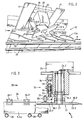
- FIGS. 2, 3 and 4 show an embodiment of the device for carrying out the method according to the invention.
- FIG. 2 shows the device 10 according to the invention seen from below, that is to say as a view against the side of a scale stream S.4 facing away from the measuring part (viewing direction according to the arrow in FIG. 3), which is fastened to fixed supports 11 arranged above the scale stream.
- the scale stream S.4 shown is a scale stream with a small scale spacing, the total thickness of which corresponds to the thickness of 2 or 3 elements at each point.
- the shingled stream is conveyed in the direction of conveyance (arrow F) by means of guide means 20 by means of transport clamps (not visible) which engage each shingled stream element, each element being slightly lifted off the guiding means 20.
- a measuring part in the form of a deflectable sensing roller 21 is arranged above the scale stream (described in detail in connection with FIG. 3).
- a reference part in the form of an impeller 22 is arranged to the side of the scale stream S.4.
- the impeller 22 has four blades 22.1 / 2/3/4 and is rotated in the direction of the arrow about an axis 23 in a plane perpendicular to the direction of the thickness measurement and parallel to the conveying direction.
- the position of the axis of rotation 23 and the impeller 22 relative to the shingled stream S.4 and the radial expansion of the vanes 22.1 / 2/3/4 are coordinated with one another such that the four reference surfaces, which are located on the surface of the vanes facing away from the viewer, when turning the impeller 22 engage so far in the scale flow that thickness measurements between the feeler roller 21 and the reference surfaces on the blades 22/1/2/3/4 are possible.
- the speed of the impeller 22 is so matched to the speed and density of the shingled stream S.4, i. H. synchronized that each element of the current is grasped by a wing and raised against the measuring part.
- the wings 21.1 / 2/3/4 in such a way that the surface facing the measuring part is beveled in the direction of rotation against the reference surface, so that the surface is gently lifted shingled flow element to be measured is effected.
- the impeller 22 is driven by a drive 25 via a shaft (not visible) which is mounted in a fixed bearing 24.
- FIG. shows the device according to Figure 2, cut perpendicular to the conveying direction and viewed in the direction of arrow III in Figure 2. Only one scale S.4x of the scale stream S.4 is visible. It is conveyed by a transport bracket 26 with the gripping elements 26.1 and 26.2.
- the impeller 22 is shown in section so that the reference surfaces 30.1 and 30.3 are visible on two vanes 22.1 and 22.3.
- the impeller 22 is arranged such that all reference surfaces 30.1 / 2/3/4 are exactly parallel to the plane spanned by the tubular guide means 20, for example.
- the reference surface 30.1 is in the measuring position opposite the feeler roller 21.
- a drive shaft 31 drives the impeller 22 and is mounted, for example, in two bearings 24.1 and 24.2.
- the drive 25 of the drive shaft 31 can be a chain drive, for example.
- the feeler roller 21 is freely rotatably mounted on a shaft 33 on a guide 34.
- the guide 34 is mounted in at least one stationary mounting (35.1 and 35.2 in FIG. 4) in such a way that it can move in the direction of the thickness of the feed stream (perpendicular to the feed direction). This movement is limited against the scale flow by an adjustable stop 36 (see FIG. 4), for example by an adjusting screw. With this stop, the zero position of the feeler roller 21 is set.
- the feeler roller 21 is pressed into its zero position by a spring 37.
- the spring 37 is prestressed between a fixed support 38 and the guide 34, the prestress being adjustable, for example, by an adjusting screw 39
- FIG. 4 shows the device according to FIGS. 2 and 3, cut parallel to the conveying direction and viewed in the direction of arrow IV in FIG. 3.
- the guide 34 to which the feeler roller 21 is fastened via the axis 33, has a lower cross part 34.1, two guide parts 34.2 and 34.3 and an upper cross part 34.4.
- the upper cross part 34.4 is composed of three individual parts 34.4 ', 34.4 "and 34.4'".
- the upper cross part 34.4 rests on the stop 36 as soon as the feeler roller 21 is in the zero position.
- the upper cross part 34.4 carries a measuring plunger 41 of a linear inductive displacement transducer 40, the housing 42 of which is fixed in place with measuring coils.
- a commercially available displacement sensor is used as the displacement sensor 40, which has a sensitivity that corresponds, for example, to the thickness of a printed page.
- the measuring output of the displacement transducer is connected to an evaluation circuit (not visible in the figures), which queries the measured value with the help of an adjustable clock generator.
- the measured value is compared with a target value which is dependent on the target thickness of the scales and on the set zero position of the feeler roller, and in the event of a deviation, a signal is transmitted to corresponding control units.
- FIGS. 2, 3 and 4 sufficiently show how the thickness measuring device discussed here is to be arranged on a scale flow so that the interaction between scale flow elements and the parts of the measuring arrangement can take place.
Landscapes
- Length Measuring Devices With Unspecified Measuring Means (AREA)
- A Measuring Device Byusing Mechanical Method (AREA)
- Measuring Arrangements Characterized By The Use Of Fluids (AREA)
- Controlling Sheets Or Webs (AREA)
- Inking, Control Or Cleaning Of Printing Machines (AREA)
- Threshing Machine Elements (AREA)
- Pharmaceuticals Containing Other Organic And Inorganic Compounds (AREA)
- Nitrogen Condensed Heterocyclic Rings (AREA)
- Measurement Of Length, Angles, Or The Like Using Electric Or Magnetic Means (AREA)
- Length Measuring Devices By Optical Means (AREA)
- Extrusion Moulding Of Plastics Or The Like (AREA)
- Handling Of Sheets (AREA)
- Fishing Rods (AREA)
Abstract
Description
Die Erfindung betrifft die Dicken-Messung von flächigen Gegenständen, beispielsweise Druckprodukten, insbesondere von in einem Schuppenstrom bewegten solchen Gegenständen, und bezieht sich auf ein Verfahren und auf eine Vorrichtung gemäss den Oberbegriffen der unabhängigen Patentansprüche.The invention relates to the thickness measurement of flat objects, for example printed products, in particular of such objects moving in a scale flow, and relates to a method and a device according to the preambles of the independent claims.
Die Dickenmessung ist eine gut anwendbare Kontrollmessung an Druckprodukten. Sie wird vorteilhafterweise am Eingang oder Ausgang von Verarbeitungsschritten oder auf Förderstrecken durchgeführt. Dabei kann beispielsweise festgestellt werden, ob an einer bestimmten Stelle des Verarbeitungsablaufes die korrekte Anzahl (beispielsweise 1) von aufeinanderliegenden Druckprodukten gefördert wird oder ob einzeln geförderte Druckprodukte die richtige Seitenzahl aufweisen, also, ob sie vollständig sind und eventuell auch, ob sie keine gefalteten oder sonstwie beschädigten Seiten enthalten. Es ist wichtig, Unregelmässigkeiten im laufenden Förderstrom möglichst sofort zu erkennen und unvollständige oder beschädigte Exemplare so früh wie möglich aus dem Verarbeitungsablauf auszuscheiden. Unregelmässigkeiten im Förderstrom führen bei der Verarbeitung mit Hochgeschwindigkeit nicht nur zu fehlerhaften Produkten, sondern können auch, wenn sie in Verarbeitungsstufen eingeführt werden, Produktionsunterbrechungen oder gar Schäden an der Maschinerie verursachen. Eine Weiterverarbeitung von schadhaften oder unvollständigen Exemplaren vermindert die Produktionsleistung, erhöht den Anfall von Makulatur und die Wahrscheinlichkeit der Auslieferung von falschen Produkten. Mit einer Kontrolle der Produkte zwischen den einzelnen Verarbeitungsstufen kann ausserdem der beteiligte Maschinenpark systematisch kontrolliert werden.Thickness measurement is a well applicable control measurement on printed products. It is advantageously carried out at the entrance or exit of processing steps or on conveyor lines. It can be determined, for example, whether the correct number (e.g. 1) of printed products lying on top of each other is being conveyed at a certain point in the processing sequence or whether individually conveyed printed products have the correct number of pages, i.e. whether they are complete and possibly also whether they are not folded or otherwise contain damaged pages. It is important to recognize irregularities in the current flow as soon as possible and to remove incomplete or damaged copies from the processing sequence as early as possible. Irregularities in the flow rate not only lead to defective products when processing at high speed, but can also cause production interruptions or even damage to the machinery if they are introduced in processing stages. Further processing of defective or incomplete copies reduces production output, increases waste and increases the likelihood of incorrect products being delivered. By checking the products between the individual processing stages, the machinery involved can also be systematically checked.
Vorrichtungen zur Messung der Dicke von Druckprodukten sind beispielsweise beschrieben in der CH-Patentschrift Nr. 660 350 derselben Anmelderin oder in den beiden DE-Offenlegungsschriften Nr. 39 13 740 und Nr. 38 23 201. Die Druckprodukte werden dabei in einer Dickenmessstelle zwischen einem Referenzteil, bspw. einer ortsfesten Rolle oder Walze, und einem auslenkbaren Messteil, bspw. einer auslenkbaren, drehenden Walze oder Rolle durchgeführt, wobei der Referenzteil auf der einen Seite des geförderten Stromes, der Messteil auf der anderen Seite angebracht ist und die beiden Teile in Ruhelage einen Abstand voneinander haben, der kleiner ist als die Dicke des Stromes. Dabei wird die Auslenkung des Messteiles gemessen und in einem Takt abgefragt, der dem Takt der durch die Messstelle geförderten Druckprodukte entspricht. Solche Vorrichtungen gemäss dem Stande der Technik, eignen sich für die Kontrolle der Regelmässigkeit des Förderstromes und/oder für die Kontrolle der einzelnen Exemplare, das heisst, sie erkennen beispielsweise ein doppeltes Exemplar in einem Förderstrom von einzelnen Exemplaren oder auch ein Exemplar, dessen Dicke nicht der Solldicke entspricht. Die Auswertung der Messresultate ist einfach, wenn es sich um einen Strom aufeinanderfolgender, einzelner Exemplare oder um einen Schuppenstrom mit grossem Schuppenabstand handelt. Unter einem Schuppenstrom mit grossem Schuppenabstand liegen die einzelnen Exemplare derart weit auseinander, dass nur die Kanten jedes Exemplars auf dem Vor-, resp. unter dem Nachexemplar liegen, während der mittlere Teil von jedem Exemplar frei liegt, das heisst, dass der Schuppenabstand A (Distanz zwischen einer Kante eines Exemplares und der entsprechenden Kante des folgenden Exemplares) grösser ist als die halbe Länge L eines Exemplares in Förderrichtung, dass also A > L/2. Es heisst auch, dass es für jedes Exemplar eine Stelle gibt, an dem die Dicke des Schuppenstromes der Exemplardicke entspricht. Nur in einem solchen Schuppenstrom mit grossem Schuppenabstand kann mit den Vorrichtungen gemäss dem Stande der Technik direkt die Dicke von jedem einzelnen Druckprodukt im Schuppenstrom gemessen werden.Devices for measuring the thickness of printed products are described, for example, in Swiss Patent No. 660 350 by the same applicant or in the two DE laid-open documents No. 39 13 740 and No. 38 23 201. The printed products are in a thickness measuring point between a reference part , for example a stationary roller or roller, and a deflectable measuring part, for example a deflectable, rotating roller or roller, the reference part being attached to one side of the conveyed stream, the measuring part on the other side and the two parts in the rest position have a distance from each other that is smaller than the thickness of the current. The deflection of the measuring part is measured and queried in a cycle that corresponds to the cycle of the printed products conveyed through the measuring point. Such devices according to the prior art are suitable for checking the regularity of the conveying flow and / or for checking the individual specimens, that is to say that they recognize, for example, a double specimen in a conveying flow of individual specimens or also a specimen whose thickness is not corresponds to the target thickness. The evaluation of the measurement results is easy if it is a stream of successive, individual specimens or a stream of shingles with a large scale spacing. Under a stream of shingles with a large distance between the sheds, the individual specimens are so far apart that only the edges of each specimen are on the fore, respectively. are below the second copy, while the middle part of each copy is free, which means that the scale distance A (distance between an edge of one copy and the corresponding edge of the following copy) is greater than half the length L of a copy in the conveying direction that thus A> L / 2. It is also said that there is a place for each specimen where the thickness of the scale flow corresponds to the specimen thickness. Only in such a scale flow with a large scale distance can the devices according to the prior art directly measure the thickness of each individual printed product in the scale flow.
Wenn Druckprodukte aber in einem Schuppenstrom mit kleinem Schuppenabstand gefördert werden, das heisst in einem Schuppenstrom, in dem der Schuppenabstand A kleiner oder gleich der halben Exemplarlänge L ist (A Z L/2), sodass an jeder Stelle des Schuppenstromes mehrere Druckprodukte aufeinander liegen, sind mit den beschriebenen Vorrichtungen, die die Dicke des ganzen Stromes messen, zwar immer noch sowohl Fehler in der Organisation des Schuppenstromes, als auch Fehler an Exemplaren feststellbar, es ist aber nicht mehr möglich, festzustellen, welches der vermessenen Exemplare fehlerhaft ist, da immer mehrere Exemplare miteinander gemessen werden. Nur mit einem beträchtlichen Rechenaufwand könnte das fehlerhafte Exemplar eventuell eruiert werden. Insbesondere sind bei Anwendung der Messvorrichtungen gemäss dem Stande der Technik auch spezielle Auswertmethoden für den Anfang und das Ende eines derartigen Schuppenstromes notwendig, denn an diesen Stellen weist er Dicken auf, die nicht "normal" sind.If, however, printed products are conveyed in a shingle stream with a small shingle spacing, i.e. in a shingle stream in which the shingle spacing A is less than or equal to half the length of the copy L (AZL / 2), so that several printed products lie on top of each other in the shingle stream, are also included The devices described, which measure the thickness of the entire stream, still detect errors in the organization of the shingled stream, as well as errors in specimens, but it is no longer possible to determine which of the measured specimens is faulty, since there are always several specimens can be measured with each other. The faulty copy could possibly only be determined with considerable computing effort. In particular, when using the measuring devices according to the prior art, special evaluation methods for the beginning and the end of such a shingled stream are also necessary, because at these points it has thicknesses that are not "normal".
Es wäre wünschenswert, ein Verfahren und/oder eine Vorrichtung zu haben, mit denen die Dicke von flächigen Gegenständen, beispielsweise Druckprodukten, die in einem Strom, insbesondere in einem Schuppenstrom mit kleinen Schuppenabständen (A Z L/2), bewegt werden, gemessen werden kann, und zwar die Dicke von einzelnen Elementen oder die Dicke jedes einzelnen Elementes des Schuppenstromes. Der Schuppenstrom soll dabei zum Zwecke der Dicken-Messung nicht umorganisiert und nicht gestoppt werden müssen. Die Auswertung der Messresultate soll für einen kontinuierlich laufenden Schuppenstrom, insbesondere für seine Anfangs- und seine Endpartie immer dieselbe sein. Die Resultate der Dickenmessung sollen verwendet werden können zur Steuerung von Mitteln zur Ausscheidung von schadhaften oder unvollständigen Exemplaren und von Partien des Schuppenstromes, die Organisationsfehler enthalten. Das Verfahren und die Vorrichtung sollen neben der Kontrolle von Schuppenströmen mit kleinem Schuppenabstand auch zur Kontrolle von Schuppenströmen mit grossem Schuppenabstand und von einzeln geförderten Druckprodukten angewendet werden können. Das Verfahren und die Vorrichtung sollen an möglichst verschiedenen Orten von Förderströmen angewendet werden können.It would be desirable to have a method and / or a device with which the thickness of flat objects, for example printed products, which are moved in a stream, in particular in a stream stream with small scale intervals (AZL / 2), can be measured, namely the thickness of individual elements or the thickness of each individual element of the shingled stream. The stream of flakes should not be reorganized and should not be stopped for the purpose of thickness measurement. The evaluation of the measurement results should always be the same for a continuously running shingled stream, especially for its beginning and end batch. The results of the thickness measurement should be able to be used to control means for the elimination of defective or incomplete specimens and of parts of the scale flow which contain organizational errors. In addition to the control of scale flows with a small scale distance, the method and the device are also intended to control scale pen streams with a large scale spacing and from individually conveyed printed products can be used. The method and the device should be able to be used at as different locations of the flow as possible.
Solch ein Verfahren bzw. eine Ausführungsform einer Vorrichtung dazu ist in den Patentansprüchen definiert. Das Verfahren und die Ausführungsform einer Vorrichtung werden anhand der folgenden Figuren detailliert beschrieben. Dabei zeigen:
- Figur 1 (a bis c) Schemata zur Erläuterung des erfindungsgemässen Verfahrens - verglichen mit einem Verfahren gemäss dem Stande der Technik - für einen Schuppenstrom mit kleinem Schuppenabstand (Fig. 1a), für einen Schuppenstrom mit grossem Schuppenabstand (Fig. 1 b) und für einen Strom einzelner Elemente (Fig. 1c),
Figur 2 eine Ansicht der bevorzugten Ausführungsform der erfindungsgemässen Vorrichtung gegen die Unterseite des Schuppenstromes gesehen,Figur 3 eine Ansicht der Vorrichtung gemässFigur 2, senkrecht zur Förderrichtung geschnitten,Figur 4 eine Ansicht der Vorrichtung gemässFigur 2, parallel zur Förderrichtung geschnitten,
- Figure 1 (a to c) schemes for explaining the inventive method - compared to a method according to the prior art - for a scale flow with a small scale distance (Fig. 1a), for a scale flow with a large scale distance (Fig. 1 b) and for a flow of individual elements (Fig. 1c),
- FIG. 2 seen a view of the preferred embodiment of the device according to the invention against the underside of the scale stream,
- FIG. 3 shows a view of the device according to FIG. 2, cut perpendicular to the conveying direction,
- FIG. 4 shows a view of the device according to FIG. 2, cut parallel to the conveying direction,
Nach dem erfindungsgemässen Verfahren wird in spezieller Weise die Dicke von flächigen Gegenständen, beispielsweise von Druckprodukten, die in einem Schuppenstrom gefördertwerden, vorzugsweise an demjenigen Teil von einzelnen Schuppenstromelementen durchgeführt, der an die Oberfläche des Schuppenstromes ragt. Dies wird erreicht durch zeitlich synchronisierte Interaktion der Messanordnung mit dem bewegten Schuppenstrom.According to the method according to the invention, the thickness of flat objects, for example of printed products, which are conveyed in a shingled stream, is preferably carried out on that part of individual shingled stream elements which protrudes from the surface of the shingled stream. This is achieved by a time-synchronized interaction of the measuring arrangement with the moving shingled stream.
Die eigentliche Dicken-Messung erfolgt zwischen einem Messteil und einem Referenzteil, wobei der Messteil in Messrichtung aus einer Nullage auslenkbar ist, durch eine entsprechende, rücktreibende Kraft aber immer in die Nullage zurückgetrieben wird, während der Referenzteil mindestens während der Messung derart positioniert ist (Messposition), dass die Distanz zwischen der Nullage des Messteiles und dem Referenzteil für alle Messungen gleich ist. Gemessen wird die Auslenkung des Messteiles. Die Dicke des vermessenen Elementes des Schuppenstromes ergibt sich aus dieser Auslenkung plus dem Abstand zwischen Referenzteil in Messposition und Messteil in Nullage. Dieser Abstand ist vorteilhafterweise einstellbar entweder durch Einstellbarkeit der Nullage des Messteiles oder der Messposition des Referenzteiles und wird kleiner eingestellt als eine minimale Dicke der zu messenden Elemente. Der Referenz- oder der Messteil können die Rolle des Interaktionsteiles übernehmen, vorzugsweise ist es der Referenzteil.The actual thickness measurement takes place between a measuring part and a reference part, whereby the measuring part can be deflected from a zero position in the measuring direction, but is always driven back into the zero position by a corresponding, pushing-back force, while the reference part is positioned at least during the measurement (measuring position ) that the distance between the zero position of the measuring part and the reference part is the same for all measurements. The deflection of the measuring part is measured. The thickness of the measured element of the scale flow results from this deflection plus the distance between the reference part in the measuring position and the measuring part in zero position. This distance can advantageously be set either by adjusting the zero position of the measuring part or the measuring position of the reference part and is set smaller than a minimum thickness of the elements to be measured. The reference part or the measuring part can assume the role of the interaction part, preferably it is the reference part.
Figuren 1a, 1b und 1c zeigen nun schematisch das erfindungsgemässe Verfahren an einem Schuppenstrom S.1 mit kleinem Schuppenabstand (A < L/2) (Fig. 1a), an einem Schuppenstrom S.2 mit grossem Schuppenabstand (A > L/2) (Fig. 1 b) und an einem Förderstrom S.3, in dem die Elemente einzeln gefördert werden (Fig. 1c). Die Darstellungen zeigen den Förderstrom über einer Zeitachse, in der sich die Dicken-Messstelle relativ zum Förderstrom bewegt. Direkt unterhalb von jedem Strom S.1/2/3 ist, auf dieselbe Zeitachse t bezogen das kontinuierliche Messsignal d der Messanordnung aufgezeigt, und zwar d.1/2/3 als Messsignal aus dem erfindungsgemässen Verfahren, d'.1/2/3 als Messsignal aus einem Messverfahren gemäss dem Stande der Technik. Die Intensität des Messsignales ist auf der Ordinate der entsprechenden Diagramme als Anzahl der gemessenen Elemente angegeben.FIGS. 1a, 1b and 1c now schematically show the method according to the invention on a scale flow S.1 with a small scale distance (A <L / 2) (FIG. 1a), on a scale flow S.2 with a large scale distance (A> L / 2) (Fig. 1 b) and on a flow S.3, in which the elements are conveyed individually (Fig. 1c). The diagrams show the flow rate over a time axis in which the thickness measuring point moves relative to the flow rate. Directly below each stream S.1 / 2/3, based on the same time axis t, the continuous measurement signal d of the measurement arrangement is shown, namely d.1 / 2/3 as a measurement signal from the method according to the invention, d'.1 / 2 / 3 as a measurement signal from a measurement method according to the prior art. The intensity of the measurement signal is indicated on the ordinate of the corresponding diagrams as the number of measured elements.
Figur 1a zeigt einen Schuppenstrom S.1 mit kleinem Schuppenabstand, in dem immer drei oder vier Elemente aufeinander liegen. Eine Dickenmessung gemäss dem Stande der Technik mit beispielsweise einem Messteil über und einem Referenzteil unter dem Schuppenstrom ergibt ein Messsignal, das immer drei oder vier Elementen entspricht und am Anfang oder Ende des Stromes stufenförmig ansteigt rsp. absinkt (d'.1). Auch wenn die Messanordnung derart empfindlich ist, dass sie beispielsweise eine fehlende Seite in einem der geförderten Druckprodukte detektieren kann, ist es doch nicht möglich, zu eruieren, in welchem der aufeinander liegenden Elemente des Schuppenstromes die Seite fehlt. Die im Schuppenstrom eingezeichneten Pfeile markieren nun die Positionen von Messteil MT und Referenzteil RT für jede Messung mit dem erfindungsgemässen Verfahren. Der Messteil befindet sich für die Messungen oberhalb des Schuppenstromes, der Referenzteil, der gleichzeitig Interaktionsteil ist, greift für jede Messung in den Schuppenstrom. Zwischen den Messungen verbleibt der Messteil in seiner Position, der Referenzteil bewegt sich aus dem Schuppenstrom, damit er für die nächste Messung wieder in den Schuppenstrom greifen kann, um die notwendige Messposition zu erreichen. Die Messpositionen, die der Referenzteil nacheinander einnimmt, sind absolut örtlich dieselben, relativ zu den Elementen des Schuppenstroms aber veränderte Positionen. Wenn der Referenzteil nicht in Messposition ist, befindet sich der Messteil in seiner Nullage. Die Interaktion des Referenzteiles mit dem Schuppenstrom besteht neben seinem Eingreifen in den Schuppenstrom darin, dass er jedes Schuppenstromelement für die Messung wenigstens teilweise vom Schuppenstrom leicht abhebt und gegen den Messteil bewegt.FIG. 1a shows a shingled stream S.1 with a small shingling spacing, in which three or four elements always lie on top of one another. A thickness measurement according to the prior art, for example with a measuring part above and a reference part below the scale flow, results in a measuring signal which always corresponds to three or four elements and increases in steps at the beginning or end of the current rsp. drops (d'.1). Even if the measuring arrangement is so sensitive that, for example, it can detect a missing page in one of the conveyed printed products, it is still not possible to determine in which of the elements of the shingled stream lying on one another the page is missing. The arrows drawn in the scale stream now mark the positions of measuring part MT and reference part RT for each measurement using the method according to the invention. For the measurements, the measuring section is located above the scale flow, the reference section, which is also an interaction section, reaches into the scale flow for each measurement. Between the measurements, the measuring part remains in its position, the reference part moves out of the shingled stream so that it can reach into the shingling stream again for the next measurement in order to reach the necessary measuring position. The measuring positions that the reference part takes one after the other are absolutely the same in their locations, but changed positions relative to the elements of the scale flow. If the reference part is not in the measuring position, the measuring part is in its zero position. The interaction of the reference part with the shingled stream consists, in addition to its intervention in the shingled stream, in that it at least partially lifts each shingled stream element from the shingled stream for the measurement and moves it against the measuring part.
Der Messwert wird getaktet abgefragt (Pfeile unter dem Schema d/t), derart, dass der Takt der Abfragung dem Takt der Bewegung des Referenzteiles entspricht und dass dann abgefragt wird, wenn der Referenzteil sich in Messposition befindet. Der rechte Teil des Schemas zeigt deutlich, dass am Anfang und am Ende des Schuppenstromes dasselbe Signal anfällt wie für die mittlere Partie des Schuppenstromes. Entspricht ein Messsignal nicht dem Sollwert, ist das vermessene Schuppenstromelement beispielsweise doppelt, schadhaft oder unvollständig und ist durch den Zeitpunkt des Messsignales eindeutig identifiziert. Je nach Synchronisation des Taktes mit dem Schuppenstrom wird jedes einzelne Element oder werden einzelne Elemente in einer regelmässigen Sequenz gemessen.The measured value is queried in a clocked manner (arrows under the scheme d / t) in such a way that the clock of the query corresponds to the clock of the movement of the reference part and that it is queried when the reference part is in the measurement position. The right part of the diagram clearly shows that at the beginning and at the end of the Scale signal the same signal occurs as for the middle section of the scale flow. If a measurement signal does not correspond to the setpoint, the measured scale flow element is, for example, double, defective or incomplete and is clearly identified by the time of the measurement signal. Depending on the synchronization of the cycle with the shingled stream, each individual element or individual elements are measured in a regular sequence.
Figur 1b zeigt das gleiche Schema wie Figur 1a, aber für einen Schuppenstrom S.2 mit grossem Schuppenabstand, Figur 1c für einen Förderstrom einzelner Elemente S.3. Es ist aus den beiden Figuren, speziell aus einem Vergleich der beiden Signalverläufe d.2, d'.2 und d.3, d'.3 ersichtlich, dass das erfindungsgemässe Verfahren (Signale d.2, d.3) zwar ebenfalls anwendbar ist, dass es aber gegenüber dem Verfahren gemäss dem Stande der Technik (Signale d'.2, d'.3) keine speziellen Vorteile erbringt. Mit den Pfeilen unter dem Messsignal d'.2 und d'.3 sind die Zeitpunkte angegeben, an denen das Messsignal abgefragt werden muss, damit jeweils nur ein Element gemessen wird.Figure 1b shows the same scheme as Figure 1a, but for a scale flow S.2 with a large scale distance, Figure 1c for a flow of individual elements S.3. It can be seen from the two figures, specifically from a comparison of the two signal profiles d.2, d'.2 and d.3, d'.3, that the method according to the invention (signals d.2, d.3) can also be used is that it has no special advantages over the method according to the state of the art (signals d'.2, d'.3). The arrows below the measurement signal d'.2 and d'.3 indicate the times at which the measurement signal must be queried so that only one element is measured at a time.
Das erfindungsgemässe Dicken-Messverfahren besteht also im wesentlichen darin, dass der durch ein Schuppenstromelement erzeugte Abstand zwischen einem ausserhalb des Schuppenstromes angeordneten Teil der Messanordnung und einem mit dem Schuppenstrom in Interaktion tretenden Teil der Messanordnung (Interaktionsteil) gemessen wird. Bevorzugterweise ist der Messteil ausserhalb des Schuppenstromes quasi stationär angeordnet, während der Referenzteil als Interaktion-Teil derart beweglich ist, dass sich wenigstens Teile von ihm zwischen Positionen innerhalb und ausserhalb vom Schuppenstrom bewegen. Anordnungen mit stationärem Referenzteil und bewegtem Messteil als Interaktionsteil sind aber ebenfalls denkbar.The thickness measurement method according to the invention essentially consists in measuring the distance generated by a scale flow element between a part of the measuring arrangement arranged outside the scale flow and a part of the measuring arrangement (interaction part) which interacts with the scale flow. Preferably, the measuring part is arranged quasi-stationary outside the scale flow, while the reference part as an interaction part is movable in such a way that at least parts of it move between positions inside and outside the scale flow. Arrangements with a stationary reference part and a moving measuring part as an interaction part are also conceivable.
In der bevorzugten Verfahrensvariante greift der Referenzteil seitlich in den Schuppenstrom und zwar zwischen das an der Oberfläche liegende Element des Schuppenstromes und den Rest des Schuppenstromes, wie dies in den Figuren 1 und 1 dargestellt ist. Eine Verfahrensvariante besteht darin, dass der bewegliche Teil der Messanordnung nicht von der Seite, sondern von der Oberfläche des Schuppenstromes unter die einzelnen Elemente greift. Ein solches Verfahren ist insbesondere für Schuppenströme von gefalteten Druckprodukten an derjenigen Oberfläche, an der die Falze liegen, anwendbar.In the preferred variant of the method, the reference part engages laterally in the scale flow, namely between the surface element of the scale flow and the rest of the scale flow, as shown in FIGS. 1 and 1. One method variant is that the movable part of the measuring arrangement does not reach under the individual elements from the side but from the surface of the scale flow. Such a method can be used in particular for imbricated flows of folded printed products on the surface on which the folds are located.
Da der eine Teil der Messanordnung zwischen die Elemente des Schuppenstromes greift, lässt sich eine gewisse Reibung zwischen diesen Elementen und dem Teil der Messanordnung nicht verhindern. Durch diese Reibung entsteht eine Kraft auf die Schuppenstromelemente, die diese von ihrem ordentlichen Platz im Schuppenstrom zu bewegen versucht. Es ist deshalb vorteilhaft, die Dicken-Messung an Orten zu installieren, an denen die einzelnen Schuppen eventuell auch aus anderen Gründen durch entsprechende Mittel, wie beispielsweise Klammern, auf ihrem Platz gehalten werden, oder speziell für die Dicken-Messung solche Mittel an der entsprechenden Stelle der Förderstrecke zu installieren. Für Schuppenströme, die mit einem getakteten Förderverfahren mit automatischer Regenerierung der Schuppenordnung in Förderrichtung gefördert werden, genügen als Gegenhalt gegen die Reibungskraft seitlich vom Schuppenstrom angeordnete Führungen. Ein entsprechendes, getaktetes Förderverfahren ist beispielsweise beschrieben in der CH-Anmeldung 1697/90 derselben Anmelderin. Höchstens in Fällen von eher schweren, grossflächigen Schuppenstromelementen, die schlecht aufeinander rutschen, könnte der Interaktions-Teil der Messanordnung unter Umständen ohne einen Gegenhalt unter das zu vermessende Element greifen, ohne dass dieses sich aus seiner exakten Position im Schuppenstrom bewegt.Since one part of the measuring arrangement reaches between the elements of the scale flow, a certain amount of friction between these elements and the part of the measuring arrangement cannot be prevented. This friction creates a force on the shingled stream elements that tries to move them from their proper place in the shingled stream. It is therefore advantageous to install the thickness measurement at locations where the individual scales may be held in place for other reasons by appropriate means, such as, for example, clamps, or such means at the corresponding location, especially for the thickness measurement To install the conveyor line. For scale flows, which are conveyed in the conveying direction with a clocked conveying method with automatic regeneration of the scale order, guides arranged laterally from the scale flow are sufficient as a countermeasure against the frictional force. A corresponding, timed funding procedure is described, for example, in CH application 1697/90 by the same applicant. At most, in cases of rather heavy, large-scale scale flow elements that do not slide well against one another, the interaction part of the measuring arrangement could reach under the element to be measured under certain circumstances without any support, without the element moving from its exact position in the scale flow.
Wird das erfindungsgemässe Vefahren zur Dicken-Messung für einen Strom von einzeln geförderten Elementen angewendet, so greift der Interaktions-Teil der Messanordnung nicht zwischen zwei Elemente des Stromes sondern zwischen jedes einzelne Element und die Unterlage des Stromes.If the method according to the invention is used for thickness measurement for a stream of individually conveyed elements, the interaction part of the measuring arrangement does not reach between two elements of the stream but between each individual element and the base of the stream.
Für die bevorzugte Verfahrensvariante wird die Messung durchgeführt an einem Schuppenstrom, dessen Elemente einzeln von beispielsweise Klammern über eine Unterlage gefördert werden. Die Klammern greifen an demjenigen Teil des Elementes an, der an der Oberfläche des Schuppenstromes liegt, und heben diesen leicht aus seiner Lage im Schuppenstrom ab. Der vorgeschlagene Messteil besteht aus einer aus einer Nullage gefedert gegen oben auslenkbaren frei drehbaren Rolle (Tastrolle), die unmittelbar über der durch die Klammern aus dem Schuppenstrom abgehobenen Kante der Schuppenstromelemente angeordnet ist. Der vorgeschlagene Referenzteil, der auch die Rolle des Interaktions-Teils übernimmt, ist seitlich vom Schuppenstrom angeordnet und weist mindestens eine Referenzfläche auf, die für die Messung zwischen das zu messende, oberste Schuppenstromelement und den Rest des Schuppenstromes geschoben wird, derart, dass während einer sehr kurzen Zeit ein Teil jedes Elementes zwischen der Referenzfläche (in Messposition) und der Tastrolle durchgeführt wird. Während dieser Zeit wird das Signal der Auslenkung der Tastrolle abgefragt. Zwischen zwei Messungen wird die Referenzfläche aus ihrer Messposition bewegt, sodass sie sich unter das nächste Element (über dem bereits vermessenen Element) schieben kann. Die getaktete Bewegung der Referenzfläche und die getaktete Abfrage der Auslenkung der Tastrolle sind aufeinander und auf die Dichte des Schuppenstromes (Schuppenabstand) und auf dessen Geschwindigkeit abgestimmt, derart, dass jedes Schuppenstromelement an derselben Stelle vermessen wird.For the preferred method variant, the measurement is carried out on a scale stream, the elements of which are conveyed individually by, for example, clamps over a base. The brackets grip the part of the element that lies on the surface of the scale stream and lift it slightly out of its position in the scale stream. The proposed measuring part consists of a freely rotatable roller (tracer roller), which is spring-loaded from a zero position and can be deflected upward and which is arranged directly above the edge of the shingled stream elements lifted from the shingled stream by the brackets. The proposed reference part, which also takes on the role of the interaction part, is arranged to the side of the scale stream and has at least one reference surface which is pushed between the uppermost scale stream element to be measured and the rest of the scale stream, in such a way that during a a very short time a part of each element is carried out between the reference surface (in measuring position) and the feeler roller. During this time, the signal of the deflection of the sensing roller is queried. Between two measurements, the reference surface is moved from its measuring position so that it can slide under the next element (above the element already measured). The clocked movement of the reference surface and the clocked query of the deflection of the sensing roller are matched to one another and to the density of the scale flow (scale distance) and its speed, such that each scale flow element is measured at the same point.
Die Referenzfläche des Referenzteiles bewegt sich, vorteilhafterweise mit konstanter Geschwindigkeit, auf einer geschlossenen Bahn, die im wesentlichen in der Ebene des Schuppenstromes verläuft, und durchläuft auf jedem Umgang die Messposition zwischen den Schuppenstromelementen. Die Ausgestaltung der Referenzfläche und ihre Bewegung müssen derart aufeinander abgestimmt sein, dass die Zeit, in der sich ein Teil der Referenzfläche in Messposition befindet, mindestens der Zeit entspricht, die für eine Messung notwendig ist. Es können auch mehrere Referenzflächen zurAnwendung kommen, die sich auf einer im wesentlichen gleichen geschlossenen Bahn bewegen und die Messposition nacheinander erreichen, derart, dass mit Hilfe von einer der Referenzflächen beispielsweise nur jede vierte Messung ausgeführt wird.The reference surface of the reference part moves, advantageously at a constant speed, on a closed path which essentially runs in the plane of the scale flow, and passes through the measuring position between the scale flow elements on every handling. The design of the reference surface and its movement must be coordinated with one another in such a way that the time in which a part of the reference surface is in the measuring position corresponds at least to the time required for a measurement. A plurality of reference surfaces can also be used, which move on a substantially identical closed path and reach the measuring position one after the other, such that, for example, only one in four measurements is carried out with the aid of one of the reference surfaces.
Auch eine lineare Hin- und Zurückbewegung der Referenzfläche ist denkbar, wobei die Referenzfläche dann für die effektive Messung stillsteht und zwischen den Messungen zweimal beschleunigt und wieder abgebremst werden muss.A linear back and forth movement of the reference surface is also conceivable, the reference surface then standing still for the effective measurement and having to be accelerated and decelerated twice between measurements.
Die zur Durchführung des erfindungsgemässen Verfahrens verwendete Vorrichtung weist im wesentlichen die folgenden Bestandteile auf: einen Referenzteil, einen auslenkbarer Messteil mit Nullage und mit Kraftmitteln, die ihn in die Nullage treiben, einen Sensor, der die Auslenkung des Messteiles misst und eine Auswertungseinheit, die das Messsignal des Sensors getaktet abfragt, mit einem Sollwert vergleicht und ein aus dem Vergleich entstehendes Signal weiterleitet. Dabei ist der Messteil oder der Referenzteil derart beweglich, dass er die Interaktion mit dem Schuppenstrom übernehmen, das heisst, sich für die Messung zwischen die Elemente des Schuppenstromes oder zwischen die Elemente des Schuppenstromes und die Unterlage schieben kann, während der andere Teil stationär unmittelbar ausserhalb des Schuppenstromes angeordnet ist. Es ist vorteilhaft, wenn entweder die Messposition des Referenzteiles oder die Nullage des Messteiles einstellbar ist. Der Sensor und die Auswertungseinheit sind handelsübliche Baueinheiten und werden in der folgenden Beschreibung nicht detailliert beschrieben.The device used to carry out the method according to the invention essentially has the following components: a reference part, a deflectable measuring part with zero position and with force means that drive it into the zero position, a sensor that measures the deflection of the measuring part and an evaluation unit that does this Interrogates the measuring signal of the sensor in a clocked manner, compares it with a target value and forwards a signal resulting from the comparison. The measuring part or the reference part is movable in such a way that it takes over the interaction with the shingled stream, i.e. it can slide between the elements of the shingling stream or between the elements of the shingling stream and the support for the measurement, while the other part is stationary directly outside of the scale stream is arranged. It is advantageous if either the measuring position of the reference part or the zero position of the measuring part can be set. The sensor and the evaluation unit are commercially available units and are not described in detail in the following description.
In den Figuren 2, 3 und 4 ist eine Ausführungsform der Vorrichtung zur Durchführung des erfindungsgemässen Verfahrens dargestellt.FIGS. 2, 3 and 4 show an embodiment of the device for carrying out the method according to the invention.
Figur 2 zeigt die erfindungsgemässe Vorrichtung 10 von unten gesehen, das heisst, als Ansicht gegen die vom Messteil abgewandte Seite eines Schuppenstromes S.4 (Betrachtungsrichtung gemäss Pfeil in Figur 3), die an über dem Schuppenstrom angeordneten ortsfesten Trägern 11 befestigt ist. Der abgebildete Schuppenstrom S.4 ist ein Schuppenstrom mit kleinem Schuppenabstand, dessen totale Dicke an jeder Stelle der Dicke von 2 oder 3 Elementen entspricht. Der Schuppenstrom wird durch Transportklammern (nicht sichtbar), die an jedem Schuppenstromelement angreifen, in Förderrichtung (Pfeil F) über Führungsmittel 20 gefördert, wobei jedes Element leicht von den Führungsmitteln 20 abgehoben wird. Über dem Schuppenstrom ist ein Messteil in Form einer auslenkbaren Tastrolle 21 angeordnet (im Zusammenhang mit der Figur 3 detailliert beschrieben). Seitlich vom Schuppenstrom S.4 ist ein Referenzteil in Form eines Flügelrades 22 angeordnet. Das Flügelrad 22 weist in diesem Beispiel vier Flügel 22.1/2/3/4 auf und wird in Pfeilrichtung um eine Achse 23 in einer Ebene senkrecht zur Richtung der Dicken-Messung und parallel zur Förderrichtung gedreht. Die Position der Drehachse 23 und des Flügelrades 22 relativ zum Schuppenstrom S.4 und die radiale Ausdehnung der Flügel 22.1/2/3/4 sind derart aufeinander abgestimmt, dass die vier Referenzflächen, die sich auf der vom Betrachter abgewandten Oberfläche der Flügel befinden, beim Drehen des Flügelrades 22 so weit in den Schuppenstrom eingreifen, dass Dickenmessungen zwischen der Tastrolle 21 und den Referenzflächen auf den Flügeln 22/1/2/3/4 möglich sind. Die Drehzahl des Flügelrades 22 ist derart auf die Geschwindigkeit und die Dichte des Schuppenstromes S.4 abgestimmt, d. h. synchronisiert, dass jedes Element des Stromes von einem Flügel erfasst und gegen den Messteil gehoben wird. Damit diese Bewegung gleichmässig und ohne das zu messende Schuppenstromelement zu beschädigen ablaufen kann, ist es vorteilhaft, die Flügel 21.1/2/3/4 derart auszugestalten, dass die dem Messteil zugewandte Oberfläche in Drehrichtung gegen die Referenzfläche abgeschrägt ist, sodass ein sanftes Anheben des zu vermessenden Schuppenstromelementes bewirkt wird. Das Flügelrad 22 wird über eine Welle (nicht sichtbar), die in einer ortsfesten Lagerung 24 gelagert ist, von einem Antrieb 25 angetrieben.FIG. 2 shows the
Die Förderrichtung kann auch dem Pfeil F entgegengesetzt sein. Das Flügelrad kann auch eine andere Anzahl von Flügeln aufweisen.The direction of conveyance can also be opposite to the arrow F. The impeller can also have a different number of blades.
Figur zeigt die Vorrichtung gemäss Figur2, senkrecht zur Förderrichtung geschnitten und in der Richtung des Pfeiles III in Figur 2 betrachtet. Vom Schuppenstrom S.4 ist nur eine Schuppe S.4x sichtbar. Sie wird durch eine Transportklammer 26 mit den Greifelementen 26.1 und 26.2 gefördert. Das Flügelrad 22 ist geschnitten dargestellt, sodass auf zwei Flügeln 22.1 und 22.3 die Referenzflächen 30.1 und 30.3 sichtbar werden. Das Flügelrad 22 ist derart angeordnet, dass alle Referenzflächen 30.1/2/3/4 genau parallel zu der von den beispielsweise rohrförmigen Führungsmitteln 20 aufgespannten Ebene liegen. Die Referenzfläche 30.1 befindet sich in Messposition gegenüber der Tastrolle 21. Eine Antriebswelle 31 treibt das Flügelrad 22 an und ist beispielsweise in zwei Lagern 24.1 und 24.2 gelagert. Der Antrieb 25 der Antriebswelle 31 kann beispielsweise ein Kettenantrieb sein.Figure shows the device according to Figure 2, cut perpendicular to the conveying direction and viewed in the direction of arrow III in Figure 2. Only one scale S.4x of the scale stream S.4 is visible. It is conveyed by a
Die Tastrolle 21 ist frei auf einer Welle 33 drehend an einer Führung 34 befestigt. Die Führung 34 ist in mindestens einer ortsfest montierten Lagerung (35.1 und 35.2 in Fig. 4) derart gelagert, dass sie sich in der Richtung der Dicke des Förderstromes (senkrecht zur Förderrichtung) bewegen kann. Diese Bewegung wird gegen den Schuppenstrom begrenzt durch einen einstellbaren Anschlag 36 (siehe Figur 4), beispielsweise durch eine Stellschraube. Mit diesem Anschlag wird die Nullage der Tastrolle 21 eingestellt. Die Tastrolle 21 wird durch eine Feder 37 in ihre Nullage gedrückt. Die Feder 37 ist zwischen einem ortsfesten Widerhalt 38 und der Führung 34 vorgespannt, wobei die Vorspannung durch beispielsweise eine Stellschraube 39 einstellbar sein kannThe
Figur 4 zeigt die Vorrichtung gemäss Figuren 2 und 3, parallel zur Förderrichtung geschnitten und in der Richtung des Pfeiles IV in Figur 3 betrachtet. Aus Figur4 ist ersichtlich, dass die Führung 34, an der die Tastrolle 21 über die Achse 33 befestigt ist, einen unteren Querteil 34.1, zwei Führungsteile 34.2 und 34.3 und einen oberen Querteil 34.4 aufweist. Der obere Querteil 34.4 ist in dieser Ausführungsform aus drei Einzelteilen 34.4', 34.4" und 34.4'" zusammengesetzt. Der obere Querteil 34.4 liegt auf dem Anschlag 36 auf, sobald die Tastrolle 21 in der Nullage ist. Der obere Querteil 34.4 trägt einen Messstössel 41 eines linearen induktiven Wegaufnehmers 40, dessen Gehäuse 42 mit Messspulen ortsfest angebracht ist. Als Wegaufnehmer 40 wird ein handelsüblicher Wegaufnehmer verwendet, der eine Empfindlichkeit aufweist, die beispielsweise der Dicke einer Druckseite entspricht.FIG. 4 shows the device according to FIGS. 2 and 3, cut parallel to the conveying direction and viewed in the direction of arrow IV in FIG. 3. It can be seen from FIG. 4 that the
Der Messausgang des Wegaufnehmers ist an eine Auswertschaltung (in den Figuren nicht sichtbar) angeschlossen, die mit Hilfe eines einstellbaren Taktgebers im notwendigen Takt den Messwert abfragt. Der Messwert wird mit einem von der Solldicke der Schuppen und von der eingestellten Nullage der Tastrolle abhängigen Sollwert verglichen und im Falle einer Abweichung wird ein Signal an entsprechende Steuereinheiten übergeben.The measuring output of the displacement transducer is connected to an evaluation circuit (not visible in the figures), which queries the measured value with the help of an adjustable clock generator. The measured value is compared with a target value which is dependent on the target thickness of the scales and on the set zero position of the feeler roller, and in the event of a deviation, a signal is transmitted to corresponding control units.
Die Figuren 2, 3 und 4 zeigen in ausreichender Weise, wie die hier diskutierte Dicken-Messvorrichtung an einem Schuppenstrom angeordnet sein soll, damit die Interaktion zwischen Schuppenstromelementen und den Teilen der Messanordnung stattfinden kann.FIGS. 2, 3 and 4 sufficiently show how the thickness measuring device discussed here is to be arranged on a scale flow so that the interaction between scale flow elements and the parts of the measuring arrangement can take place.
Claims (16)
Applications Claiming Priority (2)
| Application Number | Priority Date | Filing Date | Title |
|---|---|---|---|
| CH323190 | 1990-10-05 | ||
| CH3231/90 | 1990-10-05 |
Publications (2)
| Publication Number | Publication Date |
|---|---|
| EP0479717A1 true EP0479717A1 (en) | 1992-04-08 |
| EP0479717B1 EP0479717B1 (en) | 1995-03-22 |
Family
ID=4251485
Family Applications (1)
| Application Number | Title | Priority Date | Filing Date |
|---|---|---|---|
| EP91810672A Expired - Lifetime EP0479717B1 (en) | 1990-10-05 | 1991-08-22 | Device for measuring the thickness of printed products in a shingled formation |
Country Status (10)
| Country | Link |
|---|---|
| US (1) | US5154279A (en) |
| EP (1) | EP0479717B1 (en) |
| JP (1) | JP3100195B2 (en) |
| AT (1) | ATE120153T1 (en) |
| AU (1) | AU650898B2 (en) |
| CA (1) | CA2051244A1 (en) |
| DE (1) | DE59104989D1 (en) |
| ES (1) | ES2073152T3 (en) |
| FI (1) | FI101902B (en) |
| RU (1) | RU2069305C1 (en) |
Cited By (1)
| Publication number | Priority date | Publication date | Assignee | Title |
|---|---|---|---|---|
| EP1661833A1 (en) | 2004-11-26 | 2006-05-31 | Ferag AG | Method and device for treating printed products |
Families Citing this family (6)
| Publication number | Priority date | Publication date | Assignee | Title |
|---|---|---|---|---|
| ES2084260T3 (en) * | 1992-02-19 | 1996-05-01 | Ferag Ag | DOUBLE BLADE RECOGNITION. |
| EP0568883B1 (en) * | 1992-05-07 | 1995-08-30 | Ferag AG | Management system for faults in overlapping formations of printed products |
| EP0651231B1 (en) * | 1993-10-29 | 1997-06-18 | Ferag AG | Procedure and device to measure the thickness of printed matter, like papers, magazines and parts thereof |
| US6313414B1 (en) | 2000-01-31 | 2001-11-06 | Harvestmaster, Inc. | Slope and motion compensator for weighing on a dynamic platform |
| US7981388B2 (en) * | 2004-08-23 | 2011-07-19 | Air Products And Chemicals, Inc. | Process for the purification of lithium salts |
| US7465517B2 (en) * | 2004-08-23 | 2008-12-16 | Air Products And Chemicals, Inc. | High purity lithium polyhalogenated boron cluster salts useful in lithium batteries |
Citations (3)
| Publication number | Priority date | Publication date | Assignee | Title |
|---|---|---|---|---|
| DE870422C (en) * | 1940-10-10 | 1953-03-12 | Bobst & Sohn A G J | Method and device for securing the isolated delivery of sheets conveyed as a flaky sheet path |
| GB1094863A (en) * | 1964-04-23 | 1967-12-13 | Roland Offsetmaschf | Detecting devices for sheet printing presses |
| DE3419436A1 (en) * | 1983-06-14 | 1984-12-20 | Ferag AG, Hinwil, Zürich | DEVICE FOR DETERMINING MULTIPLE-USED SPACE IN A CONTINUOUSLY REQUIRED CURRENT OF UNIFORM PRESSURE PRODUCTS AND THE USE OF THIS DEVICE |
Family Cites Families (6)
| Publication number | Priority date | Publication date | Assignee | Title |
|---|---|---|---|---|
| US2312357A (en) * | 1940-03-02 | 1943-03-02 | American Can Co | Sorting machine |
| DE3234471C1 (en) * | 1982-09-17 | 1983-08-25 | Dr. Johannes Heidenhain Gmbh, 8225 Traunreut | Multi-coordinate probe |
| ATE55965T1 (en) * | 1988-01-13 | 1990-09-15 | Ferag Ag | METHOD AND DEVICE FOR CHANGING THE DEGREE OF OVERLAP OF PRINTING PRODUCTS CONVEYED IN A SHINGLE STREAM. |
| JP2567279B2 (en) * | 1988-04-26 | 1996-12-25 | ローレルバンクマシン株式会社 | Sheet thickness detector |
| DE3823201A1 (en) * | 1988-07-08 | 1988-12-08 | Mabeg Maschinenbau Gmbh Nachf | Multiple sheet monitoring device |
| US5158277A (en) * | 1990-05-21 | 1992-10-27 | SFT AG Spontanfordertichnik | Method and apparatus for conveying printed products |
-
1991
- 1991-08-22 ES ES91810672T patent/ES2073152T3/en not_active Expired - Lifetime
- 1991-08-22 DE DE59104989T patent/DE59104989D1/en not_active Expired - Fee Related
- 1991-08-22 AT AT91810672T patent/ATE120153T1/en not_active IP Right Cessation
- 1991-08-22 EP EP91810672A patent/EP0479717B1/en not_active Expired - Lifetime
- 1991-08-27 AU AU82751/91A patent/AU650898B2/en not_active Ceased
- 1991-09-03 US US07/754,021 patent/US5154279A/en not_active Expired - Lifetime
- 1991-09-12 CA CA002051244A patent/CA2051244A1/en not_active Abandoned
- 1991-09-24 FI FI914479A patent/FI101902B/en active
- 1991-10-04 JP JP03257723A patent/JP3100195B2/en not_active Expired - Fee Related
- 1991-10-04 RU SU915001767A patent/RU2069305C1/en active
Patent Citations (3)
| Publication number | Priority date | Publication date | Assignee | Title |
|---|---|---|---|---|
| DE870422C (en) * | 1940-10-10 | 1953-03-12 | Bobst & Sohn A G J | Method and device for securing the isolated delivery of sheets conveyed as a flaky sheet path |
| GB1094863A (en) * | 1964-04-23 | 1967-12-13 | Roland Offsetmaschf | Detecting devices for sheet printing presses |
| DE3419436A1 (en) * | 1983-06-14 | 1984-12-20 | Ferag AG, Hinwil, Zürich | DEVICE FOR DETERMINING MULTIPLE-USED SPACE IN A CONTINUOUSLY REQUIRED CURRENT OF UNIFORM PRESSURE PRODUCTS AND THE USE OF THIS DEVICE |
Cited By (1)
| Publication number | Priority date | Publication date | Assignee | Title |
|---|---|---|---|---|
| EP1661833A1 (en) | 2004-11-26 | 2006-05-31 | Ferag AG | Method and device for treating printed products |
Also Published As
| Publication number | Publication date |
|---|---|
| JP3100195B2 (en) | 2000-10-16 |
| FI914479A0 (en) | 1991-09-24 |
| AU8275191A (en) | 1992-04-09 |
| EP0479717B1 (en) | 1995-03-22 |
| DE59104989D1 (en) | 1995-04-27 |
| AU650898B2 (en) | 1994-07-07 |
| FI914479A (en) | 1992-04-06 |
| CA2051244A1 (en) | 1992-04-06 |
| US5154279A (en) | 1992-10-13 |
| FI101902B1 (en) | 1998-09-15 |
| ATE120153T1 (en) | 1995-04-15 |
| ES2073152T3 (en) | 1995-08-01 |
| FI101902B (en) | 1998-09-15 |
| JPH04297818A (en) | 1992-10-21 |
| RU2069305C1 (en) | 1996-11-20 |
Similar Documents
| Publication | Publication Date | Title |
|---|---|---|
| DE4241502C2 (en) | Apparatus for continuously feeding individual sheets to a sheet processing section of a sheet processing device | |
| EP0431267B1 (en) | Sheet aligning device | |
| DE2118587C3 (en) | Device for the mutual adjustment of the conveying speeds of two conveyors | |
| WO2009015714A1 (en) | Alignment of food products | |
| EP2030924A1 (en) | Device for processing printed products | |
| DE3220629C2 (en) | Control device for gluing endless sets | |
| AT394157B (en) | DEVICE FOR DETERMINING MULTIPLE-USED SPACE IN A CONTINUOUS FLOW OF PRINTED PRODUCTS CONTAINED IN EVEN DISTANCES | |
| EP1252082B1 (en) | Device and method for detecting paper sheets | |
| EP0556486B1 (en) | Double sheet detector | |
| EP0479717B1 (en) | Device for measuring the thickness of printed products in a shingled formation | |
| AT522235B1 (en) | Conveyor device for gapless and pressureless or low-pressure accumulation of objects and operating methods therefor | |
| CH712435A2 (en) | Method and device for aligning a metal sheet during the feeding of the metal sheet to a processing station, in particular to a stamping press. | |
| EP1421022B1 (en) | Method and device for identifying double feeds | |
| DE4210957A1 (en) | Method for monitoring the transport of printed products in a printing machine | |
| DE102017120730A1 (en) | Device and method for aligning containers | |
| EP0731046A2 (en) | Device for synchronising sheet feeding | |
| DE102019210959A1 (en) | Weighing device and method for weighing a portion of food on support elements | |
| DE60125151T2 (en) | MEASURING AND CONTROL SYSTEM FOR CUTTING LENGTHS OF ITEMS IN A HIGH-SPEED PROCESS | |
| DE3730683A1 (en) | Process and device for monitoring articles | |
| EP2935060B1 (en) | Device and method for rotating flat goods | |
| DE102018130149B4 (en) | Plant for a sheet-like substrate processing machine and method for operating a plant | |
| DE2947709A1 (en) | SYSTEM FOR FEEDING SHEETS FROM A STACK | |
| DE102012112718A1 (en) | Apparatus and method for turning flat goods | |
| DE60125231T2 (en) | APPARATUS AND METHOD FOR DETERMINING OVERLAPPING OBJECTS | |
| DE102017222372A1 (en) | Apparatus and method for winding a belt construction strip suitable for making a belt of a pneumatic vehicle tire on a belt building drum |
Legal Events
| Date | Code | Title | Description |
|---|---|---|---|
| PUAI | Public reference made under article 153(3) epc to a published international application that has entered the european phase |
Free format text: ORIGINAL CODE: 0009012 |
|
| AK | Designated contracting states |
Kind code of ref document: A1 Designated state(s): AT CH DE ES FR GB IT LI NL SE |
|
| 17P | Request for examination filed |
Effective date: 19920307 |
|
| 17Q | First examination report despatched |
Effective date: 19931125 |
|
| ITF | It: translation for a ep patent filed |
Owner name: DE DOMINICIS & MAYER S.R.L. |
|
| GRAA | (expected) grant |
Free format text: ORIGINAL CODE: 0009210 |
|
| AK | Designated contracting states |
Kind code of ref document: B1 Designated state(s): AT CH DE ES FR GB IT LI NL SE |
|
| REF | Corresponds to: |
Ref document number: 120153 Country of ref document: AT Date of ref document: 19950415 Kind code of ref document: T |
|
| GBT | Gb: translation of ep patent filed (gb section 77(6)(a)/1977) |
Effective date: 19950316 |
|
| ET | Fr: translation filed | ||
| REF | Corresponds to: |
Ref document number: 59104989 Country of ref document: DE Date of ref document: 19950427 |
|
| REG | Reference to a national code |
Ref country code: ES Ref legal event code: FG2A Ref document number: 2073152 Country of ref document: ES Kind code of ref document: T3 |
|
| PLBE | No opposition filed within time limit |
Free format text: ORIGINAL CODE: 0009261 |
|
| STAA | Information on the status of an ep patent application or granted ep patent |
Free format text: STATUS: NO OPPOSITION FILED WITHIN TIME LIMIT |
|
| 26N | No opposition filed | ||
| PGFP | Annual fee paid to national office [announced via postgrant information from national office to epo] |
Ref country code: AT Payment date: 19970813 Year of fee payment: 7 |
|
| PGFP | Annual fee paid to national office [announced via postgrant information from national office to epo] |
Ref country code: ES Payment date: 19970829 Year of fee payment: 7 |
|
| PGFP | Annual fee paid to national office [announced via postgrant information from national office to epo] |
Ref country code: NL Payment date: 19970831 Year of fee payment: 7 |
|
| PG25 | Lapsed in a contracting state [announced via postgrant information from national office to epo] |
Ref country code: AT Free format text: LAPSE BECAUSE OF NON-PAYMENT OF DUE FEES Effective date: 19980822 |
|
| PG25 | Lapsed in a contracting state [announced via postgrant information from national office to epo] |
Ref country code: ES Free format text: LAPSE BECAUSE OF EXPIRATION OF PROTECTION Effective date: 19980824 |
|
| PG25 | Lapsed in a contracting state [announced via postgrant information from national office to epo] |
Ref country code: NL Free format text: LAPSE BECAUSE OF NON-PAYMENT OF DUE FEES Effective date: 19990301 |
|
| NLV4 | Nl: lapsed or anulled due to non-payment of the annual fee |
Effective date: 19990301 |
|
| REG | Reference to a national code |
Ref country code: ES Ref legal event code: FD2A Effective date: 20010201 |
|
| REG | Reference to a national code |
Ref country code: GB Ref legal event code: IF02 |
|
| REG | Reference to a national code |
Ref country code: CH Ref legal event code: PFA Owner name: FERAG AG Free format text: FERAG AG#ZUERICHSTRASSE 74#8340 HINWIL (CH) -TRANSFER TO- FERAG AG#PATENTABTEILUNG Z. H. MARKUS FELIX ZUERICHSTRASSE 74#8340 HINWIL (CH) |
|
| PGFP | Annual fee paid to national office [announced via postgrant information from national office to epo] |
Ref country code: CH Payment date: 20050714 Year of fee payment: 15 |
|
| PGFP | Annual fee paid to national office [announced via postgrant information from national office to epo] |
Ref country code: SE Payment date: 20050811 Year of fee payment: 15 |
|
| PGFP | Annual fee paid to national office [announced via postgrant information from national office to epo] |
Ref country code: DE Payment date: 20050812 Year of fee payment: 15 Ref country code: FR Payment date: 20050812 Year of fee payment: 15 |
|
| PGFP | Annual fee paid to national office [announced via postgrant information from national office to epo] |
Ref country code: GB Payment date: 20050816 Year of fee payment: 15 |
|
| PG25 | Lapsed in a contracting state [announced via postgrant information from national office to epo] |
Ref country code: SE Free format text: LAPSE BECAUSE OF NON-PAYMENT OF DUE FEES Effective date: 20060823 |
|
| PG25 | Lapsed in a contracting state [announced via postgrant information from national office to epo] |
Ref country code: LI Free format text: LAPSE BECAUSE OF NON-PAYMENT OF DUE FEES Effective date: 20060831 Ref country code: CH Free format text: LAPSE BECAUSE OF NON-PAYMENT OF DUE FEES Effective date: 20060831 |
|
| PGFP | Annual fee paid to national office [announced via postgrant information from national office to epo] |
Ref country code: IT Payment date: 20060831 Year of fee payment: 16 |
|
| PG25 | Lapsed in a contracting state [announced via postgrant information from national office to epo] |
Ref country code: DE Free format text: LAPSE BECAUSE OF NON-PAYMENT OF DUE FEES Effective date: 20070301 |
|
| REG | Reference to a national code |
Ref country code: CH Ref legal event code: PL |
|
| EUG | Se: european patent has lapsed | ||
| GBPC | Gb: european patent ceased through non-payment of renewal fee |
Effective date: 20060822 |
|
| REG | Reference to a national code |
Ref country code: FR Ref legal event code: ST Effective date: 20070430 |
|
| PG25 | Lapsed in a contracting state [announced via postgrant information from national office to epo] |
Ref country code: GB Free format text: LAPSE BECAUSE OF NON-PAYMENT OF DUE FEES Effective date: 20060822 |
|
| PG25 | Lapsed in a contracting state [announced via postgrant information from national office to epo] |
Ref country code: FR Free format text: LAPSE BECAUSE OF NON-PAYMENT OF DUE FEES Effective date: 20060831 |
|
| PG25 | Lapsed in a contracting state [announced via postgrant information from national office to epo] |
Ref country code: IT Free format text: LAPSE BECAUSE OF NON-PAYMENT OF DUE FEES Effective date: 20070822 |