EP0479510B1 - Image signal coding/decoding system using adaptive quantization - Google Patents
Image signal coding/decoding system using adaptive quantization Download PDFInfo
- Publication number
- EP0479510B1 EP0479510B1 EP91308896A EP91308896A EP0479510B1 EP 0479510 B1 EP0479510 B1 EP 0479510B1 EP 91308896 A EP91308896 A EP 91308896A EP 91308896 A EP91308896 A EP 91308896A EP 0479510 B1 EP0479510 B1 EP 0479510B1
- Authority
- EP
- European Patent Office
- Prior art keywords
- class
- quantization
- block
- blocks
- image signal
- Prior art date
- Legal status (The legal status is an assumption and is not a legal conclusion. Google has not performed a legal analysis and makes no representation as to the accuracy of the status listed.)
- Expired - Lifetime
Links
Images


Classifications
-
- H—ELECTRICITY
- H04—ELECTRIC COMMUNICATION TECHNIQUE
- H04N—PICTORIAL COMMUNICATION, e.g. TELEVISION
- H04N19/00—Methods or arrangements for coding, decoding, compressing or decompressing digital video signals
- H04N19/10—Methods or arrangements for coding, decoding, compressing or decompressing digital video signals using adaptive coding
- H04N19/134—Methods or arrangements for coding, decoding, compressing or decompressing digital video signals using adaptive coding characterised by the element, parameter or criterion affecting or controlling the adaptive coding
- H04N19/154—Measured or subjectively estimated visual quality after decoding, e.g. measurement of distortion
-
- H—ELECTRICITY
- H03—ELECTRONIC CIRCUITRY
- H03M—CODING; DECODING; CODE CONVERSION IN GENERAL
- H03M7/00—Conversion of a code where information is represented by a given sequence or number of digits to a code where the same, similar or subset of information is represented by a different sequence or number of digits
-
- H—ELECTRICITY
- H04—ELECTRIC COMMUNICATION TECHNIQUE
- H04N—PICTORIAL COMMUNICATION, e.g. TELEVISION
- H04N19/00—Methods or arrangements for coding, decoding, compressing or decompressing digital video signals
- H04N19/10—Methods or arrangements for coding, decoding, compressing or decompressing digital video signals using adaptive coding
- H04N19/102—Methods or arrangements for coding, decoding, compressing or decompressing digital video signals using adaptive coding characterised by the element, parameter or selection affected or controlled by the adaptive coding
- H04N19/124—Quantisation
- H04N19/126—Details of normalisation or weighting functions, e.g. normalisation matrices or variable uniform quantisers
-
- H—ELECTRICITY
- H04—ELECTRIC COMMUNICATION TECHNIQUE
- H04N—PICTORIAL COMMUNICATION, e.g. TELEVISION
- H04N19/00—Methods or arrangements for coding, decoding, compressing or decompressing digital video signals
- H04N19/10—Methods or arrangements for coding, decoding, compressing or decompressing digital video signals using adaptive coding
- H04N19/134—Methods or arrangements for coding, decoding, compressing or decompressing digital video signals using adaptive coding characterised by the element, parameter or criterion affecting or controlling the adaptive coding
- H04N19/136—Incoming video signal characteristics or properties
- H04N19/14—Coding unit complexity, e.g. amount of activity or edge presence estimation
-
- H—ELECTRICITY
- H04—ELECTRIC COMMUNICATION TECHNIQUE
- H04N—PICTORIAL COMMUNICATION, e.g. TELEVISION
- H04N19/00—Methods or arrangements for coding, decoding, compressing or decompressing digital video signals
- H04N19/10—Methods or arrangements for coding, decoding, compressing or decompressing digital video signals using adaptive coding
- H04N19/169—Methods or arrangements for coding, decoding, compressing or decompressing digital video signals using adaptive coding characterised by the coding unit, i.e. the structural portion or semantic portion of the video signal being the object or the subject of the adaptive coding
- H04N19/17—Methods or arrangements for coding, decoding, compressing or decompressing digital video signals using adaptive coding characterised by the coding unit, i.e. the structural portion or semantic portion of the video signal being the object or the subject of the adaptive coding the unit being an image region, e.g. an object
- H04N19/176—Methods or arrangements for coding, decoding, compressing or decompressing digital video signals using adaptive coding characterised by the coding unit, i.e. the structural portion or semantic portion of the video signal being the object or the subject of the adaptive coding the unit being an image region, e.g. an object the region being a block, e.g. a macroblock
-
- H—ELECTRICITY
- H04—ELECTRIC COMMUNICATION TECHNIQUE
- H04N—PICTORIAL COMMUNICATION, e.g. TELEVISION
- H04N19/00—Methods or arrangements for coding, decoding, compressing or decompressing digital video signals
- H04N19/46—Embedding additional information in the video signal during the compression process
-
- H—ELECTRICITY
- H04—ELECTRIC COMMUNICATION TECHNIQUE
- H04N—PICTORIAL COMMUNICATION, e.g. TELEVISION
- H04N19/00—Methods or arrangements for coding, decoding, compressing or decompressing digital video signals
- H04N19/10—Methods or arrangements for coding, decoding, compressing or decompressing digital video signals using adaptive coding
- H04N19/102—Methods or arrangements for coding, decoding, compressing or decompressing digital video signals using adaptive coding characterised by the element, parameter or selection affected or controlled by the adaptive coding
- H04N19/124—Quantisation
-
- H—ELECTRICITY
- H04—ELECTRIC COMMUNICATION TECHNIQUE
- H04N—PICTORIAL COMMUNICATION, e.g. TELEVISION
- H04N19/00—Methods or arrangements for coding, decoding, compressing or decompressing digital video signals
- H04N19/60—Methods or arrangements for coding, decoding, compressing or decompressing digital video signals using transform coding
Landscapes
- Engineering & Computer Science (AREA)
- Multimedia (AREA)
- Signal Processing (AREA)
- Theoretical Computer Science (AREA)
- Compression Or Coding Systems Of Tv Signals (AREA)
- Compression Of Band Width Or Redundancy In Fax (AREA)
Description
- This invention relates to an image signal coding/decoding system, and more particularly to an efficient coding system applied to a recording/transmission/display device for carrying out the processing of an image signal to digitalize an image signal by less quantity of data, especially to an image signal coding/decoding system using the adaptive quantization.
- Generally, in the efficient coding for an image signal, there is known an adaptive quantization in which an image signal is divided into block units to vary the step width for quantization at every block unit, in accordance with degree of the change of a signal of several blocks (hereinafter referred to as activity). It is generally well-known that a quantization error is difficult to be detected visually by human beings in the portion where the change of a signal is large, and easy to be detected in the portion where the change of a signal is little. Therefore, the step for quantization becomes broad (coarse) in the block having high activity (large change of signal), and the step for quantization becomes narrow (fine) in the block having low activity (little change of signal), thereby performing an adaptive quantization.
- In the coding using the orthogonal transformation, an image frame is generally transformed by the block of "8 x 8" pixels, for example, and the coefficients generated by the transformation are quantized by the same pixel unit.
- Since such an adaptive quantization has a necessity to transmit informations for adaptive processing to the decoder side, if there are many kinds of the adaptive processing by the activity, it is problem that a quantity of information to be transmitted would be increased.
- In view of this, an approach is typically employed to set the kinds of the adaptive processing to approximately four. A quantization class mentioned here refers to a value at an intermediate stage where the quantization step is determined from the activity.
- FIG. 1 is a block diagram showing the system configuration of a conventional image signal encoder. In FIG. 1, an image signal inputted from the
image input terminal 1 is delivered to anorthogonal transformer 2. - The
orthogonal transformer 2 carries out orthogonal transformation of an input signal by the technique such as the discrete cosine transformation (DCT), etc. every blocks of "8x8" pixels. From theorthogonal transformer 2, two kinds of transformation coefficients are outputted. One is the DC coefficient indicating a mean value of blocks, and the other is the AC coefficient indicating the manner of changes. These coefficients are delivered to anadaptive quantizer 3. - The
adaptive quantizer 3 quantizes respective coefficients that are orthogonally transformed, in accordance with the method which will be described later, by the step width where respective coefficients are set to deliver the quantized information to a variable-length encoder 4. To speak generally, the adaptive quantization is such a quantizat,ion system to vary the quantization method in dependency upon the property of an image. In this example, the step width for quantization is changed by the result after the block activity is obtained by the method will be described,later on the basis of the orthogonal transform coefficient. - The variable-
length encoder 4 carries out variable-length coding of the quantized transform coefficients, thereby outputting them to the decoder through, thedata output terminal 5. In this case, since the AC coefficient concentrate on the value in the vicinity of "0", by setting variable-length code of the AC coefficient so that the code length of "0" is the shortest, and that absolute value becomes large, the data according as the absolute value becomes large, the data quantity can be reduced. - On the other hand, the transform coefficients which are output signal from the
orthogonal transformer 2 are also delivered to anactivity detector 6. Theactivity detector 6 determines the sum of the absolute values of AC coefficients of respective blocks to deliver the determined result to a quantization class determination element (determinator) 7 as an activity value A every block. - The
quantization class determinator 7 determines a class value C for quantization by the activity value A. This class value C is an index for determining an actual step width of the quantization, and the value C consists of, in the example as shown in FIG. 2, four kinds of values of 0, 1, 2, and 3, and is incremented by one every time the activity value A doubles. While there results a more preferable characteristic according as the number of classes increases, since information therefor are required to be transmitted, it is impossible to increase the number of classes to much extent. - Information outputted from the
quantization class determinator 7 is transmitted to the decoder side through the classinformation output terminal 8, and is also delivered to theadaptive quantizer 3. - The manner of the adaptive quantization will now be described with reference to the waveform diagrams of FIGS. 3(a), 3(b) and 3(c). FIG. 3(a) shows a signal waveform before transformation, FIG. 3(b) shows an activity value A, and FIG. 3(c) shows a quantization step width Sq.
- The signal waveform of an image signal before transformation shown in FIG. 3(a) specifically shows the portion in the vicinity of the boundary portion between the flat portion where there is no change to much extent and the portion where there are changes. Since the activity value A is small at the flat portion and is large at the changing portion, the activity value A becomes large at the boundary block as shown in FIG. 3(b). Since the adaptive quantization is carried out as it is as in the conventional system, as shown in FIG. 3(c), the quantization step width Sq varies to much extent between blocks.
- In the encoded signals by the orthogonal transform, a quantization error is diffused into the signals in the block when image data are inversely transformed at the decoder. Accordingly, a quantization error of the edge portion will be spreaded up to the periphery of the edge portion in the block including the edge portion of an image. This phenomenon is called a mosquito noise. By this noise, the picture quality would be deteriorated visually.
- Furthermore, when the adaptive quantization is carried out, since the block having the above-mentioned edge portion has a high activity, the quantization becomes coarse, resulting in an increase in the guantization noise, i.e., the mosquito noise is increased. In this case, according as the block for the adaptive quantization becomes small, more appropriate processing is carried out. However, since information of the quantization class is required to be transmitted every blocks, if the block becomes small to much degree, a quantity of data therefor is increased, resulting in the inconvenience that transmission is not properly conducted. Further problem was that the number of the quantization class cannot be increased to much degree for the same reason as the reason why the number of blocks cannot be decreased to much degree. Accordingly, in the conventional transform encoder, it was considered that the adaptive quantization is difficult to be applied thereto.
- In addition, if an attempt is made to carry out the adaptive quantization so that it is adapted to the visual characteristic, class information for the adaptive quantization would be increased, resulting in the problem that a quantity of codes generated cannot be necessarily reduced as a whole.
- An object of this invention is to provide an image signal coding/decoding system in which the block correlation is used to allow the activity to be low to thereby prevent the quantization from becoming more coarse than required to provide reduction of the mosquito noise and improvement in the deterioration in the picture quality at the image edge portion, thus making it possible to carry out quantization in harmony with the visual characteristic.
- Another object of this invention is to provide an image signal coding/decoding system in which an approach is employed to carry out thinning of quantization class information every specific blocks to interpolate the thinned class information by transmitted information, thereby making it possible to reduce a quantity of data to be transmitted.
- A further object of this invention is to provide an image signal coding/decoding system in which an approach is employed to detect an activity to allow the quantization step to be more fine at a block having high activity, and to change class information for the adaptive quantization to variable-length coded information, thereby making it possible to carry out an improvement in the picture quality and reduction in a quantity of data to be transmitted.
- To achieve the above-mentioned objects, an image signal coding/decoding system according to this invention comprises an activity detection circuit for detecting activities of respective blocks in changing the step for quantization every block, a quantization class determination circuit for determining the class value of quantization from detected activities, a filter circuit for low pass filtering not only the quantization class value but also class values at peripheral blocks, and a step width determination circuit for determining the quantization step width from the class values subjected to filtering.
- Further, between the filtering circuit and the determination circuit, there may be provided a thinning circuit for thinning the class values subjected to filtering every blocks, and an interpolation circuit for outputting a signal for preparing by interpolation class values of blocks lost by thinning.
- In addition, there may be provided a variable-length encoder circuit for allowing a difference value between blocks of the quantization class value determined by the determination circuit to be subjected to variable length coding.
- Furthermore, a decoder for decoding information transmitted from the encoder provided with the above-mentioned variable-length encoder circuit comprises a decoder circuit for decoding information of the quantization class transmitted in the form of the variable-length code, and an inverse-quantization circuit for carrying out adaptive inverse-quantization by information of the quantization class obtained by the decoder circuit.
- The coding/decoding system composed of the detection circuit, the quantization class determination circuit, the filter circuit, and the step width determination circuit does not determine the quantization class every respective blocks, but determines it in a broader range so that the quantization does not become coarse at the edge portion. In actual, the quantization class determined every block is caused to be gassed through a low-pass filter (LPF) circuit in order to allow it to have correlation between blocks. Information of the quantization classes of blocks transmitted are subjected to thinning. Thus, information of the quantization classes of blocks which are not transmitted are generated by carrying out interpolation on the basis of the quantization class information of blocks transmitted.
- Since the quantization class has a correlation with that of the neighboring blocks, the class is allowed to be low at the edge portion by blocks having low class corresponding to the flat portion adjacent to the edge portion. Thus, information therefor is adaptively quantized, so the quantization does not become coarse. Accordingly, there is no increase in the mosquito noise, etc. Thus, quantization adapted to the visual characteristic can be conducted.
- Furthermore, since information of the quantization class is thinned, a quantity of data to be transmitted is reduced, and the kind of classes is increased by filtering, resulting in a smooth change.
- In addition, since the classes for the adaptive quantization have strong correlation between blocks, a quantity of codes can be lessened by the variable-length coding of the difference between blocks.
- As stated above, in accordance with the image signal coding/decoding system according to this invention, several excellent advantages described below are provided.
- (a) Since the class values of quantization determined by the detected activity are caused to pass through the filter circuit in order to allow them to have correlation between blocks, the activity is caused to be low at the edge portion by the adjacent block having low activity corresponding to the flat portion. Accordingly, the quantization does not become more coarse than required even by the adaptive quantization carried out subsequently thereto. As a result, there is no increase in the mosquito noise, so quantization conforming to the visual characteristic is carried out. Thus, the deterioration in the picture quality at the edge portion is improved to much degree.
- (b) Since an approach is employed to carry out thinning of class values, and to interpolate class values of blocks which are not transmitted by class values of transmitted blocks, thus to determine the quantization step width by the interpolated class values, quantity of data which must be transmitted can be reduced as a whole.
- (c) Since a quantity of data to be transmitted can be reduced by allowing class information for the adaptive quantization to be subjected to variable-length coding, even when the number of classes is increased, if the change in the classes is not so sudden, the quantity of data is not so increased. Thus, more appropriate adaptive quantization can be carried out.
-
- In the accompanying drawings:
- FIG. 1 is a block diagram showing the outline of the configuration of a conventional image signal coding/decoding system;
- FIG. 2 is a graph showing the characteristic of the quantization class determinator of FIG. 1;
- FIGS. 3(a), (b) and (c) are waveform diagrams showing the manner of the adaptive quantization in the conventional system;
- FIG. 4 is a block diagram showing the outline of the configuration of an image signal coding/decoding system according to a first embodiment of this invention;
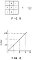
- FIG. 5 is an explanatory view showing in a two-dimensional manner respective tap coefficients of the LPF in the encoder of the first embodiment;
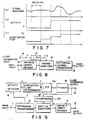
- FIG. 6 is a diagram showing the transform characteristic of the class value C* and the quantization step Sq;
- FIG. 7 is a waveform diagram showing the manner of the adaptive quantization by the system of the first embodiment;
- FIG. 8 is a block diagram showing the outline of the configuration of a decoder in a system according to a first embodiment of this invention;
- FIGS. 9 and 10 are diagrams for explaining an image signal coding/decoding system according to a second embodiment of this invention wherein FIG. 9 is a block diagram showing the outline of the configuration of the encoder and FIG. 10 is a block diagram showing the outline of the configuration of the decoder;
-
- FIG. 4 shows an encoder of an image signal coding/decoding system according to a first embodiment of this invention wherein the same reference numerals are attached to the same components of FIG. 1 showing the conventional encoder, respectively, and the repetitive explanation will be omitted.
- The circuit configuration shown in FIG. 4 differs from that shown in FIG. 1 in that class information which is an output signal from
quantization class determinator 7 is delivered toadaptive quantizer 10 through a low-pass filter (LPF) 9, and that the control operation in theadaptive quantizer 10 is altered. - In FIG. 4, class information which is an output signal from the
quantization class determinator 7 is inputted to LPF 9, at which it is smoothed. The processing at the LPF 9 is the processing in which the processing for pixel values by an ordinary spatial LPF is replaced by the processing for class values every blocks. - FIG. 5 is a diagram representing in a two-dimensional manner respective tap coefficients of the LPF 9. By these tap coefficients, there result raised cosine type frequency characteristics both in a vertical direction and in a horizontal direction.
- Here, the class value C delivered to the LPF 9 expresses four different values, but the class value C* subjected to filtering expresses a greater number of values than that. This class value C* is delivered to
adaptive quantizer 10. - To speak generally, the
adaptive quantizer 10 carries out quantizes the transform coefficient with the step width determined by multiplying the quantization step width Sq determined by the class value C* by the control coefficient k. The coefficient k is the coefficient for controlling quantity of data. This coefficient is determined from the external in order to keep the data quantity outputted from the encoder within the capacity of a transmission system. Accordingly, it can be said that the quantization step width Sq is a relative value for quantization. However, there will now be described the coefficient k as "k=1" in order to simplify the description. - FIG. 6 is a graph showing the transform characteristic of the quantization step width Sq versus the class value C*. In the figure, every time the class value C* is incremented by one, the quantization step width Sq is increased √2 times. Namely, every time the activity value A is increased twice, the quantization step width is increased √2 times.
- FIG. 7(a), (b) and (c) are waveform diagrams showing the manner of the adaptive quantization in the encoder of the first embodiment. FIGS. 7(a) and (b) correspond to FIGS. 3(a) and (b) referred to in the prior art, and represent the signal change before transformation and the activity A, respectively, and FIG. 7(c) represents the quantization step width Sq.
- The image signal waveform shown in FIG. 7(a) indicates a boundary portion between the flat portion and the changing portion in the same manner as in the case of FIG. 3(a). Since the activity A is such that it is small at the flat portion and is large at the changing portion, the activity A becomes large at the block in the vicinity of the boundary as shown in FIG. 7(b).
- In the case of the conventional adaptive quantization, since the filtering processing is not implemented, the quantization step width Sq varies to much extent at the boundary block as shown in FIG. 3(a). On the contrary, in the case of the first embodiment, since filtering processing is implemented, the quantization step Sq gradually increases in the vicinity of the boundary block, and the degree of the change becomes small.
- FIG. 8 shows the outline of the configuration of a decoder in the system according to the first embodiment of this invention. In FIG. 8, compressed data transmitted through the
data output terminal 5 of the encoder of FIG. 4 is delivered to an variable-length decoder 12 through the data input terminal 11. The variable-length decoder 12 converts a variable length code transmitted to a normal code. The code thus obtained is delivered to an inverse-quantizer 13. - On the other hand, an input signal of class information (class C) delivered through the class
information output terminal 8 of the encoder shown in FIG. 4 is delivered to the inverse-quantizer 13 through anLPF 17 having the same characteristics as the LPF 9 shown in FIG. 4. This inverse-quantizer 13 replaces the ordinary code delivered from thedecoder 12 by a representative value of quantization on the basis of the class C* restored by theLPF 17 to deliver the quantization representative value to the orthogonal inverse-transformer 15. - The step width for replacement is determined on the basis of the characteristic of FIG. 6 by the class value C* subjected to filtering in the same manner as in the
adaptive quantizer 10 in the encoder. - The orthogonal inverse-
transformer 15 allows an input signal to be converted by an Inverse Cosine Transform (Inverse-DCT) to reproduce the image signal to output this signal through theimage output terminal 16. - Furthermore, since the quantization classes used in this invention have correlation with adjacent blocks by filtering, even if information of all blocks are not transmitted, substantially the same result as in the case where information of all blocks are transmitted is provided by interpolation. Namely, the reduction of transmitting data is accomplished by thinning quantization class information every several blocks, transmitting them and interpolating class values of blocks which are not transmitted at the result of thinning, from class values of blocks transmitted.
- An image signal coding/decoding system according to a second embodiment of this invention will now be described with reference to FIGS. 9 and 10. FIG. 9 shows the outline of the configuration of an encoder of the system of the second embodiment and FIG. 10 shows the outline of the configuration of a decoder of the system of the second embodiment.
- When attention is first drawn to the encoder of FIG. 9, this encoder mainly differs from the encoder of the first embodiment of FIG. 4 in that the processing in the
LPF 18 is improved, and that an output signal from theLPF 18 is delivered to the classinformation output terminal 8 and an interpolation element (interpolator) 20 through a thinning element (thinner) 19 to deliver an output signal from theinterpolator 20 to theadaptive quantizer 10. Only the difference therebetween will now be described. - The
LPF 18 is of the same structure as that of the LPF 9 of FIG. 4, but a signal including eight kinds (3 bits) of class values C* combined is outputted from theLPF 18. This signals is delivered to the thinner 19. - The thinner 19 thins class values every other block in horizontal and vertical directions to transmit interpolated class values to the decoder side through the class
information output terminal 8, and to deliver it also to theinterpolator 20. - Since the class value is thinned every other block in horizontal and vertical directions, one class value will be transmitted with respect to the "16 x 16" pixels, Accordingly, class values equal to one fourth in the case of the "8 x 8" pixels are transmitted. Thus, a quantity of data transmitted is equal to three eighth of that in the prior art or in the first embodiment.
- The
interpolator 20 prepares, by interpolation, the class value C* of a thinned block by class values of the adjacent blocks. The interpolation is carried out in dependency upon the position of the block. Namely, in the case where the class value C* is present in upper and lower adjacent blocks or left and right blocks, interpolation is performed by adding one half of the class value of one block and one half of the class value of the other block. Further, in the case where the class value C* is present in four adjacent blocks obliquely positioned, interpolation is performed by adding to each other one fourth of the class values of respective four blocks. The coefficient of the interpolation filter in this case is equal to four times greater than that shown in FIG. 5. - In FIG. 10 showing a decoder of the second embodiment, the same reference numerals as those of FIG. 8 are attached to the same components as those of the decoder of the first embodiment, respectively, and the repetitive explanation will be omitted.
- The decoder of the second embodiment is a decoder corresponding to the encoder in the case of thinning a class value of a specified block, shown in FIG. 9. This decoder differs from the decoder of FIG. 8 in that a class value C* inputted through the class
information input terminal 14 is delivered to the inverse-quantizer 13 through aninterpolator 21. - It is of course that the
interpolator 21 performs an interpolating operation similar to that of theinterpolator 20 shown in FIG. 9.
Claims (7)
- An image signal encoder for dividing an input image signal into blocks each having a predetermined number of pixels, for detecting an activity of each block in which activity indicates change in said image signal within said block, for determining a class which directs a quantization step width in accordance with the detection result, and for adaptively quantizing said image signal in accordance with the determination result; said encoder comprising:class determination means for determining a class which directs a quantization step width for each block in accordance with the activity detection results;filter means for low pass filtering said class values; andquantization step determination means for determining a quantization step width for each block on the basis of the filtered values;
wherein said encoder outputs an encoded image signal which is quantized by quantization step widths determined by said quantization step determination means, and outputs supplemental information expressing the condition of said quantization in order that a decoder may perform a corresponding inverse-quantization of the encoded image signal output from the encoder. - The encoder according to claim 1, wherein said supplemental information corresponds to a class value which is obtained by said class determination means.
- The encoder according to claim 1, further comprisingthinner means for thinning block units of said class value after filtering by said filter means; andinterpolation means for interpolating a class value of a thinned block in accordance with an output of said thinner means, thereby outputting an interpolated result to said quantization step determination means;
wherein supplemental information corresponds to said class value of said thinned block which is thinned by block unit and outputted from said thinner means. - A decoder for decoding an encoded signal on the basis of received supplemental information indicating a determined class value and said encoded signal; the supplemental information having been obtained by detecting activity which indicate a change ratio in each block of an image signal which is divided into blocks having predetermined numbers of pixels; determining a class which directs a quantization step width for each block in accordance with the detected activity; and low pass filtering said detected class values said encoded signal being encoded by being quantized by said quantization step width, said decoder comprising:filter means for low pass filtering said supplemental information not only in the block which is object of processing of inverse-quantization but also in peripheral blocks.
- The decoder according to claim 4, whereinsaid supplemental information corresponds to a class value of each block.
- The decoder according to claim 4, whereinsaid supplemental information is a class value corresponding to remaining blocks which are left from thinning, and wherein said decoder further comprises interpolation means for interpolating and restoring a class value corresponding to lost blocks from said class value corresponding to said remaining blocks.
- The encoder according to claim 1,
wherein said supplemental information outputted therefrom, is a signal in which a differential of the informations expressing the condition of said quantization, with respect to successive blocks is coded by a variable-length code.
Applications Claiming Priority (6)
| Application Number | Priority Date | Filing Date | Title |
|---|---|---|---|
| JP26238990 | 1990-09-29 | ||
| JP26238990A JP2536684B2 (en) | 1990-09-29 | 1990-09-29 | Image coding device |
| JP262389/90 | 1990-09-29 | ||
| JP24500891 | 1991-08-30 | ||
| JP24500891A JP2682296B2 (en) | 1991-08-30 | 1991-08-30 | Image coding device |
| JP245008/91 | 1991-08-30 |
Publications (3)
| Publication Number | Publication Date |
|---|---|
| EP0479510A2 EP0479510A2 (en) | 1992-04-08 |
| EP0479510A3 EP0479510A3 (en) | 1994-04-13 |
| EP0479510B1 true EP0479510B1 (en) | 2000-06-28 |
Family
ID=26537007
Family Applications (1)
| Application Number | Title | Priority Date | Filing Date |
|---|---|---|---|
| EP91308896A Expired - Lifetime EP0479510B1 (en) | 1990-09-29 | 1991-09-27 | Image signal coding/decoding system using adaptive quantization |
Country Status (4)
| Country | Link |
|---|---|
| US (1) | US5253075A (en) |
| EP (1) | EP0479510B1 (en) |
| KR (1) | KR960010392B1 (en) |
| DE (1) | DE69132268T2 (en) |
Families Citing this family (41)
| Publication number | Priority date | Publication date | Assignee | Title |
|---|---|---|---|---|
| US5422736A (en) * | 1991-03-22 | 1995-06-06 | Canon Kabushiki Kaisha | Multi-mode image processing permitting selection of quantization process according to image characteristics |
| US6512791B1 (en) * | 1991-05-15 | 2003-01-28 | Canon Kabushiki Kaisha | Image processing apparatus having means for controlling exposure using an orthogonal transformation coefficient |
| US5838834A (en) * | 1991-11-07 | 1998-11-17 | Canon Kabushiki Kaisha | Image processing apparatus and method for quantizing image data and quantization errors using single quantizing unit and pluralities of quantization tables |
| JP3245977B2 (en) * | 1992-06-30 | 2002-01-15 | ソニー株式会社 | Digital image signal transmission equipment |
| US6028961A (en) * | 1992-07-31 | 2000-02-22 | Canon Kabushiki Kaisha | Image processing method and apparatus |
| EP0586074B1 (en) * | 1992-07-31 | 2001-11-14 | Canon Kabushiki Kaisha | Image processing apparatus and method suitable for multistage compression |
| JP3196906B2 (en) * | 1992-08-21 | 2001-08-06 | 富士ゼロックス株式会社 | Image signal encoding device |
| US5379122A (en) * | 1992-10-02 | 1995-01-03 | Xerox Corporation | Decompression of standard ADCT-compressed images |
| US5861921A (en) * | 1993-03-29 | 1999-01-19 | Canon Kabushiki Kaisha | Controlling quantization parameters based on code amount |
| CN1092446C (en) * | 1993-05-31 | 2002-10-09 | 佳能株式会社 | Image processing method and apparatus |
| JP3360695B2 (en) * | 1993-06-17 | 2002-12-24 | ソニー株式会社 | Image data quantization circuit |
| KR0127329B1 (en) * | 1993-08-14 | 1997-12-29 | 구자홍 | Buffer control apparatus for intraframe using tct |
| DE69421795T2 (en) * | 1993-08-30 | 2000-06-29 | Sony Corp | DEVICE AND METHOD FOR CODING IMAGES |
| JP3569963B2 (en) * | 1993-09-08 | 2004-09-29 | ソニー株式会社 | Image compression device |
| US6674897B1 (en) | 1993-09-08 | 2004-01-06 | Sony Corporation | Picture data compression device and red data detection device |
| JP2914549B2 (en) * | 1993-09-17 | 1999-07-05 | 富士ゼロックス株式会社 | Image coding method |
| KR0183688B1 (en) * | 1994-01-12 | 1999-05-01 | 김광호 | Image encoding method and device |
| US5719961A (en) * | 1994-07-22 | 1998-02-17 | Apple Computer, Inc. | Adaptive technique for encoder and decoder signal transformation |
| JPH08116448A (en) * | 1994-10-13 | 1996-05-07 | Fuji Xerox Co Ltd | Coder and decoder for image signal |
| JP3634410B2 (en) * | 1994-10-18 | 2005-03-30 | キヤノン株式会社 | Image processing system, image processing apparatus and method |
| JP2900983B2 (en) * | 1994-12-20 | 1999-06-02 | 日本ビクター株式会社 | Moving image band limiting method |
| JP3258840B2 (en) * | 1994-12-27 | 2002-02-18 | シャープ株式会社 | Video encoding device and region extraction device |
| US5870434A (en) * | 1994-12-29 | 1999-02-09 | Sony Corporation | Apparatus and method for quantizing a digital signal based on quantizing steps including odd-numbered steps |
| JPH08214309A (en) * | 1995-02-07 | 1996-08-20 | Canon Inc | Image signal encoder |
| JPH0951504A (en) * | 1995-08-03 | 1997-02-18 | Matsushita Electric Ind Co Ltd | Image encoding device and image decoding device |
| GB2342525B (en) | 1995-10-30 | 2000-06-28 | Sony Uk Ltd | Image quantisation based on image activity |
| US6204889B1 (en) * | 1995-12-15 | 2001-03-20 | Canon Kabushiki Kaisha | Image information processing apparatus |
| JP3116994B2 (en) * | 1996-08-29 | 2000-12-11 | 富士ゼロックス株式会社 | Image quality prediction apparatus and method and image quality control apparatus and method |
| FR2753330B1 (en) * | 1996-09-06 | 1998-11-27 | Thomson Multimedia Sa | QUANTIFICATION METHOD FOR VIDEO CODING |
| EP0841820A3 (en) * | 1996-11-08 | 2005-11-09 | Matsushita Electric Industrial Co., Ltd. | Method and apparatus for encoding, multiplexing and transmitting a video signal |
| US20030012445A1 (en) * | 1997-05-08 | 2003-01-16 | Nekka Matsuura | Image processing system for compressing image data including binary image data and continuous tone image data by a sub-band transform method with a high-compression rate |
| KR100240770B1 (en) * | 1997-07-11 | 2000-01-15 | 이형도 | Scalable coding apparatus and method for improving function of energy compensation/inverse-compensation |
| KR100269125B1 (en) * | 1997-10-25 | 2000-10-16 | 윤덕용 | Image post processing method and apparatus for reducing quantization effect |
| US7822117B1 (en) * | 2005-09-30 | 2010-10-26 | Ambarella, Inc. | Video encoder rate control using bit usage measuring and allocating by macroblock classes |
| GB2438006A (en) * | 2006-05-09 | 2007-11-14 | Tandberg Television Asa | Adaptive quantisation for border processing |
| CN101523441B (en) * | 2006-09-29 | 2012-01-18 | 汤姆逊许可证公司 | Spatial activity metric and method for evaluating the same |
| US20080285645A1 (en) * | 2007-05-17 | 2008-11-20 | Tandberg Television Asa | Adaptive border processing |
| US10630991B2 (en) | 2015-12-15 | 2020-04-21 | Nippon Telegraph And Telephone Corporation | Image difference detection device, method for detecting image difference, and computer program |
| CN109996076B (en) * | 2016-10-12 | 2021-08-06 | 深圳市大疆创新科技有限公司 | Code rate control method, computer system and device |
| US10491897B2 (en) * | 2018-04-13 | 2019-11-26 | Google Llc | Spatially adaptive quantization-aware deblocking filter |
| GB2578633B (en) * | 2018-11-02 | 2021-10-13 | Advanced Risc Mach Ltd | Encoding data arrays |
Family Cites Families (5)
| Publication number | Priority date | Publication date | Assignee | Title |
|---|---|---|---|---|
| JPS60153264A (en) * | 1984-01-20 | 1985-08-12 | Ricoh Co Ltd | Transmission system of half tone picture |
| CA1318969C (en) * | 1987-06-25 | 1993-06-08 | Shoji Mizuno | Encoding of a picture signal in consideration of contrast in each picture and decoding corresponding to the encoding |
| US5093872A (en) * | 1987-11-09 | 1992-03-03 | Interand Corporation | Electronic image compression method and apparatus using interlocking digitate geometric sub-areas to improve the quality of reconstructed images |
| US5051840A (en) * | 1988-12-14 | 1991-09-24 | Fuji Photo Film Co., Ltd. | Device for coding a picture signal by compression |
| US5060285A (en) * | 1989-05-19 | 1991-10-22 | Gte Laboratories Incorporated | Hierarchical variable block size address-vector quantization using inter-block correlation |
-
1991
- 1991-09-27 KR KR1019910016857A patent/KR960010392B1/en not_active IP Right Cessation
- 1991-09-27 EP EP91308896A patent/EP0479510B1/en not_active Expired - Lifetime
- 1991-09-27 DE DE69132268T patent/DE69132268T2/en not_active Expired - Lifetime
- 1991-09-30 US US07/766,950 patent/US5253075A/en not_active Expired - Lifetime
Also Published As
| Publication number | Publication date |
|---|---|
| EP0479510A2 (en) | 1992-04-08 |
| DE69132268T2 (en) | 2000-10-26 |
| KR920007365A (en) | 1992-04-28 |
| KR960010392B1 (en) | 1996-07-31 |
| US5253075A (en) | 1993-10-12 |
| DE69132268D1 (en) | 2000-08-03 |
| EP0479510A3 (en) | 1994-04-13 |
Similar Documents
| Publication | Publication Date | Title |
|---|---|---|
| EP0479510B1 (en) | Image signal coding/decoding system using adaptive quantization | |
| US5937101A (en) | Post-processing device for eliminating blocking artifact and method therefor | |
| US6226050B1 (en) | Signal adaptive filtering method for reducing ringing noise and signal adaptive filter | |
| EP0586225B1 (en) | Orthogonal transform coding apparatus and decoding apparatus | |
| EP0789494B1 (en) | Coding apparatus | |
| US5367385A (en) | Method and apparatus for processing block coded image data to reduce boundary artifacts between adjacent image blocks | |
| EP0831660B1 (en) | Video coder with prediction of the transform coefficients | |
| US8165222B2 (en) | Video coder employing pixel transposition | |
| US6650786B2 (en) | Image encoding apparatus and image decoding apparatus | |
| AU693726B2 (en) | Video coding and decoding system and method | |
| EP0838954A2 (en) | Image encoding and decoding apparatus | |
| US5283656A (en) | Data compression apparatus for video signal and method of data compression for video signal | |
| WO1997049250A1 (en) | Device and method for encoding picture and device and method for decoding picture | |
| JPH05219385A (en) | Picture compression expansion method and device | |
| JPH04321391A (en) | Picture coder and decoder | |
| US6320987B1 (en) | Pre-DCT residue filter | |
| JPH10229559A (en) | Method and filter for reducing effect due to block processing | |
| JP2682296B2 (en) | Image coding device | |
| JP2901656B2 (en) | Image coding device | |
| JP3497664B2 (en) | Stereoscopic image coding device | |
| JP3211989B2 (en) | Orthogonal transform encoding device and decoding device | |
| JP3617253B2 (en) | Image coding apparatus and method | |
| JPH11298898A (en) | Block distortion reduction circuit | |
| JP3448883B2 (en) | Adaptive quantizer | |
| KR0178711B1 (en) | Encoding and decoding system using adaptive post-processing |
Legal Events
| Date | Code | Title | Description |
|---|---|---|---|
| PUAI | Public reference made under article 153(3) epc to a published international application that has entered the european phase |
Free format text: ORIGINAL CODE: 0009012 |
|
| 17P | Request for examination filed |
Effective date: 19911113 |
|
| AK | Designated contracting states |
Kind code of ref document: A2 Designated state(s): DE FR GB |
|
| PUAL | Search report despatched |
Free format text: ORIGINAL CODE: 0009013 |
|
| AK | Designated contracting states |
Kind code of ref document: A3 Designated state(s): DE FR GB |
|
| 17Q | First examination report despatched |
Effective date: 19970716 |
|
| GRAG | Despatch of communication of intention to grant |
Free format text: ORIGINAL CODE: EPIDOS AGRA |
|
| RIC1 | Information provided on ipc code assigned before grant |
Free format text: 6H 04N 7/30 A |
|
| RIC1 | Information provided on ipc code assigned before grant |
Free format text: 6H 04N 7/30 A |
|
| GRAG | Despatch of communication of intention to grant |
Free format text: ORIGINAL CODE: EPIDOS AGRA |
|
| GRAH | Despatch of communication of intention to grant a patent |
Free format text: ORIGINAL CODE: EPIDOS IGRA |
|
| GRAH | Despatch of communication of intention to grant a patent |
Free format text: ORIGINAL CODE: EPIDOS IGRA |
|
| GRAA | (expected) grant |
Free format text: ORIGINAL CODE: 0009210 |
|
| AK | Designated contracting states |
Kind code of ref document: B1 Designated state(s): DE FR GB |
|
| REF | Corresponds to: |
Ref document number: 69132268 Country of ref document: DE Date of ref document: 20000803 |
|
| ET | Fr: translation filed | ||
| PLBE | No opposition filed within time limit |
Free format text: ORIGINAL CODE: 0009261 |
|
| STAA | Information on the status of an ep patent application or granted ep patent |
Free format text: STATUS: NO OPPOSITION FILED WITHIN TIME LIMIT |
|
| 26N | No opposition filed | ||
| REG | Reference to a national code |
Ref country code: GB Ref legal event code: IF02 |
|
| PGFP | Annual fee paid to national office [announced via postgrant information from national office to epo] |
Ref country code: FR Payment date: 20100921 Year of fee payment: 20 |
|
| PGFP | Annual fee paid to national office [announced via postgrant information from national office to epo] |
Ref country code: GB Payment date: 20100922 Year of fee payment: 20 |
|
| PGFP | Annual fee paid to national office [announced via postgrant information from national office to epo] |
Ref country code: DE Payment date: 20100922 Year of fee payment: 20 |
|
| REG | Reference to a national code |
Ref country code: DE Ref legal event code: R071 Ref document number: 69132268 Country of ref document: DE |
|
| REG | Reference to a national code |
Ref country code: DE Ref legal event code: R071 Ref document number: 69132268 Country of ref document: DE |
|
| REG | Reference to a national code |
Ref country code: GB Ref legal event code: PE20 Expiry date: 20110926 |
|
| PG25 | Lapsed in a contracting state [announced via postgrant information from national office to epo] |
Ref country code: GB Free format text: LAPSE BECAUSE OF EXPIRATION OF PROTECTION Effective date: 20110926 |
|
| PG25 | Lapsed in a contracting state [announced via postgrant information from national office to epo] |
Ref country code: DE Free format text: LAPSE BECAUSE OF EXPIRATION OF PROTECTION Effective date: 20110928 |