EP0475975B1 - Computer-aided engine diagnostic system - Google Patents
Computer-aided engine diagnostic system Download PDFInfo
- Publication number
- EP0475975B1 EP0475975B1 EP90908426A EP90908426A EP0475975B1 EP 0475975 B1 EP0475975 B1 EP 0475975B1 EP 90908426 A EP90908426 A EP 90908426A EP 90908426 A EP90908426 A EP 90908426A EP 0475975 B1 EP0475975 B1 EP 0475975B1
- Authority
- EP
- European Patent Office
- Prior art keywords
- computer
- input
- computer means
- measurement
- connector
- Prior art date
- Legal status (The legal status is an assumption and is not a legal conclusion. Google has not performed a legal analysis and makes no representation as to the accuracy of the status listed.)
- Expired - Lifetime
Links
Images


Classifications
-
- F—MECHANICAL ENGINEERING; LIGHTING; HEATING; WEAPONS; BLASTING
- F02—COMBUSTION ENGINES; HOT-GAS OR COMBUSTION-PRODUCT ENGINE PLANTS
- F02B—INTERNAL-COMBUSTION PISTON ENGINES; COMBUSTION ENGINES IN GENERAL
- F02B77/00—Component parts, details or accessories, not otherwise provided for
- F02B77/08—Safety, indicating or supervising devices
-
- G—PHYSICS
- G01—MEASURING; TESTING
- G01R—MEASURING ELECTRIC VARIABLES; MEASURING MAGNETIC VARIABLES
- G01R31/00—Arrangements for testing electric properties; Arrangements for locating electric faults; Arrangements for electrical testing characterised by what is being tested not provided for elsewhere
- G01R31/005—Testing of electric installations on transport means
- G01R31/006—Testing of electric installations on transport means on road vehicles, e.g. automobiles or trucks
- G01R31/007—Testing of electric installations on transport means on road vehicles, e.g. automobiles or trucks using microprocessors or computers
Definitions
- THIS INVENTION relates to a computerised diagnostic system for internal combustion engines.
- the invention is directed to a method of, an apparatus for, computer-aided diagnosis of electronically fuel injected (EFI) internal combustion engines.
- EFI electronically fuel injected
- EFI engines in automobiles are commonly controlled by an on-board computer, typically a microprocessor-based device, which controls the timing and duration of the fuel injection in response to operational parameters sensed by a number of sensors on the engine, e.g. temperature, engine speed, throttle position, air flow, etc. These operational parameters can be measured many times per second so that the engine is continually operated at optimum efficiency.
- an on-board computer typically a microprocessor-based device, which controls the timing and duration of the fuel injection in response to operational parameters sensed by a number of sensors on the engine, e.g. temperature, engine speed, throttle position, air flow, etc.
- microprocessor or micro-computer based control circuits for EFI engines are programmed to accept measured values of sensed operational parameters only when such values fall within a predetermined range e.g. to avoid responding to spurious signals or to avoid acting on faulty measurements. If the value of an operational parameter as measured by a particular sensor is outside the predetermined range, the sensor may be judged by the computer control system to have failed (whether this is, in fact, correct or not), and the actual output signal of the sensor may be replaced by a standard value (as described, for example, in United States patent no. 4,780,826). The use of a default value enables the engine to keep operating despite the failure of a sensor. However, although the engine will still operate, it will not perform as efficiently as it should. Since the fault in the engine may be masked by the default value inserted by the computerised electronic control system, it is difficult, if not impossible, for mechanics to locate and correct the fault using conventional tools.
- U.S. patent 4,267,569 describes a control system for a vehicle that includes self diagnostic capability.
- the diagnostic program can be initiated externally, on the basis of time or distance travelled, or according to a preset schedule generated by the diagnostic program itself.
- the outputs of various sensors on the vehicle are fed (through appropriate interfaces) to an on-bord electronic control module (ECM) where the sensor data is processed and stored. Thereafter, upon command, the data can be read out, as serial digital data, by the diagnostic program.
- ECM electronice control module
- the present invention provides apparatus for diagnosing an internal combustion engine having a plurality of sensors connected to an on-board microcomputer via a multiwire connector, the apparatus comprising: independent external computer means having a display; input means having a multiple input connector suitable for connection to the multiwire connector; and an interface circuit connected between the computer means and the input means, the interface circuit comprising a multimode measuring means responsive to the computer means to switch to a selected one of a plurality of measurement modes, said modes including a mode measuring voltage, a mode measuring current or resistance and a mode measuring pulse rate and producing a single analog output, a switching circuit (1", 2", 3", 4") responsive to the computer means to selectively connect the measurement means to a selected input of the multiple input connector, the output of the measurement means being connected to an analog-to-digital converter for converting to digital form the value, as measured by the measurement means, of an operational parameter sensed by a sensor corresponding to the selected input, and output means for outputting the digitised measured value directly to the computer means; wherein in use, the computer means is
- the computer means is preferably programmed to provide tutorial or similar information to assist the operator in locating and rectifying the possible fault. This procedure is repeated sequentially for all selected operational parameters.
- the engine is an EFI engine and the operational parameters to be tested include battery voltage, ignition pulse, starter signal, throttle position sensor, air temperature sensor, air flow meter, coolant temperature sensor, fuel injectors.
- the computer means need not be a dedicated or custom-built computer (although it can be), but may suitably be any one of a number of commonly available computers such as a standard laptop computer, or a personal computer, and no substantial circuit modification of such a computer is required. Thus, the cost can be minimised. Further, the computer can be used for other applications when not required for EFI diagnosing.
- the input means may be in the form of a multipin socket which is connectable to the plug connected to the engine sensors. (This plug is normally connected to the on-board microcomputer found on modern vehicles having microcomputer-controlled EFI engines.) In this embodiment, the sensors are able to be examined rapidly and automatically for fault location.
- the input means may also include a probe which is placed in electrical contact with a selected sensor under test or other operational parameter, in accordance with instructions displayed on the computer display.
- the input means is in the form of a multipin plug connected between the engine sensors and on-board microcomputer, end selectively switched under computer control. This enables rapid testing of not only the sensors, but also the on-board microcomputer.
- an interface device is provided to interpret switching control data from the computer means and to convert the measured values of selected operational parameters into computer readable format.
- the interface device includes a multimode measurement device, analogous to a multimeter, which is controlled by the computer means to switch to the appropriate measurement mode for the selected operational parameter, e.g. voltmeter, ohmmeter, tachometer.
- the measured value is converted to digital form and output by the interface device to the computer means, typically in serial data format.
- the diagnostic comparison of the measured value with the predetermined range is then performed by the computer software and the results are displayed to the user, together with repair or troubleshooting instructions if necessary.
- a method of diagnosing an internal combustion engine using the above described apparatus comprising the steps of sequentially measuring selected operational parameters of said engine, providing the measured values to the computer means, comparing the measured values with respective predetermined ranges stored in the computer means, displaying the results of such comparisons on the computer display, and displaying tutorial instructions for repair or troubleshooting in the event that measured values do not fall within their respective predetermined ranges.
- the diagnostic apparatus comprises computer means 10 which may suitably be a conventional portable or laptop computer. Alternatively, a standard personal computer (PC) may be used. Such computers are commonly available and are within the financial reach of most motor repair garages.
- the computer means is a conventional portable computer 10 which is preferably housed in a robust casing designed to withstand the harsh environment of an engine workshop.
- An interface device 20 is interposed between the engine 30 under test and the portable computer 10 to interpret switching control data from the computer means and to convert the measured values of operational parameters of the engine 30 into suitable digital form for input to, and processing by, the portable computer 10.
- the interface device 20 can be connected to the engine 30 by means of one or more probes 25.
- the probes 25 typically, two probes are used, one probe being earthed, and the other probe 25 being placed manually at sensors at various locations on the engine 30 under test according to programmed instructions provided by the portable computer 10 on its associated display.
- the input of the interface device 20 is connected to the multipin plug which normally connects the engine sensors to the on-board microprocessor controlling the operation of the EFI engine.
- the input of the interface device 20 is switched automatically between the various sensors connected to the multipin plug, the switching being controlled by the portable computer 10.
- the operator need only remove the multipin plug from the microprocessor controller on board the vehicle and connect it, via a suitable connector lead or adaptor, to the interface device 20.
- the operational parameters measured by the individual sensors are then scanned sequentially and the measured data is fed via the interface 20 to the portable computer 10 for processing.
- Operational parameters are measured in real time.
- the diagnostic software in the portable computer 10 is designed to compare the measured value of an operational parameter with a predetermined range. This range may be derived from manufacturer's specifications or by empirical determination. If the measured operational parameter is within the predetermined range, the diagnostic program will then proceed onto the next operational parameter. However, if the measured parameter is outside the allowable range, the program will then switch to tutorial mode to instruct the operator the required steps to locate and rectify the fault.
- the input of the interface device 20 is interposed between the multipin plug and the on-board microprocessor so that not only can sensor information be received by the diagnostic computer but also test valves can be fed to the on-board microprocessor to check the proper operation thereof.
- the interface device 15 is basically a computer controlled multimeter which can operate as a voltmeter, ohmmeter or tachometer, together with an analog-to-digital converter 22 for converting measured valves to digital form.
- the interface circuit can be constructed at low cost and is suitable for small motor repair workshops.
- control data is fed from the portable computer 10 to the interface circuit 15 along "data in" line 21 in serial form.
- This control information is used to provide the required voltages at control outputs 1, 2, 3, 4 to actuate a switch, or combination of switches, 1', 2', 3', 4' to allow the interface 15 to operate in one of its voltmeter, ohmmeter or tachometer modes.
- the switches are shown in the form of solenoid relays. However, it will be appreciated by those skilled in the art that other suitable switching devices can be used, e.g. solid state switches.
- the portable computer 10 will instruct the operator to connect the probe 25 to the positive battery terminal, the other probe (not shown) being earthed.
- the computer 10 will then transmit the required control data to the interface 15 via line 21 so that switch 1' will be closed, and the remaining switches 2', 3', 4' will be opened by control outputs 1, 2, 3, 4 respectively.
- the voltage sensed by probe 25 will be fed directly to the analog-to-digital (A/D) converter 22 within the interface.
- the interface device 15 suitably comprises appropriate ranging and shaping circuits (not shown) to place the measured voltage in a suitable condition for A/D conversion).
- the measured voltage is then converted to digital form and fed, in serial data format, to the computer 10 via line 23.
- the value of the battery voltage will then be compared with a predetermined range previously input to the computer.
- the computer proceeds to the next test. For example, it may then display instructions to the operator to start the engine, with the probe 25 being left connected to the positive terminal of the battery. During this procedure, the battery starting and charging voltages will be measured and input to the computer 10 which compares them with predetermined ranges.
- the interface device 15 is switched to ohmmeter mode.
- the control information fed by computer 10 along line 21 will cause the control outputs to close switches 1' and 4', and open all other switches.
- a reference voltage (Vref) is applied to a reference resistance 24 in order to derive a known current. This current is fed via switch 4' and probe 25 to the resistance being measured.
- the resulting voltage which is proportional to the measured resistance, is input to the A/D converter 22 wherein it is converted to serial digital form and fed to computer 10 via output line 23.
- the reference voltage may be derived from a battery or reference voltage circuit within the interface device 15, or from an external source.
- the interface device 15 is switched to tachometer mode. In this mode, switches 2' and 3' are closed, and all other switches are open.
- the probe 25 is placed on a source of periodic pulses dependant on engine speed (e.g. by connecting to a spark plug, ignition coil or speed sensor).
- the periodic pulses sensed by probe 25 are fed to a pulse tachometer circuit 26 which provides an output voltage proportional to the frequency of the incoming pulses.
- the output voltage is fed via switch 2' to the input of the A/D converter 22 where it is again converted to serial digital form and fed to the computer 10.
- the switching of the interface device 15 between its various voltmeter, ohmmeter and tachometer modes is performed automatically under computer control, and the transmission of control and measurement data between the interface 15 and computer 10 is governed by a suitable clock or timing mechanism.
- the operator need only shift the probe 25 as instructed by the programmed instructions displayed on the screen of the computer 10. No special training or expertise is required, and the required tutorial information is able to be displayed on the screen of computer 10.
- the allowable range of selected operational parameters for various models of vehicles, together with diagnostic subroutines and tutorial information, can be stored on individual floppy discs, and purchased as and when required. This information can then be loaded into the computer before testing.
- the probe is shifted manually from location to location to measure the required operational parameters sequentially.
- the interface circuit is of low cost design, the need to continually shift the probe 25 renders the diagnostic procedure somewhat lengthy.
- an automatic version of the interface circuit is used in a preferred embodiment of the invention and is illustrated schematically in Fig. 3.
- the automatic interface 35 of Fig. 3 is adapted to receive control data in serial form from portable computer 10 along line 31.
- the serial control data is converted to parallel form by a serial-to-parallel converter in circuit 32 within the interface 35. More specifically, the incoming serial data is converted into eight bit parallel form.
- the first six bits are fed via lines 33 to an A/D converter 34, and are used to select one of a possible 64 input lines to the A/D converter 34.
- the seventh and eighth bits are used to control the switching of four switches 1", 2", 3", 4" to select the appropriate mode a multimeter circuit 36, in a similar manner to that described above with reference to Fig. 2.
- the circuit 36 will measure the input as a voltmeter, ohmmeter or tachometer as the case may be.
- the input lines are connected to a multipin socket 29.
- the multipin plug connected to the various sensors on the engine is disconnected from the on-board microprocessor, and reconnected to the multipin socket 29.
- Control data output from the computer is used to select an appropriate incoming sensor line, i.e. the desired operational parameter, and to switch the multimeter device 36 to the appropriate measurement mode for the selected operational parameter.
- the measured value on the selected line is converted into digital form by A/D converter 34, and fed (in parallel format) along lines 37 to a parallel-to-serial converter within circuit 32.
- the output serial data is then fed to computer 10 along output line 38.
- the switching of the A/D converter 34 and S/P, P/S converters 32 is also controlled by a clock 39.
- the computer 10 can rapidly measure the operational parameters of the engine under test since no manual relocation of the probe is necessary.
- the measured values of the operational parameters can be processed immediately and/or stored for subsequent analysis.
- the computer can automatically compare all measured operational parameters with their respective allowable ranges, and provide a summary and fault analysis at the end of the diagnostic routine.
- the computer may measure each operational parameter individually and display the results of the diagnostic comparisons on the screen sequentially.
- a Select Menu a particular sensor or operational parameter can be checked.
- the automatic interface 35 is simple to use since the operator need only connect it to the on-board plug. Suitable adaptor sockets can be provided to suit the various models of plugs found on on-board microprocessors.
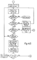
- FIG. 4 A flow chart of an example of suitable software for the computer 10 is shown in Fig. 4.
- the software is both diagnostic and tutorial in nature. In other words, it not only locates the fault, but provides repair instructions and trouble shooting advice.
- each operational parameter or device is tested sequentially.
- the battery voltage is first checked. If the battery voltage is not within the prescribed range, instructions are provided for repairing the battery or the charging system of the vehicle. The earthing, ignition, starter, throttle sensor, air temperature sensor, air flow meter, coolant temperature sensor, the injectors, relay and power supply are then tested sequentially.
- tutorial information is provided on the screen of the computer to assist the operator in understanding the test being conducted.
- the operational parameter of the particular device under test is measured and compared with a predetermined range which has previously been entered into the computer memory. If the measured parameter is within the prescribed range, the program proceeds to the next test. If not, repair or trouble shooting instructions are provided on the screen for the operator.
- the operator is able to ascertain whether the particular sensor measuring that operational parameter is operating correctly. For example, if the reading obtained from a particular sensor is outside the prescribed range, the operational parameter can be measured directly to ascertain whether it is, in fact, incorrect or whether the sensor is faulty.
- the diagnostic equipment of the present invention can also be used to ascertain whether the on-board microprocessor is faulty.
- the diagnostic apparatus of the present invention can be used to test itself, i.e. to test whether the interface circuit is operating correctly.
- Figs. 5 to 7 iilustrate a further preferred embodiment of the invention in which the input of the interface circuit is connected between the on-board microprocessor and the engine sensors.
- the interface circuit 40 of this embodiment is connected to a portable or personal computer ("PC") 41 via a coupling circuit and receiver/line interface 42, a circuit diagram of which is shown in Fig. 6.
- Circuit 42 provides optical isolation between the PC and the interface 40, and converts the signals to RS485 levels.
- the power for the RS485 signals is received from the interface circuit 40 via the data cable.
- the RS485 interface preferably has terminating resistors and a filtering network on each input line.
- the interface 40 is connected, via coupling circuit 42, to a parallel input/output port of the PC, for example a printer port.
- a parallel input/output port of the PC for example a printer port.
- the following signal lines of the parallel I/O port of the PC are used:
- the signals fed from the coupling circuit 42 to the interface 40 include ADDRESS/DATA, DATA CLOCK and ADDRESS CLOCK, while the signals received from the interface 40 include RETURN DATA.
- interface 40 is connected between the plug or harness connector to which the engine sensors are connected, and the on-board microcomputer.
- a T-connector 43 is used to plug into the harness connector and the socket connected to the on-board computer.
- the T-connector 43 is typically provided in a variety of sizes and configurations to suit different models of automobile engine controllers.
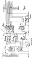
- the interface circuit 40 is shown in more detail in Fig. 7.
- the circuit has forty-eight line control circuits 50 for switching between the connections to the engine sensors and the on-board microcomputer.
- the forty-eight line control circuits 50 are housed on six boards of eight circuits each.
- To connect the interface 40 to a particular one of the 48 lines, the computer sends the appropriate address data to interface 40 via coupling circuit 42.
- the address data is clocked and decoded and switched to the appropriate address lines by addressing circuit 51.
- Address lines EH1, EH2, EH3 are used to select the particular one of the six cards to which the line is connected, while address lines A, B, C are used to select the desired one of the eight lines connected to that card.
- the line control circuits 50 each include two relays connected in series between the sensor harness connectcr 45 and the on-board computer connector 46 for each of the forty-eight lines.
- a connection (MUX) is also made to each line via a 100 K ohm resistor.
- both relays in the selected line are "OFF"
- there is a direct connection between the sensor of that line and the on-board computer i.e. a normal connection.
- Voltage and pulse measurements can be taken on the line in this mode, the measurements being output on the MUX OUT line.
- the output voltage is fed to a first input of a two-input multiplexer 52, the output of which is connected to a 12 bit analog-to-digital converter (ADC) 53.
- ADC analog-to-digital converter
- the digitized voltage reading is fed into a 12 bit shift register 54 from which it is transmitted to the RETURN DATA line to the coupling circuit 42 and hence the PC 41.
- the counter/time circuit used in the illustrated embodiment is a triple counter/timer comprising: a first timer set up as a rate generator dividing a 1 MHz signal down to 10 KHz; a second timer set up as a hardware triggered monostable using the 10 KHz as a reference, to produce a one second output pulse; and a third timer set up as an event counter, gated, for one second, by the first timer and counting the valid pulses received. The pulse frequency is then provided by the number of pulses received in the one second interval.
- the interface circuit 40 can also be used to measure pulse length.
- valid pulses are fed to the signal processing circuit 55 where the triple counter/timer is set up such that the first timer serves as a rate generator dividing 1 MHz down to 100 KHz, the second timer is not used, and the third timer is set up as a pulse counter, preloaded with a maximum count.
- the 100 KHz pulses from the first timer decrement the count in the third timer, until the falling edge of the pulse is detected. (No further pulses are allowed through to the counter when the next rising edge is received unless the pulse length measuring circuit has been reset).
- the final count in the third counter is deducted from the maximum count originally entered into the counter to obtain the length of the pulse in increments of 0.01 milliseconds.
- the third timer is again preloaded with its maximum count.
- the pulse frequency and/or pulse width measurements are transferred to DATA TX shift register 56 for transmittal to the PC 41 via the RETURN DATA line.
- Open circuit voltage and pulse measurements can be taken by leaving the first relay (left hand relay as depicted in Fig. 7) OFF, i.e. maintaining the connection to the on-board computer, while switching ON the second relay (the right hand relay as depicted in Fig. 7) to break the connection between the sensor line and the on-board computer.
- the relay states are reversed. That is, the second relay is switched OFF to maintain the connection to the sensor line, while the first relay is switched ON to break the connection to the on-board computer and connect the sensor line to the COMMON LINE. Resistance measurements between the sensor line and ground are taken in this mode.
- a 2.5 volt reference voltage is switched, via switch 57, through a selected one of two known resistances to the COMMON LINE (which has been switched to the sensor line).
- the known resistance is switchable between 25 K ohm and 250 ohm.
- the voltage on the COMMON line is fed to the second input of two-input multiplexer 52 and converted to 12 bit digital format by ADC 53.
- the digitized value is fed to shift register 54 for transmission to the PC 41 via the RETURN DATA line.
- the interface 40 also has connections for four manual probes 60 which can be placed at desired locations on the engine under test. Either 12 volts or ground can be selectively switched to the probes under computer control by the interface 40. As shown in Fig. 7, the probe connections 60 are each connected to addressing circuit 51 via a respective pair of relays 61, 62. If the relay 61 of a particular probe is operated, that probe is connected to the 12 volt battery voltage of the vehicle. On the other hand, if the relay 62 of a probe is operated, the respective probe is connected to the vehicle ground. All probe connections to the addressing circuit 51 are protected by five Amp thermal circuit breakers 63.
- the interface circuit 40 enables the computer to address a particular sensor line and take measurements of voltage, pulse width and/or frequency and resistance on that line simply by switching of the appropriate relays. Selected voltages can also be switched to the manual probes under computer control. Thus, under control of appropriate software on PC 41, the interface circuit 40 is able to automatically access all sensor lines and take the appropriate readings, which are then relayed back to the PC for diagnostic assessment.
- the sensor lines can be isolated, and specified values can be fed to the on-board microcomputer with resultant monitoring of the microcomputer output as evidenced by the engine performance.
- the diagnostic system of the abovedescribed embodiment is able to not only locate faults in the engine sensors, but also in the operation of the on-board computer.
Landscapes
- Engineering & Computer Science (AREA)
- Chemical & Material Sciences (AREA)
- Combustion & Propulsion (AREA)
- Mechanical Engineering (AREA)
- General Engineering & Computer Science (AREA)
- Computer Hardware Design (AREA)
- Microelectronics & Electronic Packaging (AREA)
- Physics & Mathematics (AREA)
- General Physics & Mathematics (AREA)
- Combined Controls Of Internal Combustion Engines (AREA)
- Testing Of Engines (AREA)
Abstract
Description
- THIS INVENTION relates to a computerised diagnostic system for internal combustion engines. In particular, the invention is directed to a method of, an apparatus for, computer-aided diagnosis of electronically fuel injected (EFI) internal combustion engines.
- EFI engines in automobiles are commonly controlled by an on-board computer, typically a microprocessor-based device, which controls the timing and duration of the fuel injection in response to operational parameters sensed by a number of sensors on the engine, e.g. temperature, engine speed, throttle position, air flow, etc. These operational parameters can be measured many times per second so that the engine is continually operated at optimum efficiency.
- Many microprocessor or micro-computer based control circuits for EFI engines are programmed to accept measured values of sensed operational parameters only when such values fall within a predetermined range e.g. to avoid responding to spurious signals or to avoid acting on faulty measurements. If the value of an operational parameter as measured by a particular sensor is outside the predetermined range, the sensor may be judged by the computer control system to have failed (whether this is, in fact, correct or not), and the actual output signal of the sensor may be replaced by a standard value (as described, for example, in United States patent no. 4,780,826). The use of a default value enables the engine to keep operating despite the failure of a sensor. However, although the engine will still operate, it will not perform as efficiently as it should. Since the fault in the engine may be masked by the default value inserted by the computerised electronic control system, it is difficult, if not impossible, for mechanics to locate and correct the fault using conventional tools.
- Complex and expensive diagnostic equipment is normally required to locate the fault. Such equipment is often computer-based, requiring a computer device manufactured specifically for that particular application. The use of such complex and specialised diagnostic equipment and the need for trained technicians result in increased costs for motor vehicle repair.
- U.S. patent 4,267,569 describes a control system for a vehicle that includes self diagnostic capability. The diagnostic program can be initiated externally, on the basis of time or distance travelled, or according to a preset schedule generated by the diagnostic program itself. The outputs of various sensors on the vehicle are fed (through appropriate interfaces) to an on-bord electronic control module (ECM) where the sensor data is processed and stored. Thereafter, upon command, the data can be read out, as serial digital data, by the diagnostic program. However, this know diagnostic system has several inherent disadvantages.
- First, if a fault exists in the ECM itself, the fault cannot always be detected as there is no guarantee that a faulty ECM can correctly diagnose its own faults. Secondly, due to the interposition of the ECM between the sensors and the diagnostic equipment, ground faults (a common error in vehicle sensorss) may not be detected. Thirdly, the diagnostic equipment is not truly independent, but is dependent on the ECM for its proper operation.
- It is the object of the present invention to provide apparatus for computer-aided diagnosis of EFI engines which is within the economic and technical reach of most motor mechanics.
- It is a further object of the invention to provide a method of computer-aided diagnosis of EFI engines wherein a diagnostic computer program includes tutorial information to enable such diagnosis to be performed by most motor mechanics.
- The present invention provides apparatus for diagnosing an internal combustion engine having a plurality of sensors connected to an on-board microcomputer via a multiwire connector, the apparatus comprising: independent external computer means having a display; input means having a multiple input connector suitable for connection to the multiwire connector; and an interface circuit connected between the computer means and the input means, the interface circuit comprising a multimode measuring means responsive to the computer means to switch to a selected one of a plurality of measurement modes, said modes including a mode measuring voltage, a mode measuring current or resistance and a mode measuring pulse rate and producing a single analog output, a switching circuit (1", 2", 3", 4") responsive to the computer means to selectively connect the measurement means to a selected input of the multiple input connector, the output of the measurement means being connected to an analog-to-digital converter for converting to digital form the value, as measured by the measurement means, of an operational parameter sensed by a sensor corresponding to the selected input, and output means for outputting the digitised measured value directly to the computer means; wherein in use, the computer means is programmed to perform a diagnostic comparison of the measured value with a predetermined range of values supplied by the user and to display the result of such diagnostic comparison on the display.
- In the event that the measured value of the operational parameter is outside the predetermined operating range, the computer means is preferably programmed to provide tutorial or similar information to assist the operator in locating and rectifying the possible fault. This procedure is repeated sequentially for all selected operational parameters.
- Typically, the engine is an EFI engine and the operational parameters to be tested include battery voltage, ignition pulse, starter signal, throttle position sensor, air temperature sensor, air flow meter, coolant temperature sensor, fuel injectors.
- The computer means need not be a dedicated or custom-built computer (although it can be), but may suitably be any one of a number of commonly available computers such as a standard laptop computer, or a personal computer, and no substantial circuit modification of such a computer is required. Thus, the cost can be minimised. Further, the computer can be used for other applications when not required for EFI diagnosing.
- The input means may be in the form of a multipin socket which is connectable to the plug connected to the engine sensors. (This plug is normally connected to the on-board microcomputer found on modern vehicles having microcomputer-controlled EFI engines.) In this embodiment, the sensors are able to be examined rapidly and automatically for fault location.
- The input means may also include a probe which is placed in electrical contact with a selected sensor under test or other operational parameter, in accordance with instructions displayed on the computer display.
- In yet another embodiment, the input means is in the form of a multipin plug connected between the engine sensors and on-board microcomputer, end selectively switched under computer control. This enables rapid testing of not only the sensors, but also the on-board microcomputer.
- To enable a standard portable or personal computer to be used in the diagnostic apparatus of this invention, an interface device is provided to interpret switching control data from the computer means and to convert the measured values of selected operational parameters into computer readable format. The interface device includes a multimode measurement device, analogous to a multimeter, which is controlled by the computer means to switch to the appropriate measurement mode for the selected operational parameter, e.g. voltmeter, ohmmeter, tachometer.
- The measured value is converted to digital form and output by the interface device to the computer means, typically in serial data format.
- The diagnostic comparison of the measured value with the predetermined range is then performed by the computer software and the results are displayed to the user, together with repair or troubleshooting instructions if necessary.
- According to another aspect of the present invention there is provided a method of diagnosing an internal combustion engine using the above described apparatus, the method comprising the steps of sequentially measuring selected operational parameters of said engine, providing the measured values to the computer means, comparing the measured values with respective predetermined ranges stored in the computer means, displaying the results of such comparisons on the computer display, and displaying tutorial instructions for repair or troubleshooting in the event that measured values do not fall within their respective predetermined ranges.
- In order that the invention may be more fully understood and put into practice, preferred embodiments thereof will now be described with reference to the accompanying drawings.
-
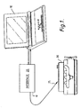
- Fig. 1 is a schematic diagram of the basic components of a computer-aided diagnostic system ;
- Fig. 2 is a schematic circuit diagram of one form of the interface device of Fig. 1;
- Fig. 3 is a schematic circuit diagram of another form of the interface device of Fig. 1;
- Fig. 4 is a flow chart of the diagnostic and tutorial software for use with the apparatus of Fig. 1;
- Fig. 5 is a schematic block diagram of a further embodiment of the invention;
- Fig. 6 is a circuit diagram of the coupling circuit of Fig. 5; and
- Fig. 7 is a schematic diagram of the interface current of Fig. 5.
- As shown in Fig. 1, the diagnostic apparatus comprises computer means 10 which may suitably be a conventional portable or laptop computer. Alternatively, a standard personal computer (PC) may be used. Such computers are commonly available and are within the financial reach of most motor repair garages. In the preferred embodiment, the computer means is a conventional
portable computer 10 which is preferably housed in a robust casing designed to withstand the harsh environment of an engine workshop. - An
interface device 20 is interposed between theengine 30 under test and theportable computer 10 to interpret switching control data from the computer means and to convert the measured values of operational parameters of theengine 30 into suitable digital form for input to, and processing by, theportable computer 10. - In a simple form of the diagnostic apparatus (hereinafter referred to as the "manual" version), the
interface device 20 can be connected to theengine 30 by means of one ormore probes 25. Typically, two probes are used, one probe being earthed, and theother probe 25 being placed manually at sensors at various locations on theengine 30 under test according to programmed instructions provided by theportable computer 10 on its associated display. - In a first preferred embodiment of the invention, the input of the
interface device 20 is connected to the multipin plug which normally connects the engine sensors to the on-board microprocessor controlling the operation of the EFI engine. In this embodiment, the input of theinterface device 20 is switched automatically between the various sensors connected to the multipin plug, the switching being controlled by theportable computer 10. In this manner, in order to diagnose theengine 30, the operator need only remove the multipin plug from the microprocessor controller on board the vehicle and connect it, via a suitable connector lead or adaptor, to theinterface device 20. The operational parameters measured by the individual sensors are then scanned sequentially and the measured data is fed via theinterface 20 to theportable computer 10 for processing. - Operational parameters are measured in real time. Typically, the diagnostic software in the
portable computer 10 is designed to compare the measured value of an operational parameter with a predetermined range. This range may be derived from manufacturer's specifications or by empirical determination. If the measured operational parameter is within the predetermined range, the diagnostic program will then proceed onto the next operational parameter. However, if the measured parameter is outside the allowable range, the program will then switch to tutorial mode to instruct the operator the required steps to locate and rectify the fault. - In a second preferred embodiment of the invention, the input of the
interface device 20 is interposed between the multipin plug and the on-board microprocessor so that not only can sensor information be received by the diagnostic computer but also test valves can be fed to the on-board microprocessor to check the proper operation thereof. - A schematic circuit diagram of one form of the
interface device 15 is shown in Fig. 2. Theinterface device 15 is basically a computer controlled multimeter which can operate as a voltmeter, ohmmeter or tachometer, together with an analog-to-digital converter 22 for converting measured valves to digital form. The interface circuit can be constructed at low cost and is suitable for small motor repair workshops. - In use, control data is fed from the
portable computer 10 to theinterface circuit 15 along "data in"line 21 in serial form. This control information is used to provide the required voltages atcontrol outputs interface 15 to operate in one of its voltmeter, ohmmeter or tachometer modes. (In the simplified schematic diagram shown in Fig. 2, the switches are shown in the form of solenoid relays. However, it will be appreciated by those skilled in the art that other suitable switching devices can be used, e.g. solid state switches.) - By way of example, if the battery is to be tested, the
portable computer 10 will instruct the operator to connect theprobe 25 to the positive battery terminal, the other probe (not shown) being earthed. Thecomputer 10 will then transmit the required control data to theinterface 15 vialine 21 so that switch 1' will be closed, and the remaining switches 2', 3', 4' will be opened bycontrol outputs probe 25 will be fed directly to the analog-to-digital (A/D)converter 22 within the interface. (Theinterface device 15 suitably comprises appropriate ranging and shaping circuits (not shown) to place the measured voltage in a suitable condition for A/D conversion). The measured voltage is then converted to digital form and fed, in serial data format, to thecomputer 10 via line 23. The value of the battery voltage will then be compared with a predetermined range previously input to the computer. - If the measured battery voltage is outside the allowable range, a FAULT message is displayed on the screen. If not, the computer proceeds to the next test. For example, it may then display instructions to the operator to start the engine, with the
probe 25 being left connected to the positive terminal of the battery. During this procedure, the battery starting and charging voltages will be measured and input to thecomputer 10 which compares them with predetermined ranges. - This procedure is continued, each operational parameter being checked sequentially to ensure that it is within a prescribed range.
- If the operational parameter to be checked is in the form of a resistance (e.g. if it is necessary to test for open or short circuits), the
interface device 15 is switched to ohmmeter mode. The control information fed bycomputer 10 alongline 21 will cause the control outputs to close switches 1' and 4', and open all other switches. A reference voltage (Vref) is applied to areference resistance 24 in order to derive a known current. This current is fed via switch 4' and probe 25 to the resistance being measured. The resulting voltage, which is proportional to the measured resistance, is input to the A/D converter 22 wherein it is converted to serial digital form and fed tocomputer 10 via output line 23. The reference voltage may be derived from a battery or reference voltage circuit within theinterface device 15, or from an external source. - If engine speed is to be measured, the
interface device 15 is switched to tachometer mode. In this mode, switches 2' and 3' are closed, and all other switches are open. Theprobe 25 is placed on a source of periodic pulses dependant on engine speed (e.g. by connecting to a spark plug, ignition coil or speed sensor). The periodic pulses sensed byprobe 25 are fed to apulse tachometer circuit 26 which provides an output voltage proportional to the frequency of the incoming pulses. The output voltage is fed via switch 2' to the input of the A/D converter 22 where it is again converted to serial digital form and fed to thecomputer 10. - The switching of the
interface device 15 between its various voltmeter, ohmmeter and tachometer modes is performed automatically under computer control, and the transmission of control and measurement data between theinterface 15 andcomputer 10 is governed by a suitable clock or timing mechanism. The operator need only shift theprobe 25 as instructed by the programmed instructions displayed on the screen of thecomputer 10. No special training or expertise is required, and the required tutorial information is able to be displayed on the screen ofcomputer 10. - The allowable range of selected operational parameters for various models of vehicles, together with diagnostic subroutines and tutorial information, can be stored on individual floppy discs, and purchased as and when required. This information can then be loaded into the computer before testing.
- It will be apparent to those skilled in the art that the foregoing provides a low cost engine diagnostic system which is simple to use.
- In the embodiment illustrated in Fig. 2, the probe is shifted manually from location to location to measure the required operational parameters sequentially. Although the interface circuit is of low cost design, the need to continually shift the
probe 25 renders the diagnostic procedure somewhat lengthy. In order to obviate this problem , an automatic version of the interface circuit is used in a preferred embodiment of the invention and is illustrated schematically in Fig. 3. - The
automatic interface 35 of Fig. 3 is adapted to receive control data in serial form fromportable computer 10 alongline 31. The serial control data is converted to parallel form by a serial-to-parallel converter incircuit 32 within theinterface 35. More specifically, the incoming serial data is converted into eight bit parallel form. The first six bits are fed vialines 33 to an A/D converter 34, and are used to select one of a possible 64 input lines to the A/D converter 34. The seventh and eighth bits are used to control the switching of fourswitches 1", 2", 3", 4" to select the appropriate mode amultimeter circuit 36, in a similar manner to that described above with reference to Fig. 2. In other words, for the selected one of a possible 64 input lines, thecircuit 36 will measure the input as a voltmeter, ohmmeter or tachometer as the case may be. The input lines are connected to amultipin socket 29. - In use, the multipin plug connected to the various sensors on the engine is disconnected from the on-board microprocessor, and reconnected to the
multipin socket 29. Control data output from the computer is used to select an appropriate incoming sensor line, i.e. the desired operational parameter, and to switch themultimeter device 36 to the appropriate measurement mode for the selected operational parameter. - The measured value on the selected line is converted into digital form by A/
D converter 34, and fed (in parallel format) alonglines 37 to a parallel-to-serial converter withincircuit 32. The output serial data is then fed tocomputer 10 alongoutput line 38. The switching of the A/D converter 34 and S/P, P/S converters 32 is also controlled by aclock 39. - Using the
automatic interface circuit 35 of Fig. 3, thecomputer 10 can rapidly measure the operational parameters of the engine under test since no manual relocation of the probe is necessary. - The measured values of the operational parameters can be processed immediately and/or stored for subsequent analysis.
- The computer can automatically compare all measured operational parameters with their respective allowable ranges, and provide a summary and fault analysis at the end of the diagnostic routine. Alternatively, the computer may measure each operational parameter individually and display the results of the diagnostic comparisons on the screen sequentially. Moreover, using a Select Menu, a particular sensor or operational parameter can be checked.
- The
automatic interface 35 is simple to use since the operator need only connect it to the on-board plug. Suitable adaptor sockets can be provided to suit the various models of plugs found on on-board microprocessors. - A flow chart of an example of suitable software for the
computer 10 is shown in Fig. 4. The software is both diagnostic and tutorial in nature. In other words, it not only locates the fault, but provides repair instructions and trouble shooting advice. - After the computer program is loaded and the connections tested, each operational parameter or device is tested sequentially. As shown in the flow chart for this example, the battery voltage is first checked. If the battery voltage is not within the prescribed range, instructions are provided for repairing the battery or the charging system of the vehicle. The earthing, ignition, starter, throttle sensor, air temperature sensor, air flow meter, coolant temperature sensor, the injectors, relay and power supply are then tested sequentially.
- For each test, tutorial information is provided on the screen of the computer to assist the operator in understanding the test being conducted. The operational parameter of the particular device under test is measured and compared with a predetermined range which has previously been entered into the computer memory. If the measured parameter is within the prescribed range, the program proceeds to the next test. If not, repair or trouble shooting instructions are provided on the screen for the operator.
- For operational parameters which can be measured by the operator, the operator is able to ascertain whether the particular sensor measuring that operational parameter is operating correctly. For example, if the reading obtained from a particular sensor is outside the prescribed range, the operational parameter can be measured directly to ascertain whether it is, in fact, incorrect or whether the sensor is faulty.
- By the process of elimination, the diagnostic equipment of the present invention can also be used to ascertain whether the on-board microprocessor is faulty.
- Furthermore, by suitable programming, the diagnostic apparatus of the present invention can be used to test itself, i.e. to test whether the interface circuit is operating correctly.
- Figs. 5 to 7 iilustrate a further preferred embodiment of the invention in which the input of the interface circuit is connected between the on-board microprocessor and the engine sensors. As shown in the schematic block diagram of Fig. 5, the
interface circuit 40 of this embodiment is connected to a portable or personal computer ("PC") 41 via a coupling circuit and receiver/line interface 42, a circuit diagram of which is shown in Fig. 6.Circuit 42 provides optical isolation between the PC and theinterface 40, and converts the signals to RS485 levels. The power for the RS485 signals is received from theinterface circuit 40 via the data cable. The RS485 interface preferably has terminating resistors and a filtering network on each input line. - The
interface 40 is connected, viacoupling circuit 42, to a parallel input/output port of the PC, for example a printer port. In the illustrated circuit, the following signal lines of the parallel I/O port of the PC are used: - D0
- Address/data line
- D1
- Data clock
- D2
- Address clock
- D3
- Power line for opto-isolators
- D4) D5)
- The system is enabled when these lines are high.
- BUSY
- Return data (reads as
BIT 7 on printer status) - The signals fed from the
coupling circuit 42 to theinterface 40 include ADDRESS/DATA, DATA CLOCK and ADDRESS CLOCK, while the signals received from theinterface 40 include RETURN DATA. - The other end of
interface 40 is connected between the plug or harness connector to which the engine sensors are connected, and the on-board microcomputer. A T-connector 43 is used to plug into the harness connector and the socket connected to the on-board computer. The T-connector 43 is typically provided in a variety of sizes and configurations to suit different models of automobile engine controllers. - The
interface circuit 40 is shown in more detail in Fig. 7. In the illustrated embodiment, the circuit has forty-eightline control circuits 50 for switching between the connections to the engine sensors and the on-board microcomputer. However, it will be apparent to those skilled in the art that the number of line control circuits can be varied to suit the particular application of the interface. The forty-eightline control circuits 50 are housed on six boards of eight circuits each. To connect theinterface 40 to a particular one of the 48 lines, the computer sends the appropriate address data to interface 40 viacoupling circuit 42. The address data is clocked and decoded and switched to the appropriate address lines by addressingcircuit 51. Address lines EH1, EH2, EH3 are used to select the particular one of the six cards to which the line is connected, while address lines A, B, C are used to select the desired one of the eight lines connected to that card. - As can be seen in Fig. 7, the
line control circuits 50 each include two relays connected in series between thesensor harness connectcr 45 and the on-board computer connector 46 for each of the forty-eight lines. A connection (MUX) is also made to each line via a 100 K ohm resistor. By appropriate switching of the pair of relays interposed in each line, various measurements of sensor outputs can be taken, and information can be fed to the on-board computer. - When both relays in the selected line are "OFF", there is a direct connection between the sensor of that line and the on-board computer, i.e. a normal connection. Voltage and pulse measurements can be taken on the line in this mode, the measurements being output on the MUX OUT line. For voltage measurements, the output voltage is fed to a first input of a two-
input multiplexer 52, the output of which is connected to a 12 bit analog-to-digital converter (ADC) 53. The digitized voltage reading is fed into a 12bit shift register 54 from which it is transmitted to the RETURN DATA line to thecoupling circuit 42 and hence thePC 41. - If pulse frequency measurements are to be taken, the output pulses on the MUX OUT line are first compared with a threshold level, and valid pulses are then counted by a suitable counter/timer circuit in
signal processing circuit 55. The counter/time circuit used in the illustrated embodiment is a triple counter/timer comprising: a first timer set up as a rate generator dividing a 1 MHz signal down to 10 KHz; a second timer set up as a hardware triggered monostable using the 10 KHz as a reference, to produce a one second output pulse; and a third timer set up as an event counter, gated, for one second, by the first timer and counting the valid pulses received. The pulse frequency is then provided by the number of pulses received in the one second interval. - The
interface circuit 40 can also be used to measure pulse length. In this case, valid pulses are fed to thesignal processing circuit 55 where the triple counter/timer is set up such that the first timer serves as a rate generator dividing 1 MHz down to 100 KHz, the second timer is not used, and the third timer is set up as a pulse counter, preloaded with a maximum count. When the rising edge of the pulse is detected, the 100 KHz pulses from the first timer decrement the count in the third timer, until the falling edge of the pulse is detected. (No further pulses are allowed through to the counter when the next rising edge is received unless the pulse length measuring circuit has been reset). To ascertain the length of the detected pulse, the final count in the third counter is deducted from the maximum count originally entered into the counter to obtain the length of the pulse in increments of 0.01 milliseconds. When the pulse length measuring circuit is reset, the third timer is again preloaded with its maximum count. - The pulse frequency and/or pulse width measurements are transferred to DATA TX shift register 56 for transmittal to the
PC 41 via the RETURN DATA line. - Open circuit voltage and pulse measurements can be taken by leaving the first relay (left hand relay as depicted in Fig. 7) OFF, i.e. maintaining the connection to the on-board computer, while switching ON the second relay (the right hand relay as depicted in Fig. 7) to break the connection between the sensor line and the on-board computer.
- To measure resistances, the relay states are reversed. That is, the second relay is switched OFF to maintain the connection to the sensor line, while the first relay is switched ON to break the connection to the on-board computer and connect the sensor line to the COMMON LINE. Resistance measurements between the sensor line and ground are taken in this mode. To obtain a resistance measurement, a 2.5 volt reference voltage is switched, via
switch 57, through a selected one of two known resistances to the COMMON LINE (which has been switched to the sensor line). Typically, the known resistance is switchable between 25 K ohm and 250 ohm. The voltage on the COMMON line is fed to the second input of two-input multiplexer 52 and converted to 12 bit digital format byADC 53. The digitized value is fed to shiftregister 54 for transmission to thePC 41 via the RETURN DATA line. The unknown resistance on the sensor line is calculated using the following formula:
- The
interface 40 also has connections for four manual probes 60 which can be placed at desired locations on the engine under test. Either 12 volts or ground can be selectively switched to the probes under computer control by theinterface 40. As shown in Fig. 7, the probe connections 60 are each connected to addressingcircuit 51 via a respective pair ofrelays relay 61 of a particular probe is operated, that probe is connected to the 12 volt battery voltage of the vehicle. On the other hand, if therelay 62 of a probe is operated, the respective probe is connected to the vehicle ground. All probe connections to the addressingcircuit 51 are protected by five Amp thermal circuit breakers 63. - It will be apparent to those skilled in the art that the
interface circuit 40 enables the computer to address a particular sensor line and take measurements of voltage, pulse width and/or frequency and resistance on that line simply by switching of the appropriate relays. Selected voltages can also be switched to the manual probes under computer control. Thus, under control of appropriate software onPC 41, theinterface circuit 40 is able to automatically access all sensor lines and take the appropriate readings, which are then relayed back to the PC for diagnostic assessment. - Furthermore, the sensor lines can be isolated, and specified values can be fed to the on-board microcomputer with resultant monitoring of the microcomputer output as evidenced by the engine performance. In this manner, the diagnostic system of the abovedescribed embodiment is able to not only locate faults in the engine sensors, but also in the operation of the on-board computer.
Claims (14)
- Apparatus for diagnosing an internal combustion engine having a plurality of sensors connected to an on-board microcomputer via a multiwire connector, the apparatus comprising: independent external computer means (10) having a display; input means having a multiple input connector (29) suitable for connection to the multiwire connector; and an interface circuit (35) connected between the computer means (10) and the input means (29), the interface circuit (35) comprising a multimode measuring means (36) responsive to the computer means (10) to switch to a selected one of a plurality of measurement modes, said modes including a mode measuring voltage, a mode measuring current or resistance, and a mode measuring pulse rate and producing a single analog output, a switching circuit (1", 2", 3", 4") responsive to the computer means (10) to selectively connect the measurement means (36) to a selected input of the multiple input connector (29), the output of the measurement means (36) being connected to an analog-to-digital converter (34) for converting to digital form the value, as measured by the measurement means (36), of an operational parameter sensed by a sensor corresponding to the selected input, and output means (38) for outputting the digitised measured value directly to the computer means; wherein in use, the computer means (10) is programmed to perform a diagnostic comparison of the measured value with a predetermined range of values supplied by the user and to display the result of such diagnostic comparison on the display.
- Apparatus as claimed in claim 1 wherein the computer means is a portable computer means.
- Apparatus as claimed in claim 2 wherein the measurement modes of the measurement means include voltage, frequency and resistance measurement.
- Apparatus as claimed in claim 1 wherein the input means also includes at least one manually positionable probe (25).
- Apparatus as claimed in claim 1 wherein the computer means is programmed to automatically switch the measurement means sucessively to a plurality of inputs and to the respective measurement modes corresponding to those inputs.
- Apparatus according to claim 1 for diagnosing an internal combustion engine having a plurality of sensors connected to an on-board microcomputer via a two-part multiwire connector, wherein the input means has a multiple input connector (43) connected between the two parts of the multiwire connector, and the switching circuit has first switching means (50) responsive to the computer means for selectively connecting each input of the multiple input connector to a respective sensor and/or the respective sensor's connection to the on-board computer; and second switching means (55) responsive to the computer means to selectively connect the measurement means to a selected input of the multiple input connector.
- Apparatus as claimed in claim 6, wherein the first switching means is also responsive to the computer means to connect a selected sensor to its respective connection to the on-board microcomputer.
- Apparatus as claimed in claim 6, wherein the computer means is a portable computer means.
- Apparatus as claimed in claim 6, wherein the measurement modes of the measurement means include voltage, frequency and resistance measurement.
- Apparatus as claimed in claim 6, wherein the input means also includes at least one manually positionable probe.
- Apparatus as claimed in claim 6, wherein the first switching means comprises a plurality of switching circuits each connected between a respective pair of terminals on the first and second parts, respectively of the multiwire connector, each circuit being connected to a respective input of the multiple input connector and comprising two series-connected switches independently controllable by the computer means to connect each pair of terminals to each other or individually to the respective input.
- A method of using the apparatus of claim 6 to diagnose an internal combustion engine having a plurality of sensors connected to an on-board microcomputer, the method comprising the steps of switching the first and second switching means under control of the computer means to connect the measurement means successively to selected sensors and/or the on-board microcomputer, and measuring operational parameters of the engine as sensed by the selected sensors, providing the measured values to the computer means, peforming a software comparison of the measured values with respective predetermined ranges stored in the computer means, displaying the results of such comparisons on a computer display with tutorial instructions for repair of troubleshooting in the event that a measured value does not fall within its respective predetermined range.
- A method as claimed in claim 12, wherein the computer means is a portable computer means.
- A method as claimed in claim 12, further comprising the step of inputting data to the on-board microcomputer and measuring resultant operational parameters sensed by respective sensors.
Applications Claiming Priority (4)
| Application Number | Priority Date | Filing Date | Title |
|---|---|---|---|
| AUPJ458489 | 1989-06-07 | ||
| AU4584/89 | 1989-06-07 | ||
| PCT/AU1990/000247 WO1990015316A1 (en) | 1989-06-07 | 1990-06-07 | Computer-aided engine diagnostic system |
| AU57373/90A AU647393B2 (en) | 1989-06-07 | 1990-06-07 | Computer-aided engine diagnostic system |
Publications (3)
| Publication Number | Publication Date |
|---|---|
| EP0475975A1 EP0475975A1 (en) | 1992-03-25 |
| EP0475975A4 EP0475975A4 (en) | 1992-09-16 |
| EP0475975B1 true EP0475975B1 (en) | 1996-09-25 |
Family
ID=25631614
Family Applications (1)
| Application Number | Title | Priority Date | Filing Date |
|---|---|---|---|
| EP90908426A Expired - Lifetime EP0475975B1 (en) | 1989-06-07 | 1990-06-07 | Computer-aided engine diagnostic system |
Country Status (3)
| Country | Link |
|---|---|
| EP (1) | EP0475975B1 (en) |
| AU (1) | AU647393B2 (en) |
| WO (1) | WO1990015316A1 (en) |
Families Citing this family (4)
| Publication number | Priority date | Publication date | Assignee | Title |
|---|---|---|---|---|
| US5214582C1 (en) * | 1991-01-30 | 2001-06-26 | Edge Diagnostic Systems | Interactive diagnostic system for an automobile vehicle and method |
| GB2267983A (en) * | 1992-06-10 | 1993-12-22 | Automobile Ass Limited The | Diagnostic programs. |
| FR2777356B1 (en) * | 1998-04-10 | 2000-06-02 | Renault | DEVICE FOR CONTROLLING AN ELECTRICAL BEAM AND METHOD OF USING SUCH A DEVICE |
| CN111886552B (en) * | 2017-06-08 | 2024-03-26 | 康明斯公司 | Diagnostic system and method for isolating failure modes of a vehicle |
Family Cites Families (9)
| Publication number | Priority date | Publication date | Assignee | Title |
|---|---|---|---|---|
| DE2824190A1 (en) * | 1978-06-02 | 1979-12-06 | Bosch Gmbh Robert | MICRO COMPUTER SYSTEM FOR THE CONTROL OF OPERATING PROCEDURES IN MOTOR VEHICLES, WITH A DIAGNOSTIC DEVICE FOR CHECKING THE VEHICLE |
| JPS57187751A (en) * | 1981-05-13 | 1982-11-18 | Hitachi Ltd | Vehicle engine controller |
| US4470016A (en) * | 1982-03-29 | 1984-09-04 | United Technologies Corporation | Portable probe carrier |
| JPS6035239A (en) * | 1983-08-05 | 1985-02-23 | Fujitsu Ltd | Checking and diagnosing system for automobile |
| GB8509488D0 (en) * | 1985-04-12 | 1985-05-15 | Massey Ferguson Services Nv | Vehicle performance monitoring apparatus |
| US4821217A (en) * | 1987-01-12 | 1989-04-11 | The Boeing Company | Programmable jet engine test station |
| JPH0827221B2 (en) * | 1987-09-22 | 1996-03-21 | 富士重工業株式会社 | Vehicle diagnostic device |
| JPH0752141B2 (en) * | 1987-12-11 | 1995-06-05 | 富士重工業株式会社 | Vehicle diagnostic system |
| JPH0776724B2 (en) * | 1988-02-18 | 1995-08-16 | 富士重工業株式会社 | Vehicle diagnostic device |
-
1990
- 1990-06-07 WO PCT/AU1990/000247 patent/WO1990015316A1/en active IP Right Grant
- 1990-06-07 EP EP90908426A patent/EP0475975B1/en not_active Expired - Lifetime
- 1990-06-07 AU AU57373/90A patent/AU647393B2/en not_active Expired
Also Published As
| Publication number | Publication date |
|---|---|
| WO1990015316A1 (en) | 1990-12-13 |
| EP0475975A1 (en) | 1992-03-25 |
| AU5737390A (en) | 1991-01-07 |
| EP0475975A4 (en) | 1992-09-16 |
| AU647393B2 (en) | 1994-03-24 |
Similar Documents
| Publication | Publication Date | Title |
|---|---|---|
| US5318449A (en) | Method and apparatus for computer-aided diagnosis of engines | |
| EP0286648B1 (en) | System for diagnosing anomalies or breakdowns in a plurality of types of electronic control systems installed in motor vehicles | |
| US5214582A (en) | Interactive diagnostic system for an automotive vehicle, and method | |
| US6988053B2 (en) | Combined off-board device and starter/charging/battery system tester | |
| US4423378A (en) | Automotive battery test apparatus | |
| US5532927A (en) | Automotive diagnostic tool | |
| US5107428A (en) | Process and apparatus for diagnosis of defects in electric or electronic modules in automotive vehicles | |
| US4926330A (en) | Diagnosis system for a motor vehicle | |
| US8838328B2 (en) | Automotive diagnostic system | |
| JP3271144B2 (en) | Automated breakout boxes for automotive testing | |
| US20020004694A1 (en) | Modular automotive diagnostic system | |
| JPS5946346B2 (en) | Automotive electrical system tester | |
| AU551375B2 (en) | Ignition coil test apparatus | |
| US5315252A (en) | Automotive test system with input protection | |
| EP0475975B1 (en) | Computer-aided engine diagnostic system | |
| JPS62500473A (en) | Control device inspection method | |
| JPH07159474A (en) | Device for diagnosing electrical wiring of vehicle | |
| JP3025300B2 (en) | Computer-aided engine diagnostic system | |
| RU99075U1 (en) | DEVICE FOR COMPUTER DIAGNOSTICS OF ICE | |
| US4385278A (en) | Testing apparatus for an electronic ignition system for an internal combustion engine | |
| Pupala et al. | Review Paper on Vehicle Diagnosis with Electronic Control Unit | |
| GB2221544A (en) | Vehicle fault recorder | |
| KR970010786B1 (en) | Diagnosis device of a car | |
| Carp et al. | A Low-Cost Interactive Diagnostic Tester | |
| JPS6311332Y2 (en) |
Legal Events
| Date | Code | Title | Description |
|---|---|---|---|
| PUAI | Public reference made under article 153(3) epc to a published international application that has entered the european phase |
Free format text: ORIGINAL CODE: 0009012 |
|
| 17P | Request for examination filed |
Effective date: 19920104 |
|
| AK | Designated contracting states |
Kind code of ref document: A1 Designated state(s): AT BE CH DE ES FR GB IT LI SE |
|
| RIN1 | Information on inventor provided before grant (corrected) |
Inventor name: MCLEISH, GARY, IAN Inventor name: ANDREWS, CARL, DAVID Inventor name: SCHOELL, EDWIN, THEODORE |
|
| A4 | Supplementary search report drawn up and despatched |
Effective date: 19920724 |
|
| AK | Designated contracting states |
Kind code of ref document: A4 Designated state(s): AT BE CH DE ES FR GB IT LI SE |
|
| 17Q | First examination report despatched |
Effective date: 19940121 |
|
| GRAH | Despatch of communication of intention to grant a patent |
Free format text: ORIGINAL CODE: EPIDOS IGRA |
|
| GRAA | (expected) grant |
Free format text: ORIGINAL CODE: 0009210 |
|
| GRAH | Despatch of communication of intention to grant a patent |
Free format text: ORIGINAL CODE: EPIDOS IGRA |
|
| AK | Designated contracting states |
Kind code of ref document: B1 Designated state(s): AT BE CH DE ES FR GB IT LI SE |
|
| PG25 | Lapsed in a contracting state [announced via postgrant information from national office to epo] |
Ref country code: LI Effective date: 19960925 Ref country code: ES Free format text: THE PATENT HAS BEEN ANNULLED BY A DECISION OF A NATIONAL AUTHORITY Effective date: 19960925 Ref country code: CH Effective date: 19960925 Ref country code: BE Effective date: 19960925 Ref country code: AT Effective date: 19960925 |
|
| REF | Corresponds to: |
Ref document number: 143491 Country of ref document: AT Date of ref document: 19961015 Kind code of ref document: T |
|
| REF | Corresponds to: |
Ref document number: 69028703 Country of ref document: DE Date of ref document: 19961031 |
|
| ITF | It: translation for a ep patent filed |
Owner name: STUDIO TORTA SOCIETA' SEMPLICE |
|
| PG25 | Lapsed in a contracting state [announced via postgrant information from national office to epo] |
Ref country code: SE Effective date: 19961225 |
|
| ET | Fr: translation filed | ||
| REG | Reference to a national code |
Ref country code: CH Ref legal event code: PL |
|
| PLBQ | Unpublished change to opponent data |
Free format text: ORIGINAL CODE: EPIDOS OPPO |
|
| PLBI | Opposition filed |
Free format text: ORIGINAL CODE: 0009260 |
|
| PLBF | Reply of patent proprietor to notice(s) of opposition |
Free format text: ORIGINAL CODE: EPIDOS OBSO |
|
| 26 | Opposition filed |
Opponent name: EDGE DIAGNOSTIC SYSTEMS Effective date: 19970625 |
|
| PLBF | Reply of patent proprietor to notice(s) of opposition |
Free format text: ORIGINAL CODE: EPIDOS OBSO |
|
| PLBF | Reply of patent proprietor to notice(s) of opposition |
Free format text: ORIGINAL CODE: EPIDOS OBSO |
|
| PLBO | Opposition rejected |
Free format text: ORIGINAL CODE: EPIDOS REJO |
|
| APAC | Appeal dossier modified |
Free format text: ORIGINAL CODE: EPIDOS NOAPO |
|
| APAE | Appeal reference modified |
Free format text: ORIGINAL CODE: EPIDOS REFNO |
|
| APAC | Appeal dossier modified |
Free format text: ORIGINAL CODE: EPIDOS NOAPO |
|
| PLBN | Opposition rejected |
Free format text: ORIGINAL CODE: 0009273 |
|
| STAA | Information on the status of an ep patent application or granted ep patent |
Free format text: STATUS: OPPOSITION REJECTED |
|
| 27O | Opposition rejected |
Effective date: 19991212 |
|
| PGFP | Annual fee paid to national office [announced via postgrant information from national office to epo] |
Ref country code: DE Payment date: 20000828 Year of fee payment: 11 |
|
| REG | Reference to a national code |
Ref country code: GB Ref legal event code: IF02 |
|
| PG25 | Lapsed in a contracting state [announced via postgrant information from national office to epo] |
Ref country code: DE Free format text: LAPSE BECAUSE OF NON-PAYMENT OF DUE FEES Effective date: 20020403 |
|
| PGFP | Annual fee paid to national office [announced via postgrant information from national office to epo] |
Ref country code: GB Payment date: 20020607 Year of fee payment: 13 |
|
| PGFP | Annual fee paid to national office [announced via postgrant information from national office to epo] |
Ref country code: FR Payment date: 20020610 Year of fee payment: 13 |
|
| PG25 | Lapsed in a contracting state [announced via postgrant information from national office to epo] |
Ref country code: GB Free format text: LAPSE BECAUSE OF NON-PAYMENT OF DUE FEES Effective date: 20030607 |
|
| GBPC | Gb: european patent ceased through non-payment of renewal fee |
Effective date: 20030607 |
|
| PG25 | Lapsed in a contracting state [announced via postgrant information from national office to epo] |
Ref country code: FR Free format text: LAPSE BECAUSE OF NON-PAYMENT OF DUE FEES Effective date: 20040227 |
|
| REG | Reference to a national code |
Ref country code: FR Ref legal event code: ST |
|
| PG25 | Lapsed in a contracting state [announced via postgrant information from national office to epo] |
Ref country code: IT Free format text: LAPSE BECAUSE OF NON-PAYMENT OF DUE FEES;WARNING: LAPSES OF ITALIAN PATENTS WITH EFFECTIVE DATE BEFORE 2007 MAY HAVE OCCURRED AT ANY TIME BEFORE 2007. THE CORRECT EFFECTIVE DATE MAY BE DIFFERENT FROM THE ONE RECORDED. Effective date: 20050607 |
|
| APAH | Appeal reference modified |
Free format text: ORIGINAL CODE: EPIDOSCREFNO |