EP0474492B1 - Two degrees of freedom type control system - Google Patents
Two degrees of freedom type control system Download PDFInfo
- Publication number
- EP0474492B1 EP0474492B1 EP91308139A EP91308139A EP0474492B1 EP 0474492 B1 EP0474492 B1 EP 0474492B1 EP 91308139 A EP91308139 A EP 91308139A EP 91308139 A EP91308139 A EP 91308139A EP 0474492 B1 EP0474492 B1 EP 0474492B1
- Authority
- EP
- European Patent Office
- Prior art keywords
- deviation
- target variable
- variable
- computed
- value
- Prior art date
- Legal status (The legal status is an assumption and is not a legal conclusion. Google has not performed a legal analysis and makes no representation as to the accuracy of the status listed.)
- Expired - Lifetime
Links
- 238000000034 method Methods 0.000 claims description 36
- 230000008569 process Effects 0.000 claims description 29
- 230000004044 response Effects 0.000 claims description 17
- 238000009499 grossing Methods 0.000 claims description 4
- 238000010276 construction Methods 0.000 description 9
- 230000008859 change Effects 0.000 description 7
- 238000010586 diagram Methods 0.000 description 6
- 238000013459 approach Methods 0.000 description 4
- 238000013461 design Methods 0.000 description 4
- 238000012546 transfer Methods 0.000 description 4
- 239000003990 capacitor Substances 0.000 description 2
- 230000014509 gene expression Effects 0.000 description 2
- 230000006872 improvement Effects 0.000 description 2
- 239000004065 semiconductor Substances 0.000 description 2
- 230000001629 suppression Effects 0.000 description 2
- 230000000694 effects Effects 0.000 description 1
- 238000002474 experimental method Methods 0.000 description 1
- 238000009926 jugging Methods 0.000 description 1
- 238000004886 process control Methods 0.000 description 1
- 238000012545 processing Methods 0.000 description 1
- 230000035939 shock Effects 0.000 description 1
Images


Classifications
-
- G—PHYSICS
- G05—CONTROLLING; REGULATING
- G05B—CONTROL OR REGULATING SYSTEMS IN GENERAL; FUNCTIONAL ELEMENTS OF SUCH SYSTEMS; MONITORING OR TESTING ARRANGEMENTS FOR SUCH SYSTEMS OR ELEMENTS
- G05B15/00—Systems controlled by a computer
-
- G—PHYSICS
- G05—CONTROLLING; REGULATING
- G05B—CONTROL OR REGULATING SYSTEMS IN GENERAL; FUNCTIONAL ELEMENTS OF SUCH SYSTEMS; MONITORING OR TESTING ARRANGEMENTS FOR SUCH SYSTEMS OR ELEMENTS
- G05B13/00—Adaptive control systems, i.e. systems automatically adjusting themselves to have a performance which is optimum according to some preassigned criterion
- G05B13/02—Adaptive control systems, i.e. systems automatically adjusting themselves to have a performance which is optimum according to some preassigned criterion electric
- G05B13/0265—Adaptive control systems, i.e. systems automatically adjusting themselves to have a performance which is optimum according to some preassigned criterion electric the criterion being a learning criterion
- G05B13/0275—Adaptive control systems, i.e. systems automatically adjusting themselves to have a performance which is optimum according to some preassigned criterion electric the criterion being a learning criterion using fuzzy logic only
-
- G—PHYSICS
- G05—CONTROLLING; REGULATING
- G05B—CONTROL OR REGULATING SYSTEMS IN GENERAL; FUNCTIONAL ELEMENTS OF SUCH SYSTEMS; MONITORING OR TESTING ARRANGEMENTS FOR SUCH SYSTEMS OR ELEMENTS
- G05B11/00—Automatic controllers
- G05B11/01—Automatic controllers electric
- G05B11/36—Automatic controllers electric with provision for obtaining particular characteristics, e.g. proportional, integral, differential
- G05B11/42—Automatic controllers electric with provision for obtaining particular characteristics, e.g. proportional, integral, differential for obtaining a characteristic which is both proportional and time-dependent, e.g. P. I., P. I. D.
-
- Y—GENERAL TAGGING OF NEW TECHNOLOGICAL DEVELOPMENTS; GENERAL TAGGING OF CROSS-SECTIONAL TECHNOLOGIES SPANNING OVER SEVERAL SECTIONS OF THE IPC; TECHNICAL SUBJECTS COVERED BY FORMER USPC CROSS-REFERENCE ART COLLECTIONS [XRACs] AND DIGESTS
- Y10—TECHNICAL SUBJECTS COVERED BY FORMER USPC
- Y10S—TECHNICAL SUBJECTS COVERED BY FORMER USPC CROSS-REFERENCE ART COLLECTIONS [XRACs] AND DIGESTS
- Y10S706/00—Data processing: artificial intelligence
- Y10S706/90—Fuzzy logic
-
- Y—GENERAL TAGGING OF NEW TECHNOLOGICAL DEVELOPMENTS; GENERAL TAGGING OF CROSS-SECTIONAL TECHNOLOGIES SPANNING OVER SEVERAL SECTIONS OF THE IPC; TECHNICAL SUBJECTS COVERED BY FORMER USPC CROSS-REFERENCE ART COLLECTIONS [XRACs] AND DIGESTS
- Y10—TECHNICAL SUBJECTS COVERED BY FORMER USPC
- Y10S—TECHNICAL SUBJECTS COVERED BY FORMER USPC CROSS-REFERENCE ART COLLECTIONS [XRACs] AND DIGESTS
- Y10S706/00—Data processing: artificial intelligence
- Y10S706/902—Application using ai with detail of the ai system
- Y10S706/903—Control
Definitions
- This invention relates to a process control system, and more particularly to a two degrees of freedom type control system.
- a conventional two degrees of freedom type control system having a target variable filter is constructed as shown in Figure 1.
- Such a filter is disclosed in document EP-A- 333 477. That is to say, this control system introduces the target variable SV to target variable filter unit 21, and obtains arithmetic target variable SVo by executing arithmetic processing which imparts 2 degrees of freedom to the proportional gain. Then, it introduces this arithmetic target variable SVo and process variable PV from process system 22 to deviate operation unit 23 and obtains deviation E through the (SVo - PV) operation. Next, deviation E obtained by deviation operation unit 23 is introduced into PI control unit 24 which has a transfer function of Kp ⁇ 1 + 1/(T I ⁇ S) ⁇ .
- Kp is the proportional gain
- T I is the integral time
- S is the Laplace operator.
- target variable filter unit 21 which includes coefficient unit 11,subtractor unit 12, first order lag element 13, and adder unit 14.
- Coefficient unit 11 multiplies target variable SV introduced from outside by the coefficient ⁇ which imparts 2 degrees of freedom to the proportional gain.
- Subtractor unit 12 subtracts the output of coefficient unit 11, from target variable SV.
- First order lag element 13 outputs by executing a first order lag operation to make the integral time for the output of subtractor unit 12 a time constant.
- Adder unit 14 obtains arithmetic target variable SVo by adding the output of first order lag element 13 and the output of coefficient unit 11.
- the PV ⁇ SV transfer function C PM (S) and the SV ⁇ MV transfer function C SM (S) become respectively
- ⁇ is the coefficient which imparts 2 degrees of freedom to the proportional gain (a constant capable of being set between 0 and 1). Therefore, 2 degrees of freedom can be achieved if the coefficient ⁇ which imparts 2 degrees of freedom to the proportional gain is determined so that the target variable follow-up characteristic becomes optimum after Kp and T I have been determined so that the disturbance suppression characteristic becomes optimum.
- the above target variable filter type control system with 2 degrees of freedom has excellent characteristics which simultaneously optimise the disturbance suppression characteristic and the target variable follow-up characteristic.
- target variable filter unit 21 When studying the cause of this, there is at least a first order lag element in target variable filter unit 21.
- the target variable SV of this change When a target variable SV is changed to a stepped state, the target variable SV of this change is subjected to the influence of the first order lag element. Therefore, it takes some time until the final value is reached.
- FIG.2 shows the state when target variable SV in the system in FIG.1 is caused to vary in step form. Only the output, (SV ⁇ ⁇ ) of coefficient unit 1, varies in step form. However, the output, ⁇ SV ⁇ (1 - ⁇ ) ⁇ , of subtractor unit 12 undergoes the influence of first order lag element 13 and gradually rises to approach target variable SV.
- a system for controlling a process system subject to an external disturbance by adjusting a process variable output by the process system to a given target variable comprising target variable filter means for generating a computed target variable to perform a compensation control operation; deviation operation means for computing a deviation between the process variable and the computed target variable inputted from the target variable filter means; and main control means for performing at least proportional and integral control operations on the computed deviation between the process variable and the computed target variable inputted from the deviation operation means to suppress fluctuation of the process variable produced by the external disturbance; characterised in target variable control means for changing the input into the deviation operation means from the computed target variable to the given target variable either at the moment when the deviation between the given target variable and the computed target variable computed by the target variable filter means is less than a predetermined value or gradually, at a predetermined speed rate, after the deviation between the given target variable and the computed target variable has become less than a predetermined value.
- a method of controlling a process system subject to an external disturbance by adjusting according to a deviation output by a deviation operation means, a process variable output by the process system to a given target variable comprises the steps of generating a computed target variable to perform a compensation control operation; computing a deviation between the process variable and the computed target variable inputted into the deviation operation means; performing at least proportional and integral control operations on the computed deviation between the process variable and the computed target variable inputted from the deviation operation means to suppress fluctuation of the process variable produced by the external disturbance; and changing the input into the deviation operation means from the computed target variable to the given target variable either at the moment when a deviation between the given target variable and the computed target variable is less than a predetermined computed target variable is less than a predetermined value or gradually, at a predetermined speed rate, after a deviation between the given target variable and the computed target variable has become less than a predetermined value.
- FIG. 3 An embodiment of this invention is described below with reference to FIG. 3.
- the same symbols are used and detailed descriptions are omitted where components are the same as those in FIG.1.
- the following is mainly a description of those components which differ from prior art.
- comparator unit 11 is provided between the control target variable input terminal and the output terminal of adder unit 14, for jugging whether or not the deviation between control target variable SV and arithmetic target variable SVo, which is the output of target variable filter unit 21, is less than a pre-determined set value.
- signal switching unit 12 is provided for introducing judgement values to deviation operation unit 23. When the above deviation is greater than the specified value in comparator unit 11, signal switching unit 12 receives a switching command and selects arithmetic target variable SVo. Also, when the deviation is smaller than the set value, it receives a switching command and selects control target variable SV.
- comparator unit 11 compares the size relationship between a specified value and the deviation signal due to target variable SV and arithmetic target variable SVo. Since this is immediately after the change to step form, the relationship is
- signal switching unit 12 receives the output of comparator unit 11 and selects and outputs arithmetic target variable SVo. Therefore, in this case, target variable SVa for PI control unit 24 becomes SVo.
- specified value ⁇ is a value which has no effect on the 2 degrees of freedom, and it is determined on the basis of experiment and past experience.
- comparator unit 11 compares the specified value ⁇ with the deviation between target variable SV and arithmetic target variable SVo.
- the relationship becomes
- signal switching unit 12 receives this switching command and selects control target variable SV.
- comparator unit 11 and signal switching unit 12 may be achieved by hardware using resistors, capacitors and semiconductors. They may also be achieved by software using a computer.
- Subtractor unit 31 subtracts arithmetic target variable SVo from target variable SV.
- Adder unit 33 adds the output obtained from subtractor unit 31 via signal switching unit 32 and arithmetic target variable SVo which is the output of target variable filter unit 21.
- the construction is such that the output of adder unit 33 is introduced into deviation operation unit 23 as the target variable for PI control.
- this embodiment is provided with the function of judging whether or not to add the deviation between control target variable SV and arithmetic target variable SVo to arithmetic target variable SVo.
- arithmetic target variable SVo which is outputted from target variable filter unit 21 is introduced into deviation operation unit 23 as target variable SVa for PI control via adder unit 33.
- comparator unit 11 compares a specified value ⁇ and the deviation between target variable SV and arithmetic target variable SVo. Since this is immediately after the change to step form, the relationship is
- ⁇ ⁇ Since no switching command is generated from comparator unit 11, signal switching unit 32 is in a non-conductive state. As a result, SVa SVo is transmitted to deviation operation unit 23 as the target variable for PI control.
- comparator unit 11 compares the specified value ⁇ with the deviation between target variable SV and arithmetic target variable SVo.
- signal switching unit 32 becomes in a conductive state and introduces the subtraction signal (SV - SVo) from subtractor unit 31 to adder unit 33.
- arithmetic target variable SVo is introduced into deviation operation unit 23.
- the design is such that, when the deviation between target variable SV and arithmetic target variable SVo becomes less than specified value ⁇ , the subtraction signal (SV - SVo) is added to SVo.
- the target variable for PI control can be supplied to deviation operation unit 23 without any loss of time.
- This embodiment uses almost the same construction as in FIG.5. The particular difference is that first order lag element 41 is added at the input side of adder unit 33.
- comparator unit 11 compares specified value ⁇ with the deviation between target variable SV and arithmetic target variable SVo.
- First order lag element 41 is provided on the input side of adder unit 33.
- the first order lag element may also be provided on the contact b side of signal switching unit 12 shown in FIG.3.
- PI control operation has been described in the above embodiments.
- this invention can also be applied in the same way in PID ( D : derivative) control operation.
- the response time for the change of target value can be greately reduced within limits which do not interfere with the original function of imparting 2 degrees of freedom, and the target variable for control can be settled at the control target variable.
- the target variable for control can be transferred to the control target variable without any loss of time.
- the deviation between the target variable control and the control target variable becomes less than a specified value, it can be transferred smoothly to the control target variable by smoothing the target variable for control.
- the target variable follow-up time for changes of target variable can be greatly reduced. Also, the performance of a control system fitted with a target variable filter unit can be greatly improved. Therefore, a higher performance of plant operating characteristics can be achieved by providing the above inventions throughout the plant.
- FIG.7 An embodiment of this invention is described below with reference to FIG. 7.
- FIG.7 the same symbols are used and detailed descriptions are omitted where components are the same as those in FIG.1.
- the following is mainly a description of those components which differ from prior art.
- this system is provided with subtractor unit 51 between the control target variable input terminal and the output terminal of adder unit 14.
- absolute value unit 52 is provided at the output side of subtractor unit 51.
- the design is that absolute value
- membership function m( ⁇ ) which takes a value from 0 to 1 in response to the absolute value is determined beforehand.
- Fuzzy coefficient setting unit 53 is provided which outputs membership function m( ⁇ ) in response to the absolute value
- adder unit 55 which makes the target variable SVa for PI control by adding the multiplication value obtained by multiplication unit 54 and arithmetic target variable SVo is also provided.
- the deviation ⁇ SV - SVo between control target variable SV and arithmetic target variable SVo is obtained by subtractor unit 51 for the variation of the step form of control target variable SV. Then, this deviation ⁇ is transmitted to absolute value unit 52 and multiplication unit 54. After the absolute Value
- the fuzzy coefficient setting unit 53, etc, may be achieved by hardware using resistors, capacitors and semiconductors. They may also be achieved by means of software using a computer.
- this embodiment is a design in which absolute value unit 52 is omitted from FIG.7. Because of this, fuzzy coefficient setting unit 53′ individually sets membership functions m( ⁇ ) in response to the sign of the deviation between control target variable SV and arithmetic target variable SVo. The membership functions m( ⁇ ) for plus and minus are set so that they differ.
- the design is that target variable SVa for PI control is forcibly and rapidly transferred to control target variable SV from the arithmetic target variable SVo of target variable filter unit 21 using the membership function, when arithmetic target variable SVo of target variable filter unit 21 approaches control target variable SV, that is to say when the deviation between the two target variables becomes less than specified value ⁇ 2 . Therefore, the target variable follow-up time can be greatly reduced without any influence on the function of 2 degrees of freedom. Thus, the performance of this type of control device with 2 degrees of freedom can be greatly improved. Therefore, the provision of these systems throughout a plant can greatly contribute to improvement of the plant operating characteristics.
- the above embodiment are designed to supply the multiplication variable of the output of subtactor unit 51 and the membership function to adder unit 55.
- they may also be designed to eliminate multiplication unit 54 and to output values equivalent to the multiplication variable from fuzzy coefficient setting units 53 and 53′ and then add them in adder unit 55.
- PI control operation has been described in the above embodiments. However, needless to say, this invention can also applied in the same way for PID control operation.
- a fuzzy combination type control system with 2 degrees of freedom can be provided which can greatly reduce the response time for variation of the target variable compared with the prior art, and thus contributes greatly to the improvement of performance.
Landscapes
- Engineering & Computer Science (AREA)
- Physics & Mathematics (AREA)
- Artificial Intelligence (AREA)
- General Physics & Mathematics (AREA)
- Automation & Control Theory (AREA)
- Software Systems (AREA)
- Mathematical Physics (AREA)
- Fuzzy Systems (AREA)
- Health & Medical Sciences (AREA)
- Computer Vision & Pattern Recognition (AREA)
- Evolutionary Computation (AREA)
- Medical Informatics (AREA)
- General Engineering & Computer Science (AREA)
- Feedback Control In General (AREA)
Description
- This invention relates to a process control system, and more particularly to a two degrees of freedom type control system.
- A conventional two degrees of freedom type control system having a target variable filter is constructed as shown in Figure 1. Such a filter is disclosed in document EP-A- 333 477. That is to say, this control system introduces the target variable SV to target
variable filter unit 21, and obtains arithmetic target variable SVo by executing arithmetic processing which imparts 2 degrees of freedom to the proportional gain. Then, it introduces this arithmetic target variable SVo and process variable PV fromprocess system 22 to deviateoperation unit 23 and obtains deviation E through the (SVo - PV) operation. Next, deviation E obtained bydeviation operation unit 23 is introduced intoPI control unit 24 which has a transfer function of Kp { 1 + 1/(TI · S)}. Here, manipulating variable MV is obtained by executing PI control operation. Then, the construction is such that, after the addition of manipulating variable MV and disturbance D byadder unit 25, control is executed to make arithmetic target variable SVo = control variable PV by impressing this addition result onprocess system 22. In the above equation, Kp is the proportional gain, TI is the integral time, and S is the Laplace operator. - Also, target
variable filter unit 21 which includescoefficient unit 1₁,subtractor unit 1₂, firstorder lag element 1₃, andadder unit 1₄. -
Coefficient unit 1₁ multiplies target variable SV introduced from outside by the coefficient α which imparts 2 degrees of freedom to the proportional gain.Subtractor unit 1₂ subtracts the output ofcoefficient unit 1₁, from target variable SV. Firstorder lag element 1₃ outputs by executing a first order lag operation to make the integral time for the output of subtractor unit 1₂ a time constant. Adderunit 1₄ obtains arithmetic target variable SVo by adding the output of firstorder lag element 1₃ and the output ofcoefficient unit 1₁. - Therefore, in the case of the above construction, the PV → SV transfer function CPM(S) and the SV → MV transfer function CSM(S) become respectively


α is the coefficient which imparts 2 degrees of freedom to the proportional gain (a constant capable of being set between 0 and 1). Therefore, 2 degrees of freedom can be achieved if the coefficient α which imparts 2 degrees of freedom to the proportional gain is determined so that the target variable follow-up characteristic becomes optimum after Kp and TI have been determined so that the disturbance suppression characteristic becomes optimum. - The above target variable filter type control system with 2 degrees of freedom has excellent characteristics which simultaneously optimise the disturbance suppression characteristic and the target variable follow-up characteristic. However, there is the problem of requiring a long time for the settling of target variable SV.
- When studying the cause of this, there is at least a first order lag element in target
variable filter unit 21. When a target variable SV is changed to a stepped state, the target variable SV of this change is subjected to the influence of the first order lag element. Therefore, it takes some time until the final value is reached. - Moreover, the influence of first order lag is explained using the response characteristic in FIG. 2. That is to say, FIG.2 shows the state when target variable SV in the system in FIG.1 is caused to vary in step form. Only the output, (SV · α) of
coefficient unit 1, varies in step form. However, the output, {SV · (1 - α)}, ofsubtractor unit 1₂ undergoes the influence of firstorder lag element 1₃ and gradually rises to approach target variable SV. - Thus, taking SV = X and SVo = Y, when target
variable filter unit 21 shown in FIG.1 is expressed as a digital arithmetic expression, it becomes
If Equation (3) is expressed as a differential equation, it becomes
Here, if the relational expressions
are substituted in Equation (4),
can be obtained. Moreover, if this equation is transformed,
can be obtained.
When target variable SV is varied in step form at time n = 1, Xn becomes Xn = Xn-1 at n > 2. Thus, the response characteristic in FIG.2 becomes
from Equation (6). Since Δt in Equation (7) is very much smaller than TI, and (Xn- yn-1) is also small, the values of the later stages in this equation become very much smaller. Moreover, the closer output yn-1 approaches input Xn, the smaller the variation of Δyn becomes. As a result, it requires a relatively long time until output yn agrees with input Xn. Naturally, since this output yn is the target variable ofPI control unit 24, the settling time becomes extremely long. - It is an object of this invention to improve the controllability of a target variable follow-up characteristic of a two degrees of freedom type control system.
- The foregoing objects are achieved according to one aspect of the invention by providing a system for controlling a process system subject to an external disturbance by adjusting a process variable output by the process system to a given target variable comprising target variable filter means for generating a computed target variable to perform a compensation control operation; deviation operation means for computing a deviation between the process variable and the computed target variable inputted from the target variable filter means; and main control means for performing at least proportional and integral control operations on the computed deviation between the process variable and the computed target variable inputted from the deviation operation means to suppress fluctuation of the process variable produced by the external disturbance; characterised in target variable control means for changing the input into the deviation operation means from the computed target variable to the given target variable either at the moment when the deviation between the given target variable and the computed target variable computed by the target variable filter means is less than a predetermined value or gradually, at a predetermined speed rate, after the deviation between the given target variable and the computed target variable has become less than a predetermined value.
- According to another aspect of the invention, a method of controlling a process system subject to an external disturbance by adjusting according to a deviation output by a deviation operation means, a process variable output by the process system to a given target variable comprises the steps of generating a computed target variable to perform a compensation control operation; computing a deviation between the process variable and the computed target variable inputted into the deviation operation means; performing at least proportional and integral control operations on the computed deviation between the process variable and the computed target variable inputted from the deviation operation means to suppress fluctuation of the process variable produced by the external disturbance; and changing the input into the deviation operation means from the computed target variable to the given target variable either at the moment when a deviation between the given target variable and the computed target variable is less than a predetermined computed target variable is less than a predetermined value or gradually, at a predetermined speed rate, after a deviation between the given target variable and the computed target variable has become less than a predetermined value.
- In order that the invention may be more readily understood, it will now be described, by way of example only, with reference to the accompanying drawings, in which:-
- Figure 1 is a block diagram showing a conventional two degrees of freedom type control system;
- Figure 2 is a diagram illustrating a step response of the target variable filter shown in Figure 1;
- Figure 3 is a block diagram showing an embodiment of the invention;
- Figure 4 is a diagram illustrating a step response of the target variable filter shown in Figure 3;
- Figures 5, 6, 7 and 9 are block diagrams showing other embodiments of the invention; and
- Figure 8 is a diagram illustrating the target variable follow-up characteristic of the embodiment of the invention shown in Figure 7.
- An embodiment of this invention is described below with reference to FIG. 3. In FIG. 3, the same symbols are used and detailed descriptions are omitted where components are the same as those in FIG.1. The following is mainly a description of those components which differ from prior art.
- That is to say, in the system of this invention,
comparator unit 11 is provided between the control target variable input terminal and the output terminal ofadder unit 14, for jugging whether or not the deviation between control target variable SV and arithmetic target variable SVo, which is the output of targetvariable filter unit 21, is less than a pre-determined set value. Also,signal switching unit 12 is provided for introducing judgement values todeviation operation unit 23. When the above deviation is greater than the specified value incomparator unit 11,signal switching unit 12 receives a switching command and selects arithmetic target variable SVo. Also, when the deviation is smaller than the set value, it receives a switching command and selects control target variable SV. - Therefore, using the construction of this embodiment, when control target variable SV has changed to step form,
comparator unit 11 compares the size relationship between a specified value and the deviation signal due to target variable SV and arithmetic target variable SVo. Since this is immediately after the change to step form, the relationship is
As a result,signal switching unit 12 receives the output ofcomparator unit 11 and selects and outputs arithmetic target variable SVo. Therefore, in this case, target variable SVa forPI control unit 24 becomes SVo. This means that arithmetic target variable SVo with the same response characteristic as in FIG. 2 of the prior art is supplied toPI control unit 24. Incidentally, specified value δ is a value which has no effect on the 2 degrees of freedom, and it is determined on the basis of experiment and past experience. - After this, arithmetic target variable SVo gradually rises. At this time,
comparator unit 11 compares the specified value δ with the deviation between target variable SV and arithmetic target variable SVo. When the relationship becomes
in other words, when the deviation is less than specified value δ, a switching command is generated. Here,signal switching unit 12 receives this switching command and selects control target variable SV. Thus, the target variable PI control becomes SVa = SV, and target value SV can be settled in a short time, as shown at (a) in FIG. 4. - Incidentally,
comparator unit 11 andsignal switching unit 12 may be achieved by hardware using resistors, capacitors and semiconductors. They may also be achieved by software using a computer. - Next, an embodiment of this invention is described below with reference to FIG. 5. In this case also, the same symbols are used and detailed descriptions are omitted where components are the same as those in FIG.1.
- The following is mainly a description only of those components which are different. Apart from
comparator unit 11 which has the same function as in FIG.3, this embodiment is provided withsubtractor unit 31, andadder unit 33. -
Subtractor unit 31 subtracts arithmetic target variable SVo from target variable SV.Adder unit 33 adds the output obtained fromsubtractor unit 31 viasignal switching unit 32 and arithmetic target variable SVo which is the output of targetvariable filter unit 21. - The construction is such that the output of
adder unit 33 is introduced intodeviation operation unit 23 as the target variable for PI control. - Therefore, as well as normally making arithmetic target variable SVo of target
variable filter unit 21 the basis, this embodiment is provided with the function of judging whether or not to add the deviation between control target variable SV and arithmetic target variable SVo to arithmetic target variable SVo. - Therefore, using the construction of this embodiment, normally, arithmetic target variable SVo which is outputted from target
variable filter unit 21 is introduced intodeviation operation unit 23 as target variable SVa for PI control viaadder unit 33. - In this state, when control target variable SV has changed to step form,
comparator unit 11 compares a specified value δ and the deviation between target variable SV and arithmetic target variable SVo. Since this is immediately after the change to step form, the relationship is
Since no switching command is generated fromcomparator unit 11,signal switching unit 32 is in a non-conductive state. As a result, SVa = SVo is transmitted todeviation operation unit 23 as the target variable for PI control. - After this, arithmetic target variable SVo gradually rises. At this time,
comparator unit 11 compares the specified value δ with the deviation between target variable SV and arithmetic target variable SVo. When the relationship becomes
in other words, when the deviation is less than specified value δ , a switching command is generated. As a result,signal switching unit 32 becomes in a conductive state and introduces the subtraction signal (SV - SVo) fromsubtractor unit 31 to adderunit 33. Thus, the signal
fromadder unit 33, in other words target variable SV, is directly introduced intodeviation operation unit 23. Therefore, the response characteristic for target variable change becomes as shown at (a) in FIG.4 is the same way as in FIG.3. - Thus, when using this embodiment, normally, arithmetic target variable SVo is introduced into
deviation operation unit 23. The design is such that, when the deviation between target variable SV and arithmetic target variable SVo becomes less than specified value δ , the subtraction signal (SV - SVo) is added to SVo. Thus, the target variable for PI control can be supplied todeviation operation unit 23 without any loss of time. - Next, an embodiment of this invention is described below with reference to FIG.6. In this case also, the same symbols are used and detailed descriptions are omitted where components are the same as those in FIG.1. The following is mainly a description only of those components which are different.
- This embodiment uses almost the same construction as in FIG.5. The particular difference is that first
order lag element 41 is added at the input side ofadder unit 33. - Therefore, in this system, when target variable SV is changed to step form, in the same way as in FIG.5,
comparator unit 11 compares specified value δ with the deviation between target variable SV and arithmetic target variable SVo. - Since this is immediately after the change to steps, the relationship is

For this reason,signal switching unit 32 is in a non-conductive state. As a result, SVa = SVo is transmitted todeviation operation unit 23 as the target variable for PI control. - However, when arithmetic target variable SVo has risen to a certain value, the relationship becomes

in other words, the deviation becomes less than specified value δ , and a switching command is generated fromcomparator unit 11 at this time. As a result,signal switching unit 32 becomes in a conductive state and introduces the output (SV - SVo) ofsubtractor unit 31 to firstorder lag element 41. This output is smoothed by the delay operation
and is added byadder unit 23. Thus, it settles to control target variable SV with the response curve shown at (b) in FIG. 2. Incidentally, ϑ is taken as less than 1. - Therefore, when using the construction of this embodiment, when
signal switching unit 32 is conductive, subtraction output (SV - SVo) is added byadder unit 33 while smoothing. By this means, manipulating variable MV can be outputted fromPI control unit 24 without any rapid change. Therefore, there is no shock to processsystem 22, nor is there any influence on the process. - Incidentally, this invention is not limited to the above embodiments. First
order lag element 41 is provided on the input side ofadder unit 33. However, the first order lag element may also be provided on the contact b side ofsignal switching unit 12 shown in FIG.3. Also, PI control operation has been described in the above embodiments. However, this invention can also be applied in the same way in PID ( D : derivative) control operation. - When this invention is used as described above, the following can be achieved.
- First, the response time for the change of target value can be greately reduced within limits which do not interfere with the original function of imparting 2 degrees of freedom, and the target variable for control can be settled at the control target variable.
- Next, for changes of the target variable when the deviation between the target variable for control and the control target variable becomes less than a specified value, the target variable for control can be transferred to the control target variable without any loss of time.
- Moreover, when the deviation between the target variable control and the control target variable becomes less than a specified value, it can be transferred smoothly to the control target variable by smoothing the target variable for control.
- Therefore, in the above invention, the target variable follow-up time for changes of target variable can be greatly reduced. Also, the performance of a control system fitted with a target variable filter unit can be greatly improved. Therefore, a higher performance of plant operating characteristics can be achieved by providing the above inventions throughout the plant.
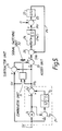
- An embodiment of this invention is described below with reference to FIG. 7. In FIG.7, the same symbols are used and detailed descriptions are omitted where components are the same as those in FIG.1. The following is mainly a description of those components which differ from prior art.
- That is to say, this system is provided with
subtractor unit 51 between the control target variable input terminal and the output terminal ofadder unit 1₄. At the same time,absolute value unit 52 is provided at the output side ofsubtractor unit 51. The design is that absolute value | δ | of deviation δ between control target variable SV and arithmetic target variable SVo is fetched. Also, membership function m( δ ) which takes a value from 0 to 1 in response to the absolute value is determined beforehand. Fuzzycoefficient setting unit 53 is provided which outputs membership function m( δ ) in response to the absolute value | δ | obtained fromabsolute value unit 52. Furthermore, apart frommultiplication unit 54 which multiplies output ofsubtractor unit 51 by membership function m( δ ),adder unit 55 which makes the target variable SVa for PI control by adding the multiplication value obtained bymultiplication unit 54 and arithmetic target variable SVo is also provided. - Therefore, when using the construction of the above embodiment, the deviation δ = SV - SVo between control target variable SV and arithmetic target variable SVo is obtained by
subtractor unit 51 for the variation of the step form of control target variable SV. Then, this deviation δ is transmitted toabsolute value unit 52 andmultiplication unit 54. After the absolute Value | δ | of deviation δ has been obtained byabsolute value unit 52, it is introduced to fuzzycoefficient setting unit 53. - In fuzzy
coefficient setting unit 53, when deviation δ = (SV - SVo) has become smaller than a value, for instance δ2, which does not interfere with the function of the originally imparted 2 degrees of freedom, membership function m( δ ) which exponentially takes thevalue 0 → 1 in the interval up to δ1 is outputted and transmitted tomultiplication unit 54 as this value δ2 of the deviation becomes smaller. As a result,multiplication unit 54 outputs multiplication variable m( δ ) · δ which becomes greater at a faster speed than the speed at which deviation signal δ (=SV - SVo), which is transmitted fromsubtractor unit 51, gradually becomes smaller. For this reason, fromadder unit 55 onwards, the response curve becomes steeper from a given time, that is to say from time ta, which is specified deviation δ2, and settles faster to control target variable SV, as shown at (b) in FIG. 8. - The fuzzy
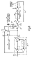
coefficient setting unit 53, etc, may be achieved by hardware using resistors, capacitors and semiconductors. They may also be achieved by means of software using a computer. - Next, the following is a description of another embodiment of this invention with reference to FIG. 9. In this case also, the same symbols are used and descriptions are omitted for parts which are the same as in FIG. 1. The following is mainly a description only of those parts which differ.
- That is to say, this embodiment is a design in which
absolute value unit 52 is omitted from FIG.7. Because of this, fuzzycoefficient setting unit 53′ individually sets membership functions m( δ ) in response to the sign of the deviation between control target variable SV and arithmetic target variable SVo. The membership functions m( δ ) for plus and minus are set so that they differ. - The following is a description of a system constructed in this way. Target variable SVa for PI control in this system is expressed as

- Here, when control target variable SV changes to step form, since the deviation δ of (SV -SVo) is greater and the relationship is

the membership function becomes m( δ ) = 0. Thus, from equation (8), SVa = SVo. That is to say,
Thus, SVa is determined only by the transfer function of targetvariable filter unit 21,and is then introduced intodeviation operation unit 13 as the target variable for PI control. Therefore, in this case, exactly the same response curve as in prior art can be obtained. - After this, when deviation δ obtained from
subtractor unit 51 becomes smaller than δ2, and the relationship becomes
the membership function from fuzzycoefficient setting unit 53′ becomes 0 < m( δ ) < 1. Thus, from equation (8),
and this SVa is transmitted todeviation operation unit 23 as the target variable for PI control. Therefore, in this case, at the time when deviation δ becomes smaller than deviation δ2 , the response curve becomes steeper than the prior art response curve, as shown at (b) in FIG. 8, and it approaches control target variable SV. - Moreover, when deviation δ obtained from
subtractor unit 51 has become smaller and the relationship has become
the membership function becomes m( δ ) = 1. Thus, from equation (8),
and control target value SV is transmitted todeviation operation unit 23 as it stands as the target variable for PI control. As a result, since the target variable for PI control is forcibly taken as control target variable SV at time tb when the deviation has becomes δ1 , it can be settled in a very much shorter time than in prior art. - Thus, when using the construction of the above embodiment, the design is that target variable SVa for PI control is forcibly and rapidly transferred to control target variable SV from the arithmetic target variable SVo of target
variable filter unit 21 using the membership function, when arithmetic target variable SVo of targetvariable filter unit 21 approaches control target variable SV, that is to say when the deviation between the two target variables becomes less than specified value δ2 . Therefore, the target variable follow-up time can be greatly reduced without any influence on the function of 2 degrees of freedom. Thus, the performance of this type of control device with 2 degrees of freedom can be greatly improved. Therefore, the provision of these systems throughout a plant can greatly contribute to improvement of the plant operating characteristics. - Incidentally, the above embodiment are designed to supply the multiplication variable of the output of
subtactor unit 51 and the membership function to adderunit 55. However, they may also be designed to eliminatemultiplication unit 54 and to output values equivalent to the multiplication variable from fuzzycoefficient setting units adder unit 55. Also, PI control operation has been described in the above embodiments. However, needless to say, this invention can also applied in the same way for PID control operation. - When using this invention as described above, a fuzzy combination type control system with 2 degrees of freedom can be provided which can greatly reduce the response time for variation of the target variable compared with the prior art, and thus contributes greatly to the improvement of performance.
Claims (13)
- A system for controlling a process system subject to an external disturbance by adjusting a process variable output by the process system to a given target variable comprising target variable filter means (21) for generating a computed target variable to perform a compensation control operation; deviation operation means (23) for computing a deviation between the process variable and the computed target variable inputted from the target variable filter means; and main control means (24) for performing at least proportional and integral control operations on the computed deviation between the process variable and the computed target variable inputted from the deviation operation means to suppress fluctation of the process variable produced by the external disturbance; characterised in target variable control means for changing the input into the deviation operation means from the computed target variable to the given target variable either at the moment when the deviation between the given target variable and the computed target variable computed by the target variable filter means is less than a predetermined value or gradually, at a predetermined speed rate, after the deviation between the given target variable and the computed target variable has become less than a predetermined value.
- The system of claim 1, characterised in that the target variable control means includes comparator means (11) for generating a switching signal when the deviation between the given target variable and the computed target variable is less than a predetermined value, and switching means (12) responsive to the switching signal for changing an input into the deviation operation means from the computed target variable to the given target variable.
- The system of claim 1, characterised in that the target variable control means includes comparator means (11) for generating a switching signal when the deviation between the given target variable and the computed target variable is less than a predetermined value, subtractor means (31) for holding the deviation, and switching means (32, 33) responsive to the switching signal for adding the deviation to the computed target variable.
- The system of claim 3, characterised in that the switching means includes adder means (33) for adding the deviation to the computed target value to supply the given target variable to the deviation operation means, and signal switching means (32) responsive to the switching signal for inputting the deviation to the adder means.
- The system of claim 4, characterised in that the switching means further includes first order lag element means (41) for smoothing the deviation before the deviation is input into the adder means.
- The system of claim 1, characterised in that the target variable control means includes subtractor means (51) for holding a deviation between the given target variable and the computed target variable, fuzzy coefficient generating means (52, 53, 54, 55 or 53′, 54, 55) for generating a fuzzy coefficient having a value between 1 and 0 according to the deviation, for generating a multiplication variable produced by multiplying the deviation by the fuzzy coefficient and for supplying the computed target variable and the multiplication variable to the deviation operation means.
- The system of claim 6, characterised in that the fuzzy coefficient generating means includes absolute value means (52) for converting the value of the deviation to its absolute value, fuzzy coefficient setting means (53) for generating a fuzzy coefficient value having a value between 1 and 0 according to the absolute value of the deviation, adder means (55) for supplying the computed target variable and the multiplication variable to the deviation operation means, and multiplication means (54) for generating a multiplication variable produced by multiplying the deviation by the fuzzy coefficient value.
- A method of controlling a process system subject to an external disturbance by adjusting according to a deviation output by a deviation operation means, a process variable output by the process system to a given target variable comprising the steps of generating a computed target variable to perform a compensation control operation; computing a deviation between the process variable and the computed target variable inputted into the deviation operation means; performing at least proportional and integral control operations on the computed deviation between the process variable and the computed target variable inputted from the deviation operation means to suppress fluctuation of the process variable produced by the external disturbance; characterised by changing the input into the deviation operation means from the computed target variable to the given target variable either at the moment when a deviation between the given target variable and the computed target variable is less than a predetermined value or gradually, at a predetermined speed rate after a deviation between the given target variable and the computed target variable has become less than a predetermined value.
- The method of claim 8, characterised in that the step of changing includes the step of generating a switching signal when the deviation between the given target variable and the computed target variable is less than a predetermined value, and the step of changing in response to the switching signal an input into the deviation operation means from the computed target variable to the given target variable.
- The method of claim 9, characterised in that the step of changing includes the step of generating a switching signal when the deviation between the given target variable and the computed target variable is less than a predetermined value, the step of holding the deviation, and the step of adding the deviation to the computed target variable to supply the given target variable to the deviation operation means.
- The method of claim 10, characterised in that the step of adding further includes the step of smoothing the deviation.
- The method of claim 8, characterised in that the step of changing includes the step of holding the deviation, the step of generating a fussy coefficient having a value between 1 and 0 according to the deviation, the step of generating a multiplication variable produced by multiplying the deviation by the fussy coefficient value, and the step of supplying the computed target variable and the multiplication variable to the deviation operation means.
- The method of claim 12, characterised in that the step of generating a fuzzy coefficient includes the step of converting the value of the deviation to its absolute value, the step of generating a fuzzy coefficient value having a value between 1 and 0 according to the absolute value of the deviation, the step of supplying the computed target variable and the multiplication variable to the deviation operation means, and the step of generating a multiplication variable produced by multiplying the deviation by the fuzzy coefficient value.
Applications Claiming Priority (4)
| Application Number | Priority Date | Filing Date | Title |
|---|---|---|---|
| JP237643/90 | 1990-09-07 | ||
| JP23764390A JP2809849B2 (en) | 1990-09-07 | 1990-09-07 | 2-DOF adjustment device |
| JP237642/90 | 1990-09-07 | ||
| JP23764290A JP2752240B2 (en) | 1990-09-07 | 1990-09-07 | Target value tracking speed responsive 2-DOF adjustment device |
Publications (3)
| Publication Number | Publication Date |
|---|---|
| EP0474492A2 EP0474492A2 (en) | 1992-03-11 |
| EP0474492A3 EP0474492A3 (en) | 1993-04-28 |
| EP0474492B1 true EP0474492B1 (en) | 1995-11-15 |
Family
ID=26533300
Family Applications (1)
| Application Number | Title | Priority Date | Filing Date |
|---|---|---|---|
| EP91308139A Expired - Lifetime EP0474492B1 (en) | 1990-09-07 | 1991-09-05 | Two degrees of freedom type control system |
Country Status (6)
| Country | Link |
|---|---|
| US (1) | US5245529A (en) |
| EP (1) | EP0474492B1 (en) |
| KR (1) | KR950009526B1 (en) |
| CN (1) | CN1045669C (en) |
| AU (1) | AU625714B2 (en) |
| DE (1) | DE69114623T2 (en) |
Families Citing this family (7)
| Publication number | Priority date | Publication date | Assignee | Title |
|---|---|---|---|---|
| JPH06274205A (en) * | 1993-03-22 | 1994-09-30 | Toshiba Corp | Gain adaptive control device |
| US5848535A (en) * | 1997-03-24 | 1998-12-15 | Gas Research Institute | Control system having a binomial setpoint filter |
| DE19734711C1 (en) * | 1997-08-11 | 1999-04-15 | Siemens Ag | Controllers with discrete-time, dynamic fuzzy control elements |
| JP2005509935A (en) * | 2001-07-24 | 2005-04-14 | コーニンクレッカ フィリップス エレクトロニクス エヌ ヴィ | How to transfer a signal from a manual signal generator |
| DE10226670B4 (en) * | 2002-06-14 | 2004-09-02 | Siemens Ag | Control device and procedure |
| CN106950835B (en) * | 2017-04-19 | 2020-03-17 | 上海交通大学 | Simple and robust two-degree-of-freedom proportional-integral control method |
| US11782402B2 (en) * | 2021-07-02 | 2023-10-10 | Mitsubishi Electric Research Laboratories, Inc. | Device for controlling a system with polynomial dynamics |
Family Cites Families (11)
| Publication number | Priority date | Publication date | Assignee | Title |
|---|---|---|---|---|
| US4539633A (en) * | 1982-06-16 | 1985-09-03 | Tokyo Shibaura Denki Kabushiki Kaisha | Digital PID process control apparatus |
| JPS6069702A (en) * | 1983-09-26 | 1985-04-20 | Toshiba Corp | Sampled value process controller |
| US4755924A (en) * | 1985-02-19 | 1988-07-05 | Kabushiki Kaisha Toshiba | Process controller having an adjustment system with two degrees of freedom |
| JPS6266301A (en) * | 1985-09-18 | 1987-03-25 | Yamatake Honeywell Co Ltd | Auto tuning controller |
| JPS6346503A (en) * | 1986-08-14 | 1988-02-27 | Yokogawa Electric Corp | Pid controller |
| JPS6346502A (en) * | 1986-08-14 | 1988-02-27 | Yokogawa Electric Corp | Pid controller |
| US4881160A (en) * | 1987-03-09 | 1989-11-14 | Yokogawa Electric Corporation | Self-tuning controller |
| JPH07104681B2 (en) * | 1988-03-18 | 1995-11-13 | 株式会社東芝 | Process control equipment |
| JPH0774961B2 (en) * | 1988-04-07 | 1995-08-09 | 株式会社日立製作所 | Auto tuning PID controller |
| JPH0298701A (en) * | 1988-10-05 | 1990-04-11 | Toshiba Corp | Controller |
| AU611839B1 (en) * | 1989-09-11 | 1991-06-20 | Kabushiki Kaisha Toshiba | Two degree of freedom controller |
-
1991
- 1991-09-05 EP EP91308139A patent/EP0474492B1/en not_active Expired - Lifetime
- 1991-09-05 DE DE69114623T patent/DE69114623T2/en not_active Expired - Fee Related
- 1991-09-06 AU AU83656/91A patent/AU625714B2/en not_active Ceased
- 1991-09-07 CN CN91109572A patent/CN1045669C/en not_active Expired - Fee Related
- 1991-09-07 KR KR1019910015624A patent/KR950009526B1/en not_active IP Right Cessation
- 1991-09-09 US US07/757,011 patent/US5245529A/en not_active Expired - Fee Related
Also Published As
| Publication number | Publication date |
|---|---|
| CN1045669C (en) | 1999-10-13 |
| KR920006824A (en) | 1992-04-28 |
| DE69114623T2 (en) | 1996-04-18 |
| AU625714B2 (en) | 1992-07-16 |
| KR950009526B1 (en) | 1995-08-23 |
| CN1060540A (en) | 1992-04-22 |
| AU8365691A (en) | 1992-03-19 |
| US5245529A (en) | 1993-09-14 |
| EP0474492A3 (en) | 1993-04-28 |
| DE69114623D1 (en) | 1995-12-21 |
| EP0474492A2 (en) | 1992-03-11 |
Similar Documents
| Publication | Publication Date | Title |
|---|---|---|
| Hauser | Learning control for a class of nonlinear systems | |
| Cao et al. | Analysis and design of fuzzy control systems using dynamic fuzzy-state space models | |
| US7805207B2 (en) | Method and apparatus for adaptive parallel proportional-integral-derivative controller | |
| US4663703A (en) | Predictive model reference adaptive controller | |
| JP3516232B2 (en) | Method and apparatus for implementing feedback control that optimally and automatically rejects disturbances | |
| Wright et al. | Nonminimum‐phase compensation for nonlinear processes | |
| US7080055B2 (en) | Backlash compensation with filtered prediction in discrete time nonlinear systems by dynamic inversion using neural networks | |
| EP0553356B1 (en) | Method and apparatus for prediction repetition control of servo motor | |
| EP0474492B1 (en) | Two degrees of freedom type control system | |
| EP0518651B1 (en) | Process control system | |
| Liu et al. | Observer-based composite adaptive dynamic terminal sliding-mode controller for nonlinear uncertain SISO systems | |
| US4887015A (en) | Position control system | |
| EP0709754B1 (en) | Prediction controller | |
| EP0037579B1 (en) | Adaptive-predictive control method and adaptive-predictive control system | |
| JP3107800B2 (en) | Control system | |
| Elnaggar et al. | New method for delay estimation | |
| JPS61109104A (en) | Pid controller | |
| JPH04256102A (en) | Model estimation controller | |
| Cao et al. | Model predictive control via piecewise constant output feedback for multirate sampled-data systems | |
| JP2915220B2 (en) | Process control equipment | |
| JPH04117501A (en) | Fuzzy combination type 2-freedom degree controller | |
| KR100198056B1 (en) | Feedback controlling device and method | |
| JP3256950B2 (en) | Optimal preview learning control device | |
| JPS5941004A (en) | Process control device | |
| JP2765797B2 (en) | Fuzzy temperature control system |
Legal Events
| Date | Code | Title | Description |
|---|---|---|---|
| PUAI | Public reference made under article 153(3) epc to a published international application that has entered the european phase |
Free format text: ORIGINAL CODE: 0009012 |
|
| 17P | Request for examination filed |
Effective date: 19910913 |
|
| AK | Designated contracting states |
Kind code of ref document: A2 Designated state(s): DE FR GB |
|
| PUAL | Search report despatched |
Free format text: ORIGINAL CODE: 0009013 |
|
| AK | Designated contracting states |
Kind code of ref document: A3 Designated state(s): DE FR GB |
|
| 17Q | First examination report despatched |
Effective date: 19950109 |
|
| GRAA | (expected) grant |
Free format text: ORIGINAL CODE: 0009210 |
|
| AK | Designated contracting states |
Kind code of ref document: B1 Designated state(s): DE FR GB |
|
| REF | Corresponds to: |
Ref document number: 69114623 Country of ref document: DE Date of ref document: 19951221 |
|
| ET | Fr: translation filed | ||
| PLBE | No opposition filed within time limit |
Free format text: ORIGINAL CODE: 0009261 |
|
| STAA | Information on the status of an ep patent application or granted ep patent |
Free format text: STATUS: NO OPPOSITION FILED WITHIN TIME LIMIT |
|
| 26N | No opposition filed | ||
| PGFP | Annual fee paid to national office [announced via postgrant information from national office to epo] |
Ref country code: GB Payment date: 19970827 Year of fee payment: 7 |
|
| PGFP | Annual fee paid to national office [announced via postgrant information from national office to epo] |
Ref country code: FR Payment date: 19970909 Year of fee payment: 7 |
|
| PGFP | Annual fee paid to national office [announced via postgrant information from national office to epo] |
Ref country code: DE Payment date: 19970912 Year of fee payment: 7 |
|
| PG25 | Lapsed in a contracting state [announced via postgrant information from national office to epo] |
Ref country code: GB Free format text: LAPSE BECAUSE OF NON-PAYMENT OF DUE FEES Effective date: 19980905 |
|
| GBPC | Gb: european patent ceased through non-payment of renewal fee |
Effective date: 19980905 |
|
| PG25 | Lapsed in a contracting state [announced via postgrant information from national office to epo] |
Ref country code: FR Free format text: LAPSE BECAUSE OF NON-PAYMENT OF DUE FEES Effective date: 19990531 |
|
| PG25 | Lapsed in a contracting state [announced via postgrant information from national office to epo] |
Ref country code: DE Free format text: LAPSE BECAUSE OF NON-PAYMENT OF DUE FEES Effective date: 19990701 |
|
| REG | Reference to a national code |
Ref country code: FR Ref legal event code: ST |