EP0474321A2 - Transportation system of a floated-carrier type - Google Patents
Transportation system of a floated-carrier type Download PDFInfo
- Publication number
- EP0474321A2 EP0474321A2 EP91202887A EP91202887A EP0474321A2 EP 0474321 A2 EP0474321 A2 EP 0474321A2 EP 91202887 A EP91202887 A EP 91202887A EP 91202887 A EP91202887 A EP 91202887A EP 0474321 A2 EP0474321 A2 EP 0474321A2
- Authority
- EP
- European Patent Office
- Prior art keywords
- rail
- carrier
- coupling
- rails
- transportation system
- Prior art date
- Legal status (The legal status is an assumption and is not a legal conclusion. Google has not performed a legal analysis and makes no representation as to the accuracy of the status listed.)
- Granted
Links
Images


Classifications
-
- B—PERFORMING OPERATIONS; TRANSPORTING
- B60—VEHICLES IN GENERAL
- B60L—PROPULSION OF ELECTRICALLY-PROPELLED VEHICLES; SUPPLYING ELECTRIC POWER FOR AUXILIARY EQUIPMENT OF ELECTRICALLY-PROPELLED VEHICLES; ELECTRODYNAMIC BRAKE SYSTEMS FOR VEHICLES IN GENERAL; MAGNETIC SUSPENSION OR LEVITATION FOR VEHICLES; MONITORING OPERATING VARIABLES OF ELECTRICALLY-PROPELLED VEHICLES; ELECTRIC SAFETY DEVICES FOR ELECTRICALLY-PROPELLED VEHICLES
- B60L13/00—Electric propulsion for monorail vehicles, suspension vehicles or rack railways; Magnetic suspension or levitation for vehicles
- B60L13/03—Electric propulsion by linear motors
-
- B—PERFORMING OPERATIONS; TRANSPORTING
- B60—VEHICLES IN GENERAL
- B60L—PROPULSION OF ELECTRICALLY-PROPELLED VEHICLES; SUPPLYING ELECTRIC POWER FOR AUXILIARY EQUIPMENT OF ELECTRICALLY-PROPELLED VEHICLES; ELECTRODYNAMIC BRAKE SYSTEMS FOR VEHICLES IN GENERAL; MAGNETIC SUSPENSION OR LEVITATION FOR VEHICLES; MONITORING OPERATING VARIABLES OF ELECTRICALLY-PROPELLED VEHICLES; ELECTRIC SAFETY DEVICES FOR ELECTRICALLY-PROPELLED VEHICLES
- B60L13/00—Electric propulsion for monorail vehicles, suspension vehicles or rack railways; Magnetic suspension or levitation for vehicles
- B60L13/04—Magnetic suspension or levitation for vehicles
- B60L13/06—Means to sense or control vehicle position or attitude with respect to railway
- B60L13/08—Means to sense or control vehicle position or attitude with respect to railway for the lateral position
-
- B—PERFORMING OPERATIONS; TRANSPORTING
- B65—CONVEYING; PACKING; STORING; HANDLING THIN OR FILAMENTARY MATERIAL
- B65G—TRANSPORT OR STORAGE DEVICES, e.g. CONVEYORS FOR LOADING OR TIPPING, SHOP CONVEYOR SYSTEMS OR PNEUMATIC TUBE CONVEYORS
- B65G54/00—Non-mechanical conveyors not otherwise provided for
- B65G54/02—Non-mechanical conveyors not otherwise provided for electrostatic, electric, or magnetic
-
- E—FIXED CONSTRUCTIONS
- E01—CONSTRUCTION OF ROADS, RAILWAYS, OR BRIDGES
- E01B—PERMANENT WAY; PERMANENT-WAY TOOLS; MACHINES FOR MAKING RAILWAYS OF ALL KINDS
- E01B25/00—Tracks for special kinds of railways
- E01B25/30—Tracks for magnetic suspension or levitation vehicles
-
- B—PERFORMING OPERATIONS; TRANSPORTING
- B60—VEHICLES IN GENERAL
- B60L—PROPULSION OF ELECTRICALLY-PROPELLED VEHICLES; SUPPLYING ELECTRIC POWER FOR AUXILIARY EQUIPMENT OF ELECTRICALLY-PROPELLED VEHICLES; ELECTRODYNAMIC BRAKE SYSTEMS FOR VEHICLES IN GENERAL; MAGNETIC SUSPENSION OR LEVITATION FOR VEHICLES; MONITORING OPERATING VARIABLES OF ELECTRICALLY-PROPELLED VEHICLES; ELECTRIC SAFETY DEVICES FOR ELECTRICALLY-PROPELLED VEHICLES
- B60L2200/00—Type of vehicles
- B60L2200/26—Rail vehicles
-
- F—MECHANICAL ENGINEERING; LIGHTING; HEATING; WEAPONS; BLASTING
- F16—ENGINEERING ELEMENTS AND UNITS; GENERAL MEASURES FOR PRODUCING AND MAINTAINING EFFECTIVE FUNCTIONING OF MACHINES OR INSTALLATIONS; THERMAL INSULATION IN GENERAL
- F16C—SHAFTS; FLEXIBLE SHAFTS; ELEMENTS OR CRANKSHAFT MECHANISMS; ROTARY BODIES OTHER THAN GEARING ELEMENTS; BEARINGS
- F16C32/00—Bearings not otherwise provided for
- F16C32/04—Bearings not otherwise provided for using magnetic or electric supporting means
- F16C32/0406—Magnetic bearings
- F16C32/044—Active magnetic bearings
- F16C32/0472—Active magnetic bearings for linear movement
Definitions
- the present invention relates to a transportation system of a floated-carrier type, and more particularly, to a transportation system, in which a carrier is suspended from a guide rail, in a non-contact manner, and is propelled along the guide rail.
- a track supporting a guide rail is installed in correspondence with a path along which the carrier travels, in a factory.
- a stator for linear induction motors for propelling the carrier are arranged on the track at predetermined intervals.
- the stator is provided with an inverter which energizes the stator according to travel instruction supplied from a controller (described later).
- a reaction plate for linear induction motor is mounted on the carrier.
- the carrier is received accelerating or decelerating force from the stator, in such a manner that the carrier travels along the guide rail of the track.
- Various sensors are provided at predetermined positions of the track.
- Various controllers for controlling the traveling of the carrier based on signals from the sensors are provided to this system.
- the sensors detect a current traveling position of the carrier, a traveling speed of the carrier, the type of carrier, and the like. These detection signals are supplied to the controllers and processed thereby. Carrier travel instructions are supplied from the controllers to the inverter provided on the stator, thereby controlling the traveling of the carrier.
- a transportation system of a floated-carrier type for transporting a cargo between predetermined positions comprising: a plurality of track units which are assembled each other, each of the track units including a guide rail formed of a ferromagnetic material and extending longitudinally by a predetermined length, support means for supporting the guide rail, an electrical wire extending longitudinally by a predetermined length, and a pair of connectors provided to both ends of the electrical wire; a carrier for carrying the cargo, the carrier including a magnetic unit for suspending the carrier from the guide rail in a non-contact manner, the magnetic unit including an electromagnet arranged to have an air gap with respect to the guide rail, and a permanent magnet magnetically coupled to the electromagnet, the guide rail, the air gap, the electromagnet, and the permanent magnet defining a magnetic circuit, the permanent magnet providing magnetic energy, with which the carrier can be kept suspending against the weight thereof and the load thereon, the electromagnet adapted to be excited so as to maintain the gap clearance,
- each track unit comprises minimum and necessary elements required for traveling the carrier.
- connection of electrical wires necessary for this system is completed. For this reason, an operation for mounting the electrical wires in the track can be omitted, and installation of the track can be facilitated.
- the travel path of the carrier when the travel path of the carrier is to be modified, a combination of track units can be freely changed, thus realizing various travel paths of the carrier. For this reason, the travel path can be easily modified.
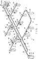
- Fig. 1 shows track assembly 10 of a transportation system of a floated-carrier type according to the present invention.
- carrier 21 is suspended from track assembly 10 in a non-contact manner, and is propelled along the track assembly.
- track assembly 10 is constituted by annular main line 11, U-shaped branch line 12 extending transversally from main line 11, and linear branch line 13 extending transversally from main line 11.
- Main line 11 is connected to first station 91 for loading a cargo transported from a warehouse or the like or unloading the cargo from carrier 21 and transporting the cargo to the warehouse or the like.
- Main line 11 is also connected to second station 92 for maintaining and inspecting carrier 11.
- Third station 93 for unloading or loading a cargo from or onto carrier 21 is provided beside branch lines 12 and 13.
- Each of stations 91 to 93 comprises loader 94 for loading a cargo onto carrier 21 and lifter 95 for lifting the cargo between loader 94 and a predetermined position. (These stations are described in INTERNATIONAL CONFERENCE ON MAGLEV AND LINER DRIVES. May, 1987.)
- Track assembly 10 is constituted by selectively combining a plurality of track units. In this transportation system, five types of track units are combined.
- First track unit 16 is a straight track unit for propelling carrier 21 along a straight track.
- Second track unit 17 is a curved track unit for propelling carrier 21 along a curved track.
- Third track unit 18 is a rotary branch unit in which two tracks are perpendicularly branched, and which is used for rotating carrier 21 so as to guide it from one track to the other track.
- Fourth track unit 19 is an orthogonal branch unit in which two tracks are perpendicularly branched and which is used for guiding carrier 21 from one track to the other track without rotating carrier 21.
- Fifth track unit 20 is a curved branch unit in which a curved track is branched from a straight track.
- First track unit 16 comprises a pair of support members 31 each of which is formed of a non-ferromagnetic material, extends longitudinally by a predetermined length, and has an E-shaped section.
- Each support member 31 has vertical base member 32.
- Upper flange 33, middle flange 34, and lower flange 35 extend from each base member 32.
- a pair of guide rails 36 are mounted on lower surfaces of middle flanges 34.
- Each guide rail 36 is formed of a ferromagnetic material, and extends longitudinally by a predetermined length.
- the pair of support members 31 are coupled by a plurality of coupling members 37.
- Stator 40 for a linear induction motor constituting propelling means is provided to first track unit 16. Stator 40 is supported on the lower surfaces of two coupling members 37. Stator 40 is arranged to face reaction plate 58 (to be described later).
- First or position sensor 41 for detecting if carrier 21 passes a predetermined position, and second or speed sensor 42 for detecting a speed when carrier 21 passes the predetermined position, are mounted on the side surface of one base member 32.
- Third or identification sensor 43 for identifying the type of carrier 21 is mounted on the side surface of the other base member 32.
- Inverter 44 and linear motor controller 45 are mounted on the upper surface of one end coupling member 37. Inverter 44 supplies three-phase AC power to stator 40. Linear motor controller 45 controls the three-phase AC power supplied from inverter 44 to stator 40 in accordance with detection signals from first and second sensors 41 and 42. Thus, carrier 21 is accelerated, decelerated, or stopped.
- electrical wire 46 is mounted on the side surface of each base member 32.
- Electrical wire 46 includes a power wire, connected to, e.g., inverter 44 and stator 40, for supplying power thereto, and a signal wire connected to first to third sensors 41 to 43, inverter 44, and linear motor controller 45, for transmitting electrical signals.
- a pair of connectors 47 are provided to both ends of electrical wire 46.
- Carrier 21 will be described hereinafter.
- Carrier 21 comprises flat supporting plate 51 which is located below guide rail 36.
- Four magnetic units 50 are arranged at four corners of supporting plate 51. Magnetic units 50 cause carrier 21 to float from guide rails 36 in a non-contact manner.
- magnetic units 50 are each provided with yokes 51 and 52, facing guide rail 36. Conducting wires are wound around yokes 51 and 52, thus forming coils 53 and 54.
- Air gap P is defined between the top face of each yoke and the lower surface of rail 36.
- Permanent magnet 55 is used to couple yokes 51 and 52 magnetically.
- magnet 55, yokes 51 and 52, gap P, and rail 36 constitute a magnetic circuit.
- Each magnetic unit is further provided with gap sensor 56 for detecting the clearance of gap P.
- Carrier 21 is suspended floating from guide rails 36, in a non-contact manner, by means of a magnetic attractive force acting between magnetic units 50 and guide rail 36.
- units 50 are controlled by zero-power control device, so that the minimum necessary circuit current is supplied to coils 53 and 54 when carrier 21 is made to float.
- four permanent magnets 55 always generate an attractive force equal to the total weight of carrier 21 itself and the load.
- coils 53 and 54 are excited, so as to maintain the air gap clearance at which the attractive force between permanent magnets 55 and rail 36 balances with the total weight of the carrier itself and the load. Coils 53 and 54 serve to subordinately cause carrier 21 to float.
- the current fed to coils 53 and 54 is controlled so that gap P is adjusted to a distance such that the total attractive force between permanent magnets 55 and guide rails 36 balances the total weight of carrier 21 and the load.
- clearance of gap P is adjusted to a value such that carrier 21 is caused to float by means of the magnetic energy of permanent magnet 55 only, despite the existence of disturbances.
- Reaction plate 58 constituting a propelling means is mounted at the center of the upper surface of supporting plate 51. Reaction plate 58 faces stator 40. If stator 40 is supplied with current, a traveling magnetic field is generated in stator 40, so that the current is induced to reaction plate 58. Through an interaction between the traveling field and the induced current, reaction plate 58 is subjected to thrust from stator 40, and a propelling force along the guide rail is applied to the carrier.
- hook 61 extends downward from the side edge of supporting plate 51.
- Carrier box 62 for storing a cargo is mounted on the distal end portion of hook 61.
- Wheels 64 are provided to the side edges of supporting plate 51. Wheels 64 are in contact with upper surfaces of corresponding lower flanges 35 of support members 31 when magnetic units 50 do not generate a magnetic attraction force. Wheels 66 are also provided above wheels 64. Wheels 66 are in contact with the lower surfaces of middle flanges 34 of support members 31 when carrier 21 is lifted to its uppermost position.
- Bar code 67 is provided to the side surface of carrier 21. Bar code 67 is located to face first to third sensors 41 to 43. First to third sensors 41 to 43 read bar code 57, so as to detect if the carrier passes the predetermined position, a speed when the carrier passes the predetermined position, and the type of carrier.
- Second track unit or curved track unit 17 is substantially the same as first track unit 16 except that its track is curved.
- Third track unit or rotary branch unit 18 comprises a coupling section for coupling the guide rail of main line 11 and guide rails of branch lines 12 and 13.
- the coupling section is provided with a transfer means for guiding the carrier from main line 11 to branch line 12. Therefore, when carrier 21 receives an instruction for transferring the carrier from the main line to the branch line, the carrier, having so far been running along the main line, is stopped at the coupling section, then rotated, then stopped from rotating when the carrier faces the branch line, and then transferred from the coupling section to the second rail section, all in a non-contact manner.
- This third track unit is disclosed in detail in EPC Appl. Ser. No.
- Fourth track unit or orthogonal branch unit 19 comprises the coupling section and the transfer means as in the third track unit. For this reason, when carrier 21 receives an instruction for transferring the carrier from branch line 13 to branch line 70, the carrier, having so far been running along branch line 13, is stopped at the coupling section, and is then transferred from the coupling section to the branch line 70, all in a non-contact manner. Unlike third track unit 18, in fourth track unit 19, the carrier is not rotated when it is stopped at the coupling section. For this reason, on branch line 70, carrier 21 travels in a transverse direction thereof. Third station 93 is connected to branch line 70 extending from fourth track unit 19.
- third station 93 loads/unloads a cargo onto/from carrier 21.
- the subsequent carrier can pass by the stopping carrier.
- a travel time of the carrier can be shortened, and a transportation time of the cargo in this transportation system can be shortened.
- Fourth track unit 19 may be mounted on main line 11.
- the carrier temporarily stands by on the branch line extending from fourth track unit 19.
- the fourth track unit is disclosed in detail in EPC Appl. Ser. No. 87302686,8 filed previously by the applicant hereof,
- Fifth track unit or curved branch unit 20 will be described later in detail.
- Each track unit comprises elements necessary for traveling the carrier.
- connection of electrical wires necessary for this system can be completed. For this reason, a mounting operation of electrical wires in the track can be omitted, thus facilitating installation of the track.
- the travel path of the carrier when the travel path of the carrier is modified, a combination of track units are freely changed, so that various travel paths of the carrier can be realized. Thus, the travel path can be easily modified. Furthermore, when one track unit is malfunctioned, the track unit can be replaced with a new one. For this reason, maintenance and inspection of the system can be facilitated.
- a charging power source for charging the battery mounted on carrier 21 is provided to this system.
- Carrier 21 comprises a first terminal connected to the battery.
- branch line 70 is provided with a second terminal connected to the charging power source.
- the charging power source supplies power to the battery via the first and second terminals. Since the battery is charged while the cargo is loaded/unloaded onto/from the carrier, the loading/unloading time can be effectively utilized.
- the charging power source is disclosed in detail in EPC Appl. Ser. No.
- supervisory transportation controller 81 In order to control travel of the carrier, supervisory transportation controller 81 and a plurality of local controllers 82 and 83 are provided to this transportation system, as shown in Fig. 5.
- Supervisory transportation controller 81 is connected to host computer for production control 80.
- Host computer 80 manages production control for the entire plant, and creates instruction regarding transportation jobs for supervisory transportation controller 81.
- Supervisory transportation controller 81 manages and monitors the overall transportation system and distributes carriers 21 in an optimum timing and sequence to perform the transportation job instructed by a host computer.
- Local controller 82 performs traffic control of the carriers traveling along main line 11, and supplies an instruction for controlling first station 91 to station controller 84.
- Local controller 83 performs traffic control of the carriers traveling along branch lines 12 and 13, and supplies an instruction for controlling third station 93 to station controller 85.
- Station controllers 84 and 85 control loader 94 and lifter 95.
- Each station is provided with terminal 86.
- An operator can operate terminal 86 to create the transportation job.
- the speed and position of the carrier are detected by speed sensor 41 and position sensor 42, and the detection signals are supplied to linear motor controller 45.
- Identification sensor 43 identifies the type of carrier, and the detection signal is supplied to local controller 83.
- an auxiliary electrical power source is provided to the system so that power is kept supplied to the transportation system without cutting off power supply to the transportation system.
- the carrier travels while being suspended from the guide rails in a non-contact manner. For this reason, during traveling of the carrier, neither noise, vibration, nor dust are generated.
- the carrier and the guide rails are not in mechanical contact with each other.
- no impact force is applied to the carrier.
- the cargo receives no impact force.
- the carrier propelled by the linear motor while being suspended from the guide rails in a non-contact manner. For this reason, the carrier can be accelerated and decelerated immediately.
- the track preferably has a main line coupling principal points, and a large number of branch lines branching from the main line and coupled to subpoints. For this reason, a large number of branch units for transferring the carrier from the main line to the branch line and vice versa are necessary. That is, if a large number of branch units are not provided to the track, a large number of carriers cause traffic jam, and traffic control may become impossible.
- U.S. Pat. No. 4,109,508 describes a transportation system, which is provided with a rail-switching device at a diverging section, where branch lines diverge from main lines.
- the switching device When the switching device is operated mechanically, the main lines are disconnected from one another, and are connected to branch lines, so that a carrier can be transferred from the main lines to the branch lines.
- no rail switching device is provided, and main and branch lines are connected directly at a diverging section.
- a guide plate is provided at the diverging section, whereby the rollers of a carrier are guided from the diverging section to the branch lines. As the rollers slide along the guide plate, the carrier is transferred from the main lines to the branch lines.
- the branch unit for transferring the carrier, from the main lines to the branch lines requires a mechanical switching device. Therefore, the branch unit is increased in size, thereby reducing the available space in the factory. Moreover, the switching device is operated mechanically, and especially in the system stated in Japanese Patent Disclosure No. 50-150112, the rollers of the carrier are in contact with the guide plate while the carrier is being transferred. As a result, noise is produced by the transfer apparatus.
- the present inventors thus proposed third track unit or rotary branch unit 18 and fourth track unit or orthogonal branch unit 19 described above.
- a carrier is not in contact with the guide rails, and is transferred from one line to another line without producing noise.
- the size of the branch unit can be reduced.
- a carrier is temporarily stopped at the branch unit, and thereafter, is transferred from one line to another line. For this reason, a relatively long period of time is required in order to transfer the carrier from one line to another line.
- the carrier can reach its destination only after a long period of time.
- the present inventors proposed fifth track unit or curved branch unit 20 in which a carrier is transferred from one line to another line without being stopped at the branch unit.
- fifth track unit or curved branch unit 20 The arrangement of fifth track unit or curved branch unit 20 will be described.
- guide rails of track units adjacent to branch unit 20 are defined as first rails 101, second rails 102, and third rails 103.
- First and second rails 101 and 102 are arranged along an identical straight line, and third rails 103 intersect first and second rails 101 and 102.
- the guide rails of this branch unit comprise coupling section 104 for coupling first to third rails 101 to 103.
- Coupling section 104 comprises first coupling rails 105 and 106, second coupling rails 107 and 108, and third coupling rails 109 and 110.
- One end of each of first to third coupling rails 105 to 110 is connected to corresponding one of first to third rails 101 to 103.
- each of first coupling rails 105 and 106 is coupled to the other end of corresponding one of second and third coupling rails 107 to 110.
- forked rail joining sections 111 and 112 at which these coupling rails are joined to each other are defined.
- Each coupling rail is formed of a ferromagnetic material.
- First and second coupling rails 105 to 108 are linearly formed.
- Third coupling rails 109 and 110 have a predetermined radius of curvature, and are formed to have a curved shape.
- Third coupling rails 109 and 110 intersect the first coupling rails at an obtuse angle.
- An interval between a pair of coupling rails is the same as that between each pair of first to third rails 101 to 103, and is also the same as that between a pair of magnetic units 50.
- stator 116 of the linear induction motor is mounted on support members (not shown).
- Stator 116 is located to face reaction plate 58 of the carrier.
- Stator 116 and reaction plate 58 constitute a means for transferring the carrier from one rail pair to another rail pair.
- the carrier is suspended from the coupling rails in a non-contact manner by an electromagnetic attractive force between magnetic unit 50 and each coupling rail.
- magnetic unit 50 may be subjected to zero-power control described above.
- the carrier is transferred from the first rails to second or third rails (former case), and is transferred from the second or third rails to the first rails (latter case).
- the carrier coasting by receiving a predetermined propelling force from stator 40, enters from first rails 101 to first coupling rails 105 and 106.
- the carrier travels along the first coupling rails by the predetermined propelling force without being interfered.
- stator 116 biases reaction plate 58 in a direction indicated by arrow D
- the carrier is guided from first coupling rails 105 and 106 to second coupling rails 107 and 108. Thereafter, the carrier keeps traveling by the predetermined propelling force and is guided to second rails 102.
- stator 116 biases reaction plate 58 in a direction indicated by arrow E
- the carrier is guided from the first coupling rails 105 and 106 to third coupling rails 109 and 110. Thereafter, the carrier keeps traveling by the predetermined propelling force and is guided to third rails 103. Therefore, the carrier is transferred to predetermined rails while being suspended from the coupling rails in a non-contact manner without being stopped at the coupling rails.
- First coupling rails 105 and 106 are arranged along the same lines as second coupling rails 107 and 108, and obliquely intersect third coupling rails 109 and 110. In the latter case, the carrier need not receive a transfer force in the direction indicated by arrow D or E, and is automatically guided from the second or third coupling rails to the first coupling rails.
- first to third coupling rails are formed to have a planar shape
- the carrier may often fail to reliably transfer from first rails 101 to third rails 103. The reason will be explained below.
- pairs of first and second ridges 131 to 136 are formed at two sides of each coupling rail.
- First and second ridges 131 and 132 are formed of a ferromagnetic material, and face yokes 51 and 52 of magnetic units 50. More specifically, the width of each of first and second ridges 131 to 136 is substantially the same as that of each of yokes 51 and 52 in the transverse direction of the coupling rail.
- Each ridge is integrally formed on the coupling rail.
- yokes 51 and 52 are moved from the first coupling rail to the third coupling rail along ridges 131 and 132, and are not swung in the transverse direction of the rail. For this reason, the magnetic circuits formed by magnetic units 50 and the coupling rails are not disabled at forked rail joining section 111.
- the carrier can be reliably transferred from first rails 101 to second rails 103.
- fifth track unit or curved branch unit 20 has a shorter transfer time than third track unit or rotary branch unit 18, and the like. A time required until the carrier reaches the destination can be shortened.
- the carrier is transferred in a non-contact manner from the coupling rail. Therefore, no noise is generated. Furthermore, since the transfer means comprises the linear induction motor, the branch unit can be rendered compact. Therefore, a large number of branch units can be provided in a small space in a factory. Traffic control of a large number of carriers can be allowed, and a travel time of each carrier can be shortened.
- ridge intersection 140 at which first ridge 133 of the first coupling rail and second ridge 136 of the third coupling rail intersect each other is formed at each of rail joining sections 111 and 112.
- Figs. 12 and 13 show the section of ridge intersection 140.
- Fig. 12 shows a case wherein magnetic unit 50 is moved toward second coupling rails 107 and 108.
- Fig. 13 shows a case wherein magnetic unit 50 is moved toward third coupling rails 109 and 110.
- two ridges 133 and 136 intersect each other.
- the width of ridge intersection 140 is larger than that of yokes 51 and 52.
- ridge intersection 140 has region C1 which does not face yoke 52.
- region C1 Since the magnetic resistance of region C1 is smaller than the opposite side of ridge intersection 140 region C1, magnetic flux leakage from yoke 52 is flowed in region C1. For this reason, a force for attracting yoke 52 toward region C1 is applied to yoke 52. As a result, yoke 52 is swung.
- ferromagnetic projection 141 is provided to the side surface of each ridge intersection 140.
- yoke 52 receives attractive forces from both region C1 and projection 141. Since the two attractive forces are balanced, yoke 52 can be prevented from being attracted toward only region C1. As a result, swinging motion of yoke 52 can be prevented.
- ridge intersection 140 has region C2 which does not face yoke 51.
- Ferromagnetic projection 142 is provided to the side surface of ridge intersection 140.
- yoke 51 can be prevented from being attracted toward region C2, and can also be prevented from being swung.
- Projection 141 and 142 may be integrally formed on the ridge intersection.
- coupling section 104 has rail intersection 137 at which one second coupling rail 107 and one third coupling rail 110 intersect each other.
- Rail intersection 137 has a plurality of ridge intersections 139 at which first and second ridges 133 and 134 of second coupling rail 107 and first and second ridges 135 and 136 of third coupling rail 110 intersect each other.
- Projections 141 and 142 are provided to the side surface of ridge intersection 139.
- a control apparatus of branch unit 20 will be described hereinafter.
- photo sensor 145 is provided at an end portion of first coupling rail 106 near first rail 101.
- Photo sensor 146 is provided to an end portion of second coupling rail 107 near rail joining section 111.
- These photosensors 145 and 146 emit light toward reaction plate 58 of the carrier, and detect light reflected by plate 58.
- Sensor 145 detects whether or not the carrier enters first coupling rails 105 and 106, and generates a detection signal. More specifically, sensor 145 detects a timing when transfer of the carrier from first rails 101 to second or third rails 102 or 103 is started.
- Sensor 146 detects whether nor not the carrier enters second and third coupling rails 107 to 109, and generates a detection signal. More specifically, sensor 146 detects a timing when transfer of the carrier from first rails 101 to second or third rails 102 or 103 is finished.
- three-phase AC power source 148 is connected to stator 116 through inverter 149.
- the detection signals from sensors 145 and 146 are supplied to microcomputer 147.
- Microcomputer 147 also receives an instruction, supplied from an external apparatus e.g., linear motor controller 45, for transferring the carrier to a predetermined rail, and an instruction for stopping microcomputer 147.
- Microcomputer 147 determines the output frequency of inverter 149 and a propagating direction of a moving magnetic field generated in stator 116 based on these signals and instructions.
- magnetic unit 50 comprises gap sensor 56 for detecting gap P between yokes 53 and 54 and the guide rail.
- grooves 151 are formed in coupling rails 105 to 110 between pairs of ridges 131 to 136. For this reason, gap sensor 56 cannot accurately detect the gap between ridges 131 to 136 and yokes 51 and 52.
- non-magnetic member 152 is stored in each groove 151.
- the top face of non-magnetic member 152 is located on the identical plane to the top face of the ridge. Therefore, gap sensor 56 emits light toward the top face of non-magnetic member 152, and detects light reflected by the top face.
- sensors 145 and 146 are always operated. More specifically, when the carrier is not located at coupling section 104, the flow is looped in steps 102, 104, and 121.
- step 106 It is checked in step 106 whether the carrier is transferred to second or third rails 102 or 103. If the carrier is transferred to third rails 103, inverter 149 receives an instruction of a moving magnetic field in a direction indicated by arrow E and a predetermined frequency instruction in step 108. Then, the carrier traveling along the first coupling rails receives a transfer force toward the third coupling rails, and transfer of the carrier is started.
- step 109 When the carrier is transferred by a predetermined distance, sensor 145 is turned off in step 109. If the carrier is further transferred by the predetermined distance, sensor 146 is turned on in step 110. Thereafter, when the carrier has reached a position shown in Fig. 15, sensor 146 is turned off in step 111. Thus, transfer of the carrier from first rails 101 to third rails 103 is ended. Flow returns to step 101, so that inverter 149 receives a zero-frequency instruction and the energization of stator 116 is stopped. The carrier keeps traveling along third rails 103. Until subsequent carrier reaches first coupling rails 105 to 110, the flow is looped in steps 102, 104, and 121.
- inverter 149 receives an instruction of a moving magnetic field in a direction indicated by arrow D and a predetermined frequency instruction in step 107. Other operations are the same as those when the carrier is transferred to third rails 103. When the carrier has reached a position shown in Fig. 16, energization of stator 116 is stopped.
- a first microcomputer stop request which is supplied to prevent stator 116 from being energized at, for instance, trial traveling, is detected in steps 121 and 132, the flow jumps to an end. If a second microcomputer stop request, which is supplied to immediately stop the energization of stator 116 in emergency, is detected in steps 112, 141 and 152, the flow advances to step 113, a zero-frequency instruction is supplied to inverter 149, and the energization of stator 116 is stopped.
- each coupling rail As described above, a pair of ridges facing a pair of yokes are formed on each coupling rail. For this reason, magnetic flux leakage of each yoke is concentrated on only the ridge, and is not biased to other portions. Thus, a force for preventing the yoke from being shifted toward the transverse direction of the rail can be generated. The yoke is moved along the ridge, and swinging motion of the yoke can be prevented. Therefore, the magnetic circuit between the magnetic unit and the coupling rail cannot be disabled. The carrier can be reliably transferred from one line to another line, and cannot be dropped.
- fifth track unit or curved branch unit 20 has a shorter transfer time than third track unit or rotary branch unit 18. Therefore, a time required until the carrier reaches the destination can be shortened.
- the carrier is transferred in a non-contact manner, and hence, no noise is generated. Since the transfer means comprises the linear induction motor, the branch unit can be rendered compact. A large number of branch units can be provided to the track even in a small space in a factory. A large number of carriers can thus be subjected to traffic control, and a travel time of each carrier can be shortened.
- each second coupling rail 102 is linearly formed.
- second coupling rail 102 may be formed to have a curved shape.
- coupling section 104 may be coupled to four track units.
- the carrier can be transferred from first rails 101 to fourth coupling rails 161 and then fourth rails 162 by the same transfer means of above embodiment.
- Fig. 20 shows a modification of the coupling rail.
- Two grooves 170, 171 are formed on each coupling rail 105 to 110, thus defining three ridges 131 to 136, and 173.
- Ridges 131 to 136, together with yoke 51, 52, constitute magnetic circuits.
- Gap sensor 56 emits light toward the top face of ridge 173, so that the gap clearance between ridges 131 to 136 and yokes 51 and 52 is measured.
- manufacture of the coupling rail may be facilitated and non-magnetic member 152 may be omitted.
- the branch unit may alternatively be designed so as to transfer carrier 21 by utilizing air pressure.
- air nozzles 163 may be arranged so that they can blow air against carrier 21, thereby transferring the carrier from first coupling rail to second or third coupling rail.
- the number of yokes is not limited to two but may be three or more. If three or more yokes are arranged, each coupling rail need only have ridges corresponding in number to the yokes.
- the guide rail includes a pair of guide rails.
- the guide rail used may be one, or three, or more, in number.
- the magnetic unit may be constructed so that the carrier is caused to float by means of the magnetic force of the coils only, without using the permanent magnet.
Landscapes
- Engineering & Computer Science (AREA)
- Mechanical Engineering (AREA)
- Physics & Mathematics (AREA)
- Electromagnetism (AREA)
- Power Engineering (AREA)
- Transportation (AREA)
- Architecture (AREA)
- Civil Engineering (AREA)
- Structural Engineering (AREA)
- Control Of Vehicles With Linear Motors And Vehicles That Are Magnetically Levitated (AREA)
- Non-Mechanical Conveyors (AREA)
Abstract
Description
- The present invention relates to a transportation system of a floated-carrier type, and more particularly, to a transportation system, in which a carrier is suspended from a guide rail, in a non-contact manner, and is propelled along the guide rail.
- To increase office or factory automation, transportation systems have recently been installed in some buildings. Such systems are used to transport slips, documents, cash, samples, or the like, between a plurality of locations in the buildings.
- In order to avoid spoiling the environment of the offices or factories, transportation systems of this type are expected not to produce dust or high levels of noise. Thus, in EPC Appl. Ser. No. 85105028.6 filed previously by the applicant hereof, a carrier is kept suspending from a guide rail, in a non-contact manner, by means of an electromagnetic attractive force acting between the carrier and the guide rail, when the carrier is propelled along the guide rail.
- In this transportation system, a track supporting a guide rail is installed in correspondence with a path along which the carrier travels, in a factory. A stator for linear induction motors for propelling the carrier are arranged on the track at predetermined intervals. The stator is provided with an inverter which energizes the stator according to travel instruction supplied from a controller (described later). A reaction plate for linear induction motor is mounted on the carrier. Thus, the carrier is received accelerating or decelerating force from the stator, in such a manner that the carrier travels along the guide rail of the track. Various sensors are provided at predetermined positions of the track. Various controllers for controlling the traveling of the carrier based on signals from the sensors are provided to this system. Therefore, the sensors detect a current traveling position of the carrier, a traveling speed of the carrier, the type of carrier, and the like. These detection signals are supplied to the controllers and processed thereby. Carrier travel instructions are supplied from the controllers to the inverter provided on the stator, thereby controlling the traveling of the carrier.
- In order to connect the various sensors and the various controllers, a number of signal wires through which electrical signals propagate are necessary. In addition, power wires for supplying power to the stator for the linear induction motors are also necessary. These signal wires and power wires are disposed along the track. A cumbersome operation is required to mount these signal wires and power wires on the track after the track is installed in the factory.
- Furthermore, when a travel path of the carrier is changed, not only an old track is removed and a new track is installed but also the signal and power wires must be again mounted on the new track. For this reason, in order to change the travel path of the carrier, a cumbersome operation is required. Therefore, the travel path of the carrier cannot be easily changed.
- It is an object of the present invention to provide a transportation system of a floated-carrier type which is free from a mounting operation of electrical wires in a track, can easily change a travel path of a carrier, and hence, can facilitate installation of a track.
- According to the present invention, there is provided with a transportation system of a floated-carrier type for transporting a cargo between predetermined positions, comprising:
a plurality of track units which are assembled each other, each of the track units including a guide rail formed of a ferromagnetic material and extending longitudinally by a predetermined length, support means for supporting the guide rail, an electrical wire extending longitudinally by a predetermined length, and a pair of connectors provided to both ends of the electrical wire;
a carrier for carrying the cargo, the carrier including a magnetic unit for suspending the carrier from the guide rail in a non-contact manner, the magnetic unit including an electromagnet arranged to have an air gap with respect to the guide rail, and a permanent magnet magnetically coupled to the electromagnet, the guide rail, the air gap, the electromagnet, and the permanent magnet defining a magnetic circuit, the permanent magnet providing magnetic energy, with which the carrier can be kept suspending against the weight thereof and the load thereon, the electromagnet adapted to be excited so as to maintain the gap clearance, at which the magnetic attractive force acting between the permanent magnet and the guide rail balances with the total weight of the carrier itself and the load, regardless of weight of the load; and
propelling means for providing a propelling force to the carrier so as to cause the carrier to travel along the guide rail. - Therefore, each track unit comprises minimum and necessary elements required for traveling the carrier. When a connector of one track unit and that of the other track unit are connected, connection of electrical wires necessary for this system is completed. For this reason, an operation for mounting the electrical wires in the track can be omitted, and installation of the track can be facilitated.
- Furthermore, when the travel path of the carrier is to be modified, a combination of track units can be freely changed, thus realizing various travel paths of the carrier. For this reason, the travel path can be easily modified.
- This invention can be more fully understood from the following detailed description when taken in conjunction with the accompanying drawings, in which:
- Fig. 1 is a perspective view of a transportation system according to the present invention;
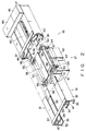
- Fig. 2 is a perspective view of a first track unit assembled in the transportation system shown in Fig. 1;
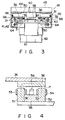
- Fig. 3 is a sectional view of the first track unit shown in Fig. 2;
- Fig. 4 is a sectional view of a magnetic unit for floating a carrier from a guide rail in a non-contact manner;
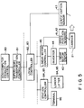
- Fig. 5 is a view showing an arrangement of a control apparatus of the transportation system shown in Fig. 1;
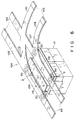
- Fig. 6 is a perspective view of a fifth track unit or curved branch unit assembled in the transportation system shown in Fig. 1;
- Fig. 7 is a plan view of a flat coupling rail provided to the fifth track unit or curved branch unit;
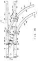
- Fig. 8 is a plan view of a coupling rail having a ridge, which is provided to the curved branch unit;
- Fig. 9 is a sectional view of the coupling rail and the magnetic unit;
- Fig. 10 is a view showing an arrangement of a control apparatus in the curved branch unit;
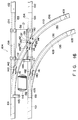
- Fig. 11 is a plan view of the curved branch unit;
- Figs. 12 and 13 are sectional views taken along a line XII - XII in Fig. 11, in which Fig. 12 shows a case wherein the carrier is transferred from a first rail to a second rail, and Fig. 13 shows a case wherein the carrier is transferred from the first rail to a third rail;
- Figs. 14 to 16 are plan views of the curved branch unit, in which Fig. 14 shows a case wherein the carrier enters the first coupling rail, Fig. 15 shows a case wherein the carrier is transferred onto a third coupling rail, and Fig. 16 shows a case wherein the carrier is transferred onto a second coupling rail;
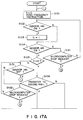
- Figs. 17A and 17B are flow charts of the control apparatus in the curved branch unit;
- Fig. 18 is a plan view of a curved branch unit according to a first modification;
- Fig. 19 is a plan view of a curved branch unit according to a second modification;
- Fig. 20 is a sectional view of the coupling rail and the magnetic unit according to a third modification; and
- Fig. 21 is a plan view of a curved branch unit according to a fourth modification.
- Fig. 1 shows
track assembly 10 of a transportation system of a floated-carrier type according to the present invention. In this transportation system,carrier 21 is suspended fromtrack assembly 10 in a non-contact manner, and is propelled along the track assembly. - As shown in Fig. 1,
track assembly 10 is constituted by annular main line 11, U-shapedbranch line 12 extending transversally from main line 11, andlinear branch line 13 extending transversally from main line 11. Main line 11 is connected tofirst station 91 for loading a cargo transported from a warehouse or the like or unloading the cargo fromcarrier 21 and transporting the cargo to the warehouse or the like. Main line 11 is also connected tosecond station 92 for maintaining and inspecting carrier 11.Third station 93 for unloading or loading a cargo from or ontocarrier 21 is provided besidebranch lines stations 91 to 93 comprisesloader 94 for loading a cargo ontocarrier 21 and lifter 95 for lifting the cargo betweenloader 94 and a predetermined position. (These stations are described in INTERNATIONAL CONFERENCE ON MAGLEV AND LINER DRIVES. May, 1987.) -
Track assembly 10 is constituted by selectively combining a plurality of track units. In this transportation system, five types of track units are combined.First track unit 16 is a straight track unit for propellingcarrier 21 along a straight track.Second track unit 17 is a curved track unit for propellingcarrier 21 along a curved track.Third track unit 18 is a rotary branch unit in which two tracks are perpendicularly branched, and which is used for rotatingcarrier 21 so as to guide it from one track to the other track.Fourth track unit 19 is an orthogonal branch unit in which two tracks are perpendicularly branched and which is used for guidingcarrier 21 from one track to the other track without rotatingcarrier 21.Fifth track unit 20 is a curved branch unit in which a curved track is branched from a straight track. - First track unit or
straight track unit 16 will be described with reference to Figs. 2 and 3. -
First track unit 16 comprises a pair ofsupport members 31 each of which is formed of a non-ferromagnetic material, extends longitudinally by a predetermined length, and has an E-shaped section. Eachsupport member 31 hasvertical base member 32.Upper flange 33,middle flange 34, andlower flange 35 extend from eachbase member 32. A pair ofguide rails 36 are mounted on lower surfaces ofmiddle flanges 34. Eachguide rail 36 is formed of a ferromagnetic material, and extends longitudinally by a predetermined length. The pair ofsupport members 31 are coupled by a plurality ofcoupling members 37. -
Stator 40 for a linear induction motor constituting propelling means is provided tofirst track unit 16.Stator 40 is supported on the lower surfaces of twocoupling members 37.Stator 40 is arranged to face reaction plate 58 (to be described later). - First or position sensor 41 for detecting if
carrier 21 passes a predetermined position, and second or speed sensor 42 for detecting a speed whencarrier 21 passes the predetermined position, are mounted on the side surface of onebase member 32. Third oridentification sensor 43 for identifying the type ofcarrier 21 is mounted on the side surface of theother base member 32.Inverter 44 andlinear motor controller 45 are mounted on the upper surface of oneend coupling member 37.Inverter 44 supplies three-phase AC power tostator 40.Linear motor controller 45 controls the three-phase AC power supplied frominverter 44 tostator 40 in accordance with detection signals from first and second sensors 41 and 42. Thus,carrier 21 is accelerated, decelerated, or stopped. - Furthermore, in
track unit 16,electrical wire 46 is mounted on the side surface of eachbase member 32.Electrical wire 46 includes a power wire, connected to, e.g.,inverter 44 andstator 40, for supplying power thereto, and a signal wire connected to first to third sensors 41 to 43,inverter 44, andlinear motor controller 45, for transmitting electrical signals. A pair ofconnectors 47 are provided to both ends ofelectrical wire 46. Thus, when a plurality of track units are assembled, a connector of one track unit and that of the other track unit are connected to each other to complete connection of electrical wires necessary for this system. For this reason, a mounting operation of electrical wires in the track can be omitted. Of course, upon connection of the connectors, eachelectrical wire 46 is connected to an electrical power source (not shown) orlocal controllers 82 and 83 and supervisory transportation controller 81 (to be described later). -
Carrier 21 will be described hereinafter. -
Carrier 21 comprises flat supportingplate 51 which is located belowguide rail 36. Fourmagnetic units 50 are arranged at four corners of supportingplate 51.Magnetic units 50cause carrier 21 to float fromguide rails 36 in a non-contact manner. As is shown in Fig. 4,magnetic units 50 are each provided withyokes guide rail 36. Conducting wires are wound around yokes 51 and 52, thus formingcoils rail 36.Permanent magnet 55 is used to coupleyokes magnet 55, yokes 51 and 52, gap P, andrail 36 constitute a magnetic circuit. Each magnetic unit is further provided withgap sensor 56 for detecting the clearance of gap P. -
Carrier 21 is suspended floating fromguide rails 36, in a non-contact manner, by means of a magnetic attractive force acting betweenmagnetic units 50 andguide rail 36. In this embodiment,units 50 are controlled by zero-power control device, so that the minimum necessary circuit current is supplied tocoils carrier 21 is made to float. In other words, fourpermanent magnets 55 always generate an attractive force equal to the total weight ofcarrier 21 itself and the load. At the same time, coils 53 and 54 are excited, so as to maintain the air gap clearance at which the attractive force betweenpermanent magnets 55 andrail 36 balances with the total weight of the carrier itself and the load.Coils cause carrier 21 to float. If the total weight ofcarrier 21 is changed by the load, the current fed to coils 53 and 54 is controlled so that gap P is adjusted to a distance such that the total attractive force betweenpermanent magnets 55 andguide rails 36 balances the total weight ofcarrier 21 and the load. In other words, by controlling the current fed to the coils, clearance of gap P is adjusted to a value such thatcarrier 21 is caused to float by means of the magnetic energy ofpermanent magnet 55 only, despite the existence of disturbances. (The zero-power control device is described in detail in EPC Appl. Ser. No. 85105028.6 filed previously by the applicant hereof,)
According to the zero-power control, power required for keeping the carrier in a floating state can be reduced. For this reason, a battery mounted on the carrier need not be frequently charged, and the carrier can be continuously propelled over a long period of time.Control box 57 storing the battery and the zero-power control device is mounted on the upper surface of supportingplate 51. -
Reaction plate 58 constituting a propelling means is mounted at the center of the upper surface of supportingplate 51.Reaction plate 58 facesstator 40. Ifstator 40 is supplied with current, a traveling magnetic field is generated instator 40, so that the current is induced toreaction plate 58. Through an interaction between the traveling field and the induced current,reaction plate 58 is subjected to thrust fromstator 40, and a propelling force along the guide rail is applied to the carrier. - As shown in Figs. 2 and 3,
hook 61 extends downward from the side edge of supportingplate 51.Carrier box 62 for storing a cargo is mounted on the distal end portion ofhook 61.Wheels 64 are provided to the side edges of supportingplate 51.Wheels 64 are in contact with upper surfaces of correspondinglower flanges 35 ofsupport members 31 whenmagnetic units 50 do not generate a magnetic attraction force.Wheels 66 are also provided abovewheels 64.Wheels 66 are in contact with the lower surfaces ofmiddle flanges 34 ofsupport members 31 whencarrier 21 is lifted to its uppermost position.Bar code 67 is provided to the side surface ofcarrier 21.Bar code 67 is located to face first to third sensors 41 to 43. First to third sensors 41 to 43read bar code 57, so as to detect if the carrier passes the predetermined position, a speed when the carrier passes the predetermined position, and the type of carrier. - Second track unit or
curved track unit 17 is substantially the same asfirst track unit 16 except that its track is curved. - Third track unit or
rotary branch unit 18 comprises a coupling section for coupling the guide rail of main line 11 and guide rails ofbranch lines branch line 12. Therefore, whencarrier 21 receives an instruction for transferring the carrier from the main line to the branch line, the carrier, having so far been running along the main line, is stopped at the coupling section, then rotated, then stopped from rotating when the carrier faces the branch line, and then transferred from the coupling section to the second rail section, all in a non-contact manner. (This third track unit is disclosed in detail in EPC Appl. Ser. No. 87302685,0 filed previously by the applicant hereof,)
Fourth track unit ororthogonal branch unit 19 comprises the coupling section and the transfer means as in the third track unit. For this reason, whencarrier 21 receives an instruction for transferring the carrier frombranch line 13 tobranch line 70, the carrier, having so far been running alongbranch line 13, is stopped at the coupling section, and is then transferred from the coupling section to thebranch line 70, all in a non-contact manner. Unlikethird track unit 18, infourth track unit 19, the carrier is not rotated when it is stopped at the coupling section. For this reason, onbranch line 70,carrier 21 travels in a transverse direction thereof.Third station 93 is connected tobranch line 70 extending fromfourth track unit 19. Whencarrier 21 is stopped onbranch line 70,third station 93 loads/unloads a cargo onto/fromcarrier 21. In this case, the subsequent carrier can pass by the stopping carrier. Thus, a travel time of the carrier can be shortened, and a transportation time of the cargo in this transportation system can be shortened. -
Fourth track unit 19 may be mounted on main line 11. In this case, the carrier temporarily stands by on the branch line extending fromfourth track unit 19. Thus, a large number of carriers on the main line can smoothly travel without causing traffic jam. (The fourth track unit is disclosed in detail in EPC Appl. Ser. No. 87302686,8 filed previously by the applicant hereof,)
Fifth track unit orcurved branch unit 20 will be described later in detail. - When these
track units 16 to 20 are appropriately combined, main line 11 andbranch line 12 are constituted. Each track unit comprises elements necessary for traveling the carrier. When a connector of one track unit is connected to a connector of the other track unit, connection of electrical wires necessary for this system can be completed. For this reason, a mounting operation of electrical wires in the track can be omitted, thus facilitating installation of the track. - Furthermore, when the travel path of the carrier is modified, a combination of track units are freely changed, so that various travel paths of the carrier can be realized. Thus, the travel path can be easily modified. Furthermore, when one track unit is malfunctioned, the track unit can be replaced with a new one. For this reason, maintenance and inspection of the system can be facilitated.
- A charging power source for charging the battery mounted on
carrier 21 is provided to this system.Carrier 21 comprises a first terminal connected to the battery. For example,branch line 70 is provided with a second terminal connected to the charging power source. When the carrier is stopped atbranch line 70, the first and second terminals are brought into contact with each other, and the charging power source supplies power to the battery via the first and second terminals. Since the battery is charged while the cargo is loaded/unloaded onto/from the carrier, the loading/unloading time can be effectively utilized. (The charging power source is disclosed in detail in EPC Appl. Ser. No. 87304289,9 filed previously by the applicant her of,)
In order to control travel of the carrier,supervisory transportation controller 81 and a plurality oflocal controllers 82 and 83 are provided to this transportation system, as shown in Fig. 5.Supervisory transportation controller 81 is connected to host computer forproduction control 80.Host computer 80 manages production control for the entire plant, and creates instruction regarding transportation jobs forsupervisory transportation controller 81.Supervisory transportation controller 81 manages and monitors the overall transportation system and distributescarriers 21 in an optimum timing and sequence to perform the transportation job instructed by a host computer. Local controller 82 performs traffic control of the carriers traveling along main line 11, and supplies an instruction for controllingfirst station 91 to station controller 84.Local controller 83 performs traffic control of the carriers traveling alongbranch lines third station 93 to station controller 85. Station controllers 84 and 85control loader 94 andlifter 95. Each station is provided withterminal 86. An operator can operate terminal 86 to create the transportation job. The speed and position of the carrier are detected by speed sensor 41 and position sensor 42, and the detection signals are supplied tolinear motor controller 45.Identification sensor 43 identifies the type of carrier, and the detection signal is supplied tolocal controller 83. When the electrical power source is malfunctioned, an auxiliary electrical power source is provided to the system so that power is kept supplied to the transportation system without cutting off power supply to the transportation system. - As described above, in the transportation system, the carrier travels while being suspended from the guide rails in a non-contact manner. For this reason, during traveling of the carrier, neither noise, vibration, nor dust are generated. The carrier and the guide rails are not in mechanical contact with each other. When the carrier begins to travel and is stopped, no impact force is applied to the carrier. Thus, the cargo receives no impact force. Furthermore, the carrier propelled by the linear motor while being suspended from the guide rails in a non-contact manner. For this reason, the carrier can be accelerated and decelerated immediately.
- Fifth track unit or
curved branch unit 20 will be described in detail. - The necessity of the branch unit will be explained first. In this transportation system, a large number of carriers must travel among various locations in a factory within a short period of time. For this purpose, a large number of carriers which travel along a track must be subjected to traffic control. In order to facilitate the traffic control, as shown in Fig. 1, the track preferably has a main line coupling principal points, and a large number of branch lines branching from the main line and coupled to subpoints. For this reason, a large number of branch units for transferring the carrier from the main line to the branch line and vice versa are necessary. That is, if a large number of branch units are not provided to the track, a large number of carriers cause traffic jam, and traffic control may become impossible. Prior art examples of the branch unit are disclosed in the following publications:
U.S. Pat. No. 4,109,508 describes a transportation system, which is provided with a rail-switching device at a diverging section, where branch lines diverge from main lines. When the switching device is operated mechanically, the main lines are disconnected from one another, and are connected to branch lines, so that a carrier can be transferred from the main lines to the branch lines. - In a system described in Japanese Patent Disclosure No. 50-150112, no rail switching device is provided, and main and branch lines are connected directly at a diverging section. A guide plate is provided at the diverging section, whereby the rollers of a carrier are guided from the diverging section to the branch lines. As the rollers slide along the guide plate, the carrier is transferred from the main lines to the branch lines.
- As has been described above, however, the branch unit for transferring the carrier, from the main lines to the branch lines, requires a mechanical switching device. Therefore, the branch unit is increased in size, thereby reducing the available space in the factory. Moreover, the switching device is operated mechanically, and especially in the system stated in Japanese Patent Disclosure No. 50-150112, the rollers of the carrier are in contact with the guide plate while the carrier is being transferred. As a result, noise is produced by the transfer apparatus.
- Thus, such a transfer apparatus is liable to spoil the environment of the factory, in which case the main lines should not be provided with a large number of branch units. In this case, therefore, the carrier cannot run smoothly along the guide rail, and can reach its destination only after a long period of time.
- The present inventors thus proposed third track unit or
rotary branch unit 18 and fourth track unit ororthogonal branch unit 19 described above. In these branch units, a carrier is not in contact with the guide rails, and is transferred from one line to another line without producing noise. In addition, the size of the branch unit can be reduced. However, in these branch units, a carrier is temporarily stopped at the branch unit, and thereafter, is transferred from one line to another line. For this reason, a relatively long period of time is required in order to transfer the carrier from one line to another line. Thus, the carrier can reach its destination only after a long period of time. - The present inventors proposed fifth track unit or
curved branch unit 20 in which a carrier is transferred from one line to another line without being stopped at the branch unit. - The arrangement of fifth track unit or
curved branch unit 20 will be described. - As shown in Fig. 6, guide rails of track units adjacent to branch
unit 20 are defined asfirst rails 101,second rails 102, andthird rails 103. First andsecond rails third rails 103 intersect first andsecond rails coupling section 104 for coupling first tothird rails 101 to 103.Coupling section 104 comprises first coupling rails 105 and 106, second coupling rails 107 and 108, and third coupling rails 109 and 110. One end of each of first to third coupling rails 105 to 110 is connected to corresponding one of first tothird rails 101 to 103. The other end of each of first coupling rails 105 and 106 is coupled to the other end of corresponding one of second and third coupling rails 107 to 110. As a result, forkedrail joining sections third rails 101 to 103, and is also the same as that between a pair ofmagnetic units 50. - As shown in Fig. 6,
stator 116 of the linear induction motor is mounted on support members (not shown).Stator 116 is located to facereaction plate 58 of the carrier.Stator 116 andreaction plate 58 constitute a means for transferring the carrier from one rail pair to another rail pair. - The carrier is suspended from the coupling rails in a non-contact manner by an electromagnetic attractive force between
magnetic unit 50 and each coupling rail. In this case,magnetic unit 50 may be subjected to zero-power control described above. - The carrier is transferred from the first rails to second or third rails (former case), and is transferred from the second or third rails to the first rails (latter case). In the former case, the carrier coasting by receiving a predetermined propelling force from
stator 40, enters fromfirst rails 101 to first coupling rails 105 and 106. The carrier travels along the first coupling rails by the predetermined propelling force without being interfered. During travel of the carrier, when stator 116biases reaction plate 58 in a direction indicated by arrow D, the carrier is guided from first coupling rails 105 and 106 to second coupling rails 107 and 108. Thereafter, the carrier keeps traveling by the predetermined propelling force and is guided tosecond rails 102. During travel of the carrier on the first coupling rails, when stator 116biases reaction plate 58 in a direction indicated by arrow E, the carrier is guided from the first coupling rails 105 and 106 to third coupling rails 109 and 110. Thereafter, the carrier keeps traveling by the predetermined propelling force and is guided tothird rails 103. Therefore, the carrier is transferred to predetermined rails while being suspended from the coupling rails in a non-contact manner without being stopped at the coupling rails. - First coupling rails 105 and 106 are arranged along the same lines as second coupling rails 107 and 108, and obliquely intersect third coupling rails 109 and 110. In the latter case, the carrier need not receive a transfer force in the direction indicated by arrow D or E, and is automatically guided from the second or third coupling rails to the first coupling rails.
- However, when first to third coupling rails are formed to have a planar shape, the carrier may often fail to reliably transfer from
first rails 101 tothird rails 103. The reason will be explained below. - In Fig. 6, when the carrier which travels on
first rails 101 reaches predetermined positions of first coupling rails 105 and 106, it receives a transfer force in a direction of third coupling rails 109 and 110. In this case, ifyokes magnetic units 50 do not constitute magnetic circuits together with the corresponding coupling rails, no electromagnetic attractive force is generated therebetween. For this reason, yokes 51 and 52 must be moved alongfirst coupling rail 105,rail joining section 111, andthird coupling rail 109, as indicated by arrow F in Fig. 7. However, yokes 51 and 52 generate magnetic flux leakage, and magnetic resistance formagnetic unit 50 in region B1 is smallest inrail joining section 111. For this reason, when yokes 51 and 52 reach point A1 in Fig. 7, magnetic flux leakage is biased in region B1. As a result, a guide force for attractingyokes yokes third coupling rail 109 competes with this guide force. As a result, yokes 51 and 52 are reciprocated along the transverse direction of the rail. When the guide force overcomes the transfer force, oneyoke 51 is moved tosecond coupling rail 107 and anotheryoke 52 is moved tothird coupling rail 109 at forkedrail joining section 111. As a result, ifcarrier 21 keeps traveling, the magnetic circuits formed bymagnetic units 50 and coupling rails are disabled. For this reason, the magnetic units may be separated from the coupling rails, and the carrier may be dropped. - In order to suppress reciprocal motion of
yokes yokes - According to the present invention, however, as shown in Figs. 8, 9, and 11, pairs of first and
second ridges 131 to 136 are formed at two sides of each coupling rail. First andsecond ridges yokes magnetic units 50. More specifically, the width of each of first andsecond ridges 131 to 136 is substantially the same as that of each ofyokes - In Fig. 8, when the carrier enters
first coupling rail 105, magnetic flux leakage fromyokes only ridges yokes yokes yokes ridges magnetic units 50 and the coupling rails are not disabled at forkedrail joining section 111. The carrier can be reliably transferred fromfirst rails 101 tosecond rails 103. - When the relatively large transfer force is applied to the carrier, since a force for preventing
yokes magnetic units 50 and the coupling rail cannot be disturbed and hence, the carrier cannot be dropped. - Therefore, the carrier can be transferred from one line to another line without being stopped at the branch unit. For this reason, fifth track unit or
curved branch unit 20 has a shorter transfer time than third track unit orrotary branch unit 18, and the like. A time required until the carrier reaches the destination can be shortened. - The carrier is transferred in a non-contact manner from the coupling rail. Therefore, no noise is generated. Furthermore, since the transfer means comprises the linear induction motor, the branch unit can be rendered compact. Therefore, a large number of branch units can be provided in a small space in a factory. Traffic control of a large number of carriers can be allowed, and a travel time of each carrier can be shortened.
- As shown in Fig. 11,
ridge intersection 140 at whichfirst ridge 133 of the first coupling rail andsecond ridge 136 of the third coupling rail intersect each other is formed at each ofrail joining sections ridge intersection 140. Fig. 12 shows a case whereinmagnetic unit 50 is moved toward second coupling rails 107 and 108. Fig. 13 shows a case whereinmagnetic unit 50 is moved toward third coupling rails 109 and 110. Atridge intersection 140, tworidges ridge intersection 140 is larger than that ofyokes ridge intersection 140 has region C1 which does not faceyoke 52. Since the magnetic resistance of region C1 is smaller than the opposite side ofridge intersection 140 region C1, magnetic flux leakage fromyoke 52 is flowed in region C1. For this reason, a force for attractingyoke 52 toward region C1 is applied toyoke 52. As a result,yoke 52 is swung. - According to the present invention,
ferromagnetic projection 141 is provided to the side surface of eachridge intersection 140. Thus,yoke 52 receives attractive forces from both region C1 andprojection 141. Since the two attractive forces are balanced,yoke 52 can be prevented from being attracted toward only region C1. As a result, swinging motion ofyoke 52 can be prevented. - As shown in Fig. 13, when
magnetic unit 50 is moved toward third coupling rails 109 and 110,ridge intersection 140 has region C2 which does not faceyoke 51.Ferromagnetic projection 142 is provided to the side surface ofridge intersection 140. Thus,yoke 51 can be prevented from being attracted toward region C2, and can also be prevented from being swung.Projection - As shown in Fig. 11,
coupling section 104 hasrail intersection 137 at which onesecond coupling rail 107 and onethird coupling rail 110 intersect each other.Rail intersection 137 has a plurality ofridge intersections 139 at which first andsecond ridges second coupling rail 107 and first andsecond ridges third coupling rail 110 intersect each other.Projections ridge intersection 139. Thus, yokes 51 and 52 can be prevented from being attracted toward region C1 and C2, and can also be prevented from being swung. - A control apparatus of
branch unit 20 will be described hereinafter. - As shown in Fig. 11,
photo sensor 145 is provided at an end portion offirst coupling rail 106 nearfirst rail 101.Photo sensor 146 is provided to an end portion ofsecond coupling rail 107 nearrail joining section 111. Thesephotosensors reaction plate 58 of the carrier, and detect light reflected byplate 58.Sensor 145 detects whether or not the carrier enters first coupling rails 105 and 106, and generates a detection signal. More specifically,sensor 145 detects a timing when transfer of the carrier fromfirst rails 101 to second orthird rails Sensor 146 detects whether nor not the carrier enters second and third coupling rails 107 to 109, and generates a detection signal. More specifically,sensor 146 detects a timing when transfer of the carrier fromfirst rails 101 to second orthird rails - As shown in Fig. 10, three-phase
AC power source 148 is connected tostator 116 throughinverter 149. The detection signals fromsensors microcomputer 147.Microcomputer 147 also receives an instruction, supplied from an external apparatus e.g.,linear motor controller 45, for transferring the carrier to a predetermined rail, and an instruction for stoppingmicrocomputer 147.Microcomputer 147 determines the output frequency ofinverter 149 and a propagating direction of a moving magnetic field generated instator 116 based on these signals and instructions. - Note that as shown in Fig. 9,
magnetic unit 50 comprisesgap sensor 56 for detecting gap P betweenyokes grooves 151 are formed incoupling rails 105 to 110 between pairs ofridges 131 to 136. For this reason,gap sensor 56 cannot accurately detect the gap betweenridges 131 to 136 andyokes non-magnetic member 152 is stored in eachgroove 151. The top face ofnon-magnetic member 152 is located on the identical plane to the top face of the ridge. Therefore,gap sensor 56 emits light toward the top face ofnon-magnetic member 152, and detects light reflected by the top face. - The operation of the branch unit will be described below with reference to Figs. 14 to 17B.
- In the flow charts of Figs. 17A and 17B, in an initial state in
step 101, counter h = 0. In this case, the carrier is transferred fromfirst rails 101 to second orthird rails third rails first rails 101. Furthermore, in the initial state instep 101, sinceinverter 149 receives a zero-frequency instruction,stator 116 is not energized. - In
steps 102 to 104,sensors coupling section 104, the flow is looped insteps - A case will be described wherein the carrier is transferred from
first rails 101 to second orthird rails 102 or 103 (i.e., h = 0). - In Fig. 14, if the carrier traveles along
first rails 101 and receives a predetermined propelling force, the carrier keeps traveling without being stopped atcoupling rails 105 to 110. Whencarrier 21 reaches first coupling rails 105 and 106,sensor 145 is turned on (step 104). Instep 105, h = 0. It is checked instep 106 whether the carrier is transferred to second orthird rails third rails 103,inverter 149 receives an instruction of a moving magnetic field in a direction indicated by arrow E and a predetermined frequency instruction instep 108. Then, the carrier traveling along the first coupling rails receives a transfer force toward the third coupling rails, and transfer of the carrier is started. When the carrier is transferred by a predetermined distance,sensor 145 is turned off instep 109. If the carrier is further transferred by the predetermined distance,sensor 146 is turned on instep 110. Thereafter, when the carrier has reached a position shown in Fig. 15,sensor 146 is turned off instep 111. Thus, transfer of the carrier fromfirst rails 101 tothird rails 103 is ended. Flow returns to step 101, so thatinverter 149 receives a zero-frequency instruction and the energization ofstator 116 is stopped. The carrier keeps traveling alongthird rails 103. Until subsequent carrier reaches first coupling rails 105 to 110, the flow is looped insteps - If the carrier is transferred to
second rails 102,inverter 149 receives an instruction of a moving magnetic field in a direction indicated by arrow D and a predetermined frequency instruction instep 107. Other operations are the same as those when the carrier is transferred tothird rails 103. When the carrier has reached a position shown in Fig. 16, energization ofstator 116 is stopped. - A case will be described wherein the carrier is transferred from second or
third rails first rails 101. In this case, the carrier need not receive the transfer force fromstator 116. - When the carrier enters
coupling section 104 from second orthird rails sensor 146 is turned on instep 102. Instep 103, counter h = 1. The carrier travels along second or third coupling rails 107 and 108 or 109 and 110. When the carrier travels along first coupling rails 105 and 106 by a predetermined distance,sensor 145 is turned on instep 104. Thereafter, when the carrier travels alongfirst rails 101,sensor 145 is turned off instep 131. Then, the flow returns to step 101. The carrier keeps traveling alongfirst rails 101. - If a first microcomputer stop request, which is supplied to prevent
stator 116 from being energized at, for instance, trial traveling, is detected insteps 121 and 132, the flow jumps to an end. If a second microcomputer stop request, which is supplied to immediately stop the energization ofstator 116 in emergency, is detected insteps inverter 149, and the energization ofstator 116 is stopped. - As described above, a pair of ridges facing a pair of yokes are formed on each coupling rail. For this reason, magnetic flux leakage of each yoke is concentrated on only the ridge, and is not biased to other portions. Thus, a force for preventing the yoke from being shifted toward the transverse direction of the rail can be generated. The yoke is moved along the ridge, and swinging motion of the yoke can be prevented. Therefore, the magnetic circuit between the magnetic unit and the coupling rail cannot be disabled. The carrier can be reliably transferred from one line to another line, and cannot be dropped.
- Therefore, the carrier can be transferred from one line to another line without being stopped at the branch unit. For this reason, fifth track unit or
curved branch unit 20 has a shorter transfer time than third track unit orrotary branch unit 18. Therefore, a time required until the carrier reaches the destination can be shortened. - Moreover, the carrier is transferred in a non-contact manner, and hence, no noise is generated. Since the transfer means comprises the linear induction motor, the branch unit can be rendered compact. A large number of branch units can be provided to the track even in a small space in a factory. A large number of carriers can thus be subjected to traffic control, and a travel time of each carrier can be shortened.
- In the above embodiment, each
second coupling rail 102 is linearly formed. However, as shown in Fig. 18,second coupling rail 102 may be formed to have a curved shape. - As shown in Fig. 19,
coupling section 104 may be coupled to four track units. In this case, the carrier can be transferred fromfirst rails 101 to fourth coupling rails 161 and then fourth rails 162 by the same transfer means of above embodiment. - Fig. 20 shows a modification of the coupling rail. Two
grooves coupling rail 105 to 110, thus defining threeridges 131 to 136, and 173.Ridges 131 to 136, together withyoke Gap sensor 56 emits light toward the top face ofridge 173, so that the gap clearance betweenridges 131 to 136 andyokes non-magnetic member 152 may be omitted. - The branch unit may alternatively be designed so as to transfer
carrier 21 by utilizing air pressure. As is shown in Fig. 21, for example,air nozzles 163 may be arranged so that they can blow air againstcarrier 21, thereby transferring the carrier from first coupling rail to second or third coupling rail. - Furthermore, the number of yokes is not limited to two but may be three or more. If three or more yokes are arranged, each coupling rail need only have ridges corresponding in number to the yokes.
- According to the aforementioned embodiment, moreover, the guide rail includes a pair of guide rails. Alternatively, however, the guide rail used may be one, or three, or more, in number. Also, the magnetic unit may be constructed so that the carrier is caused to float by means of the magnetic force of the coils only, without using the permanent magnet.
Claims (14)
- A transportation system of a floated-carrier type for transporting a cargo between predetermined positions, characterized by comprising:
a guide rail means formed of a ferromagnetic material and including first rail (101), second rail (102), and third rail (103) intersecting the first rail (101), each rail extending longitudinally;
a carrier (21) for carrying the cargo;
magnetic unit (50) provided on the carrier (21), said magnetic unit (50) having at least a pair of yokes (51, 52) which have an air gap P, with respect to said guide rail means, and magnetic coils (53, 54) provided to said yokes (51, 52), said yokes (51, 52), said air gap P, and said guide rail means constituting a magnetic circuit, and said carrier (21) being adapted to be suspended from said guide rail means in a non-contact manner, by means of magnetic attractive force acting between said magnetic unit and said guide rail means, so that the air gap of a predetermined size is maintained between the yokes and said guide rail means;
a coupling section (104) for connecting the first to third rails (101 to 103) one another, said coupling section (104) including a coupling rail (105 to 110) formed of a ferromagnetic material and connecting the first to third rails (101 to 103) one another, said coupling rail (105 to 110) formed of a ferromagnetic material and having a pair of first and second ridges (131 to 136) respectively facing said yokes (51, 52), and each of said ridges (131 to 136) having a width substantially the same as that of each of said yokes (51, 52) in a transverse direction of the rail;
propelling means for providing a propelling force to said carrier (21) so as to cause said carrier (21) to travel along said guide rail means; and
transfer means (58, 116) provided at the coupling section (104), and adapted so that, at the coupling section, said carrier (21), having so far been running along the first rail (101), is transferred from the first rail (101) to the coupling rail (105 to 110), and is then transferred to the second or third rail (102 or 103) therefrom, all in a non-contact manner,
whereby when said carrier (21) enters the coupling rail (105 to 110), magnetic flux leakage from said yokes (51, 52) is concentrated on only said ridges without being biased to other portions, so that a force for preventing said magnetic unit (50) from being shifted in a transverse direction of the rail with respect to said ridges (131 to 136) is generated, and said carrier (21) is reliably transferred from the first rail (101) to either second or third rail (102 or 103). - A transportation system according to claim 1, characterized in that the coupling rail consists of a first coupling rail (105, 106), a second coupling rail (107, 108), and a third coupling rail (109, 110), one end of each of the first to third coupling rails (105 to 110) is connected to corresponding one of the first to third rails (101 to 103), the other end of the first coupling rail (105, 106) is connected to the other end of each of the second and third coupling rails (107 to 110), and each of said first to third coupling rails (105 to 110) has the first and second ridges (131 to 136).
- A transportation system according to claim 2, characterized in that said third coupling rail (109, 110) is formed into a curved shape having a predetermined radius of curvature, and intersects the first coupling rail (105, 106) at an obtuse angle.
- A transportation system according to claim 2, characterized in that said guide rail means has pairs of first to third rails (101 to 103), respectively, and said coupling section (104) has pairs of first to third coupling rails, respectively (105 to 110).
- A transportation system according to claim 1, characterized in that said magnetic unit (50) includes a permanent magnet (55) providing magnetic energy, with which the carrier (21) can be kept suspending against the weight thereof and the load thereon, and, the coils (53, 54) are adapted to be excited so as to maintain the gap clearance, at which the magnetic attractive force acting between the permanent magnet (55) and the guide rail balances with the total weight of the carrier (21) itself and the load, regardless of weight of the load.
- A transportation system according to claim 1, characterized in that said transfer means includes a stator (116) for a linear induction motor, which is arranged on said coupling section (104), and a reaction plate (58) for the linear induction motor, which is provided to said carrier (21) and is energized by said stator (116) in a transfer direction of said carrier (21).
- A transportation system according to claim 1, characterized in that said transfer means includes:
detection means for detecting whether or not said carrier (21) passes a position at which a stator (116) starts energization of a reaction plate (58) of said carrier (21), and detecting whether or not said carrier (21) passes a position at which the stator (116) stops energization of the reaction plate (58) of said carrier (21). - A transportation system according to claim 7, characterized in that said detection means includes a reflection type photo sensor (145, 146).
- A transportation system according to claim 2, characterized in that said coupling section (104) has a rail joining section (111, 112) at which the first to third coupling rails (105 to 110) are joined,
said rail joining section (111, 112) has a ridge intersection (140) at which the first ridge (133) of the second coupling rail (107, 108) intersects the second ridge (136) of the third coupling rail (109, 110), and
the ridge intersection (140) has, on a side surface thereof, a projection (141, 142) formed of a ferromagnetic material,
whereby magnetic flux leakage from the yoke (51, 52) is flowed to both the ridge intersection (140) and the projection (141, 142), the yoke (51, 52) can be prevented from being attracted toward the ridge intersection (140), and swinging motion of said carrier (21) can be prevented. - A transportation system according to claim 2, characterized in that the first to third coupling rails (105 to 110), the ridges (131 to 136) of the coupling rail (105 to 110), and the projection (141, 142) are integrally formed at the rail joining section (111, 112).
- A transportation system according to claim 4, characterized in that said coupling section has rail intersection (137) at which one second coupling rail (107) and one third coupling rail (110) intersect each other,
said rail intersection (137) has a plurality of ridge intersections (140) at which the first and second ridges (133, 134) of the second coupling rail (107) intersect the first and second ridges (135, 136) of the third coupling rail (110), respectively, and
each ridge intersection (140) has, on a side surface thereof, a projection (141, 142) formed of a ferromagnetic material,
whereby magnetic flux leakage from the yoke (51, 52) is flowed to both each ridge intersection (140) and each projection (141, 142), the yoke (51, 52) can be prevented from being attracted toward the ridge intersections (140), and swinging motion of the carrier (21) can be prevented. - A transportation system according to claim 11, characterized in that the second and third coupling rails (105 to 110), the ridges (131 to 136) of the coupling rail (105 to 110), and the projection (141, 142) are integrally formed at each rail intersection (137).
- A transportation system according to claim 1, characterized in that a groove (151) is defined between the ridges (131 to 136), and a non-magnetic member (152) is provided in the groove (151), so that a top face of the non-magnetic material (152) is located on an identical plane to a top face of the ridge (131 to 136).
- A transportation system according to claim 1, characterized in that each coupling rail (105 to 110) has two grooves (70, 71) which define the first and second ridges (131 to 136).
Applications Claiming Priority (3)
| Application Number | Priority Date | Filing Date | Title |
|---|---|---|---|
| JP303442/86 | 1986-12-19 | ||
| JP61303442A JP2501808B2 (en) | 1986-12-19 | 1986-12-19 | Magnetic levitation transfer system |
| EP87311213A EP0272897B1 (en) | 1986-12-19 | 1987-12-18 | Transportation system of a floated-carrier type |
Related Parent Applications (1)
| Application Number | Title | Priority Date | Filing Date |
|---|---|---|---|
| EP87311213.0 Division | 1987-12-18 |
Publications (3)
| Publication Number | Publication Date |
|---|---|
| EP0474321A2 true EP0474321A2 (en) | 1992-03-11 |
| EP0474321A3 EP0474321A3 (en) | 1992-04-15 |
| EP0474321B1 EP0474321B1 (en) | 1995-03-29 |
Family
ID=17921046
Family Applications (2)
| Application Number | Title | Priority Date | Filing Date |
|---|---|---|---|
| EP91202887A Expired - Lifetime EP0474321B1 (en) | 1986-12-19 | 1987-12-18 | Transportation system of a floated-carrier type |
| EP87311213A Expired - Lifetime EP0272897B1 (en) | 1986-12-19 | 1987-12-18 | Transportation system of a floated-carrier type |
Family Applications After (1)
| Application Number | Title | Priority Date | Filing Date |
|---|---|---|---|
| EP87311213A Expired - Lifetime EP0272897B1 (en) | 1986-12-19 | 1987-12-18 | Transportation system of a floated-carrier type |
Country Status (5)
| Country | Link |
|---|---|
| US (2) | US4882999A (en) |
| EP (2) | EP0474321B1 (en) |
| JP (1) | JP2501808B2 (en) |
| KR (1) | KR910002780B1 (en) |
| DE (2) | DE3788115T2 (en) |
Cited By (1)
| Publication number | Priority date | Publication date | Assignee | Title |
|---|---|---|---|---|
| FR2680483A1 (en) * | 1991-08-22 | 1993-02-26 | Mtu Muenchen Gmbh | REGULATION DEVICE WITH FREQUENCY FILTERS FOR ADJUSTING THE GAP OF ELECTROMAGNETIC LIFT SYSTEMS. |
Families Citing this family (33)
| Publication number | Priority date | Publication date | Assignee | Title |
|---|---|---|---|---|
| JPS6416101U (en) * | 1987-07-17 | 1989-01-26 | ||
| US5170714A (en) * | 1988-06-13 | 1992-12-15 | Asahi Glass Company, Ltd. | Vacuum processing apparatus and transportation system thereof |
| DE3900511A1 (en) * | 1989-01-10 | 1990-07-12 | Magnet Motor Gmbh | AUTOMATIC GOODS TRANSPORT DEVICE WITH LINEAR MOTOR DRIVE TRANSPORT ELEMENTS |
| US5049218A (en) * | 1989-12-04 | 1991-09-17 | Geoffrey Martin | Magnetic support & transport system |
| US5228820A (en) * | 1990-09-21 | 1993-07-20 | Advanced Technology And Research Corporation | Article handling system with distributed storage |
| US5281558A (en) * | 1992-11-02 | 1994-01-25 | Cadence Design Systems, Inc. | Cloning method and system for hierarchical compaction |
| DE4413899A1 (en) * | 1994-04-21 | 1995-10-26 | Magnetbahn Gmbh | Linear motor vehicle with permanent electromagnetic control |
| FR2738005B1 (en) * | 1995-08-22 | 1997-11-14 | Flix Jean Marie | DEVICE FOR SPACING PRODUCTS OR BATCHES OF PRODUCTS |
| US6450103B2 (en) | 1996-05-07 | 2002-09-17 | Einar Svensson | Monorail system |
| US5845581A (en) * | 1996-05-07 | 1998-12-08 | Svensson; Einar | Monorail system |
| US6182576B1 (en) | 1996-05-07 | 2001-02-06 | Einar Svensson | Monorail system |
| DE19725644A1 (en) * | 1997-06-18 | 1998-12-24 | Alsthom Cge Alcatel | Track for rail tracks branched by means of switches |
| DE10158763A1 (en) * | 2001-11-29 | 2003-07-10 | Abb Patent Gmbh | Luggage transport system over long distances |
| TWI290272B (en) * | 2004-03-12 | 2007-11-21 | Murata Machinery Ltd | Moving body system |
| US7448012B1 (en) | 2004-04-21 | 2008-11-04 | Qi-De Qian | Methods and system for improving integrated circuit layout |
| JP4148194B2 (en) * | 2004-07-22 | 2008-09-10 | 村田機械株式会社 | Conveyor cart system |
| CN101048861B (en) * | 2004-08-23 | 2010-05-26 | 布鲁克斯自动化公司 | Elevator-based tool loading and buffering system |
| US7677180B2 (en) * | 2005-06-09 | 2010-03-16 | International Business Machines Corporation | Apparatus and method for steering transport vehicles in semiconductor processing |
| KR100675314B1 (en) * | 2005-12-30 | 2007-01-29 | 한국기계연구원 | Moving apparatus of switch and crossing for magnetically levitated vehicle |
| US7757609B2 (en) * | 2006-10-10 | 2010-07-20 | Launchpoint Technologies, Inc. | Track switching for a magnetically levitated transportation system and method |
| KR100913795B1 (en) * | 2007-11-30 | 2009-08-31 | 성삼경 | Maglev train |
| JP5217623B2 (en) * | 2008-05-19 | 2013-06-19 | 株式会社安川電機 | Magnetic levitation controller |
| KR101974185B1 (en) * | 2012-06-25 | 2019-04-30 | 세메스 주식회사 | Magnetic levitation transfer apparatus and method |
| US9228298B2 (en) * | 2013-03-14 | 2016-01-05 | Daryl Oster | Evacuated tube transport system with interchange capability |
| EP3176111B1 (en) * | 2015-12-04 | 2020-02-12 | BEUMER Group GmbH & Co. KG | Item sorting device and method |
| CN106087622B (en) * | 2016-07-22 | 2018-01-09 | 株洲时代电子技术有限公司 | The index point device fixed based on magnetic force |
| DE102016224951A1 (en) * | 2016-12-14 | 2018-06-14 | Robert Bosch Gmbh | Conveying device with a stator for the controlled transport of a transport body relative to the stator |
| CN108638914B (en) * | 2018-07-04 | 2021-08-17 | 中车株洲电力机车有限公司 | Suspension type maglev transportation system and maglev train suspension frame thereof |
| CN109081059B (en) * | 2018-09-28 | 2023-12-01 | 德瑞精工(深圳)有限公司 | Conveying device and workpiece rail transferring method |
| CN109399218A (en) * | 2018-11-21 | 2019-03-01 | 中铁第四勘察设计院集团有限公司 | A kind of circulating continuous receive-transmit system of Cold Chain Logistics pipe-line system and method |
| JP7300281B2 (en) * | 2019-03-08 | 2023-06-29 | 株式会社日立ハイテク | Transporting device, sample analysis system provided with same, sample pretreatment device, and transporting method for transported object |
| JP7410615B2 (en) | 2019-09-03 | 2024-01-10 | キヤノン株式会社 | Processing system and article manufacturing method |
| CN113944691B (en) * | 2021-09-22 | 2022-04-29 | 哈尔滨工业大学 | Movable air-float guide mechanism |
Citations (3)
| Publication number | Priority date | Publication date | Assignee | Title |
|---|---|---|---|---|
| US3736880A (en) * | 1971-04-19 | 1973-06-05 | Rohr Industries Inc | Feedback control circuit for magnetic suspension and propulsion system |
| US4109584A (en) * | 1976-12-22 | 1978-08-29 | Japan Airlines Co., Limited | Track switching device for two-rail type tracks |
| EP0179188A2 (en) * | 1984-10-23 | 1986-04-30 | Kabushiki Kaisha Toshiba | Transporting system of floated carrier type |
Family Cites Families (14)
| Publication number | Priority date | Publication date | Assignee | Title |
|---|---|---|---|---|
| DE1194745B (en) * | 1959-01-17 | 1965-06-10 | Adolf Opfermann Dipl Chem | Track for toy and model railways with additional electrical conductors |
| BE741218A (en) * | 1968-11-15 | 1970-04-16 | ||
| US3570177A (en) * | 1970-01-29 | 1971-03-16 | Remco Ind Inc | Toy monorail train system |
| US3937148A (en) * | 1973-01-02 | 1976-02-10 | Cambridge Thermionic Corporation | Virtually zero power linear magnetic bearing |
| CA1044774A (en) * | 1974-07-26 | 1978-12-19 | Gotz Heidelberg | Magnetic system for supporting and propelling a vehicle along a roadway |
| DE2939540A1 (en) * | 1979-09-28 | 1981-04-02 | Siemens AG, 1000 Berlin und 8000 München | Set of points for linear motor vehicle rails - has excitation coils attached to rails before and after interruption zone |
| JPS619104A (en) * | 1984-06-20 | 1986-01-16 | Fuji Electric Co Ltd | Magnetic levitating conveyor |
| JPH06101884B2 (en) * | 1985-03-29 | 1994-12-12 | 株式会社東芝 | Floating carrier |
| JP2680296B2 (en) * | 1985-03-29 | 1997-11-19 | 株式会社東芝 | Floating transfer device |
| JPH0687603B2 (en) * | 1986-03-27 | 1994-11-02 | 株式会社東芝 | Floating carrier |
| JP2609588B2 (en) * | 1986-05-14 | 1997-05-14 | 株式会社東芝 | Floating transfer device |
| JP2732562B2 (en) * | 1986-05-14 | 1998-03-30 | 株式会社東芝 | Floating transfer device |
| US4678981A (en) * | 1986-08-01 | 1987-07-07 | Spacesaver Corporation | Portable power source for mobile storage carriage |
| US4718621A (en) * | 1986-10-24 | 1988-01-12 | Shinko Electric Co., Ltd. | Automatic transportation system |
-
1986
- 1986-12-19 JP JP61303442A patent/JP2501808B2/en not_active Expired - Lifetime
-
1987
- 1987-12-05 KR KR1019870014416A patent/KR910002780B1/en not_active IP Right Cessation
- 1987-12-18 DE DE87311213T patent/DE3788115T2/en not_active Expired - Fee Related
- 1987-12-18 EP EP91202887A patent/EP0474321B1/en not_active Expired - Lifetime
- 1987-12-18 DE DE3751208T patent/DE3751208T2/en not_active Expired - Fee Related
- 1987-12-18 US US07/135,084 patent/US4882999A/en not_active Expired - Lifetime
- 1987-12-18 EP EP87311213A patent/EP0272897B1/en not_active Expired - Lifetime
-
1989
- 1989-02-02 US US07/305,191 patent/US4934279A/en not_active Expired - Fee Related
Patent Citations (3)
| Publication number | Priority date | Publication date | Assignee | Title |
|---|---|---|---|---|
| US3736880A (en) * | 1971-04-19 | 1973-06-05 | Rohr Industries Inc | Feedback control circuit for magnetic suspension and propulsion system |
| US4109584A (en) * | 1976-12-22 | 1978-08-29 | Japan Airlines Co., Limited | Track switching device for two-rail type tracks |
| EP0179188A2 (en) * | 1984-10-23 | 1986-04-30 | Kabushiki Kaisha Toshiba | Transporting system of floated carrier type |
Non-Patent Citations (1)
| Title |
|---|
| IEEE INT. CONF. ON MAGLEV AND LINEAR DRIVES May 1986, VANCOUVER,CA pages 199 - 210; MORISHITA: 'A New Maglev System for Magnetically Levitated Carrier System.' * |
Cited By (1)
| Publication number | Priority date | Publication date | Assignee | Title |
|---|---|---|---|---|
| FR2680483A1 (en) * | 1991-08-22 | 1993-02-26 | Mtu Muenchen Gmbh | REGULATION DEVICE WITH FREQUENCY FILTERS FOR ADJUSTING THE GAP OF ELECTROMAGNETIC LIFT SYSTEMS. |
Also Published As
| Publication number | Publication date |
|---|---|
| EP0272897A2 (en) | 1988-06-29 |
| EP0474321A3 (en) | 1992-04-15 |
| US4934279A (en) | 1990-06-19 |
| DE3751208T2 (en) | 1995-08-24 |
| DE3788115D1 (en) | 1993-12-16 |
| DE3788115T2 (en) | 1994-05-05 |
| JPS63157602A (en) | 1988-06-30 |
| EP0272897B1 (en) | 1993-11-10 |
| KR880007292A (en) | 1988-08-26 |
| JP2501808B2 (en) | 1996-05-29 |
| US4882999A (en) | 1989-11-28 |
| EP0272897A3 (en) | 1989-05-24 |
| KR910002780B1 (en) | 1991-05-04 |
| EP0474321B1 (en) | 1995-03-29 |
| DE3751208D1 (en) | 1995-05-04 |
Similar Documents
| Publication | Publication Date | Title |
|---|---|---|
| US4882999A (en) | Transportation system of a floated-carrier type | |
| US5156093A (en) | Transportation system of floated-carrier type | |
| EP0246096B1 (en) | Transportation system of a floated-carrier type | |
| EP0288615B1 (en) | Transportation system of a floated-carrier type | |
| JP3327367B2 (en) | Transfer equipment | |
| KR900006247B1 (en) | Transportation system of a floated-carrier type | |
| JP3109737B2 (en) | Floating transfer device | |
| JPS627305A (en) | Levitating conveying apparatus | |
| JPH04117111A (en) | Magnetic levitation conveyor | |
| JP2634044B2 (en) | Magnetic levitation transfer device | |
| JPS61132005A (en) | Levitating conveyor | |
| JPS61224807A (en) | Levitating conveyor | |
| JPS6369402A (en) | Carrier device | |
| JPH11215614A (en) | Levitated carrier | |
| JPS61170206A (en) | Levitated conveyor | |
| JPS62185503A (en) | Levitation type conveying apparatus | |
| JPS62281703A (en) | Carrier device | |
| JPH03124623A (en) | Diverging device of carrying path in carrying device | |
| JPH04208010A (en) | Levitation amount detector for magnetic levitation vehicle | |
| JPS61132003A (en) | Levitating conveyor | |
| JPH06171754A (en) | Transport device | |
| JPH0458247B2 (en) | ||
| JPH03164005A (en) | Magnetic levitation carrier | |
| JPH02294202A (en) | Carrier equipment of magnetic levitation system | |
| JPS62100320A (en) | Magnetic floating type transporting apparatus |
Legal Events
| Date | Code | Title | Description |
|---|---|---|---|
| PUAI | Public reference made under article 153(3) epc to a published international application that has entered the european phase |
Free format text: ORIGINAL CODE: 0009012 |
|
| PUAL | Search report despatched |
Free format text: ORIGINAL CODE: 0009013 |
|
| 17P | Request for examination filed |
Effective date: 19911122 |
|
| AC | Divisional application: reference to earlier application |
Ref document number: 272897 Country of ref document: EP |
|
| AK | Designated contracting states |
Kind code of ref document: A2 Designated state(s): DE FR GB |
|
| AK | Designated contracting states |
Kind code of ref document: A3 Designated state(s): DE FR GB |
|
| 17Q | First examination report despatched |
Effective date: 19940127 |
|
| GRAA | (expected) grant |
Free format text: ORIGINAL CODE: 0009210 |
|
| RAP1 | Party data changed (applicant data changed or rights of an application transferred) |
Owner name: KABUSHIKI KAISHA TOSHIBA |
|
| AC | Divisional application: reference to earlier application |
Ref document number: 272897 Country of ref document: EP |
|
| AK | Designated contracting states |
Kind code of ref document: B1 Designated state(s): DE FR GB |
|
| REF | Corresponds to: |
Ref document number: 3751208 Country of ref document: DE Date of ref document: 19950504 |
|
| ET | Fr: translation filed | ||
| PLBE | No opposition filed within time limit |
Free format text: ORIGINAL CODE: 0009261 |
|
| STAA | Information on the status of an ep patent application or granted ep patent |
Free format text: STATUS: NO OPPOSITION FILED WITHIN TIME LIMIT |
|
| 26N | No opposition filed | ||
| PGFP | Annual fee paid to national office [announced via postgrant information from national office to epo] |
Ref country code: GB Payment date: 19971209 Year of fee payment: 11 Ref country code: FR Payment date: 19971209 Year of fee payment: 11 |
|
| PGFP | Annual fee paid to national office [announced via postgrant information from national office to epo] |
Ref country code: DE Payment date: 19971230 Year of fee payment: 11 |
|
| PG25 | Lapsed in a contracting state [announced via postgrant information from national office to epo] |
Ref country code: GB Free format text: LAPSE BECAUSE OF NON-PAYMENT OF DUE FEES Effective date: 19981218 |
|
| GBPC | Gb: european patent ceased through non-payment of renewal fee |
Effective date: 19981218 |
|
| PG25 | Lapsed in a contracting state [announced via postgrant information from national office to epo] |
Ref country code: FR Free format text: LAPSE BECAUSE OF NON-PAYMENT OF DUE FEES Effective date: 19990831 |
|
| REG | Reference to a national code |
Ref country code: FR Ref legal event code: ST |
|
| PG25 | Lapsed in a contracting state [announced via postgrant information from national office to epo] |
Ref country code: DE Free format text: LAPSE BECAUSE OF NON-PAYMENT OF DUE FEES Effective date: 19991001 |