EP0471995A2 - Housing for receiving card frames - Google Patents
Housing for receiving card frames Download PDFInfo
- Publication number
- EP0471995A2 EP0471995A2 EP91112359A EP91112359A EP0471995A2 EP 0471995 A2 EP0471995 A2 EP 0471995A2 EP 91112359 A EP91112359 A EP 91112359A EP 91112359 A EP91112359 A EP 91112359A EP 0471995 A2 EP0471995 A2 EP 0471995A2
- Authority
- EP
- European Patent Office
- Prior art keywords
- subracks
- cabinet
- pegs
- subrack
- side parts
- Prior art date
- Legal status (The legal status is an assumption and is not a legal conclusion. Google has not performed a legal analysis and makes no representation as to the accuracy of the status listed.)
- Withdrawn
Links
Images
Classifications
-
- H—ELECTRICITY
- H05—ELECTRIC TECHNIQUES NOT OTHERWISE PROVIDED FOR
- H05K—PRINTED CIRCUITS; CASINGS OR CONSTRUCTIONAL DETAILS OF ELECTRIC APPARATUS; MANUFACTURE OF ASSEMBLAGES OF ELECTRICAL COMPONENTS
- H05K7/00—Constructional details common to different types of electric apparatus
- H05K7/18—Construction of rack or frame
Definitions
- the invention relates to a cabinet for accommodating a plurality of electrical subracks with different assemblies, each of which is connected within a subrack via rear-wall connector strips and a backplane wiring and with assemblies of other subracks via plug cables, modules of different widths being usable within the subrack.
- Such a cabinet is e.g. B. from DE-OS 28 42 060 known.
- the subracks are arranged within a frame, which consists of vertical side frame bars and horizontal upper and lower frame bars.
- the disadvantage of this known cabinet is that a frame of a certain size must be provided, even if it is not fully equipped. Therefore, in this known cabinet usually unnecessarily large upfront investments must be made by specifying a certain cabinet size.
- the object of the present invention is to provide a cupboard of the type mentioned at the outset, which offers even greater flexibility with regard to the different sizes required in the construction without any preliminary work.
- the cabinet consists of one or more stackable subracks and a base and a head part, that the individual subracks have side parts designed as an outer wall and a rear wall cover, the side parts on the lower edges are provided with pegs and on the upper edges with corresponding receiving openings which correspond in shape to the pegs and are aligned with the pegs.
- the advantage of the cabinet according to the invention is that advance payments only have to be made for the desired size of the cabinet, and that the cabinet can then be expanded as desired, without certain previously used parts no longer being able to be used. By assigning the cladding parts to the individual stackable subracks, unnecessary preliminary work with greater flexibility in the creation of the cabinets is avoided.
- the front of the cabinet is formed by the panels of the individual modules or by appropriate cover panels.
- An expedient embodiment of the cabinet according to the invention is characterized in that the rear wall cover is mounted at a distance from the cross bars of the subrack. In this way, the cabling of the cabinet can be done within the cabinet room.
- Another useful embodiment of the cabinet according to the invention is characterized in that the bottom and / or head part contain fans. As a result, adequate ventilation of the individual assemblies can be ensured in each expansion stage of the cabinet according to the invention.
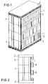
- FIGS. 1 and 2 The overall structure of a cabinet which is constructed in accordance with the present invention results from FIGS. 1 and 2.
- the cabinet essentially consists of stacked subracks 1.
- the entirety of the subracks is closed by a head part or by a cover 2 and a foot part or bottom part 3.
- the individual subracks are delimited by side parts 4 and rear wall covers 5.
- the front end is formed by module covers 6, which are designed differently depending on the size of the modules and the task of the modules.
- the individual subracks 1 can be provided on the front top and bottom with cover panels 8, behind which there are, for. B. assembly safeguards against unauthorized insertion and removal of the individual modules.
- fans can be integrated within the base parts 3 or the head parts 2.
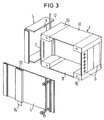
- FIG. 3 shows details of a rack 1 of a cabinet according to the invention.
- the rack 1 consists of essentially from the two side parts 4, which are connected by cross bars 10. Different assemblies with corresponding assembly covers 6 can be inserted between the upper and lower cross bars 10 of a subrack 1. These modules are contacted by means of plug connectors with a rear wall wiring 7.
- the side parts which also serve as cabinet cladding, have pegs 14 on their lower edges, which engage in corresponding receiving openings 13, which are arranged on their upper edges and correspond in contour to the pegs and are arranged in alignment with them, and thus an exact stacking of the Enable subracks.
- the rear wall cover 5 of the individual subracks 1 is mounted at a distance from the rear wall wiring 7 of the subrack 1. In this way it is possible to wire the modules and the subracks to one another within the closed cabinet.
- the individual subracks 1 are shielded at the top and bottom by means of shield plates 11.
- the module covers 6, the side parts 4 and the rear wall cover 5 are integrated in the shield concept.
Abstract
Description
Die Erfindung betrifft einen Schrank zur Aufnahme von mehreren elektrischen Baugruppenträgern mit unterschiedlichen Baugruppen, die jeweils innerhalb eines Baugruppenträgers über Rückwandsteckerleisten sowie eine Rückwandverdrahtung und mit Baugruppen anderer Baugruppenträger über Steckerkabel verbunden sind, wobei innerhalb der Baugruppenträger unterschiedlich breite Baugruppen einsetzbar sind.The invention relates to a cabinet for accommodating a plurality of electrical subracks with different assemblies, each of which is connected within a subrack via rear-wall connector strips and a backplane wiring and with assemblies of other subracks via plug cables, modules of different widths being usable within the subrack.
Ein derartiger Schrank ist z. B. aus der DE-OS 28 42 060 bekannt. Bei diesem Schrank sind die Baugruppenträger innerhalb eines Gestellrahmens, der aus senkrechten seitlichen Gestellholmen sowie aus waagerechten oberen und unteren Gestellholmen besteht, angeordnet. Der Nachteil dieses bekannten Schranks besteht darin, daß ein Gestellrahmen bestimmter Größe vorgeleistet werden muß, auch wenn dieser nicht voll bestückt wird. Daher müssen bei diesem bekannten Schrank in der Regel durch die Vorgabe einer bestimmten Schrankgröße unnötig große Vorleistungen erbracht werden.Such a cabinet is e.g. B. from DE-OS 28 42 060 known. In this cabinet, the subracks are arranged within a frame, which consists of vertical side frame bars and horizontal upper and lower frame bars. The disadvantage of this known cabinet is that a frame of a certain size must be provided, even if it is not fully equipped. Therefore, in this known cabinet usually unnecessarily large upfront investments must be made by specifying a certain cabinet size.
Aus dem deutschen Gebrauchsmuster 85 09 591 ist nun ein Schrank bekannt, welcher unterschiedlich auftretenden Bestückungswünschen angepaßt werden kann. Dazu besteht dieser Schrank aus mehreren einzelnen selbständigen stapelbaren Baugruppenträgern. Nachteilig bei diesem bekannten Schrank ist, daß je nach Anzahl der verwendeten und übereinander gestapelten Baugruppenträger unterschiedlich große Seitenteile, Rückwände und Türen verwendet werden müssen.From the German utility model 85 09 591 a cabinet is now known, which can be adapted to different assembly requirements. For this purpose, this cabinet consists of several individual, stackable subracks. A disadvantage of this known cabinet is that, depending on the number of subracks used and stacked one above the other, differently sized side parts, rear walls and doors have to be used.
Aufgabe der vorliegenden Erfindung ist es, einen Schrank der eingangs genannten Art anzugeben, welcher bezüglich der unterschiedlich verlangten Größenordnungen beim Aufbau eine noch größere Flexibilität ohne irgendwelche Vorleistungen bietet.The object of the present invention is to provide a cupboard of the type mentioned at the outset, which offers even greater flexibility with regard to the different sizes required in the construction without any preliminary work.
Diese Aufgabe wird für einen Schrank der obengenannten Art erfindungsgemäß dadurch gelöst, daß der Schrank aus einem oder mehreren stapelbaren Baugruppenträgern sowie einem Boden- und einem Kopfteil besteht, daß die einzelnen Baugruppenträger als Außenwand ausgebildete Seitenteile und eine Rückwandabdeckung aufweisen, wobei die Seitenteile an den Unterkanten mit Zapfen und an den Oberkanten mit entsprechenden Aufnahmeöffnungen, die konturmäßig mit den Zapfen übereinstimmen und fluchtend zu den Zapfen angeordnet sind, versehen sind.This object is achieved according to the invention for a cabinet of the type mentioned above in that the cabinet consists of one or more stackable subracks and a base and a head part, that the individual subracks have side parts designed as an outer wall and a rear wall cover, the side parts on the lower edges are provided with pegs and on the upper edges with corresponding receiving openings which correspond in shape to the pegs and are aligned with the pegs.
Der Vorteil des erfindungsgemäßen Schranks besteht darin, daß Vorleistungen nur für die gewünschte Größe des Schranks geleistet werden müssen, und daß der Schrank anschließend je nach Wunsch beliebig erweiterbar ist, ohne daß bestimmte vorher verwendete Teile nicht mehr benutzt werden können. Durch die Zuordnung der Verkleidungsteile zu den einzelnen stapelbaren Baugruppenträgern werden also unnötige Vorleistungen bei größerer Flexibilität in der Erstellung der Schränke vermieden. Dabei wird die Vorderseite des Schranks durch die Blenden der einzelnen Baugruppen bzw. durch entsprechende Deckblenden gebildet.The advantage of the cabinet according to the invention is that advance payments only have to be made for the desired size of the cabinet, and that the cabinet can then be expanded as desired, without certain previously used parts no longer being able to be used. By assigning the cladding parts to the individual stackable subracks, unnecessary preliminary work with greater flexibility in the creation of the cabinets is avoided. The front of the cabinet is formed by the panels of the individual modules or by appropriate cover panels.
Eine zweckmäßige Ausgestaltung des erfindungsgemäßen Schranks ist dadurch gekennzeichnet, daß die Rückwandabdeckung mit Abstand zu den Querholmen der Baugruppenträger angebracht ist. Auf diese Weise kann die Verkabelung des Schranks innerhalb des Schrankraumes erfolgen.An expedient embodiment of the cabinet according to the invention is characterized in that the rear wall cover is mounted at a distance from the cross bars of the subrack. In this way, the cabling of the cabinet can be done within the cabinet room.
Eine andere zweckmäßige Ausgestaltung des erfindungsgemäßen Schranks ist dadurch gekennzeichnet, daß das Boden- und/oder Kopfteil Lüfter enthalten. Dadurch kann in jeder Ausbaustufe des erfindungsgemäßen Schranks für eine ausreichende Belüftung der einzelnen Baugruppen gesorgt werden.Another useful embodiment of the cabinet according to the invention is characterized in that the bottom and / or head part contain fans. As a result, adequate ventilation of the individual assemblies can be ensured in each expansion stage of the cabinet according to the invention.
Nachfolgend wird die Erfindung anhand eines in der Zeichnung dargestellten Ausführungsbeispiels näher erläutert.The invention is explained in more detail below on the basis of an exemplary embodiment shown in the drawing.
Es zeigen
- FIG 1
- eine perspektivische Ansicht eines Schranks gemäß der vorliegenden Erfindung mit vier übereinander gestapelten Baugruppenträgern sowie eine Kopf- und einem Fußteil,
- FIG 2
- eine Seitenansicht eines Schranks gemäß der vorliegenden Erfindung mit drei übereinander angeordneten Baugruppenträgern und einem Kopf- sowie einem Fußteil, und
- FIG 3
- eine perspektivische Teildarstellung eines Baugruppenrahmens eines Schrankes gemäß der vorliegenden Erfindung.
- FIG. 1
- 2 shows a perspective view of a cabinet according to the present invention with four subracks stacked one on top of the other and a head part and a foot part,
- FIG 2
- a side view of a cabinet according to the present invention with three superposed subracks and a head and a foot part, and
- FIG 3
- a partial perspective view of an assembly frame of a cabinet according to the present invention.
Der Gesamtaufbau eines Schranks, der gemäß der vorliegenden Erfindung aufgebaut ist, ergibt sich aus den FIG 1 und 2. Der Schrank besteht im wesentlichen aus übereinandergestapelten Baugruppenträgern 1. Abgeschlossen wird die Gesamtheit der Baugruppenträger durch ein Kopfteil bzw. durch einen Deckel 2 und ein Fußteil bzw. Bodenteil 3. Die einzelnen Baugruppenträger sind begrenzt von Seitenteilen 4 und Rückwandabdeckungen 5. Den vorderen Abschluß bilden Baugruppenblenden 6, welche je nach Größe der Baugruppen und je nach Aufgabe der Baugruppen unterschiedlich gestaltet sind. Weiterhin können die einzelnen Baugruppenträger 1 an der Vorderseite oben und unten mit Deckblenden 8 versehen sein, hinter denen sich z. B. Baugruppensicherungen gegen unbefugtes Stecken und Ziehen der einzelnen Baugruppen befinden.The overall structure of a cabinet which is constructed in accordance with the present invention results from FIGS. 1 and 2. The cabinet essentially consists of stacked
Zur besseren Wärmeabfuhr können innerhalb der Bodenteile 3 bzw. der Kopfteile 2 Lüfter integriert werden.For better heat dissipation, fans can be integrated within the
Details eines Baugruppenträgers 1 eines erfindungsgemäßen Schrankes zeigt die FIG 3. Der Baugruppenträger 1 besteht im wesentlichen aus den beiden Seitenteilen 4, die durch Querholme 10 miteinander verbunden sind. Zwischen den oberen und unteren Querholmen 10 eines Baugruppenträgers 1 können unterschiedliche Baugruppen mit entsprechenden Baugruppenblenden 6 eingeschoben werden. Diese Baugruppen werden mittels Steckverbinder mit einer Rückwandverdrahtung 7 kontaktiert. Die Seitenteile, welche gleichzeitig als Schrankverkleidung dienen, weisen an ihren Unterkanten Zapfen 14 auf, die in entsprechende Aufnahmeöffnungen 13, die an ihren Oberkanten angeordnet sind und konturmäßig mit den Zapfen übereinstimmen und mit diesen fluchtend angeordnet sind, eingreifen, und somit ein exaktes Stapeln der Baugruppenträger ermöglichen. Hierbei besteht die Möglichkeit, die Zapfen und die entsprechenden Aufnahmeöffnungen 13 sowie die Schrauben, die zur Befestigung der Seitenteile 4 mit den Querholmen 10 dienen, mittels einer Schraubenverkleidung auf ästhetische Weise zu verkleiden. Die Rückwandabdeckung 5 der einzelnen Baugruppenträger 1 ist mit Abstand von der Rückwandverdrahtung 7 der Baugruppenträger 1 angebracht. Auf diese Weise ist innerhalb des geschlossenen Schrankes eine Verdrahtung der Baugruppen sowie der Baugruppenträger untereinander möglich.FIG. 3 shows details of a
Die einzelnen Baugruppenträger 1 sind oben und unten mittels Schirmblechen 11 abgeschirmt. Um eine 100%ige Schirmung zu erreichen, sind die Baugruppenblenden 6, die Seitenteile 4 sowie die Rückwandabdeckung 5 in das Schirmkonzept integriert.The
Claims (3)
dadurch gekennzeichnet,
daß der Schrank aus einem oder mehreren stapelbaren Baugruppenträgern (1) sowie einem Boden- (3) und einem Kopfteil (2) besteht, daß die einzelnen Baugruppenträger (1) als Außenwand ausgebildete Seitenteile (4) und eine Rückwandabdeckung (5) aufweisen, wobei die Seitenteile (4) an den Unterkanten mit Zapfen (14) und an den Oberkanten mit entsprechenden Aufnahmeöffnungen (13), die konturmäßig mit den Zapfen (14) übereinstimmen und fluchtend zu den Zapfen (14) angeordnet sind, versehen sind.Cabinet for accommodating several electrical subracks with different subassemblies, each of which is connected within a subrack via backplane connector strips as well as backplane wiring and with subassemblies of other subracks via plug cables, with subracks of different widths being usable within the subrack,
characterized,
that the cabinet consists of one or more stackable subracks (1) and a base (3) and a head part (2), that the individual subracks (1) have side parts (4) designed as an outer wall and a rear wall cover (5), whereby the side parts (4) are provided on the lower edges with pegs (14) and on the upper edges with corresponding receiving openings (13) which match the contours of the pegs (14) and are aligned with the pegs (14).
dadurch gekennzeichnet,
daß die Rückwandabdeckung (5) mit Abstand zu den Querholmen (10) der Baugruppenträger (1) angebracht ist.Cabinet according to claim 1,
characterized,
that the rear wall cover (5) is attached at a distance to the cross bars (10) of the subrack (1).
dadurch gekennzeichnet,
daß das Boden- (3) und/oder Kopfteil (2) Lüfter enthalten.Cabinet according to claim 1,
characterized,
that the bottom (3) and / or head part (2) contain fans.
Applications Claiming Priority (2)
| Application Number | Priority Date | Filing Date | Title |
|---|---|---|---|
| DE9012049U | 1990-08-21 | ||
| DE9012049U DE9012049U1 (en) | 1990-08-21 | 1990-08-21 |
Publications (2)
| Publication Number | Publication Date |
|---|---|
| EP0471995A2 true EP0471995A2 (en) | 1992-02-26 |
| EP0471995A3 EP0471995A3 (en) | 1992-09-09 |
Family
ID=6856707
Family Applications (1)
| Application Number | Title | Priority Date | Filing Date |
|---|---|---|---|
| EP19910112359 Withdrawn EP0471995A3 (en) | 1990-08-21 | 1991-07-23 | Housing for receiving card frames |
Country Status (3)
| Country | Link |
|---|---|
| US (1) | US5229924A (en) |
| EP (1) | EP0471995A3 (en) |
| DE (1) | DE9012049U1 (en) |
Families Citing this family (5)
| Publication number | Priority date | Publication date | Assignee | Title |
|---|---|---|---|---|
| US5396575A (en) * | 1992-12-18 | 1995-03-07 | Raynet Corporation | Sealed optical fiber closures |
| US5381314A (en) * | 1993-06-11 | 1995-01-10 | The Whitaker Corporation | Heat dissipating EMI/RFI protective function box |
| KR0148533B1 (en) * | 1995-09-19 | 1998-11-02 | 김광호 | Self-locking device for communication transmission equipment |
| CN201229536Y (en) * | 2008-07-03 | 2009-04-29 | 鸿富锦精密工业(深圳)有限公司 | Computer machine box |
| CN101931828B (en) * | 2009-06-12 | 2013-01-30 | 华为技术有限公司 | Back plate and communication equipment |
Citations (4)
| Publication number | Priority date | Publication date | Assignee | Title |
|---|---|---|---|---|
| US3772572A (en) * | 1972-05-31 | 1973-11-13 | J Marquette | Plug-in equipment storage unit |
| DE2910808B1 (en) * | 1979-03-20 | 1980-01-10 | Tekade Felten & Guilleaume | Frame for communication technology |
| DE8509591U1 (en) * | 1985-03-29 | 1985-05-15 | Siemens AG, 1000 Berlin und 8000 München | Frame for holding electrical assemblies |
| US4938351A (en) * | 1989-06-20 | 1990-07-03 | International Business Machines Corporation | Modular electrical component packaging system |
Family Cites Families (6)
| Publication number | Priority date | Publication date | Assignee | Title |
|---|---|---|---|---|
| DE2842060A1 (en) * | 1978-09-27 | 1980-04-10 | Siemens Ag | Rack with frame built of bars - consists of only vertical side bars and horizontal top and bottom bars, with subassembly units fastened to vertical bars |
| DE7834992U1 (en) * | 1978-11-24 | 1980-05-08 | Siemens Ag, 1000 Berlin Und 8000 Muenchen | DEVICE FOR SEVERAL SOUND AND / OR HEAT-RELEASING MACHINES TO BE SET UP IN A WORKPLACE |
| DE3045326C2 (en) * | 1980-12-02 | 1982-10-21 | Autz & Hermann, 6900 Heidelberg | Heat exchanger used for dust-free cooling of a switch cabinet |
| US4477862A (en) * | 1982-05-19 | 1984-10-16 | Gould Inc. | Backplane connector |
| US4555744A (en) * | 1984-08-28 | 1985-11-26 | Plug-In Storage Systems, Inc. | Storage cabinet |
| US4967311A (en) * | 1987-07-22 | 1990-10-30 | Tandem Computers Incorporated | Electronic module interconnection system |
-
1990
- 1990-08-21 DE DE9012049U patent/DE9012049U1/de not_active Expired - Lifetime
-
1991
- 1991-07-23 EP EP19910112359 patent/EP0471995A3/en not_active Withdrawn
- 1991-08-09 US US07/743,234 patent/US5229924A/en not_active Expired - Fee Related
Patent Citations (4)
| Publication number | Priority date | Publication date | Assignee | Title |
|---|---|---|---|---|
| US3772572A (en) * | 1972-05-31 | 1973-11-13 | J Marquette | Plug-in equipment storage unit |
| DE2910808B1 (en) * | 1979-03-20 | 1980-01-10 | Tekade Felten & Guilleaume | Frame for communication technology |
| DE8509591U1 (en) * | 1985-03-29 | 1985-05-15 | Siemens AG, 1000 Berlin und 8000 München | Frame for holding electrical assemblies |
| US4938351A (en) * | 1989-06-20 | 1990-07-03 | International Business Machines Corporation | Modular electrical component packaging system |
Also Published As
| Publication number | Publication date |
|---|---|
| EP0471995A3 (en) | 1992-09-09 |
| US5229924A (en) | 1993-07-20 |
| DE9012049U1 (en) | 1990-10-25 |
Similar Documents
| Publication | Publication Date | Title |
|---|---|---|
| EP0886993B1 (en) | Module of an electrical device | |
| DE3608046C2 (en) | ||
| EP0898444B1 (en) | Cabinet for electrical equipment | |
| EP0316821B1 (en) | Housing for containing electrical assemblies | |
| EP0262482A1 (en) | Housing for receiving card frames | |
| EP0471995A2 (en) | Housing for receiving card frames | |
| EP0415246A2 (en) | Electronic rack | |
| EP0596349B1 (en) | Electric rack | |
| EP0458832B1 (en) | Appliance system comprising a first electrical appliance and at least a second electrical appliance coupled thereto | |
| DE2740971C2 (en) | Frame of the vertical construction | |
| EP0089401A2 (en) | Forcibly ventilated equipment carrier | |
| DE2515978B2 (en) | ASSEMBLY SYSTEM FOR COMPONENT CARRIER | |
| EP0584658A2 (en) | Distributor for EMI shielded cabinets | |
| DE69633107T2 (en) | Junction box with means for the mechanical guidance of cables | |
| EP0560067B1 (en) | Housing system | |
| EP0859974B1 (en) | Computer housing | |
| DE1094508B (en) | Housing for program-controlled accounting or calculating machines | |
| DE4123504C2 (en) | computer | |
| EP0450384A2 (en) | Modular computer enclosure | |
| DE8509591U1 (en) | Frame for holding electrical assemblies | |
| DE1145678B (en) | Device for housing components for television technology | |
| DE4010545A1 (en) | Modular computer housing - has basic housing into which are inserted individual modules which can be tested discretely, e.g. CPU, ventilator unit modules | |
| DE1540561C3 (en) | Low voltage distribution system | |
| EP0701191A1 (en) | Computer enclosure | |
| CH403002A (en) | Arrangement for holding and electrical connection of plastic plates with printed or etched circuit |
Legal Events
| Date | Code | Title | Description |
|---|---|---|---|
| PUAI | Public reference made under article 153(3) epc to a published international application that has entered the european phase |
Free format text: ORIGINAL CODE: 0009012 |
|
| AK | Designated contracting states |
Kind code of ref document: A2 Designated state(s): AT DE FR GB IT SE |
|
| PUAL | Search report despatched |
Free format text: ORIGINAL CODE: 0009013 |
|
| AK | Designated contracting states |
Kind code of ref document: A3 Designated state(s): AT DE FR GB IT SE |
|
| 17P | Request for examination filed |
Effective date: 19921023 |
|
| 17Q | First examination report despatched |
Effective date: 19931202 |
|
| STAA | Information on the status of an ep patent application or granted ep patent |
Free format text: STATUS: THE APPLICATION HAS BEEN WITHDRAWN |
|
| 18W | Application withdrawn |
Withdrawal date: 19940407 |