EP0470925A1 - Dilatation catheter - Google Patents
Dilatation catheter Download PDFInfo
- Publication number
- EP0470925A1 EP0470925A1 EP91810500A EP91810500A EP0470925A1 EP 0470925 A1 EP0470925 A1 EP 0470925A1 EP 91810500 A EP91810500 A EP 91810500A EP 91810500 A EP91810500 A EP 91810500A EP 0470925 A1 EP0470925 A1 EP 0470925A1
- Authority
- EP
- European Patent Office
- Prior art keywords
- section
- lumen
- dilatation catheter
- sections
- shaft
- Prior art date
- Legal status (The legal status is an assumption and is not a legal conclusion. Google has not performed a legal analysis and makes no representation as to the accuracy of the status listed.)
- Granted
Links
Images

Classifications
-
- A—HUMAN NECESSITIES
- A61—MEDICAL OR VETERINARY SCIENCE; HYGIENE
- A61M—DEVICES FOR INTRODUCING MEDIA INTO, OR ONTO, THE BODY; DEVICES FOR TRANSDUCING BODY MEDIA OR FOR TAKING MEDIA FROM THE BODY; DEVICES FOR PRODUCING OR ENDING SLEEP OR STUPOR
- A61M25/00—Catheters; Hollow probes
- A61M25/10—Balloon catheters
- A61M25/104—Balloon catheters used for angioplasty
-
- A—HUMAN NECESSITIES
- A61—MEDICAL OR VETERINARY SCIENCE; HYGIENE
- A61M—DEVICES FOR INTRODUCING MEDIA INTO, OR ONTO, THE BODY; DEVICES FOR TRANSDUCING BODY MEDIA OR FOR TAKING MEDIA FROM THE BODY; DEVICES FOR PRODUCING OR ENDING SLEEP OR STUPOR
- A61M25/00—Catheters; Hollow probes
- A61M25/0009—Making of catheters or other medical or surgical tubes
- A61M25/0014—Connecting a tube to a hub
Definitions
- the invention relates to a dilatation catheter according to the preamble of independent claim 1.
- Catheters of this type were first developed by A. Grüntzig for percutaneously transluminal recanalization of chronic arterial occlusions and have become increasingly important since then.
- the catheter system used for this purpose generally consists of a guide wire, a dilatation catheter with an at least two-lumen shaft and a dilatation balloon arranged distally thereon, and a guide catheter. Through the latter, the guide wire and on this the dilatation catheter are advanced until the dilatation balloon is in the constriction. The balloon is now dilated with liquid and the arteriosclerotic material is pressed radially against and into the vessel wall, so that after the catheter has been removed, the treated area for the vascular fluid is again permeable.
- the shaft of the dilatation catheter usually consists essentially of two coaxial tube pieces, the inner tube receiving the guide wire and an intermediate space between the two tube pieces forming the lumen for the liquid for dilating the balloon.
- EP-A-0 277 368 has disclosed a two-lumen dilatation catheter in which the shaft is made from several areas of different stiffness. This is to achieve optimal flexibility and stability at different locations along the catheter.
- shaft sections are made of different materials and these are thermoplastic bonded together.
- a dilatation balloon in which the two coaxial tube pieces of the shaft are connected with webs directly behind the balloon. These webs transmit the axial thrust from the outer tube to the inner tube and are intended to prevent the above-mentioned upsetting of the shaft when treating severely stenosed vessels. Such webs make the manufacture of the catheter much more difficult and more expensive and narrow the lumen for the passage of the pressure fluid.
- the invention has for its object to provide a dilatation catheter of the type mentioned, which avoids the above-mentioned difficulties and which is particularly suitable for the treatment of severely stenosed vessel sections which are located in or after a bend in the vessel.
- the proximal section of the shaft seen in longitudinal section, has four walls, while the distal section requires only three walls for the two lumens. With the same or similar plastic, the proximal section is stiffer than the distal section.
- the length of the more flexible distal section is preferably adapted to the length of the curved vessel section. If the dilatation balloon is inserted into the constriction, the more flexible distal section runs in the curved area of the vessel and the stiffer proximal section in the largely straight area of the vessel. In the case of a coronary stenosis, for example, the distal section is 15-25 cm long and the proximal section is approximately 110 cm long. The longer proximal section ensures a low-friction sliding of the guide wire due to the round cross-section of the inner tube piece. The distal section prevents compression of the balloon, since in this section the walls of the two lumens are not separated and therefore cannot move against one another in the longitudinal direction.
- the two sections overlap at their connection points and are welded to one another on the adjacent surfaces.
- the sections consist of a thermoplastic, for example a polyamide, polyurethane, polyvinyl chloride, polyester, polyethylene, or another suitable plastic. Both sections can consist of the same plastic or of different plastics that can be welded together.
- At least one section has a reduced wall thickness at the end connected to the other section, it can largely be prevented that the shaft at its connection point is harder than in other areas.
- the reduced wall thickness is advantageously achieved by stretching the relevant end (s).
- the dilatation catheter 1 shown in FIG. 1 is inserted through a guide catheter 19 (FIG. 6) into a blood vessel 17 until the dilatation balloon 8 is in front of the constriction 18 to be treated. With the aid of a guide wire 7, the balloon 8 is pushed into the passage of the constriction 18, as shown in FIG. 6.
- the guide wire 7 can be displaced in the longitudinal direction in a continuous first lumen 11 of the dilatation catheter 1.
- the interior of the balloon 8 is connected via a second lumen 12 to a pressure suction device, not shown here, which is connected to a connection 6 of a connecting piece 4.
- a second connection 5 of the connecting piece 4 serves for the insertion and sealing of the guide wire 7.
- the first lumen 11 of the dilatation catheter 1 is thus connected to the connection 5 and the second lumen 12 to the connection 6.
- FIG. 7 shows the generally known balloon 8, which is connected via an opening 15 to the second lumen 12 and via this to the connection 6.
- the balloon 8 can be folded for its introduction into the vessel 17 and dilated for the treatment of the stenosis 18.
- the guide wire 7 can be advanced beyond the dilatation balloon 8 through an opening 16 at its distal end. As is known, it is particularly flexible at its distal end and yet torsionally rigid.
- the shaft 3 is made up of a proximal section 3a and a distal section 3b. These sections 3a and 3b are produced separately and connected to one another at the connection point 13. Like Figures 3 and 4 show, the cross sections of the two sections 3a and 3b are different.
- the proximal section 3a consists of two coaxial tube pieces 9 and 10, the inner tube piece 10 forming a lumen 11a for the guide wire 7.
- the space between the tube pieces 9 and 10 forms a lumen 12a, in which pressure fluid can circulate between the balloon 8 and the pressure suction pump.
- the tube pieces 9 and 10 have a circular cross section and consist of a thermoplastic.
- the shaft section 3a is fixedly connected to the connecting piece 4 in a known manner.
- the shaft section 3b consists of a two-lumen, extruded tube piece 14, which is connected to the balloon 8 in a known manner.
- a first approximately circular lumen 11b serves to receive the guide wire 7 and a second crescent-shaped lumen 12b serves to receive the pressure fluid. Both lumens are separated from one another by a partition wall 14c formed on section 3b.
- the sections 3a and 3b are connected to one another in accordance with FIG. 2 such that the lumens 11a and 11b form the first lumen 11 and the lumens 12a and 12b form the lumen 12.
- the lumens 11 and 12 are thus also completely separated from one another at the connection point 13.
- the tube piece 9 is preferably stretched in the longitudinal direction at the end to be connected and has an area 9a with reduced wall thickness. This avoids that the outer diameter of the shaft 3 at the connection point 13 is significantly larger than outside of this area.
- the two hose sections 3a and 3b are preferably welded together.
- the outer surface 14a of the hose section 14 is preferably welded to the inner surface 9b of the hose section 9 and the outside 10a of the hose section 10 to the inside 14b of the hose section 14.
- An embodiment is also possible in which the tube piece 14 has a reduced wall thickness at the end to be connected. This reduced wall thickness can also be achieved here, for example, by grinding the tube piece 14 on the outside 14a.
- An embodiment is also conceivable in which the two sections 3a and 3b are glued together at the overlapping region 13.
- the hose section 3a has greater rigidity than the hose section 3b.
- the main reason for the different stiffness is seen in the fact that the tube section 3a in the longitudinal section according to FIG. 2 consists of four wall areas and the section 3b only consists of three wall areas. The different stiffness is thus primarily caused by the different structures of the two sections 3a and 3b.
- the length of the more flexible section 3b is preferably adapted to the length of the arcuate section of the blood vessel 17 to be treated, as is shown schematically in FIG. 6.
- the vasoconstriction 18 is located here in the flow direction of the vascular fluid in or after a vascular bend 17b and this in turn connects to a largely straight vascular section 17a.
- the more flexible section 3b can easily follow the bend of the vessel 17 with little risk of injury. Since section 3b has the cross section shown in FIG. 4, compression of balloon 8 in the longitudinal direction is also not possible expect if the constriction 18 offers comparatively high resistance to displacement of the catheter.
- the guide wire 7 slides particularly easily in the stiff but largely straight section 3a, since the lumen 11a is largely circular. This can be further improved by suitable coatings on the guide wire 7 and the inside of the tube piece 10.
- the vascular course shown in FIG. 6 is typical in many treatment cases.
- An embodiment is also conceivable in which both sections 3a and 3b or one of these sections have more than two lumens.
- section 3b can be four-lumen.
Abstract
Description
Die Erfindung betrifft einen Dilatationskatheter nach dem Oberbegriff des unabhängigen Patentanspruchs 1. Katheter dieser Gattung sind von A. Grüntzig zur perkutan transluminalen Rekanalisation chronischer Arterienverschlüsse erstmals entwickelt worden und haben seither stetig an Bedeutung gewonnen. Das hierzu verwendete Kathetersystem besteht in der Regel aus einem Führungsdraht, einem Dilatationskatheter mit einem wenigstens zweilumigen Schaft und einem distal an diesem angeordneten Dilatationsballon sowie einem Führungskatheter. Durch den letzteren wird der Führungsdraht und auf diesem der Dilatationskatheter so weit vorgeschoben, bis der Dilatationsballon sich in der Verengung befindet. Mit Flüssigkeit wird der Ballon nun dilatiert und das arteriosklerotische Material radial gegen und in die Gefässwandung gepresst, so dass nach dem Entfernen des Katheters der behandelte Bereich für die Gefässflüssigkeit wieder durchgängig ist.The invention relates to a dilatation catheter according to the preamble of
Der Schaft des Dilatationskatheters besteht üblicherweise im wesentlichen aus zwei koaxialen Schlauchstücken, wobei der innere Schlauch den Führungsdraht aufnimmt und ein Zwischenraum zwischen den beiden Schlauchstücken das Lumen für die Flüssigkeit zum Dilatieren des Ballons bildet. Beim Vorschieben des Ballons in starke Verengungen wird infolge der vergleichsweise hohen axialen Kräfte der Ballon und der hinten mit diesem verbundene Schlauch gestaucht, was die Einführung des Ballons in die Verengung erschwert. Um dies zu vermeiden, wäre somit ein möglichst steifer Schaft erwünscht. Liegt die Verengung nach einer Gefässbiegung, so sollte hingegen der Schaft im vorderen Bereich möglichst flexibel sein, damit er mit möglichst geringer Reibung der Gefässbiegung folgen kann.The shaft of the dilatation catheter usually consists essentially of two coaxial tube pieces, the inner tube receiving the guide wire and an intermediate space between the two tube pieces forming the lumen for the liquid for dilating the balloon. When the balloon is pushed forward into severe constrictions, the relatively high axial forces cause the balloon and the hose connected to it to be compressed, which makes it more difficult to insert the balloon into the narrowing. To avoid this, a shaft that is as stiff as possible would be desirable. If the constriction is after a vessel bend, however, the shaft in the front area should be as flexible as possible so that it can follow the vessel bend with as little friction as possible.
Um diese Schwierigkeit zu vermeiden, ist durch die EP-A-0 277 368 ein zweilumiger Dilatationskatheter bekannt geworden, bei welchem der Schaft aus mehreren Bereichen unterschiedlicher Steifigkeit hergestellt ist. Damit soll entlang des Katheters an unterschiedlichen Stellen optimale Flexibilität und Stabilität erreicht werden. Dazu sind Schaftabschnitte aus unterschiedlichen Werkstoffen hergestellt und diese miteinander thermoplastisch verbunden.In order to avoid this difficulty, EP-A-0 277 368 has disclosed a two-lumen dilatation catheter in which the shaft is made from several areas of different stiffness. This is to achieve optimal flexibility and stability at different locations along the catheter. For this purpose, shaft sections are made of different materials and these are thermoplastic bonded together.
Weiter ist ein Dilatationsballon bekannt, bei dem die beiden koaxialen Schlauchstücke des Schaftes unmittelbar hinter dem Ballon mit Stegen verbunden sind. Diese Stege übertragen die axiale Schubkraft vom äusseren Schlauch auf den inneren Schlauch und sollen das oben genannte Stauchen des Schaftes bei der Behandlung stark stenosierter Gefässe verhindern. Solche Stege erschweren und verteuern die Herstellung des Katheters wesentlich und verengen das Lumen für den Durchlass der Druckflüssigkeit.Furthermore, a dilatation balloon is known in which the two coaxial tube pieces of the shaft are connected with webs directly behind the balloon. These webs transmit the axial thrust from the outer tube to the inner tube and are intended to prevent the above-mentioned upsetting of the shaft when treating severely stenosed vessels. Such webs make the manufacture of the catheter much more difficult and more expensive and narrow the lumen for the passage of the pressure fluid.
Der Erfindung liegt die Aufgabe zugrunde, einen Dilatationskatheter der genannten Gattung zu schaffen, der die oben genannten Schwierigkeiten vermeidet und der insbesondere auch zur Behandlung von stark stenosierten Gefässabschnitten geeignet ist, die sich in oder nach einer Gefässbiegung befinden.The invention has for its object to provide a dilatation catheter of the type mentioned, which avoids the above-mentioned difficulties and which is particularly suitable for the treatment of severely stenosed vessel sections which are located in or after a bend in the vessel.
Die Aufgabe wird durch die Erfindung gemäss Anspruch 1 gelöst.The object is achieved by the invention according to
Der proximale Abschnitt des Schaftes besitzt, im Längsschnitt gesehen, vier Wandungen, während der distale Abschnitt für die beiden Lumina lediglich drei Wandungen erfordert. Bei gleichem oder ähnlichem Kunststoff ist der proximale Abschnitt steifer als der distale Abschnitt.The proximal section of the shaft, seen in longitudinal section, has four walls, while the distal section requires only three walls for the two lumens. With the same or similar plastic, the proximal section is stiffer than the distal section.
Durch die Verwendung unterschiedlich steifer Kunststoffe kann der Unterschied in der Steifigkeit der beiden Abschnitte beinahe beliebig gewählt werden. Der flexiblere distale Abschnitt ist vorzugsweise in seiner Länge an die Länge des gebogenen Gefässabschnitts angepasst. Ist der Dilatationsballon in die Engstelle eingesetzt, so verläuft der flexiblere distale Abschnitt im gebogenen Bereich des Gefässes und der steifere proximale Abschnitt im weitgehend geraden Bereich des Gefässes. Bei einer koronaren Stenose ist der distale Abschnitt beispielsweise 15 - 25 cm und der proximale Abschnitt etwa 110 cm lang. Der längere proximale Abschnitt gewährleistet durch den runden Querschnitt des inneren Schlauchstücks ein reibungsarmes Gleiten des Führungsdrahtes. Der distale Abschnitt verhindert eine Stauchung des Ballons, da in diesem Abschnitt die Wandungen der beiden Lumina nicht getrennt sind, und sich diese somit in Längsrichtung nicht gegeneinander verschieben können.By using different rigid plastics, the difference in the stiffness of the two sections can be chosen almost arbitrarily. The length of the more flexible distal section is preferably adapted to the length of the curved vessel section. If the dilatation balloon is inserted into the constriction, the more flexible distal section runs in the curved area of the vessel and the stiffer proximal section in the largely straight area of the vessel. In the case of a coronary stenosis, for example, the distal section is 15-25 cm long and the proximal section is approximately 110 cm long. The longer proximal section ensures a low-friction sliding of the guide wire due to the round cross-section of the inner tube piece. The distal section prevents compression of the balloon, since in this section the walls of the two lumens are not separated and therefore cannot move against one another in the longitudinal direction.
Nach einer Weiterbildung der Erfindung überlappen sich die beiden Abschnitte an ihren Verbindungsstellen und sind an den anliegenden Flächen miteinander verschweisst. In diesem Fall bestehen die Abschnitte aus einem thermoplastischen Kunststoff, beispielsweise aus einem Polyamid, Polyurethan, Polyvinylchlorid, Polyester, Polyaethylen, oder einem anderen geeigneten Kunststoff. Beide Abschnitte können aus dem gleichen Kunststoff oder aus unterschiedlichen, miteinander verschweissbaren Kunststoffen bestehen.According to a development of the invention, the two sections overlap at their connection points and are welded to one another on the adjacent surfaces. In this case, the sections consist of a thermoplastic, for example a polyamide, polyurethane, polyvinyl chloride, polyester, polyethylene, or another suitable plastic. Both sections can consist of the same plastic or of different plastics that can be welded together.
Weist hierbei wenigstens ein Abschnitt an dem mit dem anderen Abschnitt verbundenen Ende eine verminderte Wandstärke auf, so lässt sich weitgehend verhindern, dass der Schaft an seiner genannten Verbindungsstelle härter ist als in anderen Bereichen. Die verminderte Wandstärke wird vorteilhafterweise durch eine Streckung des bzw. der betreffenden Enden erreicht.If at least one section has a reduced wall thickness at the end connected to the other section, it can largely be prevented that the shaft at its connection point is harder than in other areas. The reduced wall thickness is advantageously achieved by stretching the relevant end (s).
Ein Ausführungsbeispiel des erfindungsgemässen Dilatationskatheters wird nachfolgend anhand der Zeichnungen näher erläutert. Es zeigen:
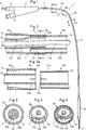
- Fig. 1 eine Ansicht eines erfindungsgemässen Dilatationskatheters,
- Fig. 2 einen Längsschnitt durch einen Abschnitt des Schaftes,
- Fig. 2a die Enden zweier Schaftabschnitte im Längsschnitt und vor dem Zusammenfügen dieser beiden Abschnitte,
- Fig. 3 ein querschnitt entlang der Linie III-III in Fig. 1,
- Fig. 4 ein querschnitt entlang der Linie IV-IV in Fig. 1,
- Fig. 5 ein querschnitt entlang der Linie V-V in Fig. 1 und 2,
- Fig. 6 im Längsschnitt ein Blutgefässegment mit einem eingeführten Dilatationskatheter, und
- Fig. 7 ein Längsschnitt durch das vordere Ende des Dilatationskatheters und durch das vordere Ende eines Führungsdrahtes.
- 1 is a view of a dilatation catheter according to the invention,
- 2 shows a longitudinal section through a section of the shaft,
- 2a the ends of two shaft sections in longitudinal section and before the joining of these two sections,
- 3 shows a cross section along the line III-III in FIG. 1,
- 4 shows a cross section along the line IV-IV in FIG. 1,
- 5 shows a cross section along the line VV in FIGS. 1 and 2,
- Fig. 6 in longitudinal section a blood vessel segment with an inserted dilatation catheter, and
- Fig. 7 is a longitudinal section through the front end of the dilatation catheter and through the front end of a guide wire.
Der in Fig. 1 gezeigte Dilatationskatheter 1 wird durch einen Führungskatheter 19 (Fig. 6) in ein Blutgefäss 17 eingeführt, bis sich der Dilatationsballon 8 vor der zu behandelnden Engstelle 18 befindet. Mit Hilfe eines Führungsdrahtes 7 wird der Ballon 8,wie in Fig. 6 gezeigt, in den Durchgang der Engstelle 18 eingeschoben. Der Führungsdraht 7 ist in einem durchgehenden ersten Lumen 11 des Dilatationskatheters 1 in Längsrichtung verschiebbar. Der Innenraum des Ballons 8 ist über ein zweites Lumen 12 mit einer hier nicht gezeigten Druck-Saugeinrichtung verbunden, die an einem Anschluss 6 eines Verbindungsstückes 4 angeschlossen ist. Ein zweiter Anschluss 5 des Verbindungsstückes 4 dient zur Einführung und Abdichtung des Führungsdrahtes 7. Das erste Lumen 11 des Dilatationskatheters 1 ist somit mit dem Anschluss 5 und das zweite Lumen 12 mit dem Anschluss 6 verbunden.The
Ein flexibler Schaft 3 ist an seinem distalen Ende mit dem Ballon 8 und an seinem proximalen Ende mit dem Verbindungsstück 4 verbunden. Die Figur 7 zeigt den allgemein bekannten Ballon 8, der über eine Oeffnung 15 mit dem zweiten Lumen 12 und über diesen mit dem Anschluss 6 verbunden ist. Mittels der genannten Druck-Saugeinrichtung kann der Ballon 8 zu seiner Einführung in das Gefäss 17 gefaltet und zur Behandlung der Stenose 18 dilatiert werden. Der Führungsdraht 7 kann wie in Fig.7 gezeigt, an seinem distalen Ende durch eine Oeffnung 16 über den Dilatationsballon 8 hinaus vorgeschoben werden. Er ist wie bekannt an seinem distalen Ende besonders flexibel und dennoch torsionssteif.A
Der Schaft 3 ist aus einem proximalen Abschnitt 3a und einem distalen Abschnitt 3b hergestellt. Diese Abschnitte 3a und 3b sind separat hergestellt und an der Verbindungsstelle 13 miteinander verbunden. Wie die Figuren 3 und 4 zeigen, sind die Querschnitte der beiden Abschnitte 3a und 3b verschieden. Der proximale Abschnitt 3a besteht aus zwei koaxialen Schlauchstücken 9 und 10, wobei das innere Schlauchstück 10 ein Lumen 11a für den Führungsdraht 7 bildet. Der Zwischenraum zwischen den Schlauchstücken 9 und 10 bildet ein Lumen 12a, in welchem Druckflüssigkeit zwischen dem Ballon 8 und der Druck-Saugpumpe zirkulieren kann. Die Schlauchstücke 9 und 10 besitzen einen kreisrunden Querschnitt und bestehen aus einem thermoplastischen Kunststoff. Der Schaftabschnitt 3a ist in bekannter Weise mit dem Verbindungsstück 4 fest verbunden.The
Der Schaft Abschnitt 3b besteht aus einem zweilumigen, extrudierten Schlauchstück 14, das in bekannter Weise mit dem Ballon 8 verbunden ist. Ein erstes annähernd kreisförmiges Lumen 11b dient zur Aufnahme des Führungsdrahtes 7 und ein zweites halbmondförmiges Lumen 12b dient zur Aufnahme der Druckflüssigkeit. Beide Lumen sind durch eine am Abschnitt 3b angeformte Trennwand 14c voneinander getrennt.The
Die Abschnitte 3a und 3b sind gemäss Fig. 2 derart miteinander verbunden, dass die Lumen 11a und 11b das erste Lumen 11 und die Lumen 12a und 12b das Lumen 12 bilden.The
Die Lumen 11 und 12 sind somit auch an der Verbindungsstelle 13 vollständig voneinander getrennt. Um die separat hergestellten Abschnitte 3a und 3b miteinander zu verbinden, werden diese zusammengeschoben, bis sich die entsprechenden Enden auf einer Länge von wenigen Millimetern überlappen. Wie die Fig. 2a zeigt, ist vorzugsweise das Schlauchstück 9 an dem zu verbindenden Ende in Längsrichtung gestreckt und weist einen Bereich 9a mit verminderter Wandstärke auf. Dadurch ist vermieden, dass der Aussendurchmesser des Schaftes 3 an der Verbindungsstelle 13 wesentlich grösser ist als ausserhalb dieses Bereiches.The
Im Bereich der Verbindungsstelle 13 sind die beiden Schlauchabschnitte 3a und 3b vorzugsweise miteinander verschweisst. Vorzugsweise ist die Aussenfläche 14a des Schlauchstücks 14 mit der Innenfläche 9b des Schlauchstückes 9 und die Aussenseite 10a des Schlauchstückes 10 mit der Innenseite 14b des Schlauchstückes 14 verschweisst. Möglich ist auch eine Ausführung, bei welcher das Schlauchstück 14 an dem zu verbindenden Ende eine verminderte Wandstärke aufweist. Diese verminderte Wandstärke kann hier beispielsweise auch durch Abschleifen des Schlauchstückes 14 an der Aussenseite 14a erfolgen. Denkbar ist auch eine Ausführung, bei welcher die beiden Abschnitte 3a und 3b am überlappenden Bereich 13 miteinander verklebt sind.In the area of the
Sind die Abschnitte 3a und 3b aus gleichem oder ähnlichem Kunststoff hergestellt und sind die Wandstärken annähernd gleich, so besitzt das Schlauchstück 3a eine grössere Steifigkeit als das Schlauchstück 3b. Der Hauptgrund der unterschiedlichen Steifigkeit wird darin gesehen, dass das Schlauchstück 3a im Längsschnitt gemäss Fig. 2 aus vier Wandbereichen und der Abschnitt 3b lediglich aus drei Wandbereichen besteht. Die unterschiedliche Steifigkeit ist somit in erster Linie durch die unterschiedlichen Strukturen der beiden Abschnitte 3a und 3b verursacht.If the
Die Länge des flexibleren Abschnittes 3b ist vorzugsweise an die Länge des bogenförmigen Abschnittes des zu behandelnden Blutgefässes 17 angepasst, wie dies in Fig. 6 schematisch gezeigt ist. Die Gefässverengung 18 befindet sich hier in Strömungsrichtung der Gefässflüssigkeit gesehen in oder nach einer Gefässbiegung 17b und diese wiederum schliesst an einen weitgehend geraden Gefässabschnitt 17a an. Bei der Einführung des Dilatationskatheters 1 in das Gefäss und insbesondere bei der Einführung des Ballones 8 in die Engstelle 18 kann der flexiblere Abschnitt 3b der Biegung des Gefässes 17 mit geringer Verletzungsgefahr leicht folgen. Da der Abschnitt 3b den in Fig. 4 gezeigten querschnitt aufweist, ist eine Stauchung des Ballones 8 in Längsrichtung auch dann nicht zu erwarten, wenn die Engstelle 18 einer Verschiebung des Katheters vergleichsweise hohen Widerstand bietet. In dem steifen aber weitgehend gerade verlaufenden Abschnitt 3a gleitet der Führungsdraht 7 besonders leicht, da das Lumen 11a weitgehend kreisrund ist. Dies kann durch geeignete Beschichtungen des Führungsdrahtes 7 und der Innenseite des Schlauchstückes 10 noch verbessert werden. Der in Fig. 6 gezeigte Gefässverlauf ist bei vielen Behandlungsfällen typisch. Denkbar ist auch eine Ausführung, bei welcher beide Abschnitte 3a und 3b oder einer dieser Abschnitte mehr als zweilumig sind. So kann beispielsweise der Abschnitt 3b vierlumig sein.The length of the more
Claims (7)
Applications Claiming Priority (2)
| Application Number | Priority Date | Filing Date | Title |
|---|---|---|---|
| CH259690 | 1990-08-09 | ||
| CH2596/90 | 1990-08-09 |
Publications (2)
| Publication Number | Publication Date |
|---|---|
| EP0470925A1 true EP0470925A1 (en) | 1992-02-12 |
| EP0470925B1 EP0470925B1 (en) | 1993-08-04 |
Family
ID=4237334
Family Applications (1)
| Application Number | Title | Priority Date | Filing Date |
|---|---|---|---|
| EP91810500A Expired - Lifetime EP0470925B1 (en) | 1990-08-09 | 1991-06-26 | Dilatation catheter |
Country Status (9)
| Country | Link |
|---|---|
| US (1) | US5209729A (en) |
| EP (1) | EP0470925B1 (en) |
| JP (1) | JP2501378B2 (en) |
| AT (1) | ATE92350T1 (en) |
| AU (1) | AU635148B2 (en) |
| CA (1) | CA2048557C (en) |
| DE (2) | DE9106499U1 (en) |
| DK (1) | DK0470925T3 (en) |
| ES (1) | ES2043463T3 (en) |
Cited By (1)
| Publication number | Priority date | Publication date | Assignee | Title |
|---|---|---|---|---|
| EP0537895B1 (en) * | 1991-09-16 | 1996-11-20 | Cook Incorporated | Angioplasty balloon catheter |
Families Citing this family (33)
| Publication number | Priority date | Publication date | Assignee | Title |
|---|---|---|---|---|
| DE59206773D1 (en) * | 1991-06-03 | 1996-08-22 | Schneider Europ Ag | Catheter system for mechanical dilation of coronary stenoses |
| EP0546221B1 (en) * | 1991-12-11 | 1995-02-15 | Schneider (Europe) Ag | Balloon catheter |
| US5649909A (en) * | 1992-04-06 | 1997-07-22 | Scimed Life Systems, Inc. | Variable stiffness multi-lumen catheter |
| US5261879A (en) * | 1992-09-03 | 1993-11-16 | Scimed Life Systems, Inc. | Coaxial/side-by-side lumen perfusion dilatation catheter |
| US5395336A (en) * | 1993-04-26 | 1995-03-07 | Mallinckrodt Medical, Inc. | Method for joining portions of a inflation/expansion catheter and a catheter so formed |
| US5921957A (en) * | 1994-07-12 | 1999-07-13 | Scimed Life Systems, Inc. | Intravascular dilation catheter |
| US5569197A (en) * | 1994-12-21 | 1996-10-29 | Schneider (Usa) Inc | Drug delivery guidewire |
| ATE197760T1 (en) | 1995-06-29 | 2000-12-15 | Schneider Europ Gmbh | MEDICAL DEVICE FOR MEASUREMENT OF PRESSURE IN A BLOOD VESSEL |
| US5556382A (en) * | 1995-08-29 | 1996-09-17 | Scimed Life Systems, Inc. | Balloon perfusion catheter |
| JPH09129848A (en) * | 1995-11-06 | 1997-05-16 | Mitsubishi Electric Corp | Manufacture of semiconductor device having capacitor |
| US5690642A (en) | 1996-01-18 | 1997-11-25 | Cook Incorporated | Rapid exchange stent delivery balloon catheter |
| EP0850654A1 (en) | 1996-12-20 | 1998-07-01 | Schneider (Usa) Inc. | Implantable device sensing catheter |
| US6217549B1 (en) | 1997-02-28 | 2001-04-17 | Lumend, Inc. | Methods and apparatus for treating vascular occlusions |
| US6010449A (en) * | 1997-02-28 | 2000-01-04 | Lumend, Inc. | Intravascular catheter system for treating a vascular occlusion |
| US5968064A (en) * | 1997-02-28 | 1999-10-19 | Lumend, Inc. | Catheter system for treating a vascular occlusion |
| US6120516A (en) * | 1997-02-28 | 2000-09-19 | Lumend, Inc. | Method for treating vascular occlusion |
| US6508825B1 (en) | 1997-02-28 | 2003-01-21 | Lumend, Inc. | Apparatus for treating vascular occlusions |
| WO1998041277A1 (en) * | 1997-03-19 | 1998-09-24 | Microvena Corporation | Improved multi-lumen catheter |
| US6217527B1 (en) * | 1998-09-30 | 2001-04-17 | Lumend, Inc. | Methods and apparatus for crossing vascular occlusions |
| US6398798B2 (en) | 1998-02-28 | 2002-06-04 | Lumend, Inc. | Catheter system for treating a vascular occlusion |
| US20020007145A1 (en) | 1998-10-23 | 2002-01-17 | Timothy Stivland | Catheter having improved bonding region |
| DE20009204U1 (en) * | 2000-05-22 | 2000-08-17 | Jomed Gmbh | Stent implantation catheter assembly |
| WO2002032330A2 (en) * | 2000-10-16 | 2002-04-25 | Lumend, Inc. | Catheter for treating a vascular occlusion |
| AU2002235159A1 (en) * | 2000-12-05 | 2002-06-18 | Lumend, Inc. | Catheter system for vascular re-entry from a sub-intimal space |
| US20020143358A1 (en) * | 2001-02-13 | 2002-10-03 | Domingo Nicanor A. | Method and apparatus for micro-dissection of vascular occlusions |
| DE602004020449D1 (en) | 2003-02-26 | 2009-05-20 | Boston Scient Ltd | BALLOON CATHETER |
| AU2004255154B2 (en) * | 2003-06-10 | 2009-08-20 | Lumend, Inc. | Catheter systems and methods for crossing vascular occlusions |
| US8535344B2 (en) | 2003-09-12 | 2013-09-17 | Rubicon Medical, Inc. | Methods, systems, and devices for providing embolic protection and removing embolic material |
| US7699865B2 (en) * | 2003-09-12 | 2010-04-20 | Rubicon Medical, Inc. | Actuating constraining mechanism |
| US7815624B2 (en) * | 2004-05-18 | 2010-10-19 | Boston Scientific Scimed, Inc. | Medical devices and methods of making the same |
| US9480589B2 (en) * | 2005-05-13 | 2016-11-01 | Boston Scientific Scimed, Inc. | Endoprosthesis delivery system |
| DE102013225154A1 (en) * | 2013-12-06 | 2015-06-11 | Raumedic Ag | Catheter tube system and method of making a catheter tube system |
| EP3272384A4 (en) * | 2015-03-20 | 2018-11-14 | Terumo Kabushiki Kaisha | Catheter and catheter manufacturing method |
Citations (2)
| Publication number | Priority date | Publication date | Assignee | Title |
|---|---|---|---|---|
| US4705501A (en) * | 1982-04-12 | 1987-11-10 | Regents Of The University Of Minnesota | Bi-directional, anti-reflux vascular access system |
| EP0368523A2 (en) * | 1988-11-10 | 1990-05-16 | C.R. Bard, Inc. | Balloon dilatation catheter with integral guidewire |
Family Cites Families (10)
| Publication number | Priority date | Publication date | Assignee | Title |
|---|---|---|---|---|
| US4684363A (en) * | 1984-10-31 | 1987-08-04 | American Hospital Supply Corporation | Rapidly inflatable balloon catheter and method |
| US5061273A (en) * | 1989-06-01 | 1991-10-29 | Yock Paul G | Angioplasty apparatus facilitating rapid exchanges |
| US5040548A (en) * | 1989-06-01 | 1991-08-20 | Yock Paul G | Angioplasty mehtod |
| US4763654A (en) * | 1986-09-10 | 1988-08-16 | Jang G David | Tandem independently inflatable/deflatable multiple diameter balloon angioplasty catheter systems and method of use |
| US4820349A (en) * | 1987-08-21 | 1989-04-11 | C. R. Bard, Inc. | Dilatation catheter with collapsible outer diameter |
| US5057073A (en) * | 1988-04-21 | 1991-10-15 | Vas-Cath Incorporated | Dual lumen catheter |
| US4877031A (en) * | 1988-07-22 | 1989-10-31 | Advanced Cardiovascular Systems, Inc. | Steerable perfusion dilatation catheter |
| CA1329091C (en) * | 1989-01-31 | 1994-05-03 | Geoffrey S. Martin | Catheter with balloon retainer |
| US5046503A (en) * | 1989-04-26 | 1991-09-10 | Advanced Cardiovascular Systems, Inc. | Angioplasty autoperfusion catheter flow measurement method and apparatus |
| US4976690A (en) * | 1989-08-10 | 1990-12-11 | Scimed Life Systems, Inc. | Variable stiffness angioplasty catheter |
-
1991
- 1991-05-27 DE DE9106499U patent/DE9106499U1/de not_active Expired - Lifetime
- 1991-06-26 ES ES91810500T patent/ES2043463T3/en not_active Expired - Lifetime
- 1991-06-26 AT AT91810500T patent/ATE92350T1/en not_active IP Right Cessation
- 1991-06-26 DE DE9191810500T patent/DE59100249D1/en not_active Expired - Fee Related
- 1991-06-26 EP EP91810500A patent/EP0470925B1/en not_active Expired - Lifetime
- 1991-06-26 DK DK91810500.8T patent/DK0470925T3/en active
- 1991-08-05 US US07/740,363 patent/US5209729A/en not_active Expired - Lifetime
- 1991-08-07 CA CA002048557A patent/CA2048557C/en not_active Expired - Fee Related
- 1991-08-08 AU AU81734/91A patent/AU635148B2/en not_active Ceased
- 1991-08-09 JP JP3200508A patent/JP2501378B2/en not_active Expired - Lifetime
Patent Citations (2)
| Publication number | Priority date | Publication date | Assignee | Title |
|---|---|---|---|---|
| US4705501A (en) * | 1982-04-12 | 1987-11-10 | Regents Of The University Of Minnesota | Bi-directional, anti-reflux vascular access system |
| EP0368523A2 (en) * | 1988-11-10 | 1990-05-16 | C.R. Bard, Inc. | Balloon dilatation catheter with integral guidewire |
Cited By (1)
| Publication number | Priority date | Publication date | Assignee | Title |
|---|---|---|---|---|
| EP0537895B1 (en) * | 1991-09-16 | 1996-11-20 | Cook Incorporated | Angioplasty balloon catheter |
Also Published As
| Publication number | Publication date |
|---|---|
| JP2501378B2 (en) | 1996-05-29 |
| CA2048557C (en) | 1996-02-13 |
| EP0470925B1 (en) | 1993-08-04 |
| AU635148B2 (en) | 1993-03-11 |
| US5209729A (en) | 1993-05-11 |
| AU8173491A (en) | 1992-02-13 |
| DK0470925T3 (en) | 1993-10-18 |
| ATE92350T1 (en) | 1993-08-15 |
| JPH04231069A (en) | 1992-08-19 |
| DE59100249D1 (en) | 1993-09-09 |
| CA2048557A1 (en) | 1992-02-10 |
| DE9106499U1 (en) | 1991-07-25 |
| ES2043463T3 (en) | 1993-12-16 |
Similar Documents
| Publication | Publication Date | Title |
|---|---|---|
| EP0470925B1 (en) | Dilatation catheter | |
| EP0517654B1 (en) | Catheter system to mechanically dilate the coronary stenosis | |
| EP0479730B1 (en) | Balloon dilatation catheter | |
| DE69625329T3 (en) | An interventional catheter | |
| DE69129418T3 (en) | BALLOON CATHETER WITH A DISTAL GUIDE WIRE LUMEN | |
| EP0559662B1 (en) | Catheter | |
| DE69723137T2 (en) | Catheteranordnung | |
| DE69534065T2 (en) | CATHETER WITH REINFORCED LONG-SECTION CROSS-SECTION | |
| DE60305494T2 (en) | BALLOON CATHETER | |
| DE69921622T2 (en) | CONVERTIBLE CATHETER WITH A COLLABORABLE LUMEN | |
| DE69825200T2 (en) | Catheter system for stent delivery | |
| DE69918244T2 (en) | Guide catheter with soft tip | |
| DE69921908T2 (en) | Balloon catheter with elastic filling for supporting a stent | |
| DE60129843T2 (en) | GUIDANCE OR DIAGNOSIS CATHETER FOR RIGHT HEART CANCER | |
| DE60316049T2 (en) | Catheter with multiple leads | |
| EP0627201B1 (en) | Device for releasing a self-expanding endoprosthesis | |
| DE60212048T2 (en) | Catheter with improved distal pushing ability | |
| EP1744718B1 (en) | Enteral feeding tube, and tube system for enteral feeding and gastric decompression or drainage | |
| EP0630617A1 (en) | Suction catheter assembly | |
| AT398699B (en) | DIALYSIS PROBE | |
| DE19526784A1 (en) | Double balloon catheter | |
| EP2985051B1 (en) | Catheter and method for producing a catheter shaft | |
| EP1496971B1 (en) | Balloon catheter | |
| EP1483008B1 (en) | Sclerosing catheter for sclerosing blood vessels, especially veins | |
| DE60220069T2 (en) | ECCENTRIC CATHETER SHAFT |
Legal Events
| Date | Code | Title | Description |
|---|---|---|---|
| PUAI | Public reference made under article 153(3) epc to a published international application that has entered the european phase |
Free format text: ORIGINAL CODE: 0009012 |
|
| AK | Designated contracting states |
Kind code of ref document: A1 Designated state(s): AT BE CH DE DK ES FR GB GR IT LI LU NL SE |
|
| 17P | Request for examination filed |
Effective date: 19920127 |
|
| RAP1 | Party data changed (applicant data changed or rights of an application transferred) |
Owner name: SCHNEIDER (EUROPE) AG |
|
| 17Q | First examination report despatched |
Effective date: 19921117 |
|
| GRAA | (expected) grant |
Free format text: ORIGINAL CODE: 0009210 |
|
| AK | Designated contracting states |
Kind code of ref document: B1 Designated state(s): AT BE CH DE DK ES FR GB GR IT LI LU NL SE |
|
| PG25 | Lapsed in a contracting state [announced via postgrant information from national office to epo] |
Ref country code: GR Free format text: LAPSE BECAUSE OF FAILURE TO SUBMIT A TRANSLATION OF THE DESCRIPTION OR TO PAY THE FEE WITHIN THE PRESCRIBED TIME-LIMIT Effective date: 19930804 |
|
| REF | Corresponds to: |
Ref document number: 92350 Country of ref document: AT Date of ref document: 19930815 Kind code of ref document: T |
|
| ITF | It: translation for a ep patent filed |
Owner name: BUGNION S.P.A. |
|
| GBT | Gb: translation of ep patent filed (gb section 77(6)(a)/1977) |
Effective date: 19930803 |
|
| REF | Corresponds to: |
Ref document number: 59100249 Country of ref document: DE Date of ref document: 19930909 |
|
| ET | Fr: translation filed | ||
| REG | Reference to a national code |
Ref country code: DK Ref legal event code: T3 |
|
| REG | Reference to a national code |
Ref country code: ES Ref legal event code: FG2A Ref document number: 2043463 Country of ref document: ES Kind code of ref document: T3 |
|
| PLBE | No opposition filed within time limit |
Free format text: ORIGINAL CODE: 0009261 |
|
| STAA | Information on the status of an ep patent application or granted ep patent |
Free format text: STATUS: NO OPPOSITION FILED WITHIN TIME LIMIT |
|
| PG25 | Lapsed in a contracting state [announced via postgrant information from national office to epo] |
Ref country code: LU Free format text: LAPSE BECAUSE OF NON-PAYMENT OF DUE FEES Effective date: 19940630 |
|
| 26N | No opposition filed | ||
| EAL | Se: european patent in force in sweden |
Ref document number: 91810500.8 |
|
| PGFP | Annual fee paid to national office [announced via postgrant information from national office to epo] |
Ref country code: DK Payment date: 19990511 Year of fee payment: 9 |
|
| PGFP | Annual fee paid to national office [announced via postgrant information from national office to epo] |
Ref country code: AT Payment date: 19990512 Year of fee payment: 9 |
|
| PGFP | Annual fee paid to national office [announced via postgrant information from national office to epo] |
Ref country code: CH Payment date: 19990517 Year of fee payment: 9 Ref country code: SE Payment date: 19990517 Year of fee payment: 9 |
|
| PGFP | Annual fee paid to national office [announced via postgrant information from national office to epo] |
Ref country code: BE Payment date: 19990607 Year of fee payment: 9 |
|
| PG25 | Lapsed in a contracting state [announced via postgrant information from national office to epo] |
Ref country code: DK Free format text: LAPSE BECAUSE OF NON-PAYMENT OF DUE FEES Effective date: 20000626 Ref country code: AT Free format text: LAPSE BECAUSE OF NON-PAYMENT OF DUE FEES Effective date: 20000626 |
|
| PG25 | Lapsed in a contracting state [announced via postgrant information from national office to epo] |
Ref country code: SE Free format text: LAPSE BECAUSE OF NON-PAYMENT OF DUE FEES Effective date: 20000627 |
|
| PG25 | Lapsed in a contracting state [announced via postgrant information from national office to epo] |
Ref country code: LI Free format text: LAPSE BECAUSE OF NON-PAYMENT OF DUE FEES Effective date: 20000630 Ref country code: CH Free format text: LAPSE BECAUSE OF NON-PAYMENT OF DUE FEES Effective date: 20000630 Ref country code: BE Free format text: LAPSE BECAUSE OF NON-PAYMENT OF DUE FEES Effective date: 20000630 |
|
| PGFP | Annual fee paid to national office [announced via postgrant information from national office to epo] |
Ref country code: ES Payment date: 20000704 Year of fee payment: 10 |
|
| BERE | Be: lapsed |
Owner name: SCHNEIDER (EUROPE) A.G. Effective date: 20000630 |
|
| REG | Reference to a national code |
Ref country code: CH Ref legal event code: PL |
|
| EUG | Se: european patent has lapsed |
Ref document number: 91810500.8 |
|
| REG | Reference to a national code |
Ref country code: DK Ref legal event code: EBP |
|
| PG25 | Lapsed in a contracting state [announced via postgrant information from national office to epo] |
Ref country code: ES Free format text: LAPSE BECAUSE OF NON-PAYMENT OF DUE FEES Effective date: 20010627 |
|
| REG | Reference to a national code |
Ref country code: GB Ref legal event code: IF02 |
|
| REG | Reference to a national code |
Ref country code: ES Ref legal event code: FD2A Effective date: 20030303 |
|
| PG25 | Lapsed in a contracting state [announced via postgrant information from national office to epo] |
Ref country code: IT Free format text: LAPSE BECAUSE OF NON-PAYMENT OF DUE FEES;WARNING: LAPSES OF ITALIAN PATENTS WITH EFFECTIVE DATE BEFORE 2007 MAY HAVE OCCURRED AT ANY TIME BEFORE 2007. THE CORRECT EFFECTIVE DATE MAY BE DIFFERENT FROM THE ONE RECORDED. Effective date: 20050626 |
|
| PGFP | Annual fee paid to national office [announced via postgrant information from national office to epo] |
Ref country code: NL Payment date: 20070507 Year of fee payment: 17 |
|
| PGFP | Annual fee paid to national office [announced via postgrant information from national office to epo] |
Ref country code: DE Payment date: 20070629 Year of fee payment: 17 |
|
| PGFP | Annual fee paid to national office [announced via postgrant information from national office to epo] |
Ref country code: GB Payment date: 20070511 Year of fee payment: 17 |
|
| PGFP | Annual fee paid to national office [announced via postgrant information from national office to epo] |
Ref country code: FR Payment date: 20070605 Year of fee payment: 17 |
|
| GBPC | Gb: european patent ceased through non-payment of renewal fee |
Effective date: 20080626 |
|
| NLV4 | Nl: lapsed or anulled due to non-payment of the annual fee |
Effective date: 20090101 |
|
| REG | Reference to a national code |
Ref country code: FR Ref legal event code: ST Effective date: 20090228 |
|
| PG25 | Lapsed in a contracting state [announced via postgrant information from national office to epo] |
Ref country code: DE Free format text: LAPSE BECAUSE OF NON-PAYMENT OF DUE FEES Effective date: 20090101 |
|
| PG25 | Lapsed in a contracting state [announced via postgrant information from national office to epo] |
Ref country code: NL Free format text: LAPSE BECAUSE OF NON-PAYMENT OF DUE FEES Effective date: 20090101 |
|
| PG25 | Lapsed in a contracting state [announced via postgrant information from national office to epo] |
Ref country code: GB Free format text: LAPSE BECAUSE OF NON-PAYMENT OF DUE FEES Effective date: 20080626 |
|
| PG25 | Lapsed in a contracting state [announced via postgrant information from national office to epo] |
Ref country code: FR Free format text: LAPSE BECAUSE OF NON-PAYMENT OF DUE FEES Effective date: 20080630 |