EP0467502A2 - Improved cardiovascular monitoring system - Google Patents
Improved cardiovascular monitoring system Download PDFInfo
- Publication number
- EP0467502A2 EP0467502A2 EP91303239A EP91303239A EP0467502A2 EP 0467502 A2 EP0467502 A2 EP 0467502A2 EP 91303239 A EP91303239 A EP 91303239A EP 91303239 A EP91303239 A EP 91303239A EP 0467502 A2 EP0467502 A2 EP 0467502A2
- Authority
- EP
- European Patent Office
- Prior art keywords
- subject
- signals
- sensor means
- monitoring system
- recording
- Prior art date
- Legal status (The legal status is an assumption and is not a legal conclusion. Google has not performed a legal analysis and makes no representation as to the accuracy of the status listed.)
- Ceased
Links
- 238000012544 monitoring process Methods 0.000 title claims abstract description 31
- 230000002526 effect on cardiovascular system Effects 0.000 title claims abstract description 5
- 230000002996 emotional effect Effects 0.000 claims abstract description 36
- 230000037081 physical activity Effects 0.000 claims abstract description 16
- 230000005856 abnormality Effects 0.000 claims abstract description 9
- 230000002596 correlated effect Effects 0.000 claims abstract description 4
- 230000004118 muscle contraction Effects 0.000 claims description 2
- 230000008451 emotion Effects 0.000 abstract description 2
- 230000000747 cardiac effect Effects 0.000 description 12
- 230000000694 effects Effects 0.000 description 10
- 238000010586 diagram Methods 0.000 description 9
- 210000001367 artery Anatomy 0.000 description 6
- 230000001133 acceleration Effects 0.000 description 4
- 230000003190 augmentative effect Effects 0.000 description 4
- 230000006742 locomotor activity Effects 0.000 description 4
- 238000003745 diagnosis Methods 0.000 description 3
- 230000007613 environmental effect Effects 0.000 description 3
- 230000005484 gravity Effects 0.000 description 3
- 230000004044 response Effects 0.000 description 3
- 238000012935 Averaging Methods 0.000 description 2
- 230000036770 blood supply Effects 0.000 description 2
- 230000005800 cardiovascular problem Effects 0.000 description 2
- 238000001514 detection method Methods 0.000 description 2
- 230000007774 longterm Effects 0.000 description 2
- 238000012986 modification Methods 0.000 description 2
- 230000004048 modification Effects 0.000 description 2
- 210000003205 muscle Anatomy 0.000 description 2
- 238000012360 testing method Methods 0.000 description 2
- 230000001755 vocal effect Effects 0.000 description 2
- 206010003175 Arterial spasm Diseases 0.000 description 1
- 208000007101 Muscle Cramp Diseases 0.000 description 1
- 208000005392 Spasm Diseases 0.000 description 1
- 230000002159 abnormal effect Effects 0.000 description 1
- 230000002730 additional effect Effects 0.000 description 1
- 238000013459 approach Methods 0.000 description 1
- 230000015572 biosynthetic process Effects 0.000 description 1
- 230000017531 blood circulation Effects 0.000 description 1
- 210000000748 cardiovascular system Anatomy 0.000 description 1
- 239000013078 crystal Substances 0.000 description 1
- 238000005755 formation reaction Methods 0.000 description 1
- 208000019622 heart disease Diseases 0.000 description 1
- 239000003550 marker Substances 0.000 description 1
- QSHDDOUJBYECFT-UHFFFAOYSA-N mercury Chemical compound [Hg] QSHDDOUJBYECFT-UHFFFAOYSA-N 0.000 description 1
- 229910052753 mercury Inorganic materials 0.000 description 1
- 238000000034 method Methods 0.000 description 1
- 210000000653 nervous system Anatomy 0.000 description 1
- 238000012545 processing Methods 0.000 description 1
- 239000004065 semiconductor Substances 0.000 description 1
- 231100000430 skin reaction Toxicity 0.000 description 1
- 238000001356 surgical procedure Methods 0.000 description 1
- 210000000689 upper leg Anatomy 0.000 description 1
Images


Classifications
-
- G—PHYSICS
- G10—MUSICAL INSTRUMENTS; ACOUSTICS
- G10L—SPEECH ANALYSIS TECHNIQUES OR SPEECH SYNTHESIS; SPEECH RECOGNITION; SPEECH OR VOICE PROCESSING TECHNIQUES; SPEECH OR AUDIO CODING OR DECODING
- G10L25/00—Speech or voice analysis techniques not restricted to a single one of groups G10L15/00 - G10L21/00
- G10L25/78—Detection of presence or absence of voice signals
-
- A—HUMAN NECESSITIES
- A61—MEDICAL OR VETERINARY SCIENCE; HYGIENE
- A61B—DIAGNOSIS; SURGERY; IDENTIFICATION
- A61B5/00—Measuring for diagnostic purposes; Identification of persons
- A61B5/103—Detecting, measuring or recording devices for testing the shape, pattern, colour, size or movement of the body or parts thereof, for diagnostic purposes
- A61B5/11—Measuring movement of the entire body or parts thereof, e.g. head or hand tremor, mobility of a limb
- A61B5/1104—Measuring movement of the entire body or parts thereof, e.g. head or hand tremor, mobility of a limb induced by stimuli or drugs
-
- A—HUMAN NECESSITIES
- A61—MEDICAL OR VETERINARY SCIENCE; HYGIENE
- A61B—DIAGNOSIS; SURGERY; IDENTIFICATION
- A61B5/00—Measuring for diagnostic purposes; Identification of persons
- A61B5/24—Detecting, measuring or recording bioelectric or biomagnetic signals of the body or parts thereof
- A61B5/316—Modalities, i.e. specific diagnostic methods
- A61B5/318—Heart-related electrical modalities, e.g. electrocardiography [ECG]
- A61B5/333—Recording apparatus specially adapted therefor
- A61B5/336—Magnetic recording apparatus
-
- A—HUMAN NECESSITIES
- A61—MEDICAL OR VETERINARY SCIENCE; HYGIENE
- A61B—DIAGNOSIS; SURGERY; IDENTIFICATION
- A61B7/00—Instruments for auscultation
- A61B7/02—Stethoscopes
- A61B7/04—Electric stethoscopes
-
- A—HUMAN NECESSITIES
- A61—MEDICAL OR VETERINARY SCIENCE; HYGIENE
- A61B—DIAGNOSIS; SURGERY; IDENTIFICATION
- A61B2560/00—Constructional details of operational features of apparatus; Accessories for medical measuring apparatus
- A61B2560/02—Operational features
- A61B2560/0242—Operational features adapted to measure environmental factors, e.g. temperature, pollution
-
- A—HUMAN NECESSITIES
- A61—MEDICAL OR VETERINARY SCIENCE; HYGIENE
- A61B—DIAGNOSIS; SURGERY; IDENTIFICATION
- A61B2562/00—Details of sensors; Constructional details of sensor housings or probes; Accessories for sensors
- A61B2562/02—Details of sensors specially adapted for in-vivo measurements
- A61B2562/0204—Acoustic sensors
-
- A—HUMAN NECESSITIES
- A61—MEDICAL OR VETERINARY SCIENCE; HYGIENE
- A61B—DIAGNOSIS; SURGERY; IDENTIFICATION
- A61B5/00—Measuring for diagnostic purposes; Identification of persons
- A61B5/68—Arrangements of detecting, measuring or recording means, e.g. sensors, in relation to patient
- A61B5/6801—Arrangements of detecting, measuring or recording means, e.g. sensors, in relation to patient specially adapted to be attached to or worn on the body surface
- A61B5/6813—Specially adapted to be attached to a specific body part
- A61B5/6822—Neck
-
- A—HUMAN NECESSITIES
- A61—MEDICAL OR VETERINARY SCIENCE; HYGIENE
- A61B—DIAGNOSIS; SURGERY; IDENTIFICATION
- A61B5/00—Measuring for diagnostic purposes; Identification of persons
- A61B5/68—Arrangements of detecting, measuring or recording means, e.g. sensors, in relation to patient
- A61B5/6801—Arrangements of detecting, measuring or recording means, e.g. sensors, in relation to patient specially adapted to be attached to or worn on the body surface
- A61B5/6813—Specially adapted to be attached to a specific body part
- A61B5/6823—Trunk, e.g., chest, back, abdomen, hip
-
- A—HUMAN NECESSITIES
- A61—MEDICAL OR VETERINARY SCIENCE; HYGIENE
- A61B—DIAGNOSIS; SURGERY; IDENTIFICATION
- A61B5/00—Measuring for diagnostic purposes; Identification of persons
- A61B5/68—Arrangements of detecting, measuring or recording means, e.g. sensors, in relation to patient
- A61B5/6801—Arrangements of detecting, measuring or recording means, e.g. sensors, in relation to patient specially adapted to be attached to or worn on the body surface
- A61B5/6813—Specially adapted to be attached to a specific body part
- A61B5/6828—Leg
Definitions
- EKG monitoring Holter
- the Holter system has no detection/recording capability other than time, EKG readings and a patient marker.
- the patient maintains a time related diary of such events.
- this approach is qualitative. It is also incomplete, since no data is entered, for example when the patient is asleep. In essence, there is no objective or recorded evidence of any patient activity.
- cardiac abnormalities which are revealed by the prior art cardiac monitoring systems are equated only to physical activities. However, such cardiac abnormalities may also be revealed by a number of other conditions in the body. Knowledge of these conditions, other than physical activity, which provoke detectable cardiac abnormalities is frequently important for determining the proper treatment. As noted above, such knowledge cannot be acquired from the current cardiac monitoring systems and techniques.
- Copending United States Application Serial No. 07/554,549 discloses a cardiac monitoring system which in addition to physical activities also monitors such other conditions in the body.
- the system disclosed in the Copending Application in addition to collecting ambulatory data such as described in Patent 4,830,021 also collects additional data relating to activities which also affect or define cardiac responses of the subject.
- additional activities may include, for example, verbal exchanges, evidence of emotional stress arising from verbal exchanges between the subject and others, emotional stress arising from dreams, and other physical conditions such as the posture of the subject, air temperature, ambient light level, elapsed time, and so on.
- cardiovascular problems include: physical stress; work; exercise; temperature extremes and changes; and fatigue.
- emotional stresses which also can cause cardiovascular problems, and these include, for example, such emotional stresses as real or perceived danger, anger, conflict, and the like; which may be provoked by the environment, or which may arise during certain phases of sleep.
- One objective of the present invention is to provide a relatively simple and practical system which detects and records parameters affecting the cardiovascular system of a subject simultaneously with the recording of the EKG data. On reply, should EKG abnormalities be detected in the operation of the system of the invention, the record can be correlated and examined for physical and emotional activities and environmental parameters which could cause such abnormalities.
- a prior art four-channel Holter magnetic tape recorder may be provided, three channels of which may be used to record EKG signals, and the fourth channel used to record time signals and additional patient data in multiplexed digital and other encoded form.
- This additional patient data may then be stored/analyzed in a digital computer which correlates the data and produces a report which contains, for example, a summary of the EKG data such as heart rate, S.T. level, plots of the data, examples of abnormal EKG activity, and potential diagnosis based on the data.
- the system of the invention also has the ability of cross correlation of environmental data to enhance its ability and reliability in the detection of specific events and correlation of EKG events and external events to improve diagnosis.
- the invention provides a cardiovascular monitoring system which monitors not only the EKG of a subject, but also certain physical activities and emotional states of the subject and environmental data.
- the system includes in addition to the EKG sensors, additional sensors which are affixed to the subject and which generate additional signals indicative of certain physical activities being carried out by the subject and also of the emotional state of the subject. These additional signals are digitized and multiplexed and recorded along with the EKG signals, either on the same recorder or on a separate recorder and are used in the examination of the physical activities and emotional states of the subject which could have caused detected abnormalities in the EKG signals.
- a multiple sensor 22 is mounted on the neck of the subject 18.
- This multiple sensor may include two microphones, as will be described, as well as light and temperature sensors.
- the light sensor may be a simple photodiode circuit which generates electrical signals indicative of ambient light levels.
- the temperature sensor may be a thermistor circuit which generates electrical signals indicative of ambient temperature.
- the sensors 20, SW1, SW2 and 22 are all connected to a second recorder 27 which may fit into a second shirt pocket of subject 18, or which may be clipped to the Holter recorder 16. Alternatively, recorder 24 may be combined in Holder recorder 16.
- multiple sensor 22 includes two microphones designated Mic “A” and Mic “B".
- Microphones Mic “A” and Mic “B” may be sub-miniature microphones of the dynamic, electrode or semiconductor type, and preferably have frequency responses in the range of 20-3000 Hz.
- Microphone Mic “B” is attached to the neck of subject 18 adjacent to the sterno- cleido-mastoid (SCM) muscle above the collar.
- Microphone Mic “B” registers strong vibrations from the voice of subject 18 (.3-3 KHz); weaker vibrations from external sources including voices (.3-3 KHz); and lower frequency vibrations due to muscle contractions of the subject occurring, for example, when the subject is asleep and is experiencing an emotional dream.
- Microphone Mic “B” should have a high/low frequency response at approximately 10 Hz to respond to the low frequency (16 Hz) of muscle activity.
- microphone Mic “A” and Mic “B” are shown displaced from one another in FIGURE 2A, microphone Mic “A”, is preferably mounted on microphone Mic “B” as shown in FIGURE 21 B, and the microphones are acoustically isolated from one another. Microphone Mic “A” serves to register the speech of the subject as transmitted through air, and it also registers other sounds transmitted to it by air.
- the vertical acceleration (Gz) outputs of accelerometer 20 of FIGURE 1 which represents the locomotor activity of the subject, has a characteristic waveform which varies synchronously both in frequency and amplitude with the step frequency of the subject.
- the locomotor activity is such that a sample rate of one per minute, that is, the number of steps and mean force developed, is adequate.
- a circuit for achieving the foregoing would normally be incorporated into recorder 24. Such a circuit is shown in the block diagram of FIGURE 4.
- accelerometer 20 is connected to an amplifier 50 which, in turn, is connected through a bandpass filter 52 to a period detector 54.
- the period detector 54 is connected to a counter 56 for detecting the frequency of the waveform.
- the output of counter 56 is connected to a bus 58 which carries the signals from the counter to an appropriate multiplexer (MUPX).
- Filter 52 is also connected to a peak-to-peak detector 60 for detecting the amplitude of the wave form.
- the output of peak-to-peak detector 60 is connected to an averaging circuit 62 whose output is also connected to bus 58.
- Counter 56 and integrator circuit 62 are each reset by an appropriate one minute strobe, as shown.
- the multiplexer MUPX causes the date from the circuit of FIGURE 4 to be recorded in recorder 24, multiplexed with other data from the sensors of FIGURE 1. All of the data is preferably recorded in digital form.
- the outputs from microphones Mic “A” and Mic “B” of FIGURES 2A and 2B are amplified by respective log amplifiers 150 and 152 in the circuit of FIGURE 6, which circuit is included in recorder 24.
- the amplified outputs from the log amplifiers are compared in a level comparator 154 for amplitude differences.
- the comparator 154 provides output signals which distinguish the subject's speech from the speech of others, and such signals are applied to bus 58 to be carried to multiplexer MUPX and to be recorded in recorder 24 in digital form.
- the circuit of FIGURE 6 also includes a timer 156 which provides time signals for timing the duration of speech components of the subject and of others. The speech of the subject and the speech of others may be distinguished because of amplitude differences, as shown in the representation of FIGURE 7.
- the normal voice of the subject 18, when not under emotional stress, is represented by curves A, B and C in FIGURE 8; and the voice of the subject when under emotional stress is represented by the curves of FIGURE 9.
- the speech of the subject and its emotional content is detected by the duty cycle of the sound envelopes, and this is achieved by comparing the ratios of the on and off times of the speech of the subject. That is, as the subject becomes emotional there will be less space between the words and the words will be shorter. It is also desirable to include an amplitude detector, since a raised voice is also a usual concomitant of emotion.
Landscapes
- Health & Medical Sciences (AREA)
- Life Sciences & Earth Sciences (AREA)
- Engineering & Computer Science (AREA)
- Physics & Mathematics (AREA)
- Molecular Biology (AREA)
- Biomedical Technology (AREA)
- Heart & Thoracic Surgery (AREA)
- Medical Informatics (AREA)
- Surgery (AREA)
- Animal Behavior & Ethology (AREA)
- General Health & Medical Sciences (AREA)
- Public Health (AREA)
- Veterinary Medicine (AREA)
- Acoustics & Sound (AREA)
- Pathology (AREA)
- Biophysics (AREA)
- Cardiology (AREA)
- Chemical & Material Sciences (AREA)
- Bioinformatics & Cheminformatics (AREA)
- Medicinal Chemistry (AREA)
- Physiology (AREA)
- Dentistry (AREA)
- Oral & Maxillofacial Surgery (AREA)
- Computational Linguistics (AREA)
- Signal Processing (AREA)
- Audiology, Speech & Language Pathology (AREA)
- Human Computer Interaction (AREA)
- Multimedia (AREA)
- Measuring And Recording Apparatus For Diagnosis (AREA)
Abstract
Description
- Continuous, twenty-four hour or longer, electrocardiogram (EKG) monitoring (Holter) systems are widely used in the prior art for diagnosing heart disease. However, the long term prior art EKG monitoring systems are concerned only with EKG signals which is one of their shortcomings.
- There is another much simpler diagnostic means used in the prior art, namely the brief exercise "stress test" in which the EKG is recorded during a brief time interval while the patient is exercising strenuously on a treadmill. However this latter test is not comprehensive because exercise is only one of a number of stresses that can cause EKG.
- U.S. Patent 4,830,021 which issued May 16, 1989 describes a locomotor activity monitoring system which involves EKG and which involves long term monitoring of the patient. The system described in that patent, unlike other prior art cardiac monitoring systems, used EKG only incidentally and primarily to monitor heart rate.
- There are shortcomings in each of the prior art systems referred to above. For example, the Holter system has no detection/recording capability other than time, EKG readings and a patient marker. The patient maintains a time related diary of such events. At best this approach is qualitative. It is also incomplete, since no data is entered, for example when the patient is asleep. In essence, there is no objective or recorded evidence of any patient activity.
- The cardiac abnormalities which are revealed by the prior art cardiac monitoring systems are equated only to physical activities. However, such cardiac abnormalities may also be revealed by a number of other conditions in the body. Knowledge of these conditions, other than physical activity, which provoke detectable cardiac abnormalities is frequently important for determining the proper treatment. As noted above, such knowledge cannot be acquired from the current cardiac monitoring systems and techniques. Copending United States Application Serial No. 07/554,549 discloses a cardiac monitoring system which in addition to physical activities also monitors such other conditions in the body.
- Specifically, the system disclosed in the Copending Application, in addition to collecting ambulatory data such as described in Patent 4,830,021 also collects additional data relating to activities which also affect or define cardiac responses of the subject. Such additional activities may include, for example, verbal exchanges, evidence of emotional stress arising from verbal exchanges between the subject and others, emotional stress arising from dreams, and other physical conditions such as the posture of the subject, air temperature, ambient light level, elapsed time, and so on.
- It is well know, for example, that inadequate blood supply to the heart may alter a portion of the EKG known as the S.T. segment. It is also well known that the most common cause of inadequate blood supply to the heart is partial closure of one or more arteries by fatty formations. Limited blood flow through a narrowed artery which is inadequate to meet the needs demanded by exercise is the most common cause of such EKG changes. However, normal or slightly affected arteries may produce the same effect due to spasms from emotional upsets which are transmitted to the heart by the nervous system, and which are not detected by the prior art cardiac monitoring systems. The treatment in the case of clogged arteries is normally surgery, but a vastly different treatment is required in the case of arterial spasm caused, for example, by emotional upsets in relatively normal arteries, or even in arteries which are partially occluded.
- For example, external events known to cause cardiovascular problems include: physical stress; work; exercise; temperature extremes and changes; and fatigue. In addition, there are emotional stresses which also can cause cardiovascular problems, and these include, for example, such emotional stresses as real or perceived danger, anger, conflict, and the like; which may be provoked by the environment, or which may arise during certain phases of sleep.
- One objective of the present invention is to provide a relatively simple and practical system which detects and records parameters affecting the cardiovascular system of a subject simultaneously with the recording of the EKG data. On reply, should EKG abnormalities be detected in the operation of the system of the invention, the record can be correlated and examined for physical and emotional activities and environmental parameters which could cause such abnormalities.
- In accordance with the present invention, a prior art four-channel Holter magnetic tape recorder may be provided, three channels of which may be used to record EKG signals, and the fourth channel used to record time signals and additional patient data in multiplexed digital and other encoded form. This additional patient data may then be stored/analyzed in a digital computer which correlates the data and produces a report which contains, for example, a summary of the EKG data such as heart rate, S.T. level, plots of the data, examples of abnormal EKG activity, and potential diagnosis based on the data. By adding data related to physical and emotional stresses in accordance with the present invention, the specificity and the reliability of the diagnosis and treatment can be increased.
- The system of the invention also has the ability of cross correlation of environmental data to enhance its ability and reliability in the detection of specific events and correlation of EKG events and external events to improve diagnosis.
- The invention provides a cardiovascular monitoring system which monitors not only the EKG of a subject, but also certain physical activities and emotional states of the subject and environmental data. The system includes in addition to the EKG sensors, additional sensors which are affixed to the subject and which generate additional signals indicative of certain physical activities being carried out by the subject and also of the emotional state of the subject. These additional signals are digitized and multiplexed and recorded along with the EKG signals, either on the same recorder or on a separate recorder and are used in the examination of the physical activities and emotional states of the subject which could have caused detected abnormalities in the EKG signals.
- The foregoing and further features of the present invention will be more readily understood from the following description of preferred embodiments, by way of example thereof, and with reference to the accompanying drawings, of which:-
- FIGURE 1 is a representation of a subject on which various sensors and other instruments are mounted for carrying out desired cardiac monitoring functions;
- FIGURES 2A and 2B constitute a further representation of the subject shown in FIGURE 1, and show the manner in which first and second microphones are mounted on the subject for purposes to be explained, FIGURE 2B being a section taken along the
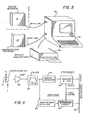
line 2B-2B of FIGURE 2A; - FIGURE 3 is a block diagram of a Holter replay/analysis unit which is used to receive data from recorders carried by the subject of FIGURE 1;
- FIGURE 4 is a block diagram of the manner in which vertical acceleration signals of the subject are processed;
- FIGURE 5 is a block diagram of a master digital clock which is included in the recorders forming a part of the system;
- FIGURE 6 is a block diagram showing the manner in which signals representing the speech of the subject and others are processed in the system;
- FIGURE 7 is a schematic representation of the incidence of speech by the subject and by others monitored by the system;
- FIGURE 8 is a series of curves representing the voice pattern of the subject of FIGURE 1 during normal conditions;
- FIGURE 9 is a series of curves showing the voice pattern of the subject of FIGURE 1 during emotional conditions;
- FIGURE 10 is a block diagram of a circuit which responds to the voice pattern of the subject to determine the emotional state of the subject;
- FIGURE 10A shows a series of curves useful in explaining the operation of the circuit of FIGURE 10; and
- FIGURE 11 is a block diagram of a circuit for detecting the incidence of speech from others apart from the subject and also for detecting ambient noise.
- In order for the Augmented Holter Monitoring (AHM) system of the invention to perform its desired monitoring functions, it is necessary for the
subject 18 of FIGURE 1 to carry certain sensors, transducers and other equipment as described in the Copending Application. For example, thesubject 18 may carry an existing miniature EKG Holterrecorder 16 in one of his shirt pockets. Usual EKG electrodes A-E are mounted on the subject and connected to the Holterrecorder 16 overleads 17. Thesubject 18 also carries aminiature accelerometer 20 on abelt 21, the accelerometer measuring vertical accelerations (Gz) of the subject at his centre of gravity. The accelerations (Gz) are converted to vertical forces (Fz) by the system in a manner fully described in U.S. Patent 4,830,021. - Two position sensor switches SW1 and SW2 are also attached to
subject 18, one at his waist and the other on his thigh. Switches SW1 and SW2 may be commercially available mercury gravity switches, or other appropriate gravity switches may be used. These switches serve to provide indications of the posture of the subject, specifically whether the subject is standing, sitting or lying down. The operation of such switches is described in some detail in US Patent 4,830,021. - A
multiple sensor 22 is mounted on the neck of thesubject 18. This multiple sensor may include two microphones, as will be described, as well as light and temperature sensors. The light sensor may be a simple photodiode circuit which generates electrical signals indicative of ambient light levels. The temperature sensor may be a thermistor circuit which generates electrical signals indicative of ambient temperature. Thesensors 20, SW1, SW2 and 22 are all connected to a second recorder 27 which may fit into a second shirt pocket ofsubject 18, or which may be clipped to the Holterrecorder 16. Alternatively,recorder 24 may be combined in Holderrecorder 16. - As shown in FIGURES 2A and 2B,
multiple sensor 22 includes two microphones designated Mic "A" and Mic "B". Microphones Mic "A" and Mic "B" may be sub-miniature microphones of the dynamic, electrode or semiconductor type, and preferably have frequency responses in the range of 20-3000 Hz. Microphone Mic "B" is attached to the neck of subject 18 adjacent to the sterno- cleido-mastoid (SCM) muscle above the collar. Microphone Mic "B" registers strong vibrations from the voice of subject 18 (.3-3 KHz); weaker vibrations from external sources including voices (.3-3 KHz); and lower frequency vibrations due to muscle contractions of the subject occurring, for example, when the subject is asleep and is experiencing an emotional dream. Microphone Mic "B" should have a high/low frequency response at approximately 10 Hz to respond to the low frequency (16 Hz) of muscle activity. - Although the microphones Mic "A" and Mic "B" are shown displaced from one another in FIGURE 2A, microphone Mic "A", is preferably mounted on microphone Mic "B" as shown in FIGURE 21 B, and the microphones are acoustically isolated from one another. Microphone Mic "A" serves to register the speech of the subject as transmitted through air, and it also registers other sounds transmitted to it by air.
- A conventional Holder replay/
analysis unit 30 is shown in FIGURE 3. Therecorders unit 30 during replay, as shown, and data recorded onrecorders Unit 30 includes all usual components, including a computer, controls, displays, akeyboard 32 and aprinter 34, all of which are needed for processing, and displaying the augmented Holter data fromrecorders unit 30. - The vertical acceleration (Gz) outputs of
accelerometer 20 of FIGURE 1, which represents the locomotor activity of the subject, has a characteristic waveform which varies synchronously both in frequency and amplitude with the step frequency of the subject. The locomotor activity is such that a sample rate of one per minute, that is, the number of steps and mean force developed, is adequate. A circuit for achieving the foregoing would normally be incorporated intorecorder 24. Such a circuit is shown in the block diagram of FIGURE 4. - In FIGURE 4,
accelerometer 20 is connected to anamplifier 50 which, in turn, is connected through a bandpass filter 52 to aperiod detector 54. Theperiod detector 54 is connected to a counter 56 for detecting the frequency of the waveform. The output of counter 56 is connected to abus 58 which carries the signals from the counter to an appropriate multiplexer (MUPX). Filter 52 is also connected to a peak-to-peak detector 60 for detecting the amplitude of the wave form. The output of peak-to-peak detector 60 is connected to an averagingcircuit 62 whose output is also connected tobus 58. Counter 56 andintegrator circuit 62 are each reset by an appropriate one minute strobe, as shown. The multiplexer MUPX causes the date from the circuit of FIGURE 4 to be recorded inrecorder 24, multiplexed with other data from the sensors of FIGURE 1. All of the data is preferably recorded in digital form. - A
crystal time clock 100, as shown in FIGURES 5, is included inrecorder 24. The time clock may include the usual manual set controls 100A, 100B which are also shown in FIGURE 1. Discrete twenty-four hour time signals and a 1 min-1 code is generated by theclock 100. The discrete time signals are introduced tobus 58 which carries the signals to the multiplexer MUPX to be recorded in digital form inrecorder 24 multiplexed with the other digital data. A similar time clock may be included in recorder 16 (FIGURE 1) with manual time set controls 101A and 101B. Such a clock would provide all time signals in a single unit recorder. - The outputs from microphones Mic "A" and Mic "B" of FIGURES 2A and 2B are amplified by
respective log amplifiers recorder 24. The amplified outputs from the log amplifiers are compared in alevel comparator 154 for amplitude differences. Thecomparator 154 provides output signals which distinguish the subject's speech from the speech of others, and such signals are applied tobus 58 to be carried to multiplexer MUPX and to be recorded inrecorder 24 in digital form. The circuit of FIGURE 6 also includes atimer 156 which provides time signals for timing the duration of speech components of the subject and of others. The speech of the subject and the speech of others may be distinguished because of amplitude differences, as shown in the representation of FIGURE 7. - The normal voice of the subject 18, when not under emotional stress, is represented by curves A, B and C in FIGURE 8; and the voice of the subject when under emotional stress is represented by the curves of FIGURE 9. The speech of the subject and its emotional content is detected by the duty cycle of the sound envelopes, and this is achieved by comparing the ratios of the on and off times of the speech of the subject. That is, as the subject becomes emotional there will be less space between the words and the words will be shorter. It is also desirable to include an amplitude detector, since a raised voice is also a usual concomitant of emotion.
- A circuit for detecting tie emotional content of the speech of the subject is included in
recorder 24, and a typical circuit is shown in block diagram in FIGURE 10. In FIGURE 10, the microphone Mic "B" is connected to alog amplifiers 250 which, in turn, is connected through a bandpass filter 52 to a precisionactive rectifier 254. The output ofrectifier 254 is passed through a filter andDC clamp circuit 256 to athreshold detector 258. The threshold detector is connected to the "on" input of atimer 260 which measures the on and off time of the speech. - The off time must be limited after an "on" cycle, otherwise it will count long periods, for example, between sentences.
- Such limitation is achieved by a fixed
length delay circuit 262 and a "not" gate 264. The output of the "not" gate is connected to the "off" input oftime 260. The output ofthreshold detector 258 is also applied to a differentiating circuit C1, R1, which is connected to delaycircuit 262 through a diode D1. - Curves A, B and C of FIGURE 10A represent the waveform of the various signals in the circuit of FIGURE 10. Curve A is the on/off signal, which is differentiated by the differentiator C1, R1 to generate a negative-going trigger (curve B) each time signal A goes negative. Trigger signal B triggers
delay circuit 262 at time intervals longer than the usual delay between words.Delay circuit 262 is reset by each negative trigger B, and when it is not reset, its output C is high. -
Timer 260 is turned on whenever signal A is low, and it is turned off whenever signal A is low. Should signal A remain low after a predetermined time interval established bydelay circuit 262, it is turned off by trigger C going high while signal A is low by virtue of "not" gate 264. - As shown, the normal voice and emotional voice of the subject appears at the output of
filter 252, as represented by the curve A in each of the diagrams of FIGURES 8 and 9. The rectified waveforms B of FIGURES 8 and 9 appear at the output of the filter andclamp circuit 256 in FIGURE 10, and that output is transformed into a series of pulses bythreshold detector 258, the pulses being shown by curves C in FIGURES 8 and 9. The closer the pulses in the curves C are together, and the shorter the pulses, the more emotional is the speech of the subject 18. Pulses from thethreshold detector 258 are applied to thetimers bus 58 to be recorded inrecorder 24. - The circuit of FIGURE 10 also includes a peak detector 257 and an
averaging circuit 258, which serve as an amplitude detector, for the reasons stated above. - As mentioned above, the speech of others and external noise is detected by microphone Mic "A" and is processed by the circuit of FIGURE 11. Microphone Mic "A" is connected to a
log amplifier 350 which, in turn, is connected through abandpass filter 352 to anactive rectifier 354. The output of the active rectifier is passed through afilter 356 whose output, in turn, is passed to adetector 358. Output ofdetector 358 is connected to atime 360 whose output, in turn, is fed to the multiplexer MUPX overbus 58. - The circuit of FIGURE 11 provides an output representative of the presence of the speech of others, and the emotional content of the speech. Noise is determined by the presence of a continuous background which results in an output from microphone Mic "A" which is of greater amplitude than the output of microphone Mic "B".
- As mentioned above, the
multiple sensor 22 of FIGURE 1 which is mounted on the neck of subject 18 also contains a simple photodiode which is encoded into several light levels so that signals representing ambient light levels may be applied tobus 58 and transmitted to multiplexer MUPX. As also mentioned, temperature readings are provided by including a thermistor insensor 22 and by applying its output tobus 58. The posture of the subject is also detected by applying signals from the posture sensors SW1 and SW2 of FIGURE 1 andbus 58, and utilizing the signals in the manner described in U.S. Patent 4,830,021. - In the foregoing manner, all of the augmented data from
sensors 20, SW1, SW2 and 22 in FIGURE 1 is multiplexed and recorded in digital form onrecorder 24. Accordingly, the data collected by the system described above includes physical activity which requires increased heart work. The largest load in the usual subject is walking-jogging- running (locomotor activity). The monitoring of such activity is described in U.S. Patent 4,830,021 which discloses a system by which such activity may be accurately detected and recorded. - In addition to physical activity, the monitoring system of the invention serves to detect and record emotional events. These emotional events are detected and recorded in the system of the invention directly, rather than relying on questionable and variable data such as galvanic skin response, as is sometimes used in the prior art. Two events known to be frequently associated with emotional stress are recorded, as described, and these comprise the presence of subject's speech and conversation, as well as dream states. The voice patterns are analyzed for emotional indicators.
- Other conditions known either to effect cardiac activity or which may define cardiac activities are also recorded, and these include subject posture, that is lying, sitting, standing; as well as ambient conditions such as air temperature and ambient light level.
- The invention provides, therefore, an improved cardiovascular monitoring system which detects the emotional state of a subject, and which generates signals indicative of the emotional states together with signals indicative of certain physical activities of the subject. The monitoring system records these signals, together with the EKG signals of the subject to enable an examination to be made of the physical activities and emotional states of the subject which could cause detected abnormalities in the EKG signals.
- It will be appreciated that while a particular embodiment of the invention has been shown and described, modifications may be made. It is intended in the claims to cover all modifications which come within the true spirit and scope of the invention.
Claims (11)
Applications Claiming Priority (2)
| Application Number | Priority Date | Filing Date | Title |
|---|---|---|---|
| US554421 | 1983-11-22 | ||
| US07/554,421 US5036856A (en) | 1990-07-19 | 1990-07-19 | Cardiovascular monitoring system |
Publications (2)
| Publication Number | Publication Date |
|---|---|
| EP0467502A2 true EP0467502A2 (en) | 1992-01-22 |
| EP0467502A3 EP0467502A3 (en) | 1992-03-18 |
Family
ID=24213264
Family Applications (1)
| Application Number | Title | Priority Date | Filing Date |
|---|---|---|---|
| EP19910303239 Ceased EP0467502A3 (en) | 1990-07-19 | 1991-04-11 | Improved cardiovascular monitoring system |
Country Status (2)
| Country | Link |
|---|---|
| US (1) | US5036856A (en) |
| EP (1) | EP0467502A3 (en) |
Families Citing this family (36)
| Publication number | Priority date | Publication date | Assignee | Title |
|---|---|---|---|---|
| US5125412A (en) * | 1990-07-23 | 1992-06-30 | Thornton William E | Musculoskeletal activity monitor |
| US5197489A (en) * | 1991-06-17 | 1993-03-30 | Precision Control Design, Inc. | Activity monitoring apparatus with configurable filters |
| US5238001A (en) * | 1991-11-12 | 1993-08-24 | Stuart Medical Inc. | Ambulatory patient monitoring system having multiple monitoring units and optical communications therebetween |
| US5353793A (en) * | 1991-11-25 | 1994-10-11 | Oishi-Kogyo Company | Sensor apparatus |
| DE69328011T2 (en) * | 1992-12-11 | 2000-08-03 | Siemens Medical Systems Inc | Portable modular patient monitor with data acquisition module |
| US5566676A (en) * | 1992-12-11 | 1996-10-22 | Siemens Medical Systems, Inc. | Pressure data acquisition device for a patient monitoring system |
| US5375604A (en) * | 1992-12-11 | 1994-12-27 | Siemens Medical Electronics, Inc. | Transportable modular patient monitor |
| CA2121413A1 (en) * | 1993-04-22 | 1994-10-23 | Gregory A. Mckeag | Method and system for context extraction of a realtime database |
| US5381798A (en) * | 1993-11-02 | 1995-01-17 | Quinton Instrument Company | Spread spectrum telemetry of physiological signals |
| US6049730A (en) * | 1998-12-28 | 2000-04-11 | Flaga Hf | Method and apparatus for improving the accuracy of interpretation of ECG-signals |
| DE102005059435A1 (en) * | 2005-12-13 | 2007-06-14 | Robert Bosch Gmbh | Device for noninvasive blood pressure measurement |
| US8838217B2 (en) | 2009-11-10 | 2014-09-16 | Makor Issues And Rights Ltd. | System and apparatus for providing diagnosis and personalized abnormalities alerts and for providing adaptive responses in clinical trials |
| US10216893B2 (en) | 2010-09-30 | 2019-02-26 | Fitbit, Inc. | Multimode sensor devices |
| US9167991B2 (en) | 2010-09-30 | 2015-10-27 | Fitbit, Inc. | Portable monitoring devices and methods of operating same |
| US9126055B2 (en) | 2012-04-20 | 2015-09-08 | Cardiac Science Corporation | AED faster time to shock method and device |
| US11029199B2 (en) | 2012-06-22 | 2021-06-08 | Fitbit, Inc. | Ambient light determination using physiological metric sensor data |
| US9044149B2 (en) | 2012-06-22 | 2015-06-02 | Fitbit, Inc. | Heart rate data collection |
| US8954135B2 (en) | 2012-06-22 | 2015-02-10 | Fitbit, Inc. | Portable biometric monitoring devices and methods of operating same |
| US9044171B2 (en) | 2012-06-22 | 2015-06-02 | Fitbit, Inc. | GPS power conservation using environmental data |
| US9005129B2 (en) | 2012-06-22 | 2015-04-14 | Fitbit, Inc. | Wearable heart rate monitor |
| US9049998B2 (en) | 2012-06-22 | 2015-06-09 | Fitbit, Inc. | Biometric monitoring device with heart rate measurement activated by a single user-gesture |
| US9597014B2 (en) | 2012-06-22 | 2017-03-21 | Fitbit, Inc. | GPS accuracy refinement using external sensors |
| US9042971B2 (en) | 2012-06-22 | 2015-05-26 | Fitbit, Inc. | Biometric monitoring device with heart rate measurement activated by a single user-gesture |
| US8948832B2 (en) | 2012-06-22 | 2015-02-03 | Fitbit, Inc. | Wearable heart rate monitor |
| JP6031863B2 (en) * | 2012-07-19 | 2016-11-24 | 株式会社Jvcケンウッド | Heart sound analysis apparatus, heart sound analysis method, and heart sound analysis program |
| US9039614B2 (en) | 2013-01-15 | 2015-05-26 | Fitbit, Inc. | Methods, systems and devices for measuring fingertip heart rate |
| US8976062B2 (en) | 2013-04-01 | 2015-03-10 | Fitbit, Inc. | Portable biometric monitoring devices having location sensors |
| US10512407B2 (en) | 2013-06-24 | 2019-12-24 | Fitbit, Inc. | Heart rate data collection |
| US9392946B1 (en) | 2015-05-28 | 2016-07-19 | Fitbit, Inc. | Heart rate sensor with high-aspect-ratio photodetector element |
| US11206989B2 (en) | 2015-12-10 | 2021-12-28 | Fitbit, Inc. | Light field management in an optical biological parameter sensor |
| US10568525B1 (en) | 2015-12-14 | 2020-02-25 | Fitbit, Inc. | Multi-wavelength pulse oximetry |
| US10433739B2 (en) | 2016-04-29 | 2019-10-08 | Fitbit, Inc. | Multi-channel photoplethysmography sensor |
| US10918907B2 (en) | 2016-08-14 | 2021-02-16 | Fitbit, Inc. | Automatic detection and quantification of swimming |
| US11051706B1 (en) | 2017-04-07 | 2021-07-06 | Fitbit, Inc. | Multiple source-detector pair photoplethysmography (PPG) sensor |
| US10388034B2 (en) * | 2017-04-24 | 2019-08-20 | International Business Machines Corporation | Augmenting web content to improve user experience |
| US11726105B2 (en) * | 2019-06-26 | 2023-08-15 | Qualcomm Incorporated | Piezoelectric accelerometer with wake function |
Citations (5)
| Publication number | Priority date | Publication date | Assignee | Title |
|---|---|---|---|---|
| US4100536A (en) * | 1976-10-07 | 1978-07-11 | Thomas S. Ball | Bio-alarm security system |
| FR2501996A1 (en) * | 1981-03-19 | 1982-09-24 | Silicone Medicale | Penis plethysmograph to detect nocturnal erection phase - contains also detector of REM sleep phase and records coincidence of both events to distinguish cause of impotence |
| US4803996A (en) * | 1987-09-28 | 1989-02-14 | Nippon Colin Co., Ltd. | Cardiovascular monitor |
| US4830021A (en) * | 1988-08-29 | 1989-05-16 | Thornton William E | Monitoring system for locomotor activity |
| US4905706A (en) * | 1988-04-20 | 1990-03-06 | Nippon Colin Co., Ltd. | Method an apparatus for detection of heart disease |
Family Cites Families (6)
| Publication number | Priority date | Publication date | Assignee | Title |
|---|---|---|---|---|
| US3548806A (en) * | 1968-06-26 | 1970-12-22 | Gen Electric | Mass emotional reaction measurement system |
| US3675640A (en) * | 1970-04-09 | 1972-07-11 | Gatts J D | Method and apparatus for dynamic health testing evaluation and treatment |
| US3894533A (en) * | 1973-11-02 | 1975-07-15 | American Optical Corp | Vital sign trend intuitive display system |
| US4483346A (en) * | 1983-08-25 | 1984-11-20 | Intech Systems Corp. | Electrocardiograph with digitally-printing waveform display |
| US4827943A (en) * | 1986-09-23 | 1989-05-09 | Advanced Medical Technologies, Inc. | Portable, multi-channel, physiological data monitoring system |
| US4883063A (en) * | 1987-05-29 | 1989-11-28 | Electric Power Research Institute, Inc. | Personal monitor and process for heat and work stress |
-
1990
- 1990-07-19 US US07/554,421 patent/US5036856A/en not_active Expired - Lifetime
-
1991
- 1991-04-11 EP EP19910303239 patent/EP0467502A3/en not_active Ceased
Patent Citations (5)
| Publication number | Priority date | Publication date | Assignee | Title |
|---|---|---|---|---|
| US4100536A (en) * | 1976-10-07 | 1978-07-11 | Thomas S. Ball | Bio-alarm security system |
| FR2501996A1 (en) * | 1981-03-19 | 1982-09-24 | Silicone Medicale | Penis plethysmograph to detect nocturnal erection phase - contains also detector of REM sleep phase and records coincidence of both events to distinguish cause of impotence |
| US4803996A (en) * | 1987-09-28 | 1989-02-14 | Nippon Colin Co., Ltd. | Cardiovascular monitor |
| US4905706A (en) * | 1988-04-20 | 1990-03-06 | Nippon Colin Co., Ltd. | Method an apparatus for detection of heart disease |
| US4830021A (en) * | 1988-08-29 | 1989-05-16 | Thornton William E | Monitoring system for locomotor activity |
Non-Patent Citations (1)
| Title |
|---|
| PROC. OF THE EIGHTH ANN. CONF. OF THE IEEE/ENGINEERING IN MEDICINE AND BIOLOGY SOCIETY vol. 1, 10 November 1986, FORT WORTH/TX, US pages 579 - 583; R.M. GLASER ET AL.: 'A System for Monitoring Daily Ambulatory Activity' * |
Also Published As
| Publication number | Publication date |
|---|---|
| US5036856A (en) | 1991-08-06 |
| EP0467502A3 (en) | 1992-03-18 |
Similar Documents
| Publication | Publication Date | Title |
|---|---|---|
| US5036856A (en) | Cardiovascular monitoring system | |
| US4993421A (en) | Cardiac monitoring system | |
| US5349962A (en) | Method and apparatus for detecting epileptic seizures | |
| US7137955B2 (en) | Methods and systems for distal recording of phonocardiographic signals | |
| US5280791A (en) | Monitor system for determining the sleep stages of a person | |
| US5080105A (en) | Cardiovascular monitoring system | |
| EP0444594B1 (en) | Method and apparatus for detecting and analyzing the swallowing activity in a subject | |
| US5682898A (en) | Respiration rate measuring apparatus | |
| CA2624718C (en) | Method and system for high-resolution extraction of quasi-periodic signals | |
| JPH10510440A (en) | Pulse oximeter for heart rate synchronization using virtual trigger | |
| JPH05505954A (en) | Myocardial ischemia detection system | |
| US4941477A (en) | Method and apparatus for detection of deception | |
| WO2006050725A1 (en) | Method and apparatus for recording and presentation of physiological data | |
| Tuomisto et al. | The ambulatory measurement of posture, thigh acceleration, and muscle tension and their relationship to heart rate | |
| JPH07376A (en) | Cough recording system | |
| JPH04161143A (en) | Physical exercise recorder | |
| JPH07204169A (en) | Device for detecting information on living body and its applied apparatus | |
| DE69634901D1 (en) | DEVICE FOR MEASURING INDUCED INTERFERENCE TUNES FOR DETERMINING THE PHYSIOLOGICAL CONDITION OF THE HUMAN ARTERY SYSTEM | |
| EP0984723B1 (en) | Cardiovascular monitor | |
| EP0468611A2 (en) | Musculoskeletal activity monitoring system | |
| Harshfield et al. | A validation study of the Del Mar Avionics Pressurometer IV according to AAMI guidelines | |
| Ng et al. | Accelerometer-based body-position sensing for ambulatory electrocardiographic monitoring | |
| JP2003225211A (en) | Detecting system for simultaneously measuring electrocardiogram, pulse, and voice, and analyzing system including the same | |
| JPH05329110A (en) | Active state bioinformation measuring/recording apparatus | |
| Fixler et al. | Ambulatory blood pressure monitoring in hypertensive adolescents |
Legal Events
| Date | Code | Title | Description |
|---|---|---|---|
| PUAI | Public reference made under article 153(3) epc to a published international application that has entered the european phase |
Free format text: ORIGINAL CODE: 0009012 |
|
| AK | Designated contracting states |
Kind code of ref document: A2 Designated state(s): DE FR GB IT |
|
| PUAL | Search report despatched |
Free format text: ORIGINAL CODE: 0009013 |
|
| AK | Designated contracting states |
Kind code of ref document: A3 Designated state(s): DE FR GB IT |
|
| 17P | Request for examination filed |
Effective date: 19920910 |
|
| 17Q | First examination report despatched |
Effective date: 19940314 |
|
| STAA | Information on the status of an ep patent application or granted ep patent |
Free format text: STATUS: THE APPLICATION HAS BEEN REFUSED |
|
| 18R | Application refused |
Effective date: 19950709 |