EP0466248A1 - Housing-half fastening arrangement - Google Patents
Housing-half fastening arrangement Download PDFInfo
- Publication number
- EP0466248A1 EP0466248A1 EP91201694A EP91201694A EP0466248A1 EP 0466248 A1 EP0466248 A1 EP 0466248A1 EP 91201694 A EP91201694 A EP 91201694A EP 91201694 A EP91201694 A EP 91201694A EP 0466248 A1 EP0466248 A1 EP 0466248A1
- Authority
- EP
- European Patent Office
- Prior art keywords
- housing
- housing halves
- fastening element
- fastening
- central portion
- Prior art date
- Legal status (The legal status is an assumption and is not a legal conclusion. Google has not performed a legal analysis and makes no representation as to the accuracy of the status listed.)
- Withdrawn
Links
Images
Classifications
-
- B—PERFORMING OPERATIONS; TRANSPORTING
- B26—HAND CUTTING TOOLS; CUTTING; SEVERING
- B26B—HAND-HELD CUTTING TOOLS NOT OTHERWISE PROVIDED FOR
- B26B19/00—Clippers or shavers operating with a plurality of cutting edges, e.g. hair clippers, dry shavers
- B26B19/38—Details of, or accessories for, hair clippers, or dry shavers, e.g. housings, casings, grips, guards
- B26B19/3853—Housing or handle
-
- B—PERFORMING OPERATIONS; TRANSPORTING
- B26—HAND CUTTING TOOLS; CUTTING; SEVERING
- B26B—HAND-HELD CUTTING TOOLS NOT OTHERWISE PROVIDED FOR
- B26B19/00—Clippers or shavers operating with a plurality of cutting edges, e.g. hair clippers, dry shavers
- B26B19/38—Details of, or accessories for, hair clippers, or dry shavers, e.g. housings, casings, grips, guards
-
- H—ELECTRICITY
- H05—ELECTRIC TECHNIQUES NOT OTHERWISE PROVIDED FOR
- H05K—PRINTED CIRCUITS; CASINGS OR CONSTRUCTIONAL DETAILS OF ELECTRIC APPARATUS; MANUFACTURE OF ASSEMBLAGES OF ELECTRICAL COMPONENTS
- H05K5/00—Casings, cabinets or drawers for electric apparatus
- H05K5/0004—Casings, cabinets or drawers for electric apparatus comprising several parts forming a closed casing
- H05K5/0013—Casings, cabinets or drawers for electric apparatus comprising several parts forming a closed casing assembled by resilient members
Definitions
- the invention relates to a housing-half quick-fastening arrangement, for example for a domestic appliance, comprising a fastening element of U-shaped cross-section with a central portion at the location of facing peripheral portions of the housing halves, the limbs of the U-shaped fastening element at least partly engaging around the housing halves.
- Such a housing-half fastening arrangement is known, for example from DE-A-31 19 018.
- the limbs of this known fastener comprise inwardly directed lugs engaging in corresponding grooves in the housing halves.
- the invention provides a housing-half fastening arrangement which affects the shape and construction of the housing halves to the least possible extent and is characterized in that the central portion of the fastening element comprises a retaining element of mushroom-shaped cross-section with a shank situated between the housing halves and with a head which engages behind the housing halves in the interior of the housing.
- the shaving apparatus shown in Figures 1 to 3 comprises a housing 1 with a shaving head 2 having two shaving units 3.
- the housing 1 comprises two housing halves 4 and 5 which are secured to one another by two identical fastening elements 6.
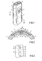
- a fastening element 6 is of U-shaped cross-section ( Figure 2) with a central portions 7 at the location of the facing peripheral portions 8 and 9 of the housing halves 4 and 5 respectively.
- the limbs 10 and 11 of the fastening element 6 partly engage around the housing halves 4 and 5 respectively, resulting in clamping forces K which hold the housing halves together.
- the central portion 7 of the fastening element 6 comprises a retaining element 12 of mushroom-shaped cross-section with a shank 13 situated between the peripheral portions 8 and 9 and with a head 14 engaging behind the housing halves in the interior of the housing. The fastening element 6 is thus secured to the housing 1.
- the fastening element 6 can be mounted simply and quickly by placing the housing halves onto each other and subsequently pressing the retaining element 12 into the seam 15 between the peripheral portions 8 and 9 until the head 14 snaps behind the housing halves 4 and 5. This results in a slight elastic deformation of the limbs 10 and 11, causing them to engage tightly with the housing halves. Tools and separate fixing means such as bolts are not needed. Moreover, it is not necessary to form the housing halves with grooves for the fastening element. In order to obtain a smooth housing surface the housing halves 4 and 5 may be provided with re-entrant portions 16 adjoining the seam 15 to take up the limbs 10 and 11.
- the fastening element 6 is preferably constructed as an integral plastics part.
- the head 14 may be provided with bevels 17 and 18 and the peripheral portions 8 and 9 may be provided with bevels 19 and 20 respectively.
- the retaining element 12 may extend over the entire length of the fastening element 6 to provide a correct sealing of the seam 15.
- the fastening element 6 may be provided with a plurality of spaced-apart retaining elements.
- the housing halves may then be constructed as shown in Figure 3, in which for the sake of clarity the fastening element itself is not shown.
- the housing halves 4 and 5 comprise facing projections 21 and 22 respectively which interengage in such a way that openings 23 are left for the shanks 13 of the retaining elements 12. This also ensures that the fastening elements 6 are locked in the longitudinal direction.
Landscapes
- Engineering & Computer Science (AREA)
- Life Sciences & Earth Sciences (AREA)
- Forests & Forestry (AREA)
- Mechanical Engineering (AREA)
- Microelectronics & Electronic Packaging (AREA)
- Dry Shavers And Clippers (AREA)
- Connector Housings Or Holding Contact Members (AREA)
Abstract
A housing-half quick-fastening arrangement, for example for a domestic appliance, comprises a fastening element (6) of U-shaped cross-section with a central portion (7) at the location of facing peripheral portions (8,9) of the housing halves (4,5), the limbs (10, 11) of the U-shaped fastening element at least partly engaging around the housing halves. The central portion (7) of the fastening element comprises a retaining element (12) of mushroom-shaped cross-section with a shank (13) situated between the housing halves and with a head (14) which engages behind the housing halves in the interior of the housing.
Description
- The invention relates to a housing-half quick-fastening arrangement, for example for a domestic appliance, comprising a fastening element of U-shaped cross-section with a central portion at the location of facing peripheral portions of the housing halves, the limbs of the U-shaped fastening element at least partly engaging around the housing halves.
- Such a housing-half fastening arrangement is known, for example from DE-A-31 19 018. The limbs of this known fastener comprise inwardly directed lugs engaging in corresponding grooves in the housing halves.
- The invention provides a housing-half fastening arrangement which affects the shape and construction of the housing halves to the least possible extent and is characterized in that the central portion of the fastening element comprises a retaining element of mushroom-shaped cross-section with a shank situated between the housing halves and with a head which engages behind the housing halves in the interior of the housing.
- Special embodiments have been defined in the subsidiary Claims.
- The invention will now be described in more detail with reference to the Figures, which show an exemplary embodiment.
- Figure 1 is a perspective view of a shaving apparatus employing the housing-half fastening arrangement in accordance with the invention.
- Figure 2 is a cross-sectional view of a part, taken on the line II-II in Figure 1.
- Figure 3 is a detail of a view of the housing at the location of the facing peripheral portions of the housing halves.
- The shaving apparatus shown in Figures 1 to 3 comprises a housing 1 with a shaving head 2 having two shaving units 3.
- The housing 1 comprises two
housing halves identical fastening elements 6. - A
fastening element 6 is of U-shaped cross-section (Figure 2) with acentral portions 7 at the location of the facingperipheral portions housing halves - The
limbs fastening element 6 partly engage around thehousing halves - The
central portion 7 of thefastening element 6 comprises aretaining element 12 of mushroom-shaped cross-section with ashank 13 situated between theperipheral portions head 14 engaging behind the housing halves in the interior of the housing. Thefastening element 6 is thus secured to the housing 1. - The fastening
element 6 can be mounted simply and quickly by placing the housing halves onto each other and subsequently pressing theretaining element 12 into theseam 15 between theperipheral portions head 14 snaps behind thehousing halves limbs housing halves re-entrant portions 16 adjoining theseam 15 to take up thelimbs - The
fastening element 6 is preferably constructed as an integral plastics part. To facilitate mounting thehead 14 may be provided withbevels peripheral portions bevels - The
retaining element 12 may extend over the entire length of thefastening element 6 to provide a correct sealing of theseam 15. - However, alternatively, the
fastening element 6 may be provided with a plurality of spaced-apart retaining elements. The housing halves may then be constructed as shown in Figure 3, in which for the sake of clarity the fastening element itself is not shown. Thehousing halves projections openings 23 are left for theshanks 13 of theretaining elements 12. This also ensures that thefastening elements 6 are locked in the longitudinal direction. - By means of the fastening elements described above it is possible to achieve an effective sealing of the seam between the housing halves, thereby enabling the electrical safety requirements imposed on the apparatus to be met in a simple way.
Claims (4)
1. A housing-half quick-fastening arrangement, for example for a domestic appliance, comprising a fastening element of U-shaped cross-section with a central portion at the location of facing peripheral portions of the housing halves, the limbs of the U-shaped fastening element at least partly engaging around the housing halves, characterized in that the central portion of the fastening element comprises a retaining element of mushroom-shaped cross-section with a shank situated between the housing halves and with a head which engages behind the housing halves in the interior of the housing.
2. A housing-half quick-fastening arrangement as claimed in Claim 1, comprising an elongate fastening element which extends along a seam of the housing, characterized in that the central portion comprises a single retaining element which extends in the longitudinal direction.
3. A housing-half quick-fastening arrangement as claimed in Claim 1, comprising an elongate fastening element which extends along a seam of the housing, characterized in that the central portion comprises a plurality of spaced-apart retaining elements.
4. A housing-half quick-fastening arrangement as claimed in Claim 3, characterized in that the housing halves comprise interengaging portions which leave openings for the retaining elements.
Applications Claiming Priority (2)
| Application Number | Priority Date | Filing Date | Title |
|---|---|---|---|
| NL9001559 | 1990-07-09 | ||
| NL9001559A NL9001559A (en) | 1990-07-09 | 1990-07-09 | HOUSE HALF ATTACHMENT. |
Publications (1)
| Publication Number | Publication Date |
|---|---|
| EP0466248A1 true EP0466248A1 (en) | 1992-01-15 |
Family
ID=19857385
Family Applications (1)
| Application Number | Title | Priority Date | Filing Date |
|---|---|---|---|
| EP91201694A Withdrawn EP0466248A1 (en) | 1990-07-09 | 1991-07-02 | Housing-half fastening arrangement |
Country Status (3)
| Country | Link |
|---|---|
| EP (1) | EP0466248A1 (en) |
| JP (1) | JPH0489261U (en) |
| NL (1) | NL9001559A (en) |
Cited By (2)
| Publication number | Priority date | Publication date | Assignee | Title |
|---|---|---|---|---|
| WO2002054725A1 (en) * | 2000-12-29 | 2002-07-11 | Vertu Ltd | Casing for a portable electronic device |
| US7234421B2 (en) | 2001-03-22 | 2007-06-26 | Nokia Corporation | Animal data gathering method and device |
Citations (2)
| Publication number | Priority date | Publication date | Assignee | Title |
|---|---|---|---|---|
| DE3119018A1 (en) * | 1980-05-15 | 1982-05-13 | Matsushita Electric Works Ltd., Kadoma, Osaka | ELECTRIC SHAVER |
| DE3742557A1 (en) * | 1987-12-16 | 1989-06-29 | Sueddeutsche Kuehler Behr | Connecting profile for connecting the borders of two housing parts |
-
1990
- 1990-07-09 NL NL9001559A patent/NL9001559A/en not_active Application Discontinuation
-
1991
- 1991-07-02 EP EP91201694A patent/EP0466248A1/en not_active Withdrawn
- 1991-07-04 JP JP5968091U patent/JPH0489261U/ja active Pending
Patent Citations (2)
| Publication number | Priority date | Publication date | Assignee | Title |
|---|---|---|---|---|
| DE3119018A1 (en) * | 1980-05-15 | 1982-05-13 | Matsushita Electric Works Ltd., Kadoma, Osaka | ELECTRIC SHAVER |
| DE3742557A1 (en) * | 1987-12-16 | 1989-06-29 | Sueddeutsche Kuehler Behr | Connecting profile for connecting the borders of two housing parts |
Cited By (2)
| Publication number | Priority date | Publication date | Assignee | Title |
|---|---|---|---|---|
| WO2002054725A1 (en) * | 2000-12-29 | 2002-07-11 | Vertu Ltd | Casing for a portable electronic device |
| US7234421B2 (en) | 2001-03-22 | 2007-06-26 | Nokia Corporation | Animal data gathering method and device |
Also Published As
| Publication number | Publication date |
|---|---|
| NL9001559A (en) | 1992-02-03 |
| JPH0489261U (en) | 1992-08-04 |
Similar Documents
| Publication | Publication Date | Title |
|---|---|---|
| US4990722A (en) | Ducting for electrical conductors and the like with stiffening arrangement and corresponding clamp | |
| EP0408212B1 (en) | Electrical connector stiffener device | |
| US10665981B2 (en) | Modular holding frame for plug connectors | |
| KR900017235A (en) | Connector assembly with coding element | |
| DE3380158D1 (en) | Electrical connector provided with a locking member | |
| EP0663705A3 (en) | Filtered electrical connector assembly. | |
| ES2106675A1 (en) | Method of manufacturing a grounding connector and improved grounding connector | |
| JPH07110599B2 (en) | Gas bag restraint system assembly | |
| DE69423827T2 (en) | Electrical connector with locking system for connection elements | |
| FR2738406B1 (en) | ELECTRICAL OUTLET WITH A CALIPER | |
| GB2287141B (en) | An electrical connector assembly | |
| EP0538489B1 (en) | Construction for fixing side covers to bearing for rectilinear motion | |
| EP0722204A3 (en) | Electrical connector having a mating slide with customized camming slot | |
| EP0466248A1 (en) | Housing-half fastening arrangement | |
| CA2085252A1 (en) | Harness and cable branch-off | |
| GB2149234A (en) | Flexible backshell of electrical connector | |
| RU2739842C1 (en) | Holding frame for industrial plug connector | |
| GB1602864A (en) | Electrical ducting | |
| EP0059566A1 (en) | Two way cover assembly | |
| GB9407015D0 (en) | Electrical connector housing assembly with improved locking means | |
| SU996754A1 (en) | Clamping device for angular connection of parts mainly for furniture parts | |
| EP0442459B1 (en) | Multi-purpose bracket | |
| FR2691846B1 (en) | ELECTRIC SOCKET WITH SELF-INSULATING CONTACT. | |
| EP0797221A3 (en) | PTC element and its mounting member assembly for electrical junction box | |
| EP1223650B1 (en) | Pressure plug for supporting electric cables |
Legal Events
| Date | Code | Title | Description |
|---|---|---|---|
| PUAI | Public reference made under article 153(3) epc to a published international application that has entered the european phase |
Free format text: ORIGINAL CODE: 0009012 |
|
| AK | Designated contracting states |
Kind code of ref document: A1 Designated state(s): DE FR GB NL |
|
| 17P | Request for examination filed |
Effective date: 19920714 |
|
| 17Q | First examination report despatched |
Effective date: 19930301 |
|
| STAA | Information on the status of an ep patent application or granted ep patent |
Free format text: STATUS: THE APPLICATION IS DEEMED TO BE WITHDRAWN |
|
| 18D | Application deemed to be withdrawn |
Effective date: 19931011 |