EP0463728A2 - Increasing storage density of information storage media - Google Patents
Increasing storage density of information storage media Download PDFInfo
- Publication number
- EP0463728A2 EP0463728A2 EP91304415A EP91304415A EP0463728A2 EP 0463728 A2 EP0463728 A2 EP 0463728A2 EP 91304415 A EP91304415 A EP 91304415A EP 91304415 A EP91304415 A EP 91304415A EP 0463728 A2 EP0463728 A2 EP 0463728A2
- Authority
- EP
- European Patent Office
- Prior art keywords
- light
- light beam
- image
- storage medium
- accordance
- Prior art date
- Legal status (The legal status is an assumption and is not a legal conclusion. Google has not performed a legal analysis and makes no representation as to the accuracy of the status listed.)
- Granted
Links
Images


Classifications
-
- G—PHYSICS
- G11—INFORMATION STORAGE
- G11B—INFORMATION STORAGE BASED ON RELATIVE MOVEMENT BETWEEN RECORD CARRIER AND TRANSDUCER
- G11B7/00—Recording or reproducing by optical means, e.g. recording using a thermal beam of optical radiation by modifying optical properties or the physical structure, reproducing using an optical beam at lower power by sensing optical properties; Record carriers therefor
- G11B7/12—Heads, e.g. forming of the optical beam spot or modulation of the optical beam
- G11B7/13—Optical detectors therefor
- G11B7/131—Arrangement of detectors in a multiple array
-
- G—PHYSICS
- G11—INFORMATION STORAGE
- G11B—INFORMATION STORAGE BASED ON RELATIVE MOVEMENT BETWEEN RECORD CARRIER AND TRANSDUCER
- G11B11/00—Recording on or reproducing from the same record carrier wherein for these two operations the methods are covered by different main groups of groups G11B3/00 - G11B7/00 or by different subgroups of group G11B9/00; Record carriers therefor
- G11B11/10—Recording on or reproducing from the same record carrier wherein for these two operations the methods are covered by different main groups of groups G11B3/00 - G11B7/00 or by different subgroups of group G11B9/00; Record carriers therefor using recording by magnetic means or other means for magnetisation or demagnetisation of a record carrier, e.g. light induced spin magnetisation; Demagnetisation by thermal or stress means in the presence or not of an orienting magnetic field
- G11B11/105—Recording on or reproducing from the same record carrier wherein for these two operations the methods are covered by different main groups of groups G11B3/00 - G11B7/00 or by different subgroups of group G11B9/00; Record carriers therefor using recording by magnetic means or other means for magnetisation or demagnetisation of a record carrier, e.g. light induced spin magnetisation; Demagnetisation by thermal or stress means in the presence or not of an orienting magnetic field using a beam of light or a magnetic field for recording by change of magnetisation and a beam of light for reproducing, i.e. magneto-optical, e.g. light-induced thermomagnetic recording, spin magnetisation recording, Kerr or Faraday effect reproducing
- G11B11/10532—Heads
- G11B11/10541—Heads for reproducing
- G11B11/10543—Heads for reproducing using optical beam of radiation
-
- G—PHYSICS
- G11—INFORMATION STORAGE
- G11B—INFORMATION STORAGE BASED ON RELATIVE MOVEMENT BETWEEN RECORD CARRIER AND TRANSDUCER
- G11B7/00—Recording or reproducing by optical means, e.g. recording using a thermal beam of optical radiation by modifying optical properties or the physical structure, reproducing using an optical beam at lower power by sensing optical properties; Record carriers therefor
- G11B7/12—Heads, e.g. forming of the optical beam spot or modulation of the optical beam
- G11B7/135—Means for guiding the beam from the source to the record carrier or from the record carrier to the detector
- G11B7/1372—Lenses
-
- G—PHYSICS
- G11—INFORMATION STORAGE
- G11B—INFORMATION STORAGE BASED ON RELATIVE MOVEMENT BETWEEN RECORD CARRIER AND TRANSDUCER
- G11B7/00—Recording or reproducing by optical means, e.g. recording using a thermal beam of optical radiation by modifying optical properties or the physical structure, reproducing using an optical beam at lower power by sensing optical properties; Record carriers therefor
- G11B7/12—Heads, e.g. forming of the optical beam spot or modulation of the optical beam
- G11B7/135—Means for guiding the beam from the source to the record carrier or from the record carrier to the detector
- G11B7/1381—Non-lens elements for altering the properties of the beam, e.g. knife edges, slits, filters or stops
-
- G—PHYSICS
- G11—INFORMATION STORAGE
- G11B—INFORMATION STORAGE BASED ON RELATIVE MOVEMENT BETWEEN RECORD CARRIER AND TRANSDUCER
- G11B7/00—Recording or reproducing by optical means, e.g. recording using a thermal beam of optical radiation by modifying optical properties or the physical structure, reproducing using an optical beam at lower power by sensing optical properties; Record carriers therefor
- G11B7/12—Heads, e.g. forming of the optical beam spot or modulation of the optical beam
- G11B7/14—Heads, e.g. forming of the optical beam spot or modulation of the optical beam specially adapted to record on, or to reproduce from, more than one track simultaneously
Definitions
- This invention relates to increasing the storage density of optical drives, for example, magneto-optical, compact disk, and write-once-read-many (WORM) drives.
- optical drives for example, magneto-optical, compact disk, and write-once-read-many (WORM) drives.
- WORM write-once-read-many
- a laser produces a light beam that passes through an objective lens that focuses the light beam onto a magneto-optical disk.
- the central portion of the light beam heats a microscopic spot on a magnetic layer within the magneto-optical disk, while a biased magnetic field is applied in the vicinity of the light spot on the disk.
- the heat of the light spot temporarily lowers the coercivity of the magnetic layer.
- the coercivity of the magnetic layer is lowered enough that the magnetic field causes the magnetic orientation of the magnetic layer to reverse direction.
- the local orientation of the magnetic layer becomes fixed to form a domain on the disk representing a bit of information.
- the presence of a domain having a reversed magnetic orientation at a given location on the disk represents a "1" while the absence of such a domain represents a "0.”
- a laser In the reading process of typical magneto-optical drives, a laser produces a polarized light beam that passes through a first polarized beam splitter and passes through an objective lens that focuses the light beam onto a magneto-optical disk.
- the information stored at the point on the magneto-optical disk at which the light beam is focused causes the polarization of the light beam to shift slightly clockwise or slightly counterclockwise, depending on whether the information stored on the disk is a "1" or a "0,” as the light beam reflects off of the disk.
- the reflected light beam passes back through the objective lens along the same path as the path of the incident light beam.
- the objective lens collimates the reflected light beam, which returns to a light detector assembly.
- the number of concentric tracks (or the number of turns of a spiral track) can be increased, because the guard band can be located under an upper portion of the light spot as the drive reads one track (or turn of a spiral track), and under a lower portion of the light spot as the drive reads a neighboring track (or turn of a spiral track), without interference occurring between domains of information in neighboring tracks (or neighboring turns of the spiral track).
- the light beam is not affected by the domains of more than one track (or turn of a spiral track) at a time.
- the invention provides a new method of reading information in which, instead of analyzing the polarization of the entire reflected light beam, the reflected light beam is re-imaged to form a picture of the read spot.
- the re-imaged light spot contains more than one bit of information.
- the isolation of one or more details of the re-imaged spot is analogous to isolation of one or more details of a photograph.
- This invention is motivated by the realization that a domain can be written much smaller than a conventional reading process can resolve it.
- the invention enables densely written domains to be resolved, thereby increasing the range of useful recording densities for a given size of a read/write light spot.
- the invention features a light detection apparatus that includes at least one re-imaging lens that re-images a light beam reflected from an optical storage medium, to form an image of a light spot formed by the light beam on the storage medium. At least one detector detects a selected portion of the image. The selected portion of the image contains only such information as is encoded on a region of the optical data storage medium that is illuminated by a corresponding portion of the light spot.
- the re-imaging lens re-images the light beam onto a plate having a pinhole aperture.
- the re-imaging lens preferably has a focal length that is greater than a focal length of an objective lens that focuses the light beam on the storage medium and that collimates the light beam after reflection from the storage medium.
- the image on the plate is a magnified image of the light spot on the storage medium.
- the image on the plate is centered on the aperture.
- a central portion of the light beam that includes a central portion of the image passes through the aperture.
- the corresponding central portion of the light spot on the storage medium covers a location at which a domain of information is stored.
- a peripheral portion of the light beam that includes a peripheral portion of the image is blocked by the plate.
- the corresponding peripheral portion of the light spot covers locations on the storage medium at which domains of information other than the domain covered by the central portion of the light spot are stored.
- a collimating lens collimates the portion of the light beam that passes through the aperture.
- the storage medium is a magneto-optical disk.
- the magneto-optical disk contains domains that rotate an angle of polarization of the light beam as the light beam reflects off of the magneto-optical disk.
- a polarization beam splitter splits the portion of the light beam that passes through the aperture and the collimating lens into two parts having intensities proportional to the horizontal and vertical components of polarization of the reflected light beam.
- Two detectors respectively detect the two parts of the light beam.
- a polarization beam splitter splits the light beam reflected from the magneto-optical disk into two parts.
- Two re-imaging lenses re-image the two parts of the light beam in a manner such that the two parts of the light beam form images on a pair of respective combination detectors (detector arrays).
- Each combination detector includes an array of light-sensitive detection elements.
- the image on each combination detector includes a plurality of image portions covering a plurality of respective light-sensitive detection elements. Each image portion is an image of a portion of the light spot formed by the light beam on the storage medium.
- the polarization splitter splits the re-imaged light beam into the two parts, which are respectively detected by the two combination detectors.
- the invention provides detection systems that can resolve domains having dimensions smaller than the dimensions of the light spot on the disk by processing and conditioning the light beam after it is reflected from the storage media.
- the invention allows both the track density and the density of domains within each track to be increased without requiring structural changes to the information storage media or to the recording head. Only the detection apparatus need be modified.
- the invention reduces the cost per MBit of disk drives.
- the invention can be coupled with other schemes directed at increasing storage density, including the schemes outlined above in the Background section, to further increase storage density.
- the embodiments of the invention that utilize combination detectors improve the performance of magneto-optical drives by enabling multiple tracks of information on the disk to be read simultaneously.
- Fig. 1 is a graphical representation of the intensity of a light spot on a disk as a function of displacement.
- Fig. 2 is a schematic representation of a disk drive according to the invention.
- Fig. 3 is a schematic representation of one embodiment of a light detection apparatus according to the invention.
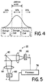
- Fig. 4 is a graphical representation of an example of the intensity of a re-imaged light spot versus displacement, according to the embodiment of the invention shown in Fig. 3.
- Fig. 5 is a schematic representation of another embodiment of a light detection apparatus according to the invention.
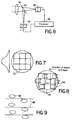
- Fig. 6 is a schematic representation of yet another embodiment of a light detection apparatus according to the invention.
- Fig. 7 is a graphical representation of the intensity and spatial distribution of a re-imaged light spot according to the embodiments of the invention shown in Figs. 5 and 6.
- Fig. 8 is a graphical representation of the spatial distribution of a re-imaged light spot according to the embodiments of the invention shown in Figs. 5 and 6, showing the locations at which domains are re-imaged.
- Fig. 9 is a schematic representation of servo pads that are encoded on a magneto-optical disk in order to enable tracking in the embodiments of the invention shown in Figs. 5 and 6.
- Fig. 10 is a flowchart diagram of the tracking procedure for the embodiments of the invention shown in Figs. 5 and 6.
- Fig. 11 is a schematic representation of a signal enhancement apparatus for use in conjunction with the embodiments of the invention shown in Figs. 5 and 6.
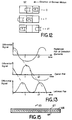
- Fig. 12 is a graphical representation of a re-imaged light spot according to the embodiments of the invention shown in Figs. 5 and 6, showing the relative positions of detector elements and images of domains at selected points in time.
- Fig. 13 is a graphical representation of differential signals corresponding to pairs of detector elements in the embodiments of the invention shown in Figs. 5 and 6.
- Fig. 14 is a schematic representation of a signal enhancement apparatus that reads multiple tracks of information simultaneously, for use in conjunction with the embodiments of the invention shown in Figs. 5 and 6.
- Fig. 15 is a schematic representation of a magneto-optical disk for use with a disk drive according to the invention.
- a light spot having a Gaussian distribution represented by curve 60 is formed on a magnetic layer of magneto-optical disk.
- the portion of the light spot that has an intensity greater than I threshold heats the underlying magnetic layer above a threshold at which the magnetic field causes the local orientation of the magnetic layer to reverse direction.
- a domain forms on the disk, having dimensions that match with the portion of the light spot having an intensity greater than I threshold .
- a laser 12 in a static optics package 14 produces a polarized light beam that passes through a polarized beam splitter 16.
- An objective lens 18 focuses the polarized light beam onto magneto-optical disk 20.
- the light beam reflects back through objective lens 18, which collimates the reflected light beam.
- the light beam returns to static optics package 14, within which polarized beam splitter 16 deflects the reflected light beam to light detection apparatus 22.
- light detection apparatus 22 includes a re-imaging lens 24 that re-images the reflected light beam onto a plate 26 having a pinhole aperture 28.
- Re-imaging lens 24 preferably has a focal length that is greater than the focal length of objective lens 18. Consequently, according to principles of microscope enlarging, the re-imaged light spot on plate 26 has a greater variance in its Gaussian distribution than the light spot on the magneto-optical disk. In other words, the light spot on plate 26 is a magnified image of the light spot that is formed on magneto-optical disk 20.
- a portion of the light beam corresponding to the central portion of the light spot on plate 26 passes through aperture 28.
- Collimating lens 30 collimates the portion of the light beam that passes through aperture 28.
- a polarized beam splitter 32 splits the collimated light beam into two parts each having an intensity proportional to a respective component of polarization of the reflected light beam.
- polarized beam splitter 32 might transmit the vertical component of polarization of the light and reflect the horizontal component of polarization of the light, in which case detectors 34 and 36 detect the intensity of the vertically polarized and horizontally polarized parts, respectively, of the light beam.
- Processor 38 subtracts the output of one of the detectors from the output of the other to obtain a differential signal representative of the angle of polarization of the reflected light beam.
- the differential signal indicates whether the location on magneto-optical disk 20 that is illuminated by the central portion of the light spot contains a "1" or a "0.”
- the light spot on plate 26 is a magnified image of the light spot on magneto-optical disk 20, which covers more than one domain.
- Fig. 4 shows a numerical example of the spatial distribution of the intensity of light incident on a spot that covers three domain cells on disk 20. Approximately twenty-five percent of the total light intensity of the light spot on disk 20 illuminates the leftmost domain cell, approximately twenty-five percent of the total light intensity illuminates the rightmost domain cell, and fifty percent of the total light intensity illuminates the central domain cell.
- the signal-to-noise ratio would be 0 dB, because the polarization of light reflected from the leftmost and rightmost domain cells would in effect cancel the polarization of light reflected from the central domain cell.
- the detection method of the invention only the central portion of the image of the light spot covers aperture 28.
- the portion of the light beam that corresponds to the portion of the light spot that illuminates the central domain cell on the disk reaches detectors 34 and 36.
- the dimensions of aperture 28 should match exactly the dimensions of a portion of the light spot that illuminates a domain of information on disk 20, so that the signal-to-noise ratio is maximized.
- the leftmost and rightmost domains do not interfere with the central portion of the re-imaged light beam that reaches detectors 34 and 36, and hence aperture 28 reduces cross-talk between the domains.
- the apparatus of Fig. 3 can resolve domains having dimensions smaller than the "read" light spot, at a cost of a slight reduction in the intensity of light reaching the detectors and hence a slight reduction in the signal-to-noise ratio.
- the signal-to-noise ratio is only 3 dB less than the signal-to-noise ratio associated with an ideal, infinitely large domain.
- light detection apparatus 22 includes a polarized beam splitter 40 that splits the reflected light beam into two parts each having an intensity proportional to a respective component of polarization of the reflected light beam.
- Re-imaging lenses 42 and 44 respectively re-image the two parts to the reflected light beam onto two combination detectors 46 and 48.
- Re-imaging lenses 42 and 44 each preferably have a focal length that is greater than the focal length of objective lens 18. Consequently, the re-imaged light spots on combination detectors 46 and 48 are magnified images of the light spot that is formed on magneto-optical disk 20.
- Combination detectors 46 and 48 each contain an array of light-sensitive detection elements that are illuminated by the re-imaged light spots.
- Processor 38 subtracts the outputs of light-sensitive detection elements in one array from the outputs of corresponding light-sensitive detection elements in the other array to obtain a set of differential signals representative of the angle of polarization of various portions of the reflected light beam.
- a single re-imaging lens 50 re-images the reflected light beam onto combination detectors 46 and 48 via polarized beam splitter 40, which splits the light beam into the two parts that are detected by combination detectors 46 and 48.
- the magnified re-imaged light spot on a combination detector 46 or 48 illuminates the array of light-sensitive detection elements 52 that are contained within the combination detector.
- the light spot has a Gaussian distribution of intensity on the combination detector as shown.
- Each light-sensitive detection element 52 in the array has a counterpart in the other array that is illuminated by the same portion of the re-imaged light spot.
- the magnified re-imaged light spot on a combination detector 46 or 48 can contain images 54 of several domains that are located on magneto-optical disk 20.
- domains of information are written onto magneto-optical disk 20 using a light beam that forms a light spot on the magneto-optical disk having approximately the same dimensions as the light spot that is used during the reading process.
- the cross-track size of the domains may be controlled by controlling the intensity of the light beam.
- the linear size of the domains along a track may be controlled by controlling the duration of pulses of a magnetic coil that causes dipoles in the magneto-optical disk to flip as the disk turns under the light beam.
- processor 38 subtracts the output of one of the detectors 34 or 36 from the output of the other detector to obtain a differential signal representative of the angle of polarization of the reflected light beam.
- the differential signal indicates whether the location on magneto-optical disk 20 that is illuminated by the central portion of the light spot contains a "1" or a "0.”
- tracking may be accomplished by means of a conventional sample servo tracking method or a pre-grooved disk tracking method.
- Figs. 9 and 10 illustrate an example of a sample servo tracking method that is used in conjunction with the embodiments of the invention shown in Figs. 5 and 6.
- Each track has a pair of servo pads 56 that are encoded in proximity to the center line 58 of the track, at the head of each sector of data on the magneto optical disk.
- one servo pad is encoded slightly above the center line and the other servo pad is encoded slightly below the center line of the track and displaced longitudinally along the track from the first servo pad.
- the servo pads may be domains similar to the domains of information encoded along the center line of the track, or may be structures, such as pits, that utilize destructive interference to change the amplitude of the reflected light beam.
- the light-sensitive detection elements in the central row detect light reflected from the servo pad.
- the processor produces a signal having an intensity proportional to the amount of light reflected from the servo pad that hits the detection elements in the central row.
- the processor produces another signal having an intensity proportional to the amount of light reflected from the servo pad that hits the detection elements in the central row.
- the processor adjusts the fine tracking by an amount proportional to the difference between the two signals, in order to align the central row of elements with the center line of the central track.
- the light-sensitive detection elements are constructed in a manner such that when the central track is properly aligned with the central row of elements, the tracks other than the central track will line up with the other rows of elements. Thus, alignment of the central row of elements with the central track is sufficient to align all of the rows of elements.
- Figs. 11, 12, and 13 illustrate the reading process of the embodiments of the invention shown in Figs. 5 and 6, in a mode of operation in which only one track of information is read at a time.
- processor 38 includes a set of comparator circuits 70 that subtract the outputs of light-sensitive detection elements 52 in the central row of one combination detector 46 from the outputs of corresponding light-sensitive detection elements 52 in the central row of the other combination detector 48. All but one of the resulting differential signals pass through a set of delay circuits 72.
- Delay circuits 72 delay each differential signal by an amount of time equal to NT, where T is the amount of time that it takes for the image of a domain to pass from one detector element 52 to an adjacent detector element, and N is the number of positions away from the leftmost detector element in Fig. 11 of a detector element that is associated with the differential signal.
- a summer 74 sums the outputs of delay circuits 72 with the undelayed output of the leftmost detector element in Fig. 11.
- FIG. 14 illustrates a signal enhancement arrangement that reads multiple tracks of information simultaneously, for use in conjunction with the embodiments of the invention shown in Figs. 5 and 6.
- Processor 38 includes comparator circuits 70 that subtract the outputs of light-sensitive detection elements 52 in each row of one combination detector 46 from the outputs of corresponding light-sensitive detection elements 52 in each row of the other combination detector 48. The resulting differential signals pass through a set of delay circuits 72.
- a set of summers 74 sum the outputs of the delay circuits 72 for each of the rows of detection elements.
- the resolution of the image of the domains depends on the wavelength of the light inside of the storage media. Since the wavelength of light for a given light source is less in material having a high index of refraction than in a material having a low index of refraction, it is desirable to use a material having a high index of refraction. As shown in Fig. 15, the minimum dimensions of the domains can be decreased by coating the thin magnetic layer 64 within magneto-optical disk 20 with a dielectric material 66 having a high index of refraction, such as a diamond-like treated-carbon coating, or a silicon nitride coating. An overcoat 67 of material such as transparent plastic protects both magnetic layer 64 and coating 66.
- the wavelength of the "read" light beam within coating 66 which is the wavelength of the incident light on magnetic layer 64, is less than the wavelength of the light in air.
- coating 66 enables resolution of domains having dimensions smaller than the wavelength of the light in air, but not smaller than the wavelength of the light as it passes through coating 66.
- the effect of using coating 66 is similar to the effect of using a shorter-wavelength laser.
Landscapes
- Physics & Mathematics (AREA)
- Optics & Photonics (AREA)
- Optical Recording Or Reproduction (AREA)
- Optical Head (AREA)
Abstract
Description
- This invention relates to increasing the storage density of optical drives, for example, magneto-optical, compact disk, and write-once-read-many (WORM) drives. For purposes of illustration, this specification focuses on magneto-optical drives. It will be apparent to those skilled in the art that the principles of the invention can be readily applied to other optical drives as well.
- In the writing process of typical magneto-optical drives, a laser produces a light beam that passes through an objective lens that focuses the light beam onto a magneto-optical disk. The central portion of the light beam heats a microscopic spot on a magnetic layer within the magneto-optical disk, while a biased magnetic field is applied in the vicinity of the light spot on the disk. The heat of the light spot temporarily lowers the coercivity of the magnetic layer. In the central, hottest portion of the light spot the coercivity of the magnetic layer is lowered enough that the magnetic field causes the magnetic orientation of the magnetic layer to reverse direction. As the magnetic layer cools, the local orientation of the magnetic layer becomes fixed to form a domain on the disk representing a bit of information. The presence of a domain having a reversed magnetic orientation at a given location on the disk represents a "1" while the absence of such a domain represents a "0."
- In the reading process of typical magneto-optical drives, a laser produces a polarized light beam that passes through a first polarized beam splitter and passes through an objective lens that focuses the light beam onto a magneto-optical disk. The information stored at the point on the magneto-optical disk at which the light beam is focused causes the polarization of the light beam to shift slightly clockwise or slightly counterclockwise, depending on whether the information stored on the disk is a "1" or a "0," as the light beam reflects off of the disk. The reflected light beam passes back through the objective lens along the same path as the path of the incident light beam. The objective lens collimates the reflected light beam, which returns to a light detector assembly.
- One approach to increasing recording density, described in U.S. Patent Application serial number 07/373,939, filed June 29, 1989, by Neville Lee et al., titled "Method for Increasing Track Density of Magneto-Optical Storage Media," and assigned to the assignee of the instant invention, involves constructing guard bands on the disk between concentric tracks on the disk, or between turns of a spiral track on the disk. With this arrangement, the number of concentric tracks (or the number of turns of a spiral track) can be increased, because the guard band can be located under an upper portion of the light spot as the drive reads one track (or turn of a spiral track), and under a lower portion of the light spot as the drive reads a neighboring track (or turn of a spiral track), without interference occurring between domains of information in neighboring tracks (or neighboring turns of the spiral track). In other words, the light beam is not affected by the domains of more than one track (or turn of a spiral track) at a time.
- Another approach to increasing recording density, disclosed in U.S. Patent Application serial number 07/373,991, filed June 29, 1989, by Neville Lee, titled "Method for Increasing Linear Bit Density in Magneto-Optical Storage Media," and assigned to the assignee of the instant invention, involves locating a slit between the objective lens and the disk. The length of the slit is parallel to the radial direction on the disk. The lengthwise edges of the slit cut off portions of the light beam, thereby allowing the domains of information on a given track to be recorded closer to each other without interference occurring between adjacent domains on a given track. In other words, the light beam is not affected by more than one domain within a track at a time.
- The invention provides a new method of reading information in which, instead of analyzing the polarization of the entire reflected light beam, the reflected light beam is re-imaged to form a picture of the read spot. One or more portions of the re-imaged light spot, corresponding to portions of the "read" light spot on the disk surface, are analyzed in isolation. Thus, the re-imaged light spot contains more than one bit of information. The isolation of one or more details of the re-imaged spot is analogous to isolation of one or more details of a photograph. This invention is motivated by the realization that a domain can be written much smaller than a conventional reading process can resolve it. By providing for spatial discrimination within the re-imaged light spot during the reading process, the invention enables densely written domains to be resolved, thereby increasing the range of useful recording densities for a given size of a read/write light spot.
- The invention features a light detection apparatus that includes at least one re-imaging lens that re-images a light beam reflected from an optical storage medium, to form an image of a light spot formed by the light beam on the storage medium. At least one detector detects a selected portion of the image. The selected portion of the image contains only such information as is encoded on a region of the optical data storage medium that is illuminated by a corresponding portion of the light spot.
- In one embodiment the re-imaging lens re-images the light beam onto a plate having a pinhole aperture. The re-imaging lens preferably has a focal length that is greater than a focal length of an objective lens that focuses the light beam on the storage medium and that collimates the light beam after reflection from the storage medium. The image on the plate is a magnified image of the light spot on the storage medium. The image on the plate is centered on the aperture. A central portion of the light beam that includes a central portion of the image passes through the aperture. The corresponding central portion of the light spot on the storage medium covers a location at which a domain of information is stored. A peripheral portion of the light beam that includes a peripheral portion of the image is blocked by the plate. The corresponding peripheral portion of the light spot covers locations on the storage medium at which domains of information other than the domain covered by the central portion of the light spot are stored. A collimating lens collimates the portion of the light beam that passes through the aperture.
- The storage medium is a magneto-optical disk. The magneto-optical disk contains domains that rotate an angle of polarization of the light beam as the light beam reflects off of the magneto-optical disk. A polarization beam splitter splits the portion of the light beam that passes through the aperture and the collimating lens into two parts having intensities proportional to the horizontal and vertical components of polarization of the reflected light beam. Two detectors respectively detect the two parts of the light beam.
- In another embodiment a polarization beam splitter splits the light beam reflected from the magneto-optical disk into two parts. Two re-imaging lenses re-image the two parts of the light beam in a manner such that the two parts of the light beam form images on a pair of respective combination detectors (detector arrays). Each combination detector includes an array of light-sensitive detection elements. The image on each combination detector includes a plurality of image portions covering a plurality of respective light-sensitive detection elements. Each image portion is an image of a portion of the light spot formed by the light beam on the storage medium.
- In another embodiment there is one re-imaging lens that re-images the reflected light beam onto the polarization splitter. The polarization splitter splits the re-imaged light beam into the two parts, which are respectively detected by the two combination detectors.
- The invention provides detection systems that can resolve domains having dimensions smaller than the dimensions of the light spot on the disk by processing and conditioning the light beam after it is reflected from the storage media. The invention allows both the track density and the density of domains within each track to be increased without requiring structural changes to the information storage media or to the recording head. Only the detection apparatus need be modified. By providing for increased densities of information on magneto-optical disks, the invention reduces the cost per MBit of disk drives. The invention can be coupled with other schemes directed at increasing storage density, including the schemes outlined above in the Background section, to further increase storage density. In addition, the embodiments of the invention that utilize combination detectors improve the performance of magneto-optical drives by enabling multiple tracks of information on the disk to be read simultaneously.
- Other advantages and features will become apparent from the following description of the preferred embodiments and from the claims.
- We first briefly describe the drawings.
- Fig. 1 is a graphical representation of the intensity of a light spot on a disk as a function of displacement.
- Fig. 2 is a schematic representation of a disk drive according to the invention.
- Fig. 3 is a schematic representation of one embodiment of a light detection apparatus according to the invention.
- Fig. 4 is a graphical representation of an example of the intensity of a re-imaged light spot versus displacement, according to the embodiment of the invention shown in Fig. 3.
- Fig. 5 is a schematic representation of another embodiment of a light detection apparatus according to the invention.
- Fig. 6 is a schematic representation of yet another embodiment of a light detection apparatus according to the invention.
- Fig. 7 is a graphical representation of the intensity and spatial distribution of a re-imaged light spot according to the embodiments of the invention shown in Figs. 5 and 6.
- Fig. 8 is a graphical representation of the spatial distribution of a re-imaged light spot according to the embodiments of the invention shown in Figs. 5 and 6, showing the locations at which domains are re-imaged.
- Fig. 9 is a schematic representation of servo pads that are encoded on a magneto-optical disk in order to enable tracking in the embodiments of the invention shown in Figs. 5 and 6.
- Fig. 10 is a flowchart diagram of the tracking procedure for the embodiments of the invention shown in Figs. 5 and 6.
- Fig. 11 is a schematic representation of a signal enhancement apparatus for use in conjunction with the embodiments of the invention shown in Figs. 5 and 6.
- Fig. 12 is a graphical representation of a re-imaged light spot according to the embodiments of the invention shown in Figs. 5 and 6, showing the relative positions of detector elements and images of domains at selected points in time.
- Fig. 13 is a graphical representation of differential signals corresponding to pairs of detector elements in the embodiments of the invention shown in Figs. 5 and 6.
- Fig. 14 is a schematic representation of a signal enhancement apparatus that reads multiple tracks of information simultaneously, for use in conjunction with the embodiments of the invention shown in Figs. 5 and 6.
- Fig. 15 is a schematic representation of a magneto-optical disk for use with a disk drive according to the invention.
- Referring to Fig. 1, in the writing process of a magneto-optical disk drive, a light spot having a Gaussian distribution represented by
curve 60 is formed on a magnetic layer of magneto-optical disk. The portion of the light spot that has an intensity greater than Ithreshold heats the underlying magnetic layer above a threshold at which the magnetic field causes the local orientation of the magnetic layer to reverse direction. Thus, a domain forms on the disk, having dimensions that match with the portion of the light spot having an intensity greater than Ithreshold. - Referring to Fig. 2, in a conventional magneto-optical disk drive 10 a
laser 12 in a static optics package 14 produces a polarized light beam that passes through apolarized beam splitter 16. Anobjective lens 18 focuses the polarized light beam onto magneto-optical disk 20. The light beam reflects back throughobjective lens 18, which collimates the reflected light beam. The light beam returns to static optics package 14, within which polarizedbeam splitter 16 deflects the reflected light beam tolight detection apparatus 22. - Referring to Fig. 3, in one embodiment of the invention,
light detection apparatus 22 includes are-imaging lens 24 that re-images the reflected light beam onto aplate 26 having apinhole aperture 28.Re-imaging lens 24 preferably has a focal length that is greater than the focal length ofobjective lens 18. Consequently, according to principles of microscope enlarging, the re-imaged light spot onplate 26 has a greater variance in its Gaussian distribution than the light spot on the magneto-optical disk. In other words, the light spot onplate 26 is a magnified image of the light spot that is formed on magneto-optical disk 20. - A portion of the light beam corresponding to the central portion of the light spot on
plate 26 passes throughaperture 28. Collimatinglens 30 collimates the portion of the light beam that passes throughaperture 28. Apolarized beam splitter 32 splits the collimated light beam into two parts each having an intensity proportional to a respective component of polarization of the reflected light beam. For example,polarized beam splitter 32 might transmit the vertical component of polarization of the light and reflect the horizontal component of polarization of the light, in whichcase detectors Processor 38 subtracts the output of one of the detectors from the output of the other to obtain a differential signal representative of the angle of polarization of the reflected light beam. The differential signal indicates whether the location on magneto-optical disk 20 that is illuminated by the central portion of the light spot contains a "1" or a "0." - Referring to Fig. 4, the light spot on
plate 26 is a magnified image of the light spot on magneto-optical disk 20, which covers more than one domain. Fig. 4 shows a numerical example of the spatial distribution of the intensity of light incident on a spot that covers three domain cells ondisk 20. Approximately twenty-five percent of the total light intensity of the light spot ondisk 20 illuminates the leftmost domain cell, approximately twenty-five percent of the total light intensity illuminates the rightmost domain cell, and fifty percent of the total light intensity illuminates the central domain cell. In this example, using a conventional detection method, the signal-to-noise ratio would be 0 dB, because the polarization of light reflected from the leftmost and rightmost domain cells would in effect cancel the polarization of light reflected from the central domain cell. According to the detection method of the invention, however, only the central portion of the image of the light spot coversaperture 28. Thus, only the central portion of the re-imaged light beam, the portion of the light beam that corresponds to the portion of the light spot that illuminates the central domain cell on the disk, reachesdetectors aperture 28 should match exactly the dimensions of a portion of the light spot that illuminates a domain of information ondisk 20, so that the signal-to-noise ratio is maximized. The leftmost and rightmost domains do not interfere with the central portion of the re-imaged light beam that reachesdetectors aperture 28 reduces cross-talk between the domains. The apparatus of Fig. 3 can resolve domains having dimensions smaller than the "read" light spot, at a cost of a slight reduction in the intensity of light reaching the detectors and hence a slight reduction in the signal-to-noise ratio. In the example shown in Fig. 4, half of the intensity of the light is blocked and hence the signal-to-noise ratio is only 3 dB less than the signal-to-noise ratio associated with an ideal, infinitely large domain. - Referring to Fig. 5, in another embodiment of the invention,
light detection apparatus 22 includes apolarized beam splitter 40 that splits the reflected light beam into two parts each having an intensity proportional to a respective component of polarization of the reflected light beam.Re-imaging lenses combination detectors Re-imaging lenses objective lens 18. Consequently, the re-imaged light spots oncombination detectors optical disk 20.Combination detectors Processor 38 subtracts the outputs of light-sensitive detection elements in one array from the outputs of corresponding light-sensitive detection elements in the other array to obtain a set of differential signals representative of the angle of polarization of various portions of the reflected light beam. Referring to Fig. 5, in an alternative embodiment, a singlere-imaging lens 50 re-images the reflected light beam ontocombination detectors polarized beam splitter 40, which splits the light beam into the two parts that are detected bycombination detectors - Referring to Fig. 7, the magnified re-imaged light spot on a
combination detector sensitive detection elements 52 that are contained within the combination detector. The light spot has a Gaussian distribution of intensity on the combination detector as shown. Each light-sensitive detection element 52 in the array has a counterpart in the other array that is illuminated by the same portion of the re-imaged light spot. Referring to Fig. 8, the magnified re-imaged light spot on acombination detector images 54 of several domains that are located on magneto-optical disk 20. - In operation of the embodiment of the invention shown in Fig. 3, domains of information are written onto magneto-
optical disk 20 using a light beam that forms a light spot on the magneto-optical disk having approximately the same dimensions as the light spot that is used during the reading process. The cross-track size of the domains may be controlled by controlling the intensity of the light beam. The linear size of the domains along a track may be controlled by controlling the duration of pulses of a magnetic coil that causes dipoles in the magneto-optical disk to flip as the disk turns under the light beam. Thus, during the recording process domains having dimensions smaller than the dimensions of the light spot can be written onto the disk. During thereading process processor 38 subtracts the output of one of thedetectors optical disk 20 that is illuminated by the central portion of the light spot contains a "1" or a "0." In this embodiment of the invention tracking may be accomplished by means of a conventional sample servo tracking method or a pre-grooved disk tracking method. - Figs. 9 and 10 illustrate an example of a sample servo tracking method that is used in conjunction with the embodiments of the invention shown in Figs. 5 and 6. Each track has a pair of
servo pads 56 that are encoded in proximity to thecenter line 58 of the track, at the head of each sector of data on the magneto optical disk. For each track, one servo pad is encoded slightly above the center line and the other servo pad is encoded slightly below the center line of the track and displaced longitudinally along the track from the first servo pad. The servo pads may be domains similar to the domains of information encoded along the center line of the track, or may be structures, such as pits, that utilize destructive interference to change the amplitude of the reflected light beam. - As light reflected from the servo pad located immediately above the center line of the central track in Fig. 9 reflects back to the light-sensitive detection elements in the central row of the detector arrays, the light-sensitive detection elements in the central row detect light reflected from the servo pad. The processor produces a signal having an intensity proportional to the amount of light reflected from the servo pad that hits the detection elements in the central row. As light reflected from the servo pad located immediately below the center line of the central track in Fig. 9 reflects back to the detection elements in the central row, the processor produces another signal having an intensity proportional to the amount of light reflected from the servo pad that hits the detection elements in the central row. If the two signals have the same intensity, no realignment is necessary because the central row of detection elements is properly aligned on the center line of the central track in Fig. 9. If one signal is stronger than the other, the processor adjusts the fine tracking by an amount proportional to the difference between the two signals, in order to align the central row of elements with the center line of the central track. The light-sensitive detection elements are constructed in a manner such that when the central track is properly aligned with the central row of elements, the tracks other than the central track will line up with the other rows of elements. Thus, alignment of the central row of elements with the central track is sufficient to align all of the rows of elements.
- Figs. 11, 12, and 13 illustrate the reading process of the embodiments of the invention shown in Figs. 5 and 6, in a mode of operation in which only one track of information is read at a time. As shown in Fig. 11, in one illustrative signal enhancement arrangement,
processor 38 includes a set ofcomparator circuits 70 that subtract the outputs of light-sensitive detection elements 52 in the central row of onecombination detector 46 from the outputs of corresponding light-sensitive detection elements 52 in the central row of theother combination detector 48. All but one of the resulting differential signals pass through a set ofdelay circuits 72. Delaycircuits 72 delay each differential signal by an amount of time equal to NT, where T is the amount of time that it takes for the image of a domain to pass from onedetector element 52 to an adjacent detector element, and N is the number of positions away from the leftmost detector element in Fig. 11 of a detector element that is associated with the differential signal. Asummer 74 sums the outputs ofdelay circuits 72 with the undelayed output of the leftmost detector element in Fig. 11. - Fig. 12 shows the relative positions of the
detector elements 52 in the central row of one of the arrays and the images of domains as the images pass across the detector elements, at times t=0, t=T, and t=2T. Fig. 13 shows the differential signals, as a function of time, corresponding to each of the pairs of light-sensitive detection elements in the central rows ofcombination detectors summer 74 in Fig. 11 at time t=2T represents the presence of domain 76 (Fig. 12), with a signal-to-noise ratio that is higher than the signal-to-noise ratio of any single differential signal from acomparator circuit 70, because the summation reenforces the signal while the noise tends to cancel out. It will also be apparent that there are numerous other signal enhancement techniques that can be used in conjunction with the combination detectors of the embodiments of the invention shown in Figs. 5 and 6, to improve the detection of domains. - Another advantage of the invention is improved performance provided by simultaneous reading of multiple tracks of information. Fig. 14 illustrates a signal enhancement arrangement that reads multiple tracks of information simultaneously, for use in conjunction with the embodiments of the invention shown in Figs. 5 and 6.
Processor 38 includescomparator circuits 70 that subtract the outputs of light-sensitive detection elements 52 in each row of onecombination detector 46 from the outputs of corresponding light-sensitive detection elements 52 in each row of theother combination detector 48. The resulting differential signals pass through a set ofdelay circuits 72. A set ofsummers 74 sum the outputs of thedelay circuits 72 for each of the rows of detection elements. - Note that in the cross-track direction, the images of the domains must line up with the light-
sensitive detection elements 52. Thus, there is an enforced relationship between the cross-track dimensions of the detection elements and the cross-track dimensions of the images of the domains. So long as the enforced relationship is maintained, a tracking method such as the sample servo method shown in Figs. 9 and 10 will keep each row of detection elements centered on the centerline of each track of domains. In the direction along each track, however, the domains do not line up with the detection elements. Rather, the domains are spaced at varying distances from each other. - The resolution of the image of the domains depends on the wavelength of the light inside of the storage media. Since the wavelength of light for a given light source is less in material having a high index of refraction than in a material having a low index of refraction, it is desirable to use a material having a high index of refraction. As shown in Fig. 15, the minimum dimensions of the domains can be decreased by coating the thin
magnetic layer 64 within magneto-optical disk 20 with adielectric material 66 having a high index of refraction, such as a diamond-like treated-carbon coating, or a silicon nitride coating. Anovercoat 67 of material such as transparent plastic protects bothmagnetic layer 64 andcoating 66. The wavelength of the "read" light beam withincoating 66, which is the wavelength of the incident light onmagnetic layer 64, is less than the wavelength of the light in air. Thus, coating 66 enables resolution of domains having dimensions smaller than the wavelength of the light in air, but not smaller than the wavelength of the light as it passes throughcoating 66. The effect of usingcoating 66 is similar to the effect of using a shorter-wavelength laser. - Other embodiments are within the following claims.
Claims (63)
- A light detection apparatus for an optical data storage system, comprising
at least one re-imaging lens for re-imaging a light beam reflected from an optical storage medium to form an image of a light spot formed by said light beam on said storage medium,
and at least one detector for detecting a selected portion of said image,
said selected portion of said image containing only such information as is encoded on a region of said optical data storage medium that is illuminated by a corresponding portion of said light spot. - A light detection apparatus in accordance with claim 1 wherein
said light detection apparatus further comprises a blocking device for allowing a selected portion of said light beam comprising said selected portion of said image to pass toward said detector, while blocking an unselected portion of said light beam. - A light detection apparatus in accordance with claim 2 wherein
said blocking device comprises a plate comprising a pinhole aperture, said plate being located in the vicinity of the image plane of said re-imaging lens,
said re-imaging lens re-images onto said plate said light beam reflected from said storage medium, in a manner such that
said light beam forms on said plate said image of said light spot formed by said light beam on said storage medium,
said image on said plate is centered on said aperture,
a central portion of said light beam comprising a central portion of said image passes through said aperture,
and a peripheral portion of said light beam comprising a peripheral portion of said image is blocked by said plate,
and said detector detects said portion of said light beam that passes through said aperture. - A light detection apparatus in accordance with claim 3, wherein
said light detection further comprises a collimating lens for collimating said portion of said light beam that passes through said aperture,
and said detector detects said portion of said light beam that passes through said aperture and said collimating lens. - A light detection apparatus in accordance with claim 3 wherein said storage medium is a magneto-optical disk.
- A light detection apparatus in accordance with claim 5 wherein
said magneto-optical disk contains domains that rotate an angle of polarization of said light beam as said light beam reflects off of said magneto-optical disk,
said light detection apparatus further comprises a polarization splitter for splitting said portion of said light beam that passes through said aperture into two parts each having an intensity proportional to a respective component of polarization of said reflected light beam,
and there are two said detectors for respectively detecting said two parts of said light beam. - A light detection apparatus in accordance with claim 3 wherein
said re-imaging lens has a focal length that is greater than a focal length of an objective lens that focuses said light beam on said storage medium and that collimates said light beam after reflection from said storage medium,
and said image on said plate is a magnified image of said light spot on said storage medium. - A light detection apparatus in accordance with claim 3 wherein
said central portion of said image corresponds to a central portion of said light spot on said storage medium, said central portion of said light spot covering a location on said storage medium at which a domain of information is stored,
and said peripheral portion of said image corresponds to a peripheral portion of said light spot on said storage medium, said peripheral portion of said light spot covering locations on said storage medium at which domains of information other than said domain covered by said central portion of said light spot are stored. - A light detection apparatus in accordance with claim 1 wherein
said at least one detector comprises at least one light-sensitive detection element,
said combination detector is located in the vicinity of the image plane of said re-imaging lens,
and said at least one re-imaging lens re-images said light beam reflected from said storage medium, in a manner such that
said light beam forms on said detector said image of said light spot formed by said light beam on said storage medium,
and said selected portion of said image covers said light-sensitive detection element. - A light detection apparatus in accordance with claim 9 wherein
said at least one detector is a combination detector comprising an array of said light-sensitive detection elements,
said image on said combination detector comprises a plurality of image portions covering a plurality of respective said light-sensitive detection elements,
and each said image portion is an image of a portion of said light spot formed by said light beam on said storage medium. - A light detection apparatus in accordance with claim 10 wherein said storage medium is a magneto-optical disk.
- A light detection apparatus in accordance with claim 11 wherein
said magneto-optical disk contains domains that rotate an angle of polarization of said light beam as said light beam reflects off of said magneto-optical disk,
said light detection apparatus further comprises a polarization splitter for splitting said light beam reflected from said magneto-optical disk into two parts each having an intensity proportional to a respective component of polarization of said reflected light beam,
and there are two said combination detectors for respectively detecting said two parts of said light beam. - A light detection apparatus in accordance with claim 12 wherein there are two said re-imaging lenses that respectively re-image said two parts of said light beam onto said two combination detectors.
- A light detection apparatus in accordance with claim 12 wherein there is one said re-imaging lens that re-images said reflected light beam onto said polarization splitter.
- A light detection apparatus in accordance with claim 9, wherein
said light detection apparatus further comprises a processor for processing outputs of said light-sensitive detection elements,
said processor produces a plurality of differential signals, each said differential signal corresponding to an output of a said light-sensitive detection element in a first said detector minus an output of a said corresponding light-sensitive detection element in a second said detector,
and said processor analyzes said differential signals to detect domains of information smaller than said light spot on said storage medium. - A light detection apparatus in accordance with claim 15 wherein said processor is adapted to detect simultaneously domains of information contained in a plurality of tracks on said magneto-optical disk.
- A light detection apparatus in accordance with claim 16, wherein said at least one detector is a combination detector comprising a plurality of rows of said light-sensitive detection elements arranged to detect simultaneously domains contained in a plurality of distinct and respective tracks on said magneto-optical disk.
- A light detection apparatus in accordance with claim 17, wherein
said optical storage medium comprises a plurality of servo pads, a pair of said servo pads being encoded in proximity to a center line of each of a plurality of tracks of data on said optical storage medium,
said processor produces first and second signals corresponding to intensity of light reflected from first and second servo pads of a said pair of servo pads and detected by a detection element in a tracking row of said combination detector, compares said first signal with said second signal, and adjusts fine tracking of said light detection apparatus by an amount proportional to a difference between said first and second signals in a manner such that said tracking row of said light-sensitive detection elements is aligned with a said track,
and said at least one detector is constructed in a manner such that each said row is aligned with a said track when said tracking row is aligned with a said track. - A light detection apparatus in accordance with claim 9 wherein
said portion of said light spot on said storage medium, which corresponds to said image portion covering said light-sensitive detection element, covers a location on said storage medium at which a domain of information is stored. - A light detection apparatus in accordance with claim 9 wherein
said at least one re-imaging lens has a focal length that is greater than a focal length of an objective lens that focuses said light beam on said storage medium and that collimates said light beam after reflection from said storage medium,
and said image on said plate is a magnified image of said light spot on said storage medium. - A light detection apparatus in accordance with claim 1 wherein
said optical storage medium comprises a magnetic layer for storing said information, and a refraction layer overlying said magnetic layer,
said information encoded on said magnetic layer comprises domains smaller than a wavelength of said light beam,
and said refraction layer has an index of refraction high enough to enable said light detection apparatus to resolve said domains. - An optical data storage media drive comprising
a light source for producing a light beam,
an objective lens for focusing said light beam on a storage medium, and for collimating said light beam after reflection from said storage medium,
and a light detection apparatus comprising
at least one re-imaging lens for re-imaging said light beam collimated by said objective lens to form an image of a light spot formed by said light beam on said storage medium,
and at least one detector for detecting a selected portion of said image, said selected portion of said image containing only such information as is encoded on a region of said optical data storage medium that is illuminated by a corresponding portion of said light spot. - A storage media drive in accordance with claim 22 wherein
said light detection apparatus further comprises a blocking device for allowing a selected portion of said light beam comprising said selected portion of said image to pass toward said detector, while blocking an unselected portion of said light beam. - A storage media drive in accordance with claim 23 wherein
said blocking device comprises a plate comprising a pinhole aperture, said plate being located in the vicinity of the image plane of said re-imaging lens,
said re-imaging lens re-images onto said plate said light beam collimated by said objective lens, in a manner such that
said light beam forms an image on said plate that is an image of a light spot formed by said light beam on said storage medium,
said image on said plate is centered on said aperture,
a central portion of said light beam comprising a central portion of said image passes through said aperture,
and a peripheral portion of said light beam comprising a peripheral portion of said image is blocked by said plate,
and said detector detects said portion of said light beam that passes through said aperture. - A storage media drive in accordance with claim 24, wherein
said light detection further comprises a collimating lens for collimating said portion of said light beam that passes through said aperture,
and said detector detects said portion of said light beam that passes through said aperture and said collimating lens. - A storage media drive in accordance with claim 25 wherein said storage medium is a magneto-optical disk.
- A storage media drive in accordance with claim 26 wherein
said magneto-optical disk contains domains that rotate an angle of polarization of said light beam as said light beam reflects off of said magneto-optical disk,
said light detection apparatus further comprises a polarization splitter for splitting said portion of said light beam that passes through said aperture into two parts each having an intensity proportional to a respective component of polarization of said reflected light beam,
and there are two said detectors for respectively detecting said two parts of said light beam. - A storage media drive in accordance with claim 25 wherein
said re-imaging lens has a focal length that is greater than a focal length of said objective lens that focuses said light beam on said storage medium and that collimates said light beam after reflection from said storage medium,
and said image on said combination detector is a magnified image of said light spot on said storage medium. - A storage media drive in accordance with claim 25 wherein
said central portion of said image corresponds to a central portion of said light spot on said storage medium, said central portion of said light spot covering a location on said storage medium at which a domain of information is stored,
and said peripheral portion of said image corresponds to a peripheral portion of said light spot on said storage medium, said peripheral portion of said light spot covering locations on said storage medium at which domains of information other than said domain covered by said central portion of said light spot are stored. - A storage media drive in accordance with claim 22 wherein
said at least one detector comprises at least one light-sensitive detection element,
and said at least one re-imaging lens re-images said light beam collimated by said objective lens, in a manner such that
said light beam forms on said detector said image of said light spot formed by said light beam on said storage medium,
and said selected portion of said image covers said light-sensitive detection element. - A storage media drive in accordance with claim 30 wherein
said at least one detector is a combination detector comprising an array of said light-sensitive detection elements,
said combination detector is located in the vicinity of the image plane of said re-imaging lens,
said image on said combination detector comprises a plurality of image portions covering a plurality of respective said light-sensitive detection elements,
and each said image portion is an image of a portion of said light spot formed by said light beam on said storage medium. - A storage media drive in accordance with claim 31 wherein said storage medium is a magneto-optical disk.
- A storage media drive in accordance with claim 32 wherein
said magneto-optical disk contains domains that rotate an angle of polarization of said light beam as said light beam reflects off of said magneto-optical disk,
said light detection apparatus further comprises a polarization splitter for splitting said light beam reflected from said magneto-optical disk into two parts each having an intensity proportional to a respective component of polarization of said reflected light beam,
and there are two said combination detectors for respectively detecting said two parts of said light beam. - A storage media drive in accordance with claim 33 wherein there are two said re-imaging lenses that respectively re-image said two parts of said light beam onto said two combination detectors.
- A storage media drive in accordance with claim 33 wherein there is one said re-imaging lens that re-images said reflected light beam onto said polarization splitter.
- A storage media drive in accordance with claim 30, wherein
said light detection apparatus further comprises a processor for processing outputs of said light-sensitive detection elements,
said processor produces a plurality of differential signals, each said differential signal corresponding to an output of a said light-sensitive detection element in a first said detector minus an output of a said corresponding light-sensitive detection element in a second said detector,
and said processor analyzes said differential signals to detect domains of information smaller than said light spot on said storage medium. - A storage media drive in accordance with claim 36 wherein said processor is adapted to detect simultaneously domains of information contained in a plurality of tracks on said magneto-optical disk.
- A storage media drive in accordance with claim 37, wherein said at least one detector is a combination detector comprising a plurality of rows of said light-sensitive detection elements arranged to detect simultaneously domains contained in a plurality of distinct and respective tracks on said magneto-optical disk.
- A storage media drive in accordance with claim 38, wherein
said optical storage medium comprises a plurality of servo pads, a pair of said servo pads being encoded in proximity to a center line of each of a plurality of tracks of data on said optical storage medium,
said processor produces first and second signals corresponding to intensity of light reflected from first and second servo pads of a said pair of servo pads and detected by a detection element in a tracking row of said combination detector, compares said first signal with said second signal, and adjusts fine tracking of said light detection apparatus by an amount proportional to a difference between said first and second signals in a manner such that said tracking row of said light-sensitive detection elements is aligned with a said track
and said at least one detector is constructed in a manner such that each said row is aligned with a said track when said tracking row is aligned with a said track. - A storage media drive in accordance with claim 30 wherein
said portion of said light spot on said storage medium, which corresponds to said image portion covering said light-sensitive detection element, covers a location on said storage medium at which a domain of information is stored. - A storage media drive in accordance with claim 30 wherein
said at least one re-imaging lens has a focal length that is greater than a focal length of said objective lens that focuses said light beam on said storage medium and that collimates said light beam after reflection from said storage medium,
and said image on said combination detector is a magnified image of said light spot on said storage medium. - A storage media drive in accordance with claim 22 wherein
said storage media drive further comprises said optical storage medium,
said optical storage medium comprises a magnetic layer for storing said information, and a refraction layer overlying said magnetic layer,
said information encoded on said magnetic layer comprises domains smaller than a wavelength of said light beam,
and said refraction layer has an index of refraction high enough to enable said light detection apparatus to resolve said domains. - A method of detecting a light beam reflected from storage media in an optical data storage system, comprising the steps of
re-imaging a light beam reflected from an optical storage medium to form an image of a light spot formed by said light beam on said storage medium,
and detecting a selected portion of said image,
said selected portion of said image containing only such information as is encoded on a region of said optical data storage medium that is illuminated by a corresponding portion of said light spot. - A method in accordance with claim 43 further comprising the step of allowing a selected portion of said light beam comprising said selected portion of said image to pass toward said detector, while blocking an unselected portion of said light beam.
- A method in accordance with claim 44 wherein
said step of re-imaging said light beam reflected from said storage medium comprises re-imaging said light beam onto a plate comprising a pinhole aperture, in a manner such that
said light beam forms on said plate said image of said light spot formed by said light beam on said storage medium,
said image on said plate is centered on said aperture,
a central portion of said light beam comprising a central portion of said image passes through said aperture,
and a peripheral portion of said light beam comprising a peripheral portion of said image is blocked by said plate,
and said step of detecting said selected portion of said image comprises detecting said portion of said light beam that passes through said aperture. - A method in accordance with claim 45 wherein
said method further comprises the step of collimating said portion of said light beam that passes through said aperture,
and said step of detecting said selected portion of said image comprises detecting said collimated portion of said light beam. - A method in accordance with claim 46 wherein said storage medium is a magneto-optical disk.
- A method in accordance with claim 47 wherein
said magneto-optical disk contains domains that rotate an angle of polarization of said light beam as said light beam reflects off of said magneto-optical disk,
said method further comprises the step of splitting said portion of said light beam that passes through said aperture into two parts each having an intensity proportional to a respective component of polarization of said reflected light beam,
and said step of detecting said collimated portion of said light beam that passes through said aperture comprises detecting said two parts of said light beam. - A method in accordance with claim 46 wherein said image on said plate is a magnified image of said light spot on said storage medium.
- A method in accordance with claim 46 wherein
said central portion of said image corresponds to a central portion of said light spot on said storage medium, said central portion of said light spot covering a location on said storage medium at which a domain of information is stored,
and said peripheral portion of said image corresponds to a peripheral portion of said light spot on said storage medium, said peripheral portion of said light spot covering locations on said storage medium at which domains of information other than said domain covered by said central portion of said light spot are stored. - A method in accordance with claim 43 wherein
said step of re-imaging said light beam reflected from said storage medium comprises re-imaging said light beam onto a detector comprising at least one light-sensitive detection element, in a manner such that
said light beam forms on said detector said image of said light spot formed by said light beam on said storage medium,
and said selected portion of said image covers said light-sensitive detection element,
and said step of detecting said selected portion of said image comprises detecting said selected portion of said image by means of said light-sensitive detection element. - A method in accordance with claim 51, wherein
said at least one detector is a combination detector comprising an array of said light-sensitive detection elements,
said image on said combination detector comprises a plurality of image portions covering a plurality of respective said light-sensitive detection elements,
and each said image portion is an image of a portion of said light spot formed by said light beam on said storage medium. - A method in accordance with claim 52 wherein said storage medium is a magneto-optical disk.
- A method in accordance with claim 53 wherein
said magneto-optical disk contains domains that rotate an angle of polarization of said light beam as said light beam reflects off of said magneto-optical disk,
said method further comprises splitting said light beam reflected from said magneto-optical disk into two parts each having an intensity proportional to a respective component of polarization of said reflected light beam,
and said step of detecting said image portions comprises detecting said image portions of said two parts of said light beam by means of said light-sensitive detection elements of two respective said combination detectors. - A method accordance with claim 54 wherein said step of re-imaging said light beam onto said at least one combination detector comprises respectively re-imaging said two parts of said light beam onto said two combination detectors.
- A method in accordance with claim 54 wherein said step of re-imaging said light beam onto said at least one combination detector comprises re-imaging said reflected light beam onto a polarization splitter that splits said light beam reflected from said magneto-optical disk into said two parts that are detected by said two combination detectors.
- A method in accordance with claim 51, further comprising the steps of
producing a plurality of differential signals, each said differential signal corresponding to an output of a said light-sensitive detection element in a first said detector minus an output of a corresponding said light-sensitive detection element in a second said detector,
and analyzing said differential signals to detect domains of information smaller than said light spot on said storage medium. - A method in accordance with claim 57 wherein said step of analyzing said differential signals to detect domains comprises simultaneously detecting domains of information contained in a plurality of tracks on said magneto-optical disk.
- A method in accordance with claim 58, wherein said at least one detector is a combination detector comprising a plurality of rows of said light-sensitive detection elements arranged to detect simultaneously domains contained in a plurality of distinct and respective tracks on said magneto-optical disk.
- A method in accordance with claim 59, wherein
said optical storage medium comprises a plurality of servo pads, a pair of said servo pads being encoded in proximity to a center line of each of a plurality of tracks of data on said optical storage medium,
said method further comprises the steps of
producing first and second signals corresponding to intensity of light reflected from first and second servo pads of a said pair of servo pads and detected by a detection element in a tracking row of said combination detector,
comparing said first signal with said second signal,
and adjusting fine tracking of said light detection apparatus by an amount proportional to a difference between said first and second signals in a manner such that said tracking row of said light-sensitive detection elements is aligned with a said track,
and said at least one detector is constructed in a manner such that each said row is aligned with a said track when said tracking row is aligned with a said track. - A method in accordance with claim 51 wherein
said portion of said light spot on said storage medium, which corresponds to said image portion covering said light-sensitive detection element, covers a location on said storage medium at which a domain of information is stored. - A method in accordance with claim 51 wherein said image on said combination detector is a magnified image of said light spot on said storage medium.
- A method in accordance with claim 43 wherein
said optical storage medium comprises a magnetic layer for storing said information, and a refraction layer overlying said magnetic layer,
said information encoded on said magnetic layer comprises domains smaller than a wavelength of said light beam,
and said refraction layer has an index of refraction high enough to enable said domains to be resolved during said step of detecting said selected portion of said image.
Applications Claiming Priority (2)
| Application Number | Priority Date | Filing Date | Title |
|---|---|---|---|
| US07/545,873 US5247510A (en) | 1990-06-29 | 1990-06-29 | Increasing storage density of optical data media by detecting a selected portion of a light spot image corresponding to a single domain |
| US545873 | 1990-06-29 |
Publications (3)
| Publication Number | Publication Date |
|---|---|
| EP0463728A2 true EP0463728A2 (en) | 1992-01-02 |
| EP0463728A3 EP0463728A3 (en) | 1993-01-13 |
| EP0463728B1 EP0463728B1 (en) | 1997-04-09 |
Family
ID=24177887
Family Applications (1)
| Application Number | Title | Priority Date | Filing Date |
|---|---|---|---|
| EP91304415A Expired - Lifetime EP0463728B1 (en) | 1990-06-29 | 1991-05-16 | Increasing storage density of information storage media |
Country Status (5)
| Country | Link |
|---|---|
| US (1) | US5247510A (en) |
| EP (1) | EP0463728B1 (en) |
| JP (1) | JPH0896434A (en) |
| CA (1) | CA2043969A1 (en) |
| DE (1) | DE69125533T2 (en) |
Cited By (2)
| Publication number | Priority date | Publication date | Assignee | Title |
|---|---|---|---|---|
| EP0574886A2 (en) * | 1992-06-15 | 1993-12-22 | Sony Corporation | Optical recording medium and playback method thereof |
| EP0658884A1 (en) * | 1993-12-09 | 1995-06-21 | Canon Kabushiki Kaisha | Optical recording/reproduction apparatus |
Families Citing this family (27)
| Publication number | Priority date | Publication date | Assignee | Title |
|---|---|---|---|---|
| JP3066118B2 (en) * | 1991-07-19 | 2000-07-17 | パイオニア株式会社 | Photodetector |
| IL101570A0 (en) * | 1992-04-10 | 1992-12-30 | Amir Alon | Method and apparatus for reading data |
| US5363363A (en) * | 1992-10-16 | 1994-11-08 | Eastman Kodak Company | Apparatus and method for laser noise cancellation in an optical storage system using a front facet monitor signal |
| IL106009A0 (en) * | 1993-06-14 | 1993-10-20 | Amir Alon | Method and apparatus for the simultaneous writing of data on an optical disk |
| JP2664327B2 (en) * | 1993-06-21 | 1997-10-15 | 富士通株式会社 | Optical head and optical recording / reproducing method |
| IL107181A0 (en) * | 1993-10-04 | 1994-01-25 | Nogatech Ltd | Optical disk reader |
| JPH07141687A (en) * | 1993-11-17 | 1995-06-02 | Pioneer Video Corp | Optical device |
| US5612942A (en) * | 1993-11-19 | 1997-03-18 | Nec Corporation | Optical head |
| JPH07169129A (en) * | 1993-12-13 | 1995-07-04 | Canon Inc | Optical head |
| JPH07234382A (en) * | 1994-02-24 | 1995-09-05 | Matsushita Electric Ind Co Ltd | Super resolution scanning optical device |
| US5619371A (en) * | 1995-03-02 | 1997-04-08 | Southern Research Institute | Confocal optical microscopy system for multi-layer data storage and retrieval |
| US5754512A (en) * | 1995-05-30 | 1998-05-19 | Matsushita Electric Industrial Co., Ltd. | Correction elements to lower light intensity around an optical axis of an optical head with a plurality of focal points |
| US5708648A (en) * | 1995-05-31 | 1998-01-13 | Nec Corporation | Optical head apparatus including light focusing and refocusing lens systems |
| US5936928A (en) * | 1996-10-01 | 1999-08-10 | Terastor Corporation | Multilayer media and use with flying head having solid immersion lens |
| ID16848A (en) * | 1996-05-01 | 1997-11-13 | Terastor Corp | HEADS OF FLAGS WITH THE DAMAGED SOLID LENS |
| US5793584A (en) * | 1996-12-13 | 1998-08-11 | Terastor Corporation | Device and method for electrostatically cleaning a disk mounted in a removable cartridge |
| US6243350B1 (en) * | 1996-05-01 | 2001-06-05 | Terastor Corporation | Optical storage systems with flying optical heads for near-field recording and reading |
| US5828482A (en) * | 1997-02-05 | 1998-10-27 | Terastor Corporation | Apparatus and method for directing a beam of light to a surface of an optical disk |
| US6270696B1 (en) | 1996-06-03 | 2001-08-07 | Terastor Corporation | Method of fabricating and integrating an optical assembly into a flying head |
| US5910940A (en) | 1996-10-08 | 1999-06-08 | Polaroid Corporation | Storage medium having a layer of micro-optical lenses each lens generating an evanescent field |
| US5963532A (en) * | 1998-01-21 | 1999-10-05 | Terastor Corporation | Polarization rotation and phase compensation in near-field electro-optical system |
| US6009064A (en) * | 1997-11-05 | 1999-12-28 | Terastor Corporation | Optical head having dielectric transition layer in near-field optical storage system |
| US6104675A (en) * | 1998-02-20 | 2000-08-15 | Maxoptix Corporation | Method and apparatus for reading and writing magneto-optical media |
| US6330209B1 (en) | 1998-02-20 | 2001-12-11 | Maxoptix Corporation | Load and unload control for magneto-optical disk drive |
| US6172944B1 (en) | 1998-02-20 | 2001-01-09 | Maxoptix Corporation | Magneto-optical recording apparatus with magnetic head decoupled from objective lens focus actuator |
| US6172945B1 (en) | 1998-09-04 | 2001-01-09 | Maxoptix Corporation | Double-sided magneto-optical recording disk |
| US6324130B1 (en) | 1999-01-21 | 2001-11-27 | Maxoptix Corporation | Disc drive suspension and head |
Citations (4)
| Publication number | Priority date | Publication date | Assignee | Title |
|---|---|---|---|---|
| EP0094852A1 (en) * | 1982-05-14 | 1983-11-23 | Cii Honeywell Bull | Opto-electronic method for reading information from a magnetic disc, and circuit therefor |
| US4536866A (en) * | 1978-11-30 | 1985-08-20 | Videonics Of Hawaii, Inc. | Information retrieval system and apparatus |
| JPS63193356A (en) * | 1987-02-06 | 1988-08-10 | Nec Corp | Magneto-optical head |
| EP0343727A1 (en) * | 1988-05-24 | 1989-11-29 | Koninklijke Philips Electronics N.V. | Method of optically scanning an information plane and optical record carriers and scanning apparatuses suitable for use of said method |
Family Cites Families (14)
| Publication number | Priority date | Publication date | Assignee | Title |
|---|---|---|---|---|
| NL7212044A (en) * | 1972-09-05 | 1974-03-07 | ||
| US3812477A (en) * | 1973-04-09 | 1974-05-21 | Ibm | Method for superresolution in an optical memory |
| US3919562A (en) * | 1974-05-20 | 1975-11-11 | Zenith Radio Corp | Slit detector for optical detector system |
| US4349901A (en) * | 1980-06-20 | 1982-09-14 | Eastman Kodak Company | Apparatus and method for reading optical discs |
| US4375096A (en) * | 1981-03-10 | 1983-02-22 | Rca Corporation | Multi-bandwidth optical playback apparatus with elongated read spot |
| NL8104946A (en) * | 1981-11-02 | 1983-06-01 | Philips Nv | DEVICE FOR READING AND / OR RECORDING AN OPTICALLY READABLE INFORMATION STRUCTURE ON A RECORD CARRIER. |
| JPS58203646A (en) * | 1982-05-21 | 1983-11-28 | Canon Inc | Photomagnetic reproducing device |
| JPS6124033A (en) * | 1984-07-13 | 1986-02-01 | Sony Corp | Tracking error detector of optical head |
| JPH0792916B2 (en) * | 1985-02-08 | 1995-10-09 | 松下電器産業株式会社 | Optical recording signal reproduction method |
| EP0646911A3 (en) * | 1988-06-14 | 1995-08-23 | Nec Corp | Optical head apparatus. |
| JP2657413B2 (en) * | 1989-03-03 | 1997-09-24 | パイオニア株式会社 | Light head |
| US5161134A (en) * | 1989-06-29 | 1992-11-03 | Digital Equipment Corporation | Method for increasing linear bit density in magneto-optical storage media |
| US5153870A (en) * | 1989-06-29 | 1992-10-06 | Digital Equipment Corporation | Rotary head actuator for optical disk |
| US5081617A (en) * | 1990-09-24 | 1992-01-14 | Creo Products Inc. | Optical system for simultaneous reading of multiple data tracks |
-
1990
- 1990-06-29 US US07/545,873 patent/US5247510A/en not_active Expired - Lifetime
-
1991
- 1991-05-16 DE DE69125533T patent/DE69125533T2/en not_active Expired - Fee Related
- 1991-05-16 EP EP91304415A patent/EP0463728B1/en not_active Expired - Lifetime
- 1991-06-05 CA CA002043969A patent/CA2043969A1/en not_active Abandoned
- 1991-06-28 JP JP3159096A patent/JPH0896434A/en active Pending
Patent Citations (4)
| Publication number | Priority date | Publication date | Assignee | Title |
|---|---|---|---|---|
| US4536866A (en) * | 1978-11-30 | 1985-08-20 | Videonics Of Hawaii, Inc. | Information retrieval system and apparatus |
| EP0094852A1 (en) * | 1982-05-14 | 1983-11-23 | Cii Honeywell Bull | Opto-electronic method for reading information from a magnetic disc, and circuit therefor |
| JPS63193356A (en) * | 1987-02-06 | 1988-08-10 | Nec Corp | Magneto-optical head |
| EP0343727A1 (en) * | 1988-05-24 | 1989-11-29 | Koninklijke Philips Electronics N.V. | Method of optically scanning an information plane and optical record carriers and scanning apparatuses suitable for use of said method |
Non-Patent Citations (4)
| Title |
|---|
| J.E.E. JOURNAL OF ELECTRONIC ENGINEERING vol. 28, no. 293, May 1991, TOKYO, JP pages 71 - 73 , XP228798 A. FUKUMOTO, ET AL. 'Active Mask Endows Super Resolution on Magneto-Optical Disk' * |
| PATENT ABSTRACTS OF JAPAN vol. 12, no. 477 (P-800)(3324) 14 December 1988 & JP-A-63 193 356 ( NEC CORP. ) 10 August 1988 * |
| PATENT ABSTRACTS OF JAPAN, vol. 12, no. 477 (P-800)[3324], 14th December 1988; & JP-A-63 193 356 (NEC CORP.) 10-08-1988 * |
| RESEARCH DISCLOSURE no. 328, August 1991, HAVANT GB pages 605 - 606 , XP217915 'Optical Disk with Increased Information Density' * |
Cited By (10)
| Publication number | Priority date | Publication date | Assignee | Title |
|---|---|---|---|---|
| EP0574886A2 (en) * | 1992-06-15 | 1993-12-22 | Sony Corporation | Optical recording medium and playback method thereof |
| EP0574886A3 (en) * | 1992-06-15 | 1994-01-26 | Sony Corp | |
| US5416766A (en) * | 1992-06-15 | 1995-05-16 | Sony Corporation | Optical recording medium and playback method thereof |
| US5553046A (en) * | 1992-06-15 | 1996-09-03 | Sony Corporation | Optical recording medium and playback method utilizing pits on track center and wobble pits |
| US5557600A (en) * | 1992-06-15 | 1996-09-17 | Sony Corporation | Optical recording medium with trays located so that multiple tracks can be scanned simultaneously |
| EP0658884A1 (en) * | 1993-12-09 | 1995-06-21 | Canon Kabushiki Kaisha | Optical recording/reproduction apparatus |
| US6141302A (en) * | 1993-12-09 | 2000-10-31 | Canon Kabushiki Kaisha | Optical recording/reproducing apparatus including a mask device for masking marginal rays, in a direction perpendicular to a recording medium track, of a light beam returned from the recording medium |
| US6282165B1 (en) | 1993-12-09 | 2001-08-28 | Canon Kabushiki Kaisha | Optical recording/reproducing apparatus including a mask device for masking marginal rays, in a direction perpendicular to a recording medium track, of a light beam returned from the recording medium |
| EP1174867A1 (en) * | 1993-12-09 | 2002-01-23 | Canon Kabushiki Kaisha | Optical recording/reproduction apparatus |
| US6418109B2 (en) | 1993-12-09 | 2002-07-09 | Canon Kabushiki Kaisha | Optical recording/reproducing apparatus including a mask device for masking marginal rays, in a direction perpendicular to a recording medium track, of a light beam returned from the recording medium |
Also Published As
| Publication number | Publication date |
|---|---|
| JPH0896434A (en) | 1996-04-12 |
| US5247510A (en) | 1993-09-21 |
| CA2043969A1 (en) | 1991-12-30 |
| DE69125533D1 (en) | 1997-05-15 |
| DE69125533T2 (en) | 1997-10-23 |
| EP0463728A3 (en) | 1993-01-13 |
| EP0463728B1 (en) | 1997-04-09 |
Similar Documents
| Publication | Publication Date | Title |
|---|---|---|
| US5247510A (en) | Increasing storage density of optical data media by detecting a selected portion of a light spot image corresponding to a single domain | |
| EP0414380B1 (en) | Optical recording and reproducing apparatus and adaptor for use with said apparatus | |
| EP0745980B1 (en) | Optical pickup device | |
| US5251198A (en) | Reading device for multi-layered optical information carrier | |
| US5056080A (en) | Optical recording/reproducing system using interference techniques | |
| US4521680A (en) | System for focusing a light beam on a light reflecting surface | |
| US4797868A (en) | Optical system employing a laser beam for focusing, tracking and transferring information signals with respect to a magneto-optical memory | |
| KR890002318B1 (en) | Off-axis light beam defect detector | |
| US4847823A (en) | Method and apparatus for reading or measuring magneto-optical storage media using pinhole aperture | |
| KR20000029090A (en) | Magneto-optical head device having integrated auxiliary lens and magnetic reproducing haed and recording and reproducing device using magneto-optical head device | |
| US4534021A (en) | Angularly multiplexed optical recording medium | |
| JPH0714231A (en) | Magneto-optical disk, optical pickup, and magneto-optical disk device | |
| US5070490A (en) | Optical recording medium with tracking tracks extending beyond the recording layer and a method for detecting tracking signal from said medium | |
| US7391700B2 (en) | Optical storage in discs having multiple data layers | |
| US6400670B1 (en) | Device for the writing and/or reading of optical recording media of various structures | |
| US5097455A (en) | Enhanced focus sending in optical information storage systems | |
| US5953304A (en) | Optical disc recording or playback device with corrected focus optical scanning | |
| JPH04252425A (en) | Information recorder | |
| EP1005031A2 (en) | Multi-beam optical pickup apparatus appropriately controlling distance between objective lens and optical information recording medium. | |
| KR100781186B1 (en) | Magnetic scanning system | |
| US5490129A (en) | Optical head and optical information reading apparatus | |
| JPH05151593A (en) | Optical pickup | |
| JPH0863765A (en) | Optical information recording/reproducing method | |
| JPH0711874B2 (en) | Magneto-optical signal detector | |
| JPH0567362A (en) | Magneto-optical recorder |
Legal Events
| Date | Code | Title | Description |
|---|---|---|---|
| PUAI | Public reference made under article 153(3) epc to a published international application that has entered the european phase |
Free format text: ORIGINAL CODE: 0009012 |
|
| 17P | Request for examination filed |
Effective date: 19910531 |
|
| AK | Designated contracting states |
Kind code of ref document: A2 Designated state(s): DE FR GB NL |
|
| PUAL | Search report despatched |
Free format text: ORIGINAL CODE: 0009013 |
|
| AK | Designated contracting states |
Kind code of ref document: A3 Designated state(s): DE FR GB NL |
|
| RAP1 | Party data changed (applicant data changed or rights of an application transferred) |
Owner name: QUANTUM CORPORATION |
|
| 17Q | First examination report despatched |
Effective date: 19950404 |
|
| GRAG | Despatch of communication of intention to grant |
Free format text: ORIGINAL CODE: EPIDOS AGRA |
|
| GRAH | Despatch of communication of intention to grant a patent |
Free format text: ORIGINAL CODE: EPIDOS IGRA |
|
| GRAH | Despatch of communication of intention to grant a patent |
Free format text: ORIGINAL CODE: EPIDOS IGRA |
|
| GRAA | (expected) grant |
Free format text: ORIGINAL CODE: 0009210 |
|
| AK | Designated contracting states |
Kind code of ref document: B1 Designated state(s): DE FR GB NL |
|
| REF | Corresponds to: |
Ref document number: 69125533 Country of ref document: DE Date of ref document: 19970515 |
|
| ET | Fr: translation filed | ||
| PLBE | No opposition filed within time limit |
Free format text: ORIGINAL CODE: 0009261 |
|
| STAA | Information on the status of an ep patent application or granted ep patent |
Free format text: STATUS: NO OPPOSITION FILED WITHIN TIME LIMIT |
|
| 26N | No opposition filed | ||
| PGFP | Annual fee paid to national office [announced via postgrant information from national office to epo] |
Ref country code: FR Payment date: 19990430 Year of fee payment: 9 |
|
| PGFP | Annual fee paid to national office [announced via postgrant information from national office to epo] |
Ref country code: NL Payment date: 19990510 Year of fee payment: 9 |
|
| PG25 | Lapsed in a contracting state [announced via postgrant information from national office to epo] |
Ref country code: NL Free format text: LAPSE BECAUSE OF NON-PAYMENT OF DUE FEES Effective date: 20001201 |
|
| PG25 | Lapsed in a contracting state [announced via postgrant information from national office to epo] |
Ref country code: FR Free format text: LAPSE BECAUSE OF NON-PAYMENT OF DUE FEES Effective date: 20010131 |
|
| NLV4 | Nl: lapsed or anulled due to non-payment of the annual fee |
Effective date: 20001201 |
|
| REG | Reference to a national code |
Ref country code: FR Ref legal event code: ST |
|
| PGFP | Annual fee paid to national office [announced via postgrant information from national office to epo] |
Ref country code: GB Payment date: 20010504 Year of fee payment: 11 |
|
| PGFP | Annual fee paid to national office [announced via postgrant information from national office to epo] |
Ref country code: DE Payment date: 20010508 Year of fee payment: 11 |
|
| REG | Reference to a national code |
Ref country code: GB Ref legal event code: IF02 |
|
| PG25 | Lapsed in a contracting state [announced via postgrant information from national office to epo] |
Ref country code: GB Free format text: LAPSE BECAUSE OF NON-PAYMENT OF DUE FEES Effective date: 20020516 |
|
| PG25 | Lapsed in a contracting state [announced via postgrant information from national office to epo] |
Ref country code: DE Free format text: LAPSE BECAUSE OF NON-PAYMENT OF DUE FEES Effective date: 20021203 |
|
| GBPC | Gb: european patent ceased through non-payment of renewal fee |
Effective date: 20020516 |